WO2020016986A1 - ガイドワイヤ及びガイドワイヤを製造する方法 - Google Patents
ガイドワイヤ及びガイドワイヤを製造する方法 Download PDFInfo
- Publication number
- WO2020016986A1 WO2020016986A1 PCT/JP2018/027068 JP2018027068W WO2020016986A1 WO 2020016986 A1 WO2020016986 A1 WO 2020016986A1 JP 2018027068 W JP2018027068 W JP 2018027068W WO 2020016986 A1 WO2020016986 A1 WO 2020016986A1
- Authority
- WO
- WIPO (PCT)
- Prior art keywords
- diameter portion
- small
- covering member
- core shaft
- diameter
- Prior art date
- Legal status (The legal status is an assumption and is not a legal conclusion. Google has not performed a legal analysis and makes no representation as to the accuracy of the status listed.)
- Ceased
Links
Images





Classifications
-
- A—HUMAN NECESSITIES
- A61—MEDICAL OR VETERINARY SCIENCE; HYGIENE
- A61M—DEVICES FOR INTRODUCING MEDIA INTO, OR ONTO, THE BODY; DEVICES FOR TRANSDUCING BODY MEDIA OR FOR TAKING MEDIA FROM THE BODY; DEVICES FOR PRODUCING OR ENDING SLEEP OR STUPOR
- A61M25/00—Catheters; Hollow probes
- A61M25/01—Introducing, guiding, advancing, emplacing or holding catheters
- A61M25/09—Guide wires
-
- A—HUMAN NECESSITIES
- A61—MEDICAL OR VETERINARY SCIENCE; HYGIENE
- A61M—DEVICES FOR INTRODUCING MEDIA INTO, OR ONTO, THE BODY; DEVICES FOR TRANSDUCING BODY MEDIA OR FOR TAKING MEDIA FROM THE BODY; DEVICES FOR PRODUCING OR ENDING SLEEP OR STUPOR
- A61M25/00—Catheters; Hollow probes
- A61M25/01—Introducing, guiding, advancing, emplacing or holding catheters
- A61M25/09—Guide wires
- A61M2025/09058—Basic structures of guide wires
- A61M2025/09083—Basic structures of guide wires having a coil around a core
-
- A—HUMAN NECESSITIES
- A61—MEDICAL OR VETERINARY SCIENCE; HYGIENE
- A61M—DEVICES FOR INTRODUCING MEDIA INTO, OR ONTO, THE BODY; DEVICES FOR TRANSDUCING BODY MEDIA OR FOR TAKING MEDIA FROM THE BODY; DEVICES FOR PRODUCING OR ENDING SLEEP OR STUPOR
- A61M25/00—Catheters; Hollow probes
- A61M25/01—Introducing, guiding, advancing, emplacing or holding catheters
- A61M25/09—Guide wires
- A61M2025/09108—Methods for making a guide wire
-
- A—HUMAN NECESSITIES
- A61—MEDICAL OR VETERINARY SCIENCE; HYGIENE
- A61M—DEVICES FOR INTRODUCING MEDIA INTO, OR ONTO, THE BODY; DEVICES FOR TRANSDUCING BODY MEDIA OR FOR TAKING MEDIA FROM THE BODY; DEVICES FOR PRODUCING OR ENDING SLEEP OR STUPOR
- A61M25/00—Catheters; Hollow probes
- A61M25/01—Introducing, guiding, advancing, emplacing or holding catheters
- A61M25/09—Guide wires
- A61M2025/09133—Guide wires having specific material compositions or coatings; Materials with specific mechanical behaviours, e.g. stiffness, strength to transmit torque
-
- A—HUMAN NECESSITIES
- A61—MEDICAL OR VETERINARY SCIENCE; HYGIENE
- A61M—DEVICES FOR INTRODUCING MEDIA INTO, OR ONTO, THE BODY; DEVICES FOR TRANSDUCING BODY MEDIA OR FOR TAKING MEDIA FROM THE BODY; DEVICES FOR PRODUCING OR ENDING SLEEP OR STUPOR
- A61M25/00—Catheters; Hollow probes
- A61M25/01—Introducing, guiding, advancing, emplacing or holding catheters
- A61M25/09—Guide wires
- A61M2025/09191—Guide wires made of twisted wires
-
- A—HUMAN NECESSITIES
- A61—MEDICAL OR VETERINARY SCIENCE; HYGIENE
- A61M—DEVICES FOR INTRODUCING MEDIA INTO, OR ONTO, THE BODY; DEVICES FOR TRANSDUCING BODY MEDIA OR FOR TAKING MEDIA FROM THE BODY; DEVICES FOR PRODUCING OR ENDING SLEEP OR STUPOR
- A61M2205/00—General characteristics of the apparatus
- A61M2205/02—General characteristics of the apparatus characterised by a particular materials
- A61M2205/0266—Shape memory materials
Definitions
- the present invention relates to a guidewire and a method for manufacturing the guidewire.
- Patent Documents 1 to 3 disclose a guide wire in which a first core shaft (first wire) disposed on the distal end side and a proximal end side of the first core shaft are joined to the first core shaft. It is disclosed that by providing a second core shaft (second wire) and a covering member (tubular member) that covers a joint between the first and second core shafts, flexibility and operability are improved. .
- such a problem is not limited to the vascular system, but a guide wire inserted into each organ in the human body, such as the lymph gland system, the biliary system, the urinary system, the respiratory system, the digestive system, the secretory glands and the reproductive organs.
- a guide wire inserted into each organ in the human body, such as the lymph gland system, the biliary system, the urinary system, the respiratory system, the digestive system, the secretory glands and the reproductive organs.
- the present invention has been made to solve the above-described problem, and has an object to suppress breakage of a covering member in a guide wire including first and second core shafts covered by the covering member.
- the present invention has been made to solve at least a part of the problems described above, and can be realized as the following embodiments.
- a guidewire has a first large-diameter portion, a first small-diameter portion smaller in diameter than the first large-diameter portion, a first core shaft disposed on the distal end side, and a second large-diameter portion.
- a second core shaft disposed on the base end side, the second core shaft having a smaller diameter than the second large diameter portion, and the first small diameter portion and the second small diameter portion;
- a covering member that covers at least a part of each of the first small-diameter portion and the second small-diameter portion adjacent to the contacting portion; and the covering member inside the covering member.
- the length of the covering member in the axial direction is equal to the first small-diameter portion and the second small-diameter portion. It is shorter than the sum of the lengths in the axial direction, and is longer than one of the first small-diameter portion and the second small-diameter portion, which has a shorter length in the axial direction. .
- the length of the covering member in the axial direction is shorter than the sum of the lengths of the first and second small-diameter portions in the axial direction. Is longer than the shorter one.
- the first and second small-diameter portions are inserted in a state where the covering member is inserted into the other of the first and second small-diameter portions whose length in the axial direction is longer.
- the covering member can be moved (slid) to a desired position on the surfaces of the first and second small diameter portions. .
- the covering member can easily set the contact portion between the first and second small-diameter portions. It becomes possible to cover.
- the covering member by moving the covering member on the surfaces of the first and second small diameter portions where the bonding agent is applied, excess bonding agent applied to the surface is removed at the end of the covering member. Extruded and ejected. Therefore, when the guide wire is manufactured in this manner, the inside of the covering member is filled with an extra bonding agent (fixing material) without providing a hole that causes stress concentration in the covering member. Pressure rise can be suppressed. As a result, according to the present configuration, in the guide wire including the first and second core shafts covered by the covering member, the damage of the covering member can be suppressed. Further, according to this configuration, the step of forming a hole in the covering member is not required, so that the man-hour for manufacturing the guide wire can be reduced.
- one of the shorter lengths in the axial direction is the first small-diameter portion, and the bending rigidity of the material forming the first core shaft forms the second core shaft. It may be smaller than the bending rigidity of the material to be formed.
- the shorter one of the first and second small-diameter portions is disposed on the distal end side of the guide wire, and the material constituting the first core shaft on the distal end side is the second core on the proximal end side.
- the material has a lower bending rigidity than the material forming the shaft. For this reason, the flexibility of the distal end side of the guide wire can be increased.
- the first core shaft may be formed of a superelastic material.
- the first core shaft located on the distal end side of the guide wire is made of, for example, a superelastic alloy such as a NiTi alloy, the distal end side of the guide wire is less likely to be plastically deformed. Can be prevented from being damaged on the tip side.
- the covering member is disposed such that one end of the covering member is located near a boundary between the first large-diameter portion and the first small-diameter portion, and the bonding layer May join at least the contact portion, the first small-diameter portion, and the second small-diameter portion inside the covering member.
- the joining layer joins the contact portion, the first core shaft (the first small diameter portion), and the second core shaft (the second small diameter portion) inside the covering member. Therefore, the operation on the guide wire at the hand portion can be transmitted to the distal end side, and the torque transmission property and the pushability (operability) can be improved.
- the rigidity gap can be reduced by the covering member, the deformation of the first and second core shafts near the contacting portion ( (Breaking, twisting, and crushing) can be suppressed, and kink resistance can be improved.
- the covering member is disposed so as to be located near a center between the first small-diameter portion and the second small-diameter portion that are joined, and the joining layer is At least inside of the covering member, at least both end portions of the covering member, the first small-diameter portion, and the second small-diameter portion may be joined.
- the joining layer joins both end portions of the covering member, the first core shaft (the first small diameter portion), and the second core shaft (the second small diameter portion) inside the covering member.
- the rigidity gap can be reduced by the covering member, the deformation of the first and second core shafts near the contact portion is prevented. Can be suppressed and kink resistance can be improved.
- the first small-diameter portion includes a first end-side small-diameter portion provided on an end side of the first core shaft, and the first end-side small-diameter portion. And a first intermediate small-diameter portion provided between the first large-diameter portion and having a diameter larger than the first end-side small-diameter portion, and the second small-diameter portion includes the second core.
- An inner covering member that covers the second end-side small-diameter portion may be arranged. According to this configuration, the inner covering member that covers the contact portion and the first and second end-side small-diameter portions adjacent to the contact portion is disposed inside the covering member.
- the rigid gap between the first and second core shafts can be reduced by the inner covering member.
- the inner covering member can reduce the rigidity gap. For this reason, the deformation of the first and second core shafts near the contact portion and the deformation of the first and second core shafts near the inner covering member can be suppressed, and the kink resistance can be further improved.
- an outer diameter of the covering member may be substantially the same as a diameter of the first large-diameter portion. According to this configuration, since the outer diameter of the covering member is substantially the same as the diameter of the first large-diameter portion, the surface shape of the connection portion between the first core shaft and the covering member is changed to a flat shape without unevenness. When pushing a medical device such as a balloon catheter through a guide wire, the medical device can be prevented from being caught and, as a result, the medical device can be prevented from being damaged.
- the covering member may be a tubular tubular member formed of a superelastic material. According to this configuration, since the covering member has a tubular shape made of a superelastic material, the effect of relaxing the rigid gap can be further enhanced, and the kink resistance can be further improved.
- a method of manufacturing a guidewire includes a first core shaft having a first large-diameter portion, a first small-diameter portion smaller in diameter than the first large-diameter portion, a second large-diameter portion, and a second large-diameter portion.
- a second core shaft having a second small diameter portion having a small diameter, and a length in the axial direction being larger than a sum of respective lengths in the axial direction of the first small diameter portion and the second small diameter portion.
- a moving step of causing it is possible to manufacture a guide wire including the first and second core shafts covered with the covering member, which can suppress breakage of the covering member, and to form a hole in the covering member. Since the step of forming is unnecessary, the man-hour for manufacturing the guide wire can be reduced.
- a method of manufacturing a guidewire includes a first core shaft having a first large-diameter portion, a first small-diameter portion smaller in diameter than the first large-diameter portion, a second large-diameter portion, and a second large-diameter portion.
- a second core shaft having a second small diameter portion having a small diameter, and a length in the axial direction being larger than a sum of respective lengths in the axial direction of the first small diameter portion and the second small diameter portion.
- a core shaft product including a plurality of core shafts used for a guide wire, a method for manufacturing a core shaft product, and the like.
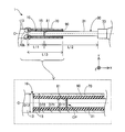
- FIG. 2 is a partial cross-sectional view around the contact portion (FIG. 1). It is a figure explaining the method of manufacturing a guide wire. It is a partial sectional view showing the whole composition of the guide wire of a 2nd embodiment.
- FIG. 5 is a partial cross-sectional view of the vicinity of a contact portion (FIG. 4) of a second embodiment. It is a figure explaining a manufacturing method of a guide wire of a 2nd embodiment. It is a partial sectional view showing the whole composition of the guide wire of a 3rd embodiment.
- FIG. 9 is a partial cross-sectional view of the vicinity of a contact portion (FIG.
- a third embodiment It is a fragmentary sectional view of the circumference of a guide wire contact part of a 4th embodiment. It is a perspective view which shows schematic structure of an inner side covering member. It is a fragmentary sectional view of the circumference of a contact part of a guide wire of a 5th embodiment. It is a fragmentary sectional view of the circumference of a contact part of a guide wire of a 6th embodiment. It is a fragmentary sectional view of the circumference of a guide wire contact part of a 7th embodiment. It is a fragmentary sectional view of the circumference of a contact part of a guide wire of an 8th embodiment.
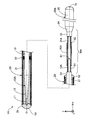
- FIG. 1 is a partial cross-sectional view illustrating the entire configuration of the guidewire 1 according to the first embodiment.
- the guidewire 1 is, for example, a medical device used when inserting a catheter into a blood vessel, and includes a first core shaft 10, a coil body 20, a second core shaft 30, a distal fixing portion 51, and a proximal end. A fixing portion 52 and a covering member 70 are provided.
- an axis passing through the center of the guidewire 1 is represented by an axis O (dashed line).
- axes passing through the centers of the first core shaft 10, the coil body 20, the second core shaft 30, and the covering member 70 all coincide with the axis O. However, the axis passing through the center of each of these members may be different from the axis O.
- FIG. 1 also shows XYZ axes that are orthogonal to each other.
- the X axis corresponds to the axial direction of the guidewire 1
- the Y axis corresponds to the height direction of the guidewire 1
- the Z axis corresponds to the width direction of the guidewire 1.
- the left side ( ⁇ X axis direction) of FIG. 1 is referred to as “the distal end side” of the guidewire 1 and each component
- the right side (+ X axis direction) of FIG. 1 is referred to as the “proximal side” of the guidewire 1 and each component member. Call.
- distal end or simply “distal end”
- base end or simply “proximal end”.
- distal side corresponds to “distal side”
- proximal side corresponds to “proximal side”.
- the first core shaft 10 is an elongated member having a large diameter at the center and a small diameter at both ends (the distal end and the proximal end).
- the first core shaft 10 is formed of a superelastic material, for example, a NiTi (nickel titanium) alloy or an alloy of NiTi and another metal.
- the first core shaft 10 has a distal small-diameter portion 11, a distal reduced-diameter portion 12, a first large-diameter portion 13, and a first small-diameter portion 15 in this order from the distal end side to the proximal end side.
- the outer diameter and length of each part can be arbitrarily determined.
- the distal small diameter portion 11 is disposed at the distal end of the first core shaft 10.
- the distal small-diameter portion 11 is a portion where the outer diameter of the first core shaft 10 is the minimum, and has a substantially cylindrical shape having a constant outer diameter.
- the distal reduced diameter portion 12 is disposed between the distal small diameter portion 11 and the first large diameter portion 13.
- the distal reduced diameter portion 12 has a substantially truncated cone shape whose outer diameter is reduced from the base end toward the distal end.
- the first large diameter portion 13 is arranged between the distal reduced diameter portion 12 and the first small diameter portion 15.
- the first large diameter portion 13 is a portion where the outer diameter of the first core shaft 10 is the largest, and has a substantially cylindrical shape having a constant outer diameter.
- the first small-diameter portion 15 is arranged at a base end of the first core shaft 10.
- the first small-diameter portion 15 has a substantially cylindrical shape having a constant outer diameter smaller than the first large-diameter portion 13 and larger than the tip small-diameter portion 11.
- the second core shaft 30 is a tapered long member having a large diameter at the base end and a small diameter at the distal end.
- the second core shaft 30 is formed of a material having higher rigidity than the first core shaft 10, for example, a stainless alloy such as SUS304 and SUS316.
- the second core shaft 30 includes a second small-diameter portion 31, a second large-diameter portion 33, a proximal reduced-diameter portion 34, and a proximal large-diameter portion 35 in order from the distal end side to the proximal end side. .
- the outer diameter and length of each part can be arbitrarily determined.
- the second small-diameter portion 31 is disposed at the tip of the second core shaft 30.
- the second small-diameter portion 31 is a portion where the outer diameter of the second core shaft 30 is the minimum, and has a substantially columnar shape having a constant outer diameter that is substantially the same as the first small-diameter portion 15 of the first core shaft 10.
- the second large-diameter portion 33 is disposed between the second small-diameter portion 31 and the proximal-end reduced-diameter portion 34.
- the second large-diameter portion 33 has a substantially cylindrical shape that is smaller than the base large-diameter portion 35 and has a constant outer diameter larger than the second small-diameter portion 31.
- the proximal reduced diameter portion 34 is disposed between the second large diameter portion 33 and the proximal large diameter portion 35.
- the proximal reduced diameter portion 34 has a substantially truncated cone shape whose outer diameter is reduced from the proximal end toward the distal end.
- the base end large diameter portion 35 is disposed at the base end of the second core shaft 30.
- the base end large diameter portion 35 is a portion where the outer diameter of the second core shaft 30 is the largest, and has a substantially cylindrical shape having a constant outer diameter.
- the distal end sides of the distal small-diameter portion 11, the distal reduced-diameter portion 12, and the first large-diameter portion 13 are covered with a coil body 20 described later.
- the base end side of the first large diameter portion 13 of the first core shaft 10, the first small diameter portion 15, and each portion of the second core shaft 30 are not covered with the coil body 20, Exposed from 20.
- the proximal large diameter portion 35 of the second core shaft 30 is used when an operator grips the guidewire 1.
- the coil body 20 has a substantially cylindrical shape formed by spirally winding the element wire 21 around the first core shaft 10.
- the wire 21 forming the coil body 20 may be a single wire composed of one wire or a stranded wire obtained by twisting a plurality of wires.
- the coil body 20 is configured as a single coil, and when the wire 21 is a stranded wire, the coil body 20 is configured as a hollow stranded wire coil.
- the coil body 20 may be configured by combining a single coil and a hollow stranded wire coil.
- the wire diameter of the element wire 21 and the average coil diameter of the coil body 20 (the average diameter of the outer and inner diameters of the coil body 20) can be arbitrarily determined.
- the wires 21 are made of, for example, stainless steel alloys such as SUS304 and SUS316, superelastic alloys such as NiTi alloys, piano wires, radiolucent alloys such as nickel-chromium alloys and cobalt alloys, gold, platinum, tungsten, and these elements. (For example, a platinum-nickel alloy) or the like. Note that the wires 21 may be formed of a known material other than the above.
- the distal end side fixing portion 51 is disposed at the distal end of the guide wire 1 and integrally holds the distal end of the distal small diameter portion 11 of the first core shaft 10 and the distal end of the coil body 20.
- the distal end side fixing portion 51 can be formed by an arbitrary bonding agent, for example, a metal solder such as silver brazing, gold brazing, zinc, Sn—Ag alloy, Au—Sn alloy, or an adhesive such as an epoxy adhesive.
- the base-side fixing portion 52 is disposed at a part of the first large-diameter portion 13 of the first core shaft 10 near the base end, and integrally forms the first core shaft 10 and the base end of the coil body 20. keeping.
- the proximal fixing portion 52 can be formed of an arbitrary bonding agent, similarly to the distal fixing portion 51. The same fixing agent may be used for the proximal fixing portion 52 and the distal fixing portion 51, or different bonding agents may be used.
- the intermediate fixing portion 61 integrally holds the coil body 20 and the first core shaft 10 in the vicinity of an intermediate portion of the coil body 20 in the direction of the axis O.
- the intermediate fixing portion 61 can be formed of an arbitrary bonding agent, similarly to the distal fixing portion 51.
- the same fixing agent may be used for the intermediate fixing portion 61 and the distal fixing portion 51, or different bonding agents may be used.
- FIG. 1 one intermediate fixing portion 61 is illustrated, but a plurality of intermediate fixing portions 61 may be provided on the guide wire 1.
- FIG. 2 is a partial sectional view of 1 pa (FIG. 1) around the contact portion.
- FIG. 2 shows a partial cross-sectional view around the contact portion of the first and second core shafts 10 and 30 in the upper part, and an enlarged view in the vicinity of the covering member 70 in the lower part.
- the XYZ axes shown in FIG. 2 correspond to the XYZ axes in FIG. 1, respectively. This point is the same for the drawings attached with XYZ axes after FIG.
- the first and second core shafts 10 and 30 are arranged facing each other (facing arrangement) with the center axis of the first core shaft 10 and the center axis of the second core shaft 30 aligned with each other. .
- the central axes of the first and second core shafts 10 and 30 coincide with the axis O.
- the center axes of the first and second core shafts 10 and 30 may coincide with each other at a position on the YZ plane different from the axis O.
- the first and second core shafts 10 and 30 may have different center axes.
- a portion where the first and second core shafts 10 and 30 face each other is referred to as a “contact portion CP”.
- the contact portion CP is a portion adjacent to the base end of the first small diameter portion 15 of the first core shaft 10 and the distal end of the second small diameter portion 31 of the second core shaft 30. .
- the first and second core shafts 10 and 30 are joined at the contact portion CP.
- the joining is performed, for example, by joining a gap between the first small-diameter portion 15 of the first core shaft 10 and the second small-diameter portion 31 of the second core shaft 30 that are arranged adjacent to each other at the contact portion CP.
- the embedding can be carried out by filling with agent 81.
- the bonding agent 81 may be disposed on the entire surface with the end surface of the bonding member, or the bonding agent 81 may be disposed only in a part of the gap and the other part may be a void.
- a metal solder such as silver brazing, gold brazing, zinc, Sn—Ag alloy, Au—Sn alloy, or an adhesive such as an epoxy-based adhesive can be used.
- the joining at the contact portion CP may be performed by welding the first and second core shafts 10 and 30.
- the first and second core shafts 10 and 30 need not be joined at the contact portion CP.
- the end surface on the base end side of the first small-diameter portion 15 may be in contact with the end surface on the distal end side of the second small-diameter portion 31.
- the end face on the proximal end side and the end face on the distal end side of the second small-diameter portion 31 may be adjacent to each other via a gap.
- the covering member 70 is a metal tubular member formed in a tubular shape (substantially cylindrical shape) having a constant outer diameter. It is preferable that the covering member 70 has a configuration in which the bending rigidity is lower than that of the second core shaft 30 and has the same elastic modulus as that of the first core shaft 10.
- the covering member 70 can be formed of a superelastic material, for example, a NiTi alloy or an alloy of NiTi and another metal, like the first core shaft 10.
- the covering member 70 may be formed of the same material as the first core shaft 10, or may be formed of a different material.
- the covering member 70 is arranged such that one end (the tip in the illustrated example) of the covering member 70 is located near the boundary 10b between the first large diameter portion 13 and the first small diameter portion 15 of the first core shaft 10. Have been.
- the covering member 70 includes a contact portion CP of the first and second core shafts 10 and 30 and a part of the first core shaft 10 adjacent to the contact portion CP (in the illustrated example, the first small-diameter portion 15). And a part of the second core shaft 30 (in the example shown, a part of the second narrow diameter portion 31 closer to the proximal end than the distal end).
- the first and second core shafts 10 and 30 joined at the contact part CP extend in the direction of the axis O so as to penetrate the lumen of the covering member 70.
- the joining layer 90 is disposed inside the covering member 70, and joins the covering member 70 to the first and second core shafts 10 and 30 (the first small-diameter portion 15 and the second small-diameter portion 31). Holding.
- the bonding layer 90 is formed over the entire gap between the covering member 70 and the first and second core shafts 10 and 30 covered by the covering member 70, and includes the first and second core shafts 10 and 30.
- the diameter part 31 is joined.
- the bonding layer 90 may be formed not on the entire gap between the covering member 70 and the first and second core shafts 10 and 30, but on only a part thereof. When formed in a part, a gap may remain between the covering member 70 and the first and second core shafts 10 and 30.
- the bonding layer 90 can be formed of an arbitrary bonding agent as in the case of the distal end side fixing portion 51. The same bonding agent may be used for the bonding layer 90 and the tip side fixing portion 51, or different bonding agents may be used.
- the length L11 of the first small diameter portion 15 of the first core shaft 10 in the direction of the axis O is the axis O of the second small diameter portion 31 of the second core shaft 30. It is shorter than the length L12 in the direction (L11 ⁇ L12).
- the length L13 of the covering member 70 in the direction of the axis O is greater than the sum of the length L11 of the first small diameter portion 15 in the direction of the axis O and the length L12 of the second small diameter portion 31 in the direction of the axis O. Short (L13 ⁇ L11 + L12).
- the length L13 of the covering member 70 in the direction of the axis O is one of the first and second small-diameter portions 15 and 31 having a shorter length in the direction of the axis O (that is, the length of the first small-diameter portion 15).
- the lengths L11, L12, L13 can be arbitrarily determined as long as the above relation is satisfied.
- the inner diameter D71 of the covering member 70 is larger than the diameter D11 of the first small diameter portion 15 of the first core shaft 10 (D71> D11).
- FIG. 3 is a view for explaining a method of manufacturing the guidewire 1.
- FIG. 3A illustrates the insertion step.
- FIG. 3B shows an arrangement step
- FIG. 3C shows an application step
- FIG. 3D shows a movement step.
- a preparation step a first core shaft 10 having a first large diameter portion 13 and a first small diameter portion 15 and a second core shaft 30 having a second large diameter portion 33 and a second small diameter portion 31 are provided.
- the tubular covering member 70 having the length L13 described above are prepared in advance.
- the covering member 70 is inserted from the second small diameter portion 31 side of the second core shaft 30 (insertion step).
- the covering member 70 is such that the base end of the covering member 70 is located near the boundary 30 b between the second small diameter portion 31 and the second large diameter portion 33 of the second core shaft 30.
- the first small diameter portion 15 of the first core shaft 10 is moved relative to the second small diameter portion 31 of the second core shaft 30 in a state where the covering member 70 is inserted.
- the first and second core shafts 10 and 30 are placed by placing the bonding agent 81 on the portion (contact portion CP) where the first small diameter portion 15 and the second small diameter portion 31 face each other. Join.
- a bonding agent for forming the bonding layer 90 is applied to the surface of the first small-diameter portion 15 and the surface of the tip of the second small-diameter portion 31 (application step).
- the bonding agent is applied to the entire surfaces of the first and second small-diameter portions 15 and 31 exposed from the covering member 70, but the bonding agent is applied to the first and second small-diameter portions 15 and 31. , 31 may be part of the surface.
- the covering member 70 is moved (slid) to the position where the bonding agent forming the bonding layer 90 is applied (moving step).
- the covering member 70 has been moved until the distal end is located near the boundary 10 b between the first large diameter portion 13 and the first small diameter portion 15 of the first core shaft 10.
- the length L13 of the covering member 70 in the direction of the axis O is equal to the length L11 of the first and second small diameter portions 15 and 31 in the direction of the axis O.
- L1 is shorter than the sum of L12 and one of the first and second small diameter portions 15 and 31 is shorter in the direction of the axis O (the length L11 of the first small diameter portion 15 in the above example). It is longer and longer than the other in the direction of the axis O (the length L12 of the second small-diameter portion 31 in the above example) (the upper part in FIG. 2). Therefore, as described with reference to FIG.
- the other of the first and second small diameter portions 15 and 31 having the longer length in the direction of the axis O in a state where the covering member 70 is inserted into the second small-diameter portion 31 (FIG. 3A), the first and second small-diameter portions 15 and 31 are arranged to face each other (FIG. 3B), and the first After applying the bonding agent to the surfaces of the first and second small diameter portions 15 and 31 (FIG. 3C), the covering member 70 is moved to a desired position on the surface of the first and second small diameter portions 15 and 31. (FIG. 3D).
- one end of the shorter one of the first and second small-diameter portions 15 and 31 becomes the larger-diameter portion (in other words, opposite to the contact portion CP).
- the covering member 70 By sliding the covering member 70 to the side end), the covering member 70 can easily cover the contact portion CP of the first and second small diameter portions 15 and 31.
- the damage of the covering member 70 can be suppressed.
- the step of forming a hole in the covering member 70 is not required, the number of manufacturing steps of the guide wire 1 can be reduced.
- one of the first and second small-diameter portions 15 and 31 is short (the first small-diameter portion 15 in the above-described example) on the distal end side of the guidewire 1.
- the material constituting the first core shaft 10 on the distal end side is a material having a lower bending rigidity than the material constituting the second core shaft 30 on the proximal end side. Therefore, the flexibility of the distal end side of the guide wire 1 can be increased.
- the first core shaft 10 located on the distal end side of the guide wire 1 is made of a superelastic alloy such as a NiTi alloy, the distal end side of the guide wire 1 is less likely to be plastically deformed. Can be prevented from being damaged on the tip side.
- the length L13 of the covering member 70 in the direction of the axis O is longer than the length L11 of the first small diameter portion 15 in the direction of the axis O (upper part in FIG. 2). For this reason, at the time of manufacturing the guide wire 1, after applying a bonding agent to the surfaces of the first and second small diameter portions 15 and 31, as shown in FIG. By moving the covering member 70 to the end portion (that is, the tip portion) opposite to the portion CP, a configuration in which the contact portion CP and the vicinity thereof are covered with the covering member 70 can be easily obtained.
- the bonding layer 90 includes the contact portion CP, the first core shaft 10 (the first small diameter portion 15), and the second core shaft inside the covering member 70. 30 (second small diameter portion 31) (FIG. 2, upper part). For this reason, operations such as a rotation operation and a pushing operation on the guide wire 1 at the hand portion (FIG. 1: base end large diameter portion 35) can be transmitted to the distal end side of the guide wire 1. Torque transmission and pushability (operability) can be improved. Further, as in the above-described embodiment, even when the rigidity of the first and second core shafts 10 and 30 is different due to the difference in the material of the first and second core shafts 10 and 30, etc.
- the rigid gap between the first and second core shafts 10 and 30 can be reduced by the covering member 70. For this reason, deformation (bending, twisting, crushing) of the first and second core shafts 10 and 30 in the vicinity of the contact portion CP can be suppressed, and the kink resistance of the guidewire 1 can be improved.
- the covering member 70 by forming the covering member 70 into a tubular shape of a superelastic material, the effect of relaxing the rigid gap by the covering member 70 can be further enhanced, and the resistance of the guidewire 1 can be improved.
- the kink property can be further improved.
- the first core shaft 10 from a superelastic material, flexibility and restorability against bending can be improved, and the second core shaft 30 is made of a material having higher rigidity than the first core shaft 10.
- the outer diameter D72 of the covering member 70 is substantially the same as the diameter D12 of the first large-diameter portion 13 of the first core shaft 10 (the lower part in FIG. 2).
- the surface shape of the connection portion between the first core shaft 10 and the covering member 70 can be made a flat shape without unevenness, and when pushing a medical device such as a balloon catheter through the guide wire 1, The medical device can be prevented from being caught, and as a result, the medical device can be prevented from being damaged.
- FIG. 4 is a partial cross-sectional view illustrating the entire configuration of the guidewire 1A according to the second embodiment.
- FIG. 5 is a partial cross-sectional view of 1pa (FIG. 4) around the contact portion according to the second embodiment.
- the configuration in the upper and lower stages in FIG. 5 is the same as that in FIG.
- the arrangement of the covering member 70A mainly in the direction of the axis O is different from that of the first embodiment.
- the covering member 70A is disposed so as to be located near the center between the first small diameter portion 15A of the first core shaft 10A and the second small diameter portion 31A of the second core shaft 30A joined at the contact portion CPA. Have been.
- the distal end of the covering member 70A is arranged at a distance from the vicinity of the boundary between the first large-diameter portion 13 and the first small-diameter portion 15A of the first core shaft 10A at a distance in the direction of the axis O.
- the base end of the covering member 70A is disposed at a distance in the direction of the axis O from near the boundary between the second large diameter portion 33 and the second small diameter portion 31A of the second core shaft 30A.
- the covering member 70A includes a contact portion CPA of the first and second core shafts 10A and 30A, and a portion of the first core shaft 10A adjacent to the contact portion CPA (in the illustrated example, A portion of the first small diameter portion 15A closer to the distal end than the base end and a portion of the second core shaft 30A (in the illustrated example, a portion closer to the proximal end than the distal end of the second small diameter portion 31A).
- Each is covering.
- the guide wire 1A includes two joining layers 91 and 92 in place of the joining layer 90 of the first embodiment.
- the joining layer 91 joins a part of the distal end side of the covering member 70A and the first core shaft 10A (the first small diameter portion 15A) inside the covering member 70A.
- the joining layer 92 joins a part of the base end of the covering member 70A and the second core shaft 30A (the second small diameter portion 31A) inside the covering member 70A.
- the bonding layers 91 and 92 are formed only at both ends of the covering member 70A in the direction of the axis O, and are not formed near the center of the covering member 70A.
- the bonding layer 91 and the bonding layer 92 can be formed with an arbitrary bonding agent as in the case of the distal end side fixing portion 51.
- the same bonding agent may be used for the bonding layer 91 and the bonding layer 92 and the front-side fixing portion 51, or different bonding agents may be used.
- the length L21 of the first small-diameter portion 15A of the first core shaft 10A in the axis O direction is the second core shaft 30A. Is smaller than the length L22 of the second small diameter portion 31A in the direction of the axis O (L21 ⁇ L22).
- the length L23 of the covering member 70A in the direction of the axis O is greater than the sum of the length L21 of the first small diameter portion 15A in the direction of the axis O and the length L22 of the second small diameter portion 31A in the direction of the axis O. Short (L23 ⁇ L21 + L22).
- the length L23 of the covering member 70A in the direction of the axis O is one of the first and second small-diameter portions 15A and 31A whose length in the direction of the axis O is shorter (the length L21 of the first small-diameter portion 15A). (L23> L21).
- the lengths L21, L22, L23 can be arbitrarily determined as long as the above relationship is satisfied.
- the relationship between the inner diameter D71 and outer diameter D72 of the covering member 70A, the diameter D11 of the first small diameter portion 15A, and the diameter D12 of the first large diameter portion 13 is also the same as in the first embodiment.
- FIG. 6 is a diagram illustrating a method of manufacturing the guidewire 1A according to the second embodiment.
- FIG. 6A illustrates the insertion step.
- FIG. 6B shows an arrangement step
- FIG. 6C shows a first coating step
- FIG. 6D shows a first moving step and a second coating step
- FIG. Each of the moving steps is illustrated.
- the preparation step, the insertion step, and the arrangement step are the same as in the first embodiment described with reference to FIG.
- a bonding agent for forming the bonding layer 91 is applied to the surface of the first small-diameter portion 15A exposed from the covering member 70A (first application step). ).
- the bonding agent is applied to the entire surface of the first small diameter portion 15A exposed from the covering member 70A.
- the application of the bonding agent may be a part of the surface of the first small diameter portion 15A.
- the covering member 70A is moved (slid) to a position where the bonding agent for forming the bonding layer 91 is applied (first moving step). .
- the covering member 70A has been moved until the distal end is located near the boundary 10b between the first large diameter portion 13 and the first small diameter portion 15A.
- a bonding agent for forming the bonding layer 92 is applied to the surface of the second small-diameter portion 31A exposed from the covering member 70A after the movement (second coating step).
- the bonding agent is applied to the entire surface of the second small diameter portion 31A exposed from the covering member 70A, but the application of the bonding agent may be a part of the surface of the second small diameter portion 31A.
- the covering member 70A is moved to the vicinity of the center between the first small diameter portion 15A and the second small diameter portion 31A (second movement step).
- the covering member 70A may be disposed at a distance in the direction of the axis O from the vicinity of the boundary between the large diameter portion and the small diameter portion of the first and second core shafts 10A and 30A. May not necessarily be located near the center of the first and second small diameter portions 15A and 31A. Further, the covering member 70A may be joined to the first and second core shafts 10A and 30A by providing a gap between the inner surface and the outer surface (surface) of the first and second core shafts 30A and 30A.
- the guide wire 1A according to the second embodiment can also provide the same effects as the first embodiment. That is, in the guide wire 1A including the first and second core shafts 10A and 30A covered by the covering member 70A, it is possible to suppress the breakage of the covering member 70A, and it is unnecessary to form a hole in the covering member 70A. Therefore, the man-hour for manufacturing the guide wire 1A can be reduced. Further, according to the guide wire 1A of the second embodiment, the two joining layers 91 and 92 are formed on the inside of the covering member 70A at both ends of the covering member 70A and the first and second small-diameter portions.
- the operation of the guide wire 1A at the hand portion can be transmitted to the distal end side, and the torque transmission and push-in (operability) of the guide wire 1A can be improved. Further, even when the first and second core shafts 10A and 30A have different rigidities, the rigidity gap can be reduced by the covering member 70A, so that the first and second core shafts in the vicinity of the contact portion CPA can be reduced. The deformation of the core shafts 10A and 30A can be suppressed, and the kink resistance of the guide wire 1A can be improved.
- FIG. 7 is a partial cross-sectional view illustrating the entire configuration of the guidewire 1B according to the third embodiment.
- FIG. 8 is a partial cross-sectional view of 1pa (FIG. 7) around the contact portion according to the third embodiment.
- the configuration of the upper and lower stages in FIG. 8 is the same as that in FIG.
- the guide wire 1B according to the third embodiment is different from the first embodiment in the configuration of the first and second core shafts 10B and 30B in the vicinity of the contact portion 1pa. 40 is provided.
- the first small-diameter portion 15 includes a first end-side small-diameter portion 15e and a first intermediate small-diameter portion 15m.
- the first end side small diameter portion 15e is provided on the base end side of the first core shaft 10B, and has a substantially cylindrical shape having a constant outer diameter smaller than the first intermediate small diameter portion 15m.
- the first intermediate small-diameter portion 15m is provided between the first end-side small-diameter portion 15e and the first large-diameter portion 13, is thicker than the first end-side small-diameter portion 15e, and has a first large-diameter portion. It has a substantially cylindrical shape with a constant outer diameter smaller than 13.
- the second small diameter portion 31 includes a second end side small diameter portion 31e and a second intermediate small diameter portion 31m.
- the second end side small diameter portion 31e is provided on the distal end side of the second core shaft 30B, and has a substantially cylindrical shape having a constant outer diameter smaller than the second intermediate small diameter portion 31m.
- the second intermediate small-diameter portion 31m is provided between the second end-side small-diameter portion 31e and the second large-diameter portion 33, is thicker than the second end-side small-diameter portion 31e, and has a second large-diameter portion. It has a substantially cylindrical shape with a constant outer diameter smaller than 33.
- the proximal end surface of the first end-side small-diameter portion 15e of the first core shaft 10B and the second end-side small diameter of the second core shaft 30B is disposed adjacent to the end face.
- the first and second core shafts 10B and 30B are joined.
- various modes can be adopted for this bonding, and the bonding may be omitted.
- the inner covering member 40 is a metal tubular member formed in a tubular shape (substantially cylindrical shape) having a constant outer diameter.
- the inner covering member 40 of the present embodiment is configured to have lower bending rigidity than the second core shaft 30B, and have the same elastic modulus as the first core shaft 10B.
- the inner covering member 40 can be formed of a superelastic material, for example, a NiTi alloy or an alloy of NiTi and another metal.
- the inner covering member 40 may be formed of the same material as the covering member 70, or may be formed of a different material.
- the inner covering member 40 includes a contact portion CPB and a part of the first core shaft 10B adjacent to the contact portion CPB (in the illustrated example, the first end side small diameter portion 15e) inside the covering member 70. , And a part of the second core shaft 30B adjacent to the contact part CPB (in the illustrated example, the second end-side small-diameter part 31e) is disposed to cover each part.
- the length of the inner covering member 40B in the direction of the axis O is the length of the first end-side small-diameter portion 15e in the direction of the axis O, and the length of the second end-side small-diameter portion 31e in the direction of the axis O. It is almost equal to the sum of Note that the length of the inner covering member 40D can be arbitrarily determined.
- the inner covering member 40 includes the first and second core shafts 10 ⁇ / b> B and 30 ⁇ / b> B (the first end side small diameter portion 15 e and the second end side small diameter portion) by the bonding layer 93 disposed inside the inner covering member 40. 31e).
- the bonding layer 93 is formed at the first end portion of the gap between the inner coating member 40 and the first and second end-side small-diameter portions 15 e and 31 e covered by the inner coating member 40. It is formed substantially entirely except for the distal end of the side small diameter portion 15e and the base end of the second end side small diameter portion 31e.
- the bonding layer 93 can be formed of an arbitrary bonding agent as in the case of the distal end side fixing portion 51.
- the same bonding agent may be used for the bonding layer 93 and the tip side fixing portion 51, or different bonding agents may be used.
- the first small-diameter portion 15 of the first core shaft 10B (that is, the first end-side small-diameter portion 15e and the first
- the length L31 of the intermediate small-diameter portion 15m) in the direction of the axis O is the length of the second small-diameter portion 31 of the second core shaft 30B (that is, the second end-side small-diameter portion 31e and the second intermediate small-diameter portion 31m). It is shorter than the length L32 in the direction of the axis O (L31 ⁇ L32).
- the relationship between the length L33 of the covering member 70 in the direction of the axis O and the lengths L31 and L32 is the same as in the first embodiment (L33 ⁇ L31 + L32, L33> L31).
- the lengths L31, 32, and 33 can be arbitrarily determined as long as the above relationship is satisfied.
- the inner covering member 40 may be further provided inside the covering member 70.
- the first small-diameter portion 15 of the first core shaft 10B and the second small-diameter portion 31 of the second core shaft 30B may be configured by two or more plural small-diameter portions.
- the guide wire 1B of the third embodiment can be manufactured by the same method as that of the first embodiment described with reference to FIG.
- the guide wire 1 ⁇ / b> B of the third embodiment can also provide the same effects as those of the first embodiment.
- the contact portion CPB and the first and second end-side small-diameter portions 15e and 31e adjacent to the contact portion CPB are provided inside the covering member 70.
- the inner covering member 40 is disposed to cover the inside. For this reason, even when the rigidity of the first and second core shafts 10B, 30B is different from each other, the rigid gap between the first and second core shafts 10B, 30B can be reduced by the inner covering member 40. .
- the inner covering member 40 can reduce the rigidity gap. For this reason, the deformation of the first and second core shafts 10B and 30B near the contact portion CPB and the deformation of the first and second core shafts 10B and 30B near the inner covering member 40 can be suppressed, and the guide wire can be suppressed.
- the kink resistance of 1B can be further improved.
- the outer diameter of the inner covering member 40 and the outer diameter of each of the first and second core shafts 10B and 30B are made to match each other, so that the first end of the first core shaft 10B is narrowed. It is possible to suppress the influence of the processing accuracy of the diameter portion 15e and the second end side small diameter portion 31e of the second core shaft 30B on the disturbance of rotation.
- the outer diameter of the inner covering member 40 and the first and second core shafts 10B and 30B have an integral structure, it is possible to suppress the ripple of the covering member 70 from being disturbed due to the inner surface processing accuracy.
- the guide wire is provided. It is possible to suppress the disturbance of the rotation of the first core shaft 10B of 1B.
- FIG. 9 is a partial cross-sectional view around the contact portion of the guide wire 1C according to the fourth embodiment.
- the configuration of the upper and lower stages in FIG. 9 is the same as that of FIG.
- the guide wire 1C of the fourth embodiment has an inner coating member 40C having a different configuration from the third embodiment in the configuration of the third embodiment.
- FIG. 10 is a perspective view showing a schematic configuration of the inner covering member 40C.
- the inner covering member 40C is a multi-strand coil formed by winding eight wires 41 in a multi-strand pattern, and has a substantially cylindrical shape having a constant outer diameter.
- the inner covering member 40C is preferably configured to have a lower bending rigidity than the second core shaft 30B.
- the inner covering member 40C is formed, for example, by tightly twisting eight wires 41 on a metal core so as to be in contact with each other, then removing the residual stress using a known heat treatment method, and extracting the metal core. Can be formed.
- the inner covering member 40C formed as described above becomes a multi-row coil having a lumen 40h (FIG. 10: broken line).
- the material of the strand 41 may be the same as the strand 21 or may be different.
- the inner covering member 40C can employ any mode.
- the number of wires constituting the inner covering member 40C is not limited to eight, and can be arbitrarily determined.
- the inner covering member 40C is not limited to the multi-layer coil, and may be a single-layer coil formed using one strand, and may be a resin material having hydrophobicity, a resin material having hydrophilicity, or a mixture thereof. May be coated.
- the inner covering member 40C various configurations may be adopted for the inner covering member 40C.
- the same effect as in the first and third embodiments can also be obtained in the guide wire 1C according to the fourth embodiment.
- the bonding agent arranged to form the bonding layer 90 is provided inside the coating member 70 with the gap between the wires of the inner coating member 40C and the inner coating member 40C. , It is possible to join the inner covering member 40C to the first and second core shafts 10B and 30B.
- the first and second core shafts 10B and 30B facilitate dispersion.
- FIG. 11 is a partial cross-sectional view around the contact portion of the guide wire 1D according to the fifth embodiment.
- the configuration of the upper and lower stages in FIG. 11 is the same as that of FIG.
- the guide wire 1D of the fifth embodiment has an inner fixing portion 95 for fixing the inner coating member 40C to the first and second core shafts 10B and 30B in the configuration of the fourth embodiment.
- the inner fixing portion 95 is disposed so as to cover the inner coating member 40C, and includes a first end-side small-diameter portion 15e of the first core shaft 10B and a second end-side small-diameter portion 31e of the second core shaft 30B.
- the inner covering member 40C are integrally fixed.
- the inner fixing portion 95 can be formed of an arbitrary bonding agent, similarly to the distal fixing portion 51. The same fixing agent may be used for the inner fixing portion 95 and the front fixing portion 51, or different bonding agents may be used.
- the inner coating member 40C and the coating member 70 may be individually fixed to the first and second core shafts 10B and 30B, respectively.
- the same effect as in the first and third embodiments can be obtained in the guide wire 1D of the fifth embodiment. Further, the same effects as in the fourth embodiment regarding stress dispersion can be obtained.
- the step of fixing the inner covering member 40C to the first and second core shafts 10B and 30B (forming the inner fixing portion 95); And fixing the covering member 70C to the first and second core shafts 10B and 30B (forming the bonding layer 90) can be performed independently.
- FIG. 12 is a partial cross-sectional view around a contact portion of a guide wire 1E according to a sixth embodiment.
- substantially the same length including the error range is also included in the “equal length”.
- the length L63 of the covering member 70 in the direction of the axis O is equal to the length L61 of the first small-diameter portion 15E in the direction of the axis O, and the length of the second small-diameter portion. It is shorter than the sum of the length L62 of the portion 31E in the direction of the axis O (L63 ⁇ L61 + L62). Furthermore, the length L63 of the covering member 70 in the direction of the axis O is longer than the length L61 of the first small diameter portion 15E in the direction of the axis O (L63> L61), and the length of the second small diameter portion 31E in the direction of the axis O. It is longer than L62 (L63> L62). Note that the lengths L61, 62, and 63 can be arbitrarily determined as long as the above relationship is satisfied.
- the lengths of the first and second small-diameter portions 15E and 31E of the first and second core shafts 10E and 30E in the direction of the axis O may be substantially the same. Also in such a sixth embodiment, the same effects as in the first embodiment can be obtained. According to the guide wire 1E of the sixth embodiment, the first and second small-diameter portions 15E and 31E have the same length in the direction of the axis O, so that the manufacture of the first and second core shafts 10E and 30E is easy. It is.
- FIG. 13 is a partial cross-sectional view around the contact portion of the guide wire 1F according to the seventh embodiment.
- the guide wire 1F of the seventh embodiment is different from the first embodiment in that the relationship between the lengths of the first and second small diameter portions 15F, 31F of the first and second core shafts 10F, 30F in the axis O direction is different from that of the first embodiment.
- the opposite is true. That is, the length L71 of the first small diameter portion 15F of the first core shaft 10F in the axis O direction is longer than the length L72 of the second small diameter portion 31F of the second core shaft 30F in the axis O direction (L71> L72). ).
- the length L73 of the covering member 70 in the direction of the axis O is shorter than the sum of the lengths L71 and L72 (L73 ⁇ L71 + L72), and is the length of the first and second small-diameter portions 15F and 31F in the direction of the axis O. Is longer (L73> L72) than the shorter one (that is, the length L72 of the second small diameter portion 31F). Note that the lengths L71, 72, 73 can be arbitrarily determined as long as the above relation is satisfied.
- the coating member 70 is configured such that one end (the base end in the illustrated example) of the coating member 70 is connected to the second small diameter portion 31F and the second large diameter portion 33 of the second core shaft 30F. Are arranged so as to be located near the boundary 30b.
- the covering member 70 includes a contact portion CPF of the first and second core shafts 10F and 30F and a part of the first and second core shafts 10F and 30F adjacent to the contact portion CPF. Is covered.
- the guide wire 1F of the seventh embodiment in the manufacturing method described with reference to FIG. 3, “the first small-diameter portion 15 of the first core shaft 10” is replaced with “the second small-diameter portion 31F of the second core shaft 30F”. , "The second small diameter portion 31 of the second core shaft 30" may be read as "the first small diameter portion 15F of the first core shaft 10F".
- the length of the first and second core shafts 10F, 30F in the direction of the axis O of the first and second small-diameter portions 15F, 31F can be arbitrarily determined, and the base end of the guide wire 1F.
- the second core shaft 30F located on the side may be shortened. Also in the seventh embodiment, the same effects as in the first embodiment can be obtained.
- FIG. 14 is a partial cross-sectional view around the contact portion of the guide wire 1G according to the eighth embodiment.
- first and second core shafts 10G and 30G include first and second intermediate portions 14 and 32, respectively.
- the first intermediate portion 14 is formed between the first large diameter portion 13 and the first small diameter portion 15 in the first core shaft 10G.
- the first intermediate portion 14 has a substantially truncated cone shape whose outer diameter increases from the base end side toward the distal end side.
- the second intermediate portion 32 is formed between the second large diameter portion 33 and the second small diameter portion 31 in the second core shaft 30G.
- the second intermediate portion 32 has a substantially truncated conical shape in which the outer diameter decreases from the base end side toward the distal end side.
- the “near the boundaries 10b and 30b” described in the first embodiment includes the first and second intermediate portions 14 and 32.
- the covering member 70 may be arranged such that the distal end of the covering member 70 is located at the base end of the first intermediate portion 14 as illustrated.
- the covering member 70 may be arranged such that the distal end of the covering member 70 is located substantially at the center of the first intermediate portion 14 in the direction of the axis O, or may be arranged at the distal end of the first intermediate portion 14.
- the configuration of the first and second core shafts 10G, 30G can be arbitrarily changed. The same effect as in the first embodiment can be obtained in the guide wire 1G of the eighth embodiment.
- FIG. 15 is a partial cross-sectional view around the contact portion of the guide wire 1H according to the ninth embodiment.
- the guide wire 1H of the ninth embodiment has a bonding layer 90H instead of the bonding layer 90 in the configuration of the first embodiment.
- the bonding layer 90H is formed in a part of a gap between the covering member 70 and the first and second core shafts 10 and 30 covered by the covering member 70.
- the bonding layer 90H is formed at substantially the center of the above-described gap in the direction of the axis O of the covering member 70, and is not formed at both ends (the distal end and the base end).
- a void in which the bonding layer 90H is not formed remains inside both ends of the covering member 70.
- the range in which the bonding layer 90H is formed can be arbitrarily changed.
- the same effect as in the first embodiment can be obtained.
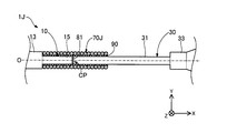
- FIG. 16 is a partial cross-sectional view around the contact portion of the guide wire 1J according to the tenth embodiment.
- the guide wire 1J of the tenth embodiment includes a covering member 70J having a configuration different from that of the covering member 70 in the configuration of the first embodiment.
- the covering member 70J is a substantially cylindrical coil body formed by spirally winding an element wire.
- the covering member 70J may be a single coil composed of one strand, or a hollow stranded coil composed of a stranded wire using a plurality of strands. Further, the covering member 70J may be the multi-row coil described with reference to FIG.
- the material of the wires constituting the covering member 70J may be the same as or different from the wires 21 of the coil body 20.
- the shape of the covering member 70J is not limited to the tubular shape and can be arbitrarily changed.
- the guide wire 1J of the tenth embodiment can also provide the same effects as those of the first and fourth embodiments.
- FIG. 17 is an enlarged view near the covering member 70 of the guide wire 1K according to the eleventh embodiment.
- the guide wire 1K of the eleventh embodiment includes an inner coating member 40K having a configuration different from that of the inner coating member 40 in the configuration of the third embodiment.
- the inner covering member 40K is a metal tubular member formed in a tubular shape (substantially cylindrical shape) having a constant outer diameter, similarly to the covering member 70.
- the inner covering member 40K may be formed of the same material as the covering member 70, or may be formed of a different material.
- the distal end side of the inner covering member 40K is fixed to the first end side small diameter portion 15e of the first core shaft 10B by caulking the distal end portion 40d.
- the base end side of the inner covering member 40K is fixed to the second end side narrow portion 31e of the second core shaft 30B by caulking the base end 40p.
- the inside of the inner covering member 40K is a space where the bonding agent is not arranged.
- the inner covering member 40K may be fixed to the first and second core shafts 10B and 30B by a method other than the bonding agent. The same effect as in the first and third embodiments can be obtained also in the guidewire 1K of the eleventh embodiment.
- the configurations of the guide wires 1 and 1A to 1K have been exemplified.
- the configuration of the guide wire can be variously changed.
- the guidewire of each of the above embodiments has been described as a medical device used when inserting a catheter into a blood vessel, but the lymph gland system, biliary system, urinary system, respiratory system, digestive system, secretory gland and It can also be configured as a guidewire inserted into each organ in the human body such as a reproductive organ.
- the guide wire has a configuration in which the entirety of the first and second core shafts (in other words, the entirety from the distal end of the first core shaft to the proximal end of the second core shaft) is covered by the coil body. You may.
- the guide wire may be commercialized in a state where the distal end side is curved in advance.
- the configuration of the first and second core shafts 10, 10A, 10B, 10E to 10G, 30, 30A, 30B, 30E to 30G has been exemplified.
- the configurations of the first core shaft and the second core shaft can be variously changed.
- the first core shaft does not have to have the distal small diameter portion or the distal reduced diameter portion
- the second core shaft does not have to have the proximal reduced diameter portion or the proximal large diameter portion.
- the first core shaft may be formed of various materials other than the superelastic material
- the second core shaft may be formed of a material that is less plastically deformed than the first core shaft.
- the first and second core shafts may be formed of the same material.
- the cross-sectional shape of each part of the first and second core shafts need not be a substantially circular shape, and various shapes (for example, a substantially rectangular shape, a substantially elliptical shape, and the like) can be adopted.
- the configuration of the coil body 20 has been described.
- the configuration of the coil body can be variously changed.
- the coil body may be configured in a tightly wound state with no gap between adjacent strands, may be formed in a loosely wound state with a gap between adjacent strands, or may be formed in a tightly wound state with a gap between adjacent strands.
- a configuration in which winding is mixed may be employed.
- the coil body may include, for example, a resin layer coated with a hydrophobic resin material, a hydrophilic resin material, or a mixture thereof.
- the cross-sectional shape of the element wire of the coil body need not be substantially circular.
- the inner covering member may be formed of a material other than metal (for example, resin).
- the inner covering member may be provided with an underlayer for facilitating adhesion of the bonding agent.
- the cross-sectional shape may be an elliptical cylindrical shape.
- the cross-sectional shape of the wire need not be substantially circular, and a shape such as a substantially elliptical shape or a substantially rectangular shape can be adopted.
- the covering member may be formed of a material other than metal (for example, resin or the like).
- the covering member may have a configuration in which the bending rigidity is substantially the same or higher than that of the second core shaft, or may have a configuration having a different elastic modulus from that of the first core shaft.
- the first and second intermediate portions described in the eighth embodiment are used.
- a configuration including a portion may be employed, and the bonding layer described in the ninth embodiment may be employed.
- Tip side fixing part 52 Base end side fixing part 61 ... Intermediate fixing part 70, 70A, 70C, 70J ... Coating member 81 ... Bonding agent 90,90 H: bonding layer 91, 92, 93: bonding layer 95: inner fixed portion
Landscapes
- Health & Medical Sciences (AREA)
- Life Sciences & Earth Sciences (AREA)
- Biophysics (AREA)
- Pulmonology (AREA)
- Engineering & Computer Science (AREA)
- Anesthesiology (AREA)
- Biomedical Technology (AREA)
- Heart & Thoracic Surgery (AREA)
- Hematology (AREA)
- Animal Behavior & Ethology (AREA)
- General Health & Medical Sciences (AREA)
- Public Health (AREA)
- Veterinary Medicine (AREA)
- Media Introduction/Drainage Providing Device (AREA)
Abstract
ガイドワイヤは、第1コアシャフトと、第2コアシャフトと、被覆部材と、接合層とを備える。第1コアシャフトは第1太径部と第1細径部とを有し、第2コアシャフトは第2太径部と第2細径部とを有する。被覆部材は、第1細径部と第2細径部とを対向配置した接置部と、接置部に隣接する第1細径部及び第2細径部の少なくとも各一部分とを覆う。接合層は、被覆部材の内側において、被覆部材と第1細径部と第2細径部とを接合する。被覆部材の軸線方向における長さは、第1細径部及び第2細径部の軸線方向におけるそれぞれの長さの和よりも短く、第1細径部及び第2細径部のうち、軸線方向における長さが短い一方よりも長い。
Description
本発明は、ガイドワイヤ及びガイドワイヤを製造する方法に関する。
血管にカテーテル等を挿入する際に用いられるガイドワイヤが知られている。このようなガイドワイヤでは、曲げに対する柔軟性や復元性、手元部分におけるガイドワイヤへの操作を先端側へと伝達するトルク伝達性や押し込み性、及び、折れ、ヨレ、潰れによる変形に強い耐キンク性が求められる。なお、トルク伝達性と押し込み性を総称して「操作性」とも呼ぶ。例えば、特許文献1~3には、ガイドワイヤにおいて、先端側に配置された第1コアシャフト(第1ワイヤ)と、第1コアシャフトの基端側に配置され、第1コアシャフトに接合された第2コアシャフト(第2ワイヤ)と、第1及び第2コアシャフトの接合部を覆う被覆部材(管状部材)とを備えることで、柔軟性や操作性を向上させることが開示されている。
しかし、特許文献1及び2に記載のガイドワイヤでは、第1及び第2コアシャフトの外周面と、被覆部材の内周面との隙間に固定材料(ろう剤、はんだ、接着剤)を充填することによって、第1及び第2コアシャフトに被覆部材を固定している。このため、余分に充填された固定材料によって被覆部材の内部の圧力が上がり、被覆部材が破損する虞があった。一方、特許文献3に記載のガイドワイヤでは、被覆部材に穴が設けられているため、被覆部材の内部の圧力が上がる可能性は低い。しかしながら、特許文献3に記載のガイドワイヤでは、ガイドワイヤを曲げた際等に被覆部材の穴の近傍で応力の集中が起こるため、依然として被覆部材が破損する虞があった。なお、このような課題は、血管系に限らず、リンパ腺系、胆道系、尿路系、気道系、消化器官系、分泌腺及び生殖器官等、人体内の各器官に挿入されるガイドワイヤに共通する。
本発明は、上述した課題を解決するためになされたものであり、被覆部材に覆われた第1及び第2コアシャフトを備えるガイドワイヤにおいて、被覆部材の破損を抑制することを目的とする。
本発明は、上述の課題の少なくとも一部を解決するためになされたものであり、以下の形態として実現することが可能である。
(1)本発明の一形態によれば、ガイドワイヤが提供される。このガイドワイヤは、第1太径部と、前記第1太径部よりも径が細い第1細径部とを有し、先端側に配置された第1コアシャフトと、第2太径部と、前記第2太径部よりも径が細い第2細径部とを有し、基端側に配置された第2コアシャフトと、前記第1細径部と前記第2細径部とを対向配置した接置部と、前記接置部に隣接する前記第1細径部及び前記第2細径部の少なくとも各一部分とを覆う被覆部材と、前記被覆部材の内側において、前記被覆部材と前記第1細径部と前記第2細径部とを接合する接合層と、を備え、前記被覆部材の軸線方向における長さは、前記第1細径部及び前記第2細径部の軸線方向におけるそれぞれの長さの和よりも短く、前記第1細径部及び前記第2細径部のうち、軸線方向における長さが短い一方よりも長い。
この構成によれば、被覆部材の軸線方向における長さは、第1及び第2細径部の軸線方向におけるそれぞれの長さの和よりも短く、第1及び第2細径部のうち軸線方向における長さが短い一方よりも長い。このため、本構成によれば、ガイドワイヤの製造に際して、第1及び第2細径部のうち軸線方向における長さが長い他方に被覆部材を挿入した状態で、第1及び第2細径部を対向配置し、第1及び第2細径部の表面に接合剤を塗布したのち、被覆部材を第1及び第2細径部の表面の所望の位置へと移動(スライド)させることができる。この結果、第1及び第2細径部の短い一方の太径部となる端部にまで被覆部材をスライドさせることで、被覆部材は第1及び第2細径部の接置部を容易に覆うことが可能となる。
さらにこの構成によれば、接合剤が塗布された状態の第1及び第2細径部の表面において、被覆部材を移動させることによって、表面に塗布された余分な接合剤は被覆部材の端部によって押し出され、排出される。従って、このようにガイドワイヤを製造すれば、被覆部材に応力集中の要因となる穴を設けることなく、被覆部材の内側に余分な接合剤(固定材料)が充填されることによる被覆部材の内部圧力の上昇を抑制できる。この結果、本構成によれば、被覆部材に覆われた第1及び第2コアシャフトを備えるガイドワイヤにおいて、被覆部材の破損を抑制することができる。また、本構成によれば、被覆部材に穴を形成する工程が不要となるため、ガイドワイヤの製造工数を低減できる。
(2)上記形態のガイドワイヤにおいて、前記軸線方向における長さが短い一方は前記第1細径部であり、且つ前記第1コアシャフトを形成する材質の曲げ剛性は前記第2コアシャフトを形成する材質の曲げ剛性よりも小さくてもよい。この構成によれば、第1及び第2細径部のうち、短い一方がガイドワイヤの先端側に配置され、更に、先端側の第1コアシャフト構成する材質は、基端側の第2コアシャフトを構成する材質と比較して、曲げ剛性が小さい材質とされる。このため、ガイドワイヤの先端側の柔軟性を高めることができる。
(3)上記形態のガイドワイヤにおいて、第1コアシャフトは超弾性材料により形成されてもよい。この構成によれば、ガイドワイヤの先端側に位置する第1コアシャフトが、例えばNiTi合金等の超弾性合金により構成されるため、ガイドワイヤの先端側が塑性変形し難くなり、その結果、ガイドワイヤの先端側の破損を抑制することが可能となる。
(4)上記形態のガイドワイヤにおいて、前記被覆部材は、前記被覆部材の一端が前記第1太径部と前記第1細径部の境界近傍に位置するように配置されており、前記接合層は、前記被覆部材の内側において、少なくとも、前記接置部と、前記第1細径部と、前記第2細径部とを接合していてもよい。この構成によれば、接合層は、被覆部材の内側において、接置部と、第1コアシャフト(第1細径部)と、第2コアシャフト(第2細径部)とを接合しているため、手元部分におけるガイドワイヤへの操作を先端側へと伝達することができ、トルク伝達性や押し込み性(操作性)を向上できる。また、第1及び第2コアシャフトの剛性がそれぞれ相違する場合であっても、被覆部材によってこの剛性ギャップを緩和することができるため、接置部近傍における第1及び第2コアシャフトの変形(折れ、ヨレ、潰れ)を抑制することができ、耐キンク性を向上できる。
(5)上記形態のガイドワイヤにおいて、前記被覆部材は、接合されている前記第1細径部と前記第2細径部との中央近傍に位置するように配置されており、前記接合層は、前記被覆部材の内側において、少なくとも、前記被覆部材の両端部分と、前記第1細径部と、前記第2細径部とをそれぞれ接合していてもよい。この構成によれば、接合層は、被覆部材の内側において、被覆部材の両端部分と、第1コアシャフト(第1細径部)と、第2コアシャフト(第2細径部)とを接合しているため、手元部分におけるガイドワイヤへの操作を先端側へと伝達することができ、トルク伝達性や押し込み性(操作性)を向上できる。また、第1及び第2コアシャフトの剛性がそれぞれ相違する場合であっても、被覆部材によってこの剛性ギャップを緩和することができるため、接置部近傍における第1及び第2コアシャフトの変形を抑制することができ、耐キンク性を向上できる。
(6)上記形態のガイドワイヤにおいて、前記第1細径部は、前記第1コアシャフトの端部側に設けられた第1端部側細径部と、前記第1端部側細径部と前記第1太径部の間に設けられ、前記第1端部側細径部よりも径が太い第1中間細径部と、を含み、前記第2細径部は、前記第2コアシャフトの端部側に設けられた第2端部側細径部と、前記第2端部側細径部と前記第2太径部の間に設けられ、前記第2端部側細径部よりも径が太い第2中間細径部と、を含み、前記被覆部材の内側には、さらに、前記接置部と、前記接置部に隣接する前記第1端部側細径部と、前記第2端部側細径部と、を覆う内側被覆部材が配置されていてもよい。この構成によれば、被覆部材の内側には、接置部と、接置部に隣接する第1及び第2端部側細径部とを覆う内側被覆部材が配置されている。このため、第1及び第2コアシャフトの剛性がそれぞれ相違する場合であっても、内側被覆部材によって、第1及び第2コアシャフトの剛性ギャップを緩和することができる。また、第1コアシャフトと、第2コアシャフトと、被覆部材との剛性がそれぞれ相違する場合であっても、内側被覆部材によって、これらの剛性ギャップを緩和することができる。このため、接置部近傍における第1及び第2コアシャフトの変形や、内側被覆部材近傍における第1及び第2コアシャフトの変形を抑制することができ、耐キンク性をさらに向上できる。
(7)上記形態のガイドワイヤにおいて、前記被覆部材の外径は、前記第1太径部の径と略同一であってもよい。この構成によれば、被覆部材の外径は、第1太径部の径と略同一であるため、第1コアシャフトと被覆部材との接続部分の表面形状を、凹凸のない平坦な形状とすることができ、ガイドワイヤを介してバルーンカテーテル等の医療機器を押し進める際に、医療機器の引っ掛かりを抑制し、その結果、医療機器の破損を抑制することができる。
(8)上記形態のガイドワイヤにおいて、前記被覆部材は、超弾性材料で形成された管形状の管状部材であってもよい。この構成によれば、被覆部材を超弾性材料の管形状とすることで、剛性ギャップの緩和効果をより強くすることができ、耐キンク性をさらに向上できる。
(9)本発明の一形態によれば、ガイドワイヤを製造する方法が提供される。この方法は、第1太径部と、前記第1太径部よりも径が細い第1細径部とを有する第1コアシャフトと、第2太径部と、前記第2太径部よりも径が細い第2細径部とを有する第2コアシャフトと、軸線方向における長さが、前記第1細径部及び前記第2細径部の軸線方向におけるそれぞれの長さの和よりも短く、かつ前記第1細径部及び前記第2細径部のうち軸線方向における長さが短い一方よりも長い被覆部材と、を準備する準備工程と、前記第2コアシャフトの前記第2細径部の側から、前記被覆部材を挿入する挿入工程と、前記第1コアシャフトの前記第1細径部と、前記第2コアシャフトの前記第2細径部とを対向配置する配置工程と、前記第1細径部と前記第2細径部とが対向配置された接置部の表面と、前記接置部に隣接すると共に前記被覆部材から露出した前記第1細径部及び前記第2細径部の各表面と、に接合剤を塗布する塗布工程と、前記被覆部材を前記接合剤が塗布された位置へと移動させる移動工程と、を備える。この方法によれば、被覆部材に覆われた第1及び第2コアシャフトを備えるガイドワイヤであって、被覆部材の破損を抑制することが可能なガイドワイヤを製造できると共に、被覆部材に穴を形成する工程が不要であるため、ガイドワイヤの製造工数を低減できる。
(10)本発明の一形態によれば、ガイドワイヤを製造する方法が提供される。この方法は、第1太径部と、前記第1太径部よりも径が細い第1細径部とを有する第1コアシャフトと、第2太径部と、前記第2太径部よりも径が細い第2細径部とを有する第2コアシャフトと、軸線方向における長さが、前記第1細径部及び前記第2細径部の軸線方向におけるそれぞれの長さの和よりも短く、かつ前記第1細径部及び前記第2細径部のうち軸線方向における長さが短い一方よりも長い被覆部材と、を準備する準備工程と、前記第2コアシャフトの前記第2細径部の側から、前記被覆部材を挿入する挿入工程と、前記第1コアシャフトの前記第1細径部と、前記第2コアシャフトの前記第2細径部とを対向配置する配置工程と、前記被覆部材から露出した前記第1細径部の表面に接合剤を塗布する第1塗布工程と、前記被覆部材を前記接合剤が塗布された位置へと移動させる第1移動工程と、前記被覆部材から露出した前記第2細径部の表面に接合剤を塗布する第2塗布工程と、前記被覆部材を、前記第1細径部と前記第2細径部との中央近傍へと移動させる第2移動工程と、を備える、方法。この方法によれば、被覆部材に覆われた第1及び第2コアシャフトを備えるガイドワイヤであって、被覆部材の破損を抑制することが可能なガイドワイヤを製造できると共に、被覆部材に穴を形成する工程が不要であるため、ガイドワイヤの製造工数を低減できる。
なお、本発明は、種々の態様で実現することが可能であり、例えば、ガイドワイヤに用いられる複数のコアシャフトからなるコアシャフト製品、コアシャフト製品の製造方法などの形態で実現することができる。
<第1実施形態>
図1は、第1実施形態のガイドワイヤ1の全体構成を示す部分断面図である。ガイドワイヤ1は、例えば血管にカテーテルを挿入する際に用いられる医療器具であり、第1コアシャフト10と、コイル体20と、第2コアシャフト30と、先端側固定部51と、基端側固定部52と、被覆部材70とを備えている。図1では、ガイドワイヤ1の中心に通る軸を軸線O(一点鎖線)で表す。以降の例では、第1コアシャフト10、コイル体20、第2コアシャフト30、及び被覆部材70の各部材の中心を通る軸は、いずれも軸線Oと一致する。しかし、これらの各部材の中心を通る軸は、それぞれ軸線Oとは相違していてもよい。
図1は、第1実施形態のガイドワイヤ1の全体構成を示す部分断面図である。ガイドワイヤ1は、例えば血管にカテーテルを挿入する際に用いられる医療器具であり、第1コアシャフト10と、コイル体20と、第2コアシャフト30と、先端側固定部51と、基端側固定部52と、被覆部材70とを備えている。図1では、ガイドワイヤ1の中心に通る軸を軸線O(一点鎖線)で表す。以降の例では、第1コアシャフト10、コイル体20、第2コアシャフト30、及び被覆部材70の各部材の中心を通る軸は、いずれも軸線Oと一致する。しかし、これらの各部材の中心を通る軸は、それぞれ軸線Oとは相違していてもよい。
また、図1には、相互に直交するXYZ軸が図示されている。X軸は、ガイドワイヤ1の軸線方向に対応し、Y軸は、ガイドワイヤ1の高さ方向に対応し、Z軸は、ガイドワイヤ1の幅方向に対応する。図1の左側(-X軸方向)をガイドワイヤ1及び各構成部材の「先端側」と呼び、図1の右側(+X軸方向)をガイドワイヤ1及び各構成部材の「基端側」と呼ぶ。また、ガイドワイヤ1及び各構成部材について、先端側に位置する端部を「先端部」または単に「先端」と呼び、基端側に位置する端部を「基端部」または単に「基端」と呼ぶ。本実施形態において、先端側は「遠位側」に相当し、基端側は「近位側」に相当する。これらの点は、図1以降の全体構成を示す図においても共通する。
第1コアシャフト10は、中央が太径で、両端側(先端側、基端側)が細径とされた長尺状の部材である。第1コアシャフト10は、超弾性材料、例えば、NiTi(ニッケルチタン)合金や、NiTiと他の金属との合金により形成されている。第1コアシャフト10は、先端側から基端側に向かって順に、先端細径部11、先端縮径部12、第1太径部13、第1細径部15を有している。各部の外径や長さは任意に決定できる。
先端細径部11は、第1コアシャフト10の先端部に配置されている。先端細径部11は、第1コアシャフト10の外径が最小の部分であり、一定の外径を有する略円柱形状である。先端縮径部12は、先端細径部11と第1太径部13との間に配置されている。先端縮径部12は、基端側から先端側に向かって外径が縮径した略円錐台形状である。第1太径部13は、先端縮径部12と第1細径部15との間に配置されている。第1太径部13は、第1コアシャフト10の外径が最大の部分であり、一定の外径を有する略円柱形状である。第1細径部15は、第1コアシャフト10の基端部に配置されている。第1細径部15は、第1太径部13よりも小さく、かつ、先端細径部11よりも大きな一定の外径を有する略円柱形状である。
第2コアシャフト30は、基端側が太径で先端側が細径とされた、先細りした長尺状の部材である。第2コアシャフト30は、第1コアシャフト10よりも高い剛性を有する材料、例えば、SUS304、SUS316等のステンレス合金により形成されている。第2コアシャフト30は、先端側から基端側に向かって順に、第2細径部31、第2太径部33、基端縮径部34、基端太径部35を有している。各部の外径や長さは任意に決定できる。
第2細径部31は、第2コアシャフト30の先端部に配置されている。第2細径部31は、第2コアシャフト30の外径が最小の部分であり、第1コアシャフト10の第1細径部15と略同一な一定の外径を有する略円柱形状である。第2太径部33は、第2細径部31と基端縮径部34との間に配置されている。第2太径部33は、基端太径部35よりも小さく、かつ、第2細径部31よりも大きな一定の外径を有する略円柱形状である。基端縮径部34は、第2太径部33と基端太径部35との間に配置されている。基端縮径部34は、基端側から先端側に向かって外径が縮径した略円錐台形状である。基端太径部35は、第2コアシャフト30の基端部に配置されている。基端太径部35は、第2コアシャフト30の外径が最大の部分であり、一定の外径を有する略円柱形状である。
第1コアシャフト10のうち、先端細径部11、先端縮径部12、及び第1太径部13の先端側は、後述するコイル体20によって覆われている。一方、第1コアシャフト10の第1太径部13の基端側と、第1細径部15と、第2コアシャフト30の各部とは、コイル体20によって覆われておらず、コイル体20から露出している。第2コアシャフト30の基端太径部35は、術者がガイドワイヤ1を把持する際に使用される。
コイル体20は、第1コアシャフト10に対して素線21を螺旋状に巻回して形成される略円筒形状である。コイル体20を形成する素線21は、1本の素線からなる単線でもよいし、複数の素線を撚り合せた撚線でもよい。素線21を単線とした場合、コイル体20は単コイルとして構成され、素線21を撚線とした場合、コイル体20は中空撚線コイルとして構成される。また、単コイルと中空撚線コイルとを組み合わせてコイル体20を構成してもよい。素線21の線径と、コイル体20におけるコイル平均径(コイル体20の外径と内径の平均径)とは、任意に決定できる。
素線21は、例えば、SUS304、SUS316等のステンレス合金、NiTi合金等の超弾性合金、ピアノ線、ニッケル-クロム系合金、コバルト合金等の放射線透過性合金、金、白金、タングステン、これらの元素を含む合金(例えば、白金-ニッケル合金)等の放射線不透過性合金で形成することができる。なお、素線21は、上記以外の公知の材料によって形成されてもよい。
先端側固定部51は、ガイドワイヤ1の先端部に配置され、第1コアシャフト10の先端細径部11の先端部と、コイル体20の先端部とを一体的に保持している。先端側固定部51は、任意の接合剤、例えば、銀ロウ、金ロウ、亜鉛、Sn-Ag合金、Au-Sn合金等の金属はんだや、エポキシ系接着剤などの接着剤によって形成できる。基端側固定部52は、第1コアシャフト10の第1太径部13の基端側寄りの一部分に配置され、第1コアシャフト10と、コイル体20の基端部とを一体的に保持している。基端側固定部52は、先端側固定部51と同様に任意の接合剤によって形成できる。基端側固定部52と先端側固定部51とは、同じ接合剤を用いてもよく、異なる接合剤を用いてもよい。
中間固定部61は、コイル体20の軸線O方向の中間部近傍において、コイル体20と、第1コアシャフト10とを一体的に保持している。中間固定部61は、先端側固定部51と同様に任意の接合剤によって形成できる。中間固定部61と先端側固定部51とは、同じ接合剤を用いてもよく、異なる接合剤を用いてもよい。図1では、1つの中間固定部61について例示したが、ガイドワイヤ1には複数の中間固定部61を設けてもよい。
図2は、接置部周辺1pa(図1)の部分断面図である。図2では、上段に第1及び第2コアシャフト10,30の接置部周辺の部分断面図を図示し、下段に被覆部材70近傍の拡大図を図示する。図2に示すXYZ軸は、図1のXYZ軸にそれぞれ対応する。この点は、図2以降のXYZ軸を付した図についても同様である。
第1及び第2コアシャフト10,30は、第1コアシャフト10の中心軸と、第2コアシャフト30の中心軸とを互いに一致させた状態で、対向して配置(対向配置)されている。図示の例では、第1及び第2コアシャフト10,30の各中心軸は、軸線Oに一致している。しかし、第1及び第2コアシャフト10,30は、軸線Oとは異なるYZ平面上の位置で互いの中心軸が一致していてもよい。また、第1及び第2コアシャフト10,30は、互いの中心軸が相違していてもよい。以降、第1及び第2コアシャフト10,30が対向する部分を「接置部CP」と呼ぶ。図示の例では、接置部CPは、第1コアシャフト10の第1細径部15の基端部と、第2コアシャフト30の第2細径部31の先端部との隣接部分である。
本実施形態では、第1及び第2コアシャフト10,30は、接置部CPにおいて接合されている。接合は、例えば、接置部CPにおいて隣接して配置された第1コアシャフト10の第1細径部15と、第2コアシャフト30の第2細径部31との間の隙間を、接合剤81で埋め固めることにより実施できる。この際、第1細径部15と第2細径部31との間の隙間の全体(換言すれば、第1細径部15の基端側の端面と第2細径部31の先端側の端面との全面)に接合剤81が配置されてもよいし、隙間の一部分にのみ接合剤81が配置されて他の部分は空隙であってもよい。接合剤81には、例えば、銀ロウ、金ロウ、亜鉛、Sn-Ag合金、Au-Sn合金等の金属はんだや、エポキシ系接着剤などの接着剤を使用できる。また、接置部CPにおける接合は、第1及び第2コアシャフト10,30の溶接により実施されてもよい。
なお、第1及び第2コアシャフト10,30は、接置部CPにおいて接合されていなくてもよい。この場合、接置部CPでは、第1細径部15の基端側の端面と、第2細径部31の先端側の端面とが接触していてもよく、第1細径部15の基端側の端面と、第2細径部31の先端側の端面とが空隙を介して隣接していてもよい。
被覆部材70は、一定の外径を有する管形状(略円筒形状)に形成された金属製の管状部材である。被覆部材70は、第2コアシャフト30よりも曲げ剛性が低く、かつ、第1コアシャフト10と同程度の弾性率を有する構成とされることが好ましい。被覆部材70は、第1コアシャフト10と同様に、超弾性材料、例えば、NiTi合金や、NiTiと他の金属との合金により形成できる。被覆部材70は、第1コアシャフト10と同じ材料により形成されてもよく、異なる材料により形成されてもよい。
被覆部材70は、被覆部材70の一端(図示の例では、先端部)が、第1コアシャフト10の第1太径部13と第1細径部15の境界近傍10bに位置するように配置されている。また、被覆部材70は、第1及び第2コアシャフト10,30の接置部CPと、接置部CPに隣接する第1コアシャフト10の一部分(図示の例では、第1細径部15の基端部より先端側)と、第2コアシャフト30の一部分(図示の例では、第2細径部31の先端部より基端側の一部分)と、をそれぞれ覆っている。換言すれば、接置部CPにおいて接合された第1及び第2コアシャフト10,30は、被覆部材70の内腔を貫通するように、軸線O方向に延伸している。
接合層90は、被覆部材70の内側に配置され、被覆部材70と、第1及び第2コアシャフト10,30(第1細径部15、第2細径部31)とを接合し、一体的に保持している。図示の例では、接合層90は、被覆部材70と、被覆部材70に覆われた第1及び第2コアシャフト10,30との間の隙間の全体に形成されており、第1及び第2細径部15,31の接置部CPと、接置部CPに隣接する第1コアシャフト10の第1細径部15と、接置部CPに隣接する第2コアシャフト30の第2細径部31とを接合している。なお、接合層90は、被覆部材70と、第1及び第2コアシャフト10,30との間の隙間の全体ではなく、一部分にのみ形成されてもよい。一部分に形成される場合、被覆部材70と、第1及び第2コアシャフト10,30との間には、空隙が残存していてもよい。接合層90は、接合層90は、先端側固定部51と同様に任意の接合剤によって形成できる。接合層90と先端側固定部51とは、同じ接合剤を用いてもよく、異なる接合剤を用いてもよい。
図2上段に示すように、本実施形態では、第1コアシャフト10の第1細径部15の軸線O方向における長さL11は、第2コアシャフト30の第2細径部31の軸線O方向における長さL12よりも短い(L11<L12)。また、被覆部材70の軸線O方向における長さL13は、第1細径部15の軸線O方向における長さL11と、第2細径部31の軸線O方向における長さL12との和よりも短い(L13<L11+L12)。さらに、被覆部材70の軸線O方向における長さL13は、第1及び第2細径部15,31のうち、軸線O方向における長さが短い一方(すなわち、第1細径部15の長さL11)よりも長い(L13>L11)。なお、長さL11,12,13は、上述の関係を満たす限りにおいて任意に決定できる。
図2下段に示すように、本実施形態では、被覆部材70の内径D71は、第1コアシャフト10の第1細径部15の径D11よりも大きい(D71>D11)。また、被覆部材70の外径D72は、第1コアシャフト10の第1太径部13の径D12と略同一である(D72=D12)。なお、内径D71,外径D72,径D11,12は、上述の関係を満たす限りにおいて任意に決定できる。
図3は、ガイドワイヤ1を製造する方法について説明する図である。図3(A)は挿入工程を図示している。同様に、図3(B)は配置工程を、図3(C)は塗布工程を、図3(D)は移動工程をそれぞれ図示している。まず、準備工程において、第1太径部13と第1細径部15とを有する第1コアシャフト10と、第2太径部33と第2細径部31とを有する第2コアシャフト30と、上述した長さL13を有する管形状の被覆部材70と、をそれぞれ予め準備しておく。
次に、図3(A)の白抜き矢印に示すように、第2コアシャフト30の第2細径部31の側から、被覆部材70を挿入する(挿入工程)。図3(B)の例では、被覆部材70は、被覆部材70の基端部が、第2コアシャフト30の第2細径部31と第2太径部33との境界近傍30bに位置するまで移動(スライド)されている。次に、図3(B)に示すように、被覆部材70が挿入された状態の第2コアシャフト30の第2細径部31に対して、第1コアシャフト10の第1細径部15を対向した状態で配置する(配置工程)。そして、第1細径部15と第2細径部31とが対向する部分(接置部CP)に対して、接合剤81を配置することで、第1及び第2コアシャフト10,30を接合する。
次に、図3(C)に示すように、接置部CPの表面と、接置部CPに隣接すると共に被覆部材70から露出した第1及び第2細径部15,31の各表面(図示の例では、第1細径部15の表面と、第2細径部31の先端側の表面)と、に対して接合層90を形成するための接合剤を塗布する(塗布工程)。図示の例では、被覆部材70から露出した第1及び第2細径部15,31の表面全体に接合剤を塗布しているが、接合剤の塗布は、第1及び第2細径部15,31の表面の一部分でもよい。次に、図3(D)の白抜き矢印に示すように、被覆部材70を、接合層90を形成する接合剤が塗布された位置へと移動(スライド)させる(移動工程)。図示の例では、被覆部材70は、先端部が第1コアシャフト10の第1太径部13と第1細径部15との境界近傍10bに位置するまで移動されている。
以上のように、本実施形態のガイドワイヤ1によれば、被覆部材70の軸線O方向における長さL13は、第1及び第2細径部15,31の軸線O方向における各長さL11,L12の和よりも短く、かつ、第1及び第2細径部15,31のうち軸線O方向における長さが短い一方(上述の例では、第1細径部15の長さL11)よりも長く、かつ軸線O方向における長さが長い他方(上述の例では、第2細径部31の長さL12)よりも短い(図2上段)。このため、図3で説明したように、本実施形態のガイドワイヤ1の製造に際しては、第1及び第2細径部15,31のうち軸線O方向における長さが長い他方(上述の例では、第2細径部31)に被覆部材70を挿入した状態(図3(A))で、第1及び第2細径部15,31を対向配置(図3(B))し、第1及び第2細径部15,31の表面に接合剤を塗布(図3(C))したのち、被覆部材70を第1及び第2細径部15,31の表面の所望の位置へと移動(図3(D))させることができる。この結果、第1及び第2細径部15,31の短い一方(上述の例では、第1細径部15)の太径部となる端部(換言すれば、接置部CPとは逆側の端部)にまで被覆部材70をスライドさせることで、被覆部材70は第1及び第2細径部15,31の接置部CPを容易に覆うことが可能となる。
図3(D)のように、接合剤が塗布された状態の第1及び第2細径部15,31の表面において、被覆部材70を移動させることによって、第1及び第2細径部15,31の表面に塗布された余分な接合剤は、被覆部材70の端部(端面)によって押し出されて排出される。従って、図3のようにしてガイドワイヤ1を製造すれば、被覆部材70に応力集中の要因となる穴を設けることなく、被覆部材70の内側に余分な接合剤(固定材料)が充填されることによる被覆部材70の内部圧力の上昇を抑制できる。この結果、本実施形態によれば、被覆部材70に覆われた第1及び第2コアシャフト10,30を備えるガイドワイヤ1において、被覆部材70の破損を抑制することができる。また、本実施形態によれば、被覆部材70に穴を形成する工程が不要となるため、ガイドワイヤ1の製造工数を低減できる。
また、本実施形態のガイドワイヤ1によれば、第1及び第2細径部15,31のうち、短い一方(上述の例では、第1細径部15)がガイドワイヤ1の先端側に配置され、更に、先端側の第1コアシャフト10構成する材質は、基端側の第2コアシャフト30を構成する材質と比較して、曲げ剛性が小さい材質とされる。このため、ガイドワイヤ1の先端側の柔軟性を高めることができる。また、ガイドワイヤ1の先端側に位置する第1コアシャフト10が、例えばNiTi合金等の超弾性合金により構成されるため、ガイドワイヤ1の先端側が塑性変形し難くなり、その結果、ガイドワイヤ1の先端側の破損を抑制することが可能となる。
さらに、本実施形態のガイドワイヤ1によれば、被覆部材70の軸線O方向における長さL13は、第1細径部15の軸線O方向における長さL11よりも長い(図2上段)。このため、ガイドワイヤ1の製造に際して、第1及び第2細径部15,31の表面に接合剤を塗布したのち、図3(D)に示すように、第1細径部15の接置部CPとは逆側の端部(すなわち先端部)まで被覆部材70を移動させることによって、簡単に、接置部CP及びその近傍が被覆部材70によって覆われた構成を得ることができる。
さらに、本実施形態のガイドワイヤ1によれば、接合層90は、被覆部材70の内側において、接置部CPと、第1コアシャフト10(第1細径部15)と、第2コアシャフト30(第2細径部31)とを接合している(図2上段)。このため、手元部分(図1:基端太径部35)におけるガイドワイヤ1への回転操作や押し込み操作等の操作を、ガイドワイヤ1の先端側へと伝達することができ、ガイドワイヤ1のトルク伝達性や押し込み性(操作性)を向上できる。また、上記実施形態のように、第1及び第2コアシャフト10,30の材料の相違等に起因して、第1及び第2コアシャフト10,30の剛性がそれぞれ相違する場合であっても、被覆部材70によって、第1及び第2コアシャフト10,30の剛性ギャップを緩和することができる。このため、接置部CP近傍における第1及び第2コアシャフト10,30の変形(折れ、ヨレ、潰れ)を抑制することができ、ガイドワイヤ1の耐キンク性を向上できる。
さらに、本実施形態のガイドワイヤ1によれば、被覆部材70を超弾性材料の管形状とすることで、被覆部材70による剛性ギャップの緩和効果をより強くすることができ、ガイドワイヤ1の耐キンク性をさらに向上できる。また、第1コアシャフト10を超弾性材料で形成することで、曲げに対する柔軟性や復元性を向上させることができ、第2コアシャフト30を第1コアシャフト10よりも高い剛性を有する材料で形成することで、ガイドワイヤ1のトルク伝達性や押し込み性(操作性)を向上させることができる。
さらに、本実施形態のガイドワイヤ1によれば、被覆部材70の外径D72は、第1コアシャフト10の第1太径部13の径D12と略同一である(図2下段)。このため、第1コアシャフト10と被覆部材70との接続部分の表面形状を、凹凸のない平坦な形状とすることができ、ガイドワイヤ1を介してバルーンカテーテル等の医療機器を押し進める際に、医療機器の引っ掛かりを抑制し、その結果、医療機器の破損を抑制することができる。
<第2実施形態>
図4は、第2実施形態のガイドワイヤ1Aの全体構成を示す部分断面図である。図5は、第2実施形態の接置部周辺1pa(図4)の部分断面図である。図5における上段下段の構成は、図2と同様である。第2実施形態のガイドワイヤ1Aでは、主として、軸線O方向における被覆部材70Aの配置が第1実施形態とは相違する。
図4は、第2実施形態のガイドワイヤ1Aの全体構成を示す部分断面図である。図5は、第2実施形態の接置部周辺1pa(図4)の部分断面図である。図5における上段下段の構成は、図2と同様である。第2実施形態のガイドワイヤ1Aでは、主として、軸線O方向における被覆部材70Aの配置が第1実施形態とは相違する。
被覆部材70Aは、接置部CPAにおいて接合されている第1コアシャフト10Aの第1細径部15Aと、第2コアシャフト30Aの第2細径部31Aとの中央近傍に位置するように配置されている。換言すれば、被覆部材70Aの先端部は、第1コアシャフト10Aの第1太径部13と第1細径部15Aとの境界近傍から、軸線O方向に距離を空けて配置されている。また、被覆部材70Aの基端部は、第2コアシャフト30Aの第2太径部33と第2細径部31Aとの境界近傍から、軸線O方向に距離を空けて配置されている。被覆部材70Aは、第1実施形態と同様に、第1及び第2コアシャフト10A,30Aの接置部CPAと、接置部CPAに隣接する第1コアシャフト10Aの一部分(図示の例では、第1細径部15Aの基端部より先端側の一部分)と、第2コアシャフト30Aの一部分(図示の例では、第2細径部31Aの先端部より基端側の一部分)と、をそれぞれ覆っている。
また、ガイドワイヤ1Aは、第1実施形態の接合層90に代えて、2か所の接合層91及び接合層92を備えている。接合層91は、被覆部材70Aの内側において、被覆部材70Aの先端側の一部分と、第1コアシャフト10A(第1細径部15A)とを接合している。接合層92は、被覆部材70Aの内側において、被覆部材70Aの基端側の一部分と、第2コアシャフト30A(第2細径部31A)とを接合している。図示の例では、接合層91及び接合層92は、軸線O方向における被覆部材70Aの両端部分にのみ形成されており、被覆部材70Aの中央部近傍には形成されていない。すなわち、被覆部材70Aの中央部近傍には、被覆部材70Aの内側面と、接置部CPAに隣接する第1及び第2細径部15A,31Aの外側面との間に空隙が存在している。接合層91及び接合層92は、先端側固定部51と同様に任意の接合剤によって形成できる。接合層91及び接合層92と先端側固定部51とは、同じ接合剤を用いてもよく、異なる接合剤を用いてもよい。
図5上段に示すように、第2実施形態においても、第1実施形態と同様に、第1コアシャフト10Aの第1細径部15Aの軸線O方向における長さL21は、第2コアシャフト30Aの第2細径部31Aの軸線O方向における長さL22よりも短い(L21<L22)。また、被覆部材70Aの軸線O方向における長さL23は、第1細径部15Aの軸線O方向における長さL21と、第2細径部31Aの軸線O方向における長さL22との和よりも短い(L23<L21+L22)。さらに、被覆部材70Aの軸線O方向における長さL23は、第1及び第2細径部15A,31Aのうち、軸線O方向における長さが短い一方(第1細径部15Aの長さL21)よりも長い(L23>L21)。長さL21,22,23は、上述の関係を満たす限りにおいて任意に決定できる。また、被覆部材70Aの内径D71及び外径D72、第1細径部15Aの径D11、第1太径部13の径D12の大小関係についても、第1実施形態と同様である。
図6は、第2実施形態のガイドワイヤ1Aを製造する方法について説明する図である。図6(A)は挿入工程を図示している。同様に、図6(B)は配置工程を、図6(C)は第1塗布工程を、図6(D)は第1移動工程及び第2塗布工程を、図6(E)は第2移動工程をそれぞれ図示している。準備工程、挿入工程、配置工程については、図3で説明した第1実施形態と同様である。
配置工程の終了後、図6(C)に示すように、被覆部材70Aから露出した第1細径部15Aの表面に、接合層91を形成するための接合剤を塗布する(第1塗布工程)。図示の例では、被覆部材70Aから露出した第1細径部15Aの表面全体に接合剤を塗布しているが、接合剤の塗布は第1細径部15Aの表面の一部分でもよい。次に、図6(D)の白抜き矢印に示すように、被覆部材70Aを、接合層91を形成するための接合剤が塗布された位置へと移動(スライド)させる(第1移動工程)。図示の例では、被覆部材70Aは、先端部が第1太径部13と第1細径部15Aとの境界近傍10bに位置するまで移動されている。
そして、図6(D)に示すように、移動後の被覆部材70Aから露出した第2細径部31Aの表面に、接合層92を形成するための接合剤を塗布する(第2塗布工程)。図示の例では、被覆部材70Aから露出した第2細径部31Aの表面全体に接合剤を塗布しているが、接合剤の塗布は第2細径部31Aの表面の一部分でもよい。最後に、図6(E)の白抜き矢印に示すように、被覆部材70Aを、第1細径部15Aと第2細径部31Aとの中央近傍まで移動させる(第2移動工程)。
このように、被覆部材70Aは、第1及び第2コアシャフト10A,30Aの太径部及び細径部の境界近傍から、軸線O方向において距離を空けて配置されていてもよく、被覆部材70Aの配置は、必ずしも、第1及び第2細径部15A,31Aの中央近傍でなくてもよい。また、被覆部材70Aは、内側面において、第1及び第2コアシャフト10A,30Aの外側面(表面)との間に空隙を設けて接合されていてもよい。
このような第2実施形態のガイドワイヤ1Aにおいても、第1実施形態と同様の効果を奏することができる。すなわち、被覆部材70Aに覆われた第1及び第2コアシャフト10A,30Aを備えるガイドワイヤ1Aにおいて、被覆部材70Aの破損を抑制することができると共に、被覆部材70Aに穴を形成する工程が不要となるため、ガイドワイヤ1Aの製造工数を低減できる。また、第2実施形態のガイドワイヤ1Aによれば、2か所の接合層91及び接合層92が、被覆部材70Aの内側において、被覆部材70Aの両端部分と、第1及び第2細径部15A,31Aとを接合しているため、手元部分におけるガイドワイヤ1Aへの操作を先端側へと伝達することができ、ガイドワイヤ1Aのトルク伝達性や押し込み性(操作性)を向上できる。また、第1及び第2コアシャフト10A,30Aの剛性がそれぞれ相違する場合であっても、被覆部材70Aによってこの剛性ギャップを緩和することができるため、接置部CPA近傍における第1及び第2コアシャフト10A,30Aの変形を抑制することができ、ガイドワイヤ1Aの耐キンク性を向上できる。
<第3実施形態>
図7は、第3実施形態のガイドワイヤ1Bの全体構成を示す部分断面図である。図8は、第3実施形態の接置部周辺1pa(図7)の部分断面図である。図8における上段下段の構成は、図2と同様である。第3実施形態のガイドワイヤ1Bは、接置部周辺1paにおける第1及び第2コアシャフト10B,30Bの構成が第1実施形態とは相違すると共に、被覆部材70の内側において、さらに内側被覆部材40を備えている。
図7は、第3実施形態のガイドワイヤ1Bの全体構成を示す部分断面図である。図8は、第3実施形態の接置部周辺1pa(図7)の部分断面図である。図8における上段下段の構成は、図2と同様である。第3実施形態のガイドワイヤ1Bは、接置部周辺1paにおける第1及び第2コアシャフト10B,30Bの構成が第1実施形態とは相違すると共に、被覆部材70の内側において、さらに内側被覆部材40を備えている。
第1コアシャフト10Bは、第1細径部15が、第1端部側細径部15e及び第1中間細径部15mを備えている。第1端部側細径部15eは、第1コアシャフト10Bの基端部側に設けられ、第1中間細径部15mよりも細い一定の外径を有する略円柱形状である。第1中間細径部15mは、第1端部側細径部15eと第1太径部13との間に設けられ、第1端部側細径部15eよりも太く、第1太径部13よりも細い一定の外径を有する略円柱形状である。第2コアシャフト30Bは、第2細径部31が、第2端部側細径部31e及び第2中間細径部31mを備えている。第2端部側細径部31eは、第2コアシャフト30Bの先端部側に設けられ、第2中間細径部31mよりも細い一定の外径を有する略円柱形状である。第2中間細径部31mは、第2端部側細径部31eと第2太径部33との間に設けられ、第2端部側細径部31eよりも太く、第2太径部33よりも細い一定の外径を有する略円柱形状である。
図8下段に示すように、接置部CPBでは、第1コアシャフト10Bの第1端部側細径部15eの基端側の端面と、第2コアシャフト30Bの第2端部側細径部31eの先端側の端面と、が隣接して配置されている。接置部CPBでは、第1及び第2コアシャフト10B,30Bが接合されている。この接合には、第1実施形態と同様に、種々の態様を採用することができるほか、接合を省略してもよい。
内側被覆部材40は、一定の外径を有する管形状(略円筒形状)に形成された金属製の管状部材である。本実施形態の内側被覆部材40は、第2コアシャフト30Bよりも曲げ剛性が低く、かつ、第1コアシャフト10Bと同程度の弾性率を有する構成である。内側被覆部材40は、被覆部材70と同様に、超弾性材料、例えば、NiTi合金や、NiTiと他の金属との合金により形成できる。内側被覆部材40は、被覆部材70と同じ材料により形成されてもよく、異なる材料により形成されてもよい。
内側被覆部材40は、被覆部材70の内側において、接置部CPBと、接置部CPBに隣接する第1コアシャフト10Bの一部分(図示の例では、第1端部側細径部15e)と、接置部CPBに隣接する第2コアシャフト30Bの一部分(図示の例では、第2端部側細径部31e)と、をそれぞれ覆うように配置されている。本実施形態では、内側被覆部材40Bの軸線O方向における長さは、第1端部側細径部15eの軸線O方向における長さと、第2端部側細径部31eの軸線O方向における長さの和とほぼ等しい。なお、内側被覆部材40Dの長さは任意に決定できる。
内側被覆部材40は、内側被覆部材40の内側に配置された接合層93によって、第1及び第2コアシャフト10B,30B(第1端部側細径部15e、第2端部側細径部31e)と接合されている。図示の例では、接合層93は、内側被覆部材40と、内側被覆部材40に覆われた第1及び第2端部側細径部15e,31eとの間の隙間のうち、第1端部側細径部15eの先端部と第2端部側細径部31eの基端部とを除く略全体に形成されている。このような接合層93によって、第1及び第2端部側細径部15e,31eの接置部CPBと、接置部CPBに隣接する第1及び第2端部側細径部15e,31eとが接合されている。接合層93は、先端側固定部51と同様に任意の接合剤によって形成できる。接合層93と先端側固定部51とは、同じ接合剤を用いてもよく、異なる接合剤を用いてもよい。
図8上段に示すように、第3実施形態においても、第1実施形態と同様に、第1コアシャフト10Bの第1細径部15(すなわち、第1端部側細径部15e及び第1中間細径部15m)の軸線O方向における長さL31は、第2コアシャフト30Bの第2細径部31(すなわち、第2端部側細径部31e及び第2中間細径部31m)の軸線O方向における長さL32よりも短い(L31<L32)。また、被覆部材70の軸線O方向における長さL33と、長さL31,32の関係についても第1実施形態と同様である(L33<L31+L32、L33>L31)。長さL31,32,33は、上述の関係を満たす限りにおいて任意に決定できる。
このように、被覆部材70の内側にはさらに、内側被覆部材40を備えていてもよい。また、第1コアシャフト10Bの第1細径部15や、第2コアシャフト30Bの第2細径部31は、2つ以上の複数の細径部から構成されていてもよい。第3実施形態のガイドワイヤ1Bは、図3で説明した第1実施形態と同様の方法で製造することができる。
このような第3実施形態のガイドワイヤ1Bにおいても、第1実施形態と同様の効果を奏することができる。さらに、第3実施形態のガイドワイヤ1Bによれば、被覆部材70の内側には、接置部CPBと、接置部CPBに隣接する第1及び第2端部側細径部15e,31eとを覆う内側被覆部材40が配置されている。このため、第1及び第2コアシャフト10B,30Bの剛性がそれぞれ相違する場合であっても、内側被覆部材40によって、第1及び第2コアシャフト10B,30Bの剛性ギャップを緩和することができる。また、第1コアシャフト10Bと、第2コアシャフト30Bと、被覆部材70との剛性がそれぞれ相違する場合であっても、内側被覆部材40によって、これらの剛性ギャップを緩和することができる。このため、接置部CPB近傍における第1及び第2コアシャフト10B,30Bの変形や、内側被覆部材40近傍における第1及び第2コアシャフト10B,30Bの変形を抑制することができ、ガイドワイヤ1Bの耐キンク性をさらに向上できる。
さらに、長尺であるガイドワイヤ1Bを基端側で軸線Oを中心として回転させた場合に、接合後の被覆部材70、第1及び第2コアシャフト10B、30Bの夫々の中心軸が加工誤差のために軸線Oからずれを生じていると、ガイドワイヤ1Bの第2コアシャフト30Bを把持し、軸線Oを回転軸として回転させた場合、第1コアシャフト10Bの回転に乱れが生じることになる。このような回転の乱れは極力小さくなるように組み付けを行うことが望ましいが、組み付けに時間を要することになる。
第3実施形態のガイドワイヤでは、内部被覆部材40の外径と第1及び第2コアシャフト10B、30B夫々の外径とを一致させることで、第1コアシャフト10Bの第1端部側細径部15eと第2コアシャフト30Bの第2端部側細径部31eの加工精度による回転の乱れへの波及を抑制することができる。また内部被覆部材40の外径と第1及び第2コアシャフト10B、30Bとが一体の構造となることで、被覆部材70の内面加工精度による回転の乱れへの波及を抑制することができる。よって被覆部材70の内面、第1及び第2コアシャフト10B、30Bの第1端部及び第2端部側細径部15e、31eの外面の加工誤差が生じた場合であっても、ガイドワイヤ1Bの第1コアシャフト10Bの回転の乱れを抑制することが可能となる。
<第4実施形態>
図9は、第4実施形態のガイドワイヤ1Cの接置部周辺の部分断面図である。図9における上段下段の構成は、図2と同様である。第4実施形態のガイドワイヤ1Cは、第3実施形態の構成において、第3実施形態とは構成の異なる内側被覆部材40Cを備えている。
図9は、第4実施形態のガイドワイヤ1Cの接置部周辺の部分断面図である。図9における上段下段の構成は、図2と同様である。第4実施形態のガイドワイヤ1Cは、第3実施形態の構成において、第3実施形態とは構成の異なる内側被覆部材40Cを備えている。
図10は、内側被覆部材40Cの概略構成を示す斜視図である。内側被覆部材40Cは、8本の素線41を多条巻きにした多条コイルであり、一定の外径を有する略円筒形状である。内側被覆部材40Cは、第2コアシャフト30Bよりも曲げ剛性が低い構成とされることが好ましい。内側被覆部材40Cは、例えば、芯金上に8本の素線41を互いに接触するように密に撚り合せた後、公知の熱処理方法を用いて残留応力を除去し、芯金を抜き取ることで形成できる。このようにして形成された内側被覆部材40Cは、図10に示すように、内腔40h(図10:破線)を有する多条コイルとなる。素線41の材料は、素線21と同じであってもよく、異なっていてもよい。なお、内側被覆部材40Cには、任意の態様を採用でき、例えば、内側被覆部材40Cを構成する素線の本数は8本に限らず、任意に決定できる。内側被覆部材40Cは多条コイルに限らず、1本の素線を用いて形成された単条コイルであってもよく、疎水性を有する樹脂材料、親水性を有する樹脂材料、またはこれらの混合物によってコーティングされていてもよい。
このように、内側被覆部材40Cには種々の構成を採用してよい。このような第4実施形態のガイドワイヤ1Cにおいても、第1及び第3実施形態と同様の効果を奏することができる。また、第4実施形態のガイドワイヤ1Cにおいては、被覆部材70の内側において、接合層90を形成するために配置された接合剤が内側被覆部材40Cの各素線の隙間や、内側被覆部材40Cの内側に進入することにより、内側被覆部材40Cと、第1及び第2コアシャフト10B,30Bとを接合することができる。
内側被覆部材40Cとして多条コイルを用いた場合、パイプ状の内側被覆部材よりも曲げに対して柔軟になることから、設置部CPBに曲げ応力が付加された場合であっても、その応力を第1及び第2コアシャフト10B,30Bにより分散し易くなる。
<第5実施形態>
図11は、第5実施形態のガイドワイヤ1Dの接置部周辺の部分断面図である。図11における上段下段の構成は、図2と同様である。第5実施形態のガイドワイヤ1Dは、第4実施形態の構成において、内側被覆部材40Cを第1及び第2コアシャフト10B,30Bに固定する内側固定部95を備えている。内側固定部95は、内側被覆部材40Cを覆うように配置され、第1コアシャフト10Bの第1端部側細径部15eと、第2コアシャフト30Bの第2端部側細径部31eと、内側被覆部材40Cとを一体的に固定している。内側固定部95は、先端側固定部51と同様に任意の接合剤によって形成できる。内側固定部95と先端側固定部51とは、同じ接合剤を用いてもよく、異なる接合剤を用いてもよい。
図11は、第5実施形態のガイドワイヤ1Dの接置部周辺の部分断面図である。図11における上段下段の構成は、図2と同様である。第5実施形態のガイドワイヤ1Dは、第4実施形態の構成において、内側被覆部材40Cを第1及び第2コアシャフト10B,30Bに固定する内側固定部95を備えている。内側固定部95は、内側被覆部材40Cを覆うように配置され、第1コアシャフト10Bの第1端部側細径部15eと、第2コアシャフト30Bの第2端部側細径部31eと、内側被覆部材40Cとを一体的に固定している。内側固定部95は、先端側固定部51と同様に任意の接合剤によって形成できる。内側固定部95と先端側固定部51とは、同じ接合剤を用いてもよく、異なる接合剤を用いてもよい。
このように、内側被覆部材40Cと被覆部材70とは、それぞれ個別に第1及び第2コアシャフト10B,30Bに固定されていてもよい。このような第5実施形態のガイドワイヤ1Dにおいても、第1及び第3実施形態と同様の効果を奏することができる。更に応力分散に関する第4実施形態と同様の効果を奏することができる。また、第5実施形態のガイドワイヤ1Dによれば、ガイドワイヤ1Dの製造において、第1及び第2コアシャフト10B,30Bに内側被覆部材40Cを固定する(内側固定部95を形成する)工程と、第1及び第2コアシャフト10B,30Bに被覆部材70Cを固定する(接合層90を形成する)工程と、を独立して実施できる。
<第6実施形態>
図12は、第6実施形態のガイドワイヤ1Eの接置部周辺の部分断面図である。第6実施形態のガイドワイヤ1Eでは、第1コアシャフト10Eの第1細径部15Eの軸線O方向における長さL61と、第2コアシャフト30Eの第2細径部31Eの軸線O方向における長さL62と、が等しい長さとされている(L61=L62)。ここで、誤差の範囲を含む略同一の長さについても「等しい長さ」に含む。また、第6実施形態においても、第1実施形態と同様に、被覆部材70の軸線O方向における長さL63は、第1細径部15Eの軸線O方向における長さL61と、第2細径部31Eの軸線O方向における長さL62との和よりも短い(L63<L61+L62)。さらに、被覆部材70の軸線O方向における長さL63は、第1細径部15Eの軸線O方向における長さL61よりも長く(L63>L61)、第2細径部31Eの軸線O方向における長さL62よりも長い(L63>L62)。なお、長さL61,62,63は、上述の関係を満たす限りにおいて任意に決定できる。
図12は、第6実施形態のガイドワイヤ1Eの接置部周辺の部分断面図である。第6実施形態のガイドワイヤ1Eでは、第1コアシャフト10Eの第1細径部15Eの軸線O方向における長さL61と、第2コアシャフト30Eの第2細径部31Eの軸線O方向における長さL62と、が等しい長さとされている(L61=L62)。ここで、誤差の範囲を含む略同一の長さについても「等しい長さ」に含む。また、第6実施形態においても、第1実施形態と同様に、被覆部材70の軸線O方向における長さL63は、第1細径部15Eの軸線O方向における長さL61と、第2細径部31Eの軸線O方向における長さL62との和よりも短い(L63<L61+L62)。さらに、被覆部材70の軸線O方向における長さL63は、第1細径部15Eの軸線O方向における長さL61よりも長く(L63>L61)、第2細径部31Eの軸線O方向における長さL62よりも長い(L63>L62)。なお、長さL61,62,63は、上述の関係を満たす限りにおいて任意に決定できる。
このように、第1及び第2コアシャフト10E,30Eの第1及び第2細径部15E,31Eの軸線O方向における長さは、略同一とされていてもよい。このような第6実施形態においても、第1実施形態と同様の効果を奏することができる。また、第6実施形態のガイドワイヤ1Eによれば、第1及び第2細径部15E,31Eの軸線O方向における長さが等しいため、第1及び第2コアシャフト10E,30Eの製造が容易である。
<第7実施形態>
図13は、第7実施形態のガイドワイヤ1Fの接置部周辺の部分断面図である。第7実施形態のガイドワイヤ1Fは、第1及び第2コアシャフト10F,30Fの第1及び第2細径部15F,31Fの軸線O方向における各長さの関係が、第1実施形態とは逆である。すなわち、第1コアシャフト10Fの第1細径部15Fの軸線O方向における長さL71は、第2コアシャフト30Fの第2細径部31Fの軸線O方向における長さL72より長い(L71>L72)。また、被覆部材70の軸線O方向における長さL73は、長さL71及びL72の和よりも短く(L73<L71+L72)、第1及び第2細径部15F,31Fのうち、軸線O方向における長さが短い一方(すなわち、第2細径部31Fの長さL72)よりも長い(L73>L72)。なお、長さL71,72,73は、上述の関係を満たす限りにおいて任意に決定できる。
図13は、第7実施形態のガイドワイヤ1Fの接置部周辺の部分断面図である。第7実施形態のガイドワイヤ1Fは、第1及び第2コアシャフト10F,30Fの第1及び第2細径部15F,31Fの軸線O方向における各長さの関係が、第1実施形態とは逆である。すなわち、第1コアシャフト10Fの第1細径部15Fの軸線O方向における長さL71は、第2コアシャフト30Fの第2細径部31Fの軸線O方向における長さL72より長い(L71>L72)。また、被覆部材70の軸線O方向における長さL73は、長さL71及びL72の和よりも短く(L73<L71+L72)、第1及び第2細径部15F,31Fのうち、軸線O方向における長さが短い一方(すなわち、第2細径部31Fの長さL72)よりも長い(L73>L72)。なお、長さL71,72,73は、上述の関係を満たす限りにおいて任意に決定できる。
また、第7実施形態では、被覆部材70は、被覆部材70の一端(図示の例では、基端部)が、第2コアシャフト30Fの第2細径部31Fと第2太径部33との境界近傍30bに位置するように配置されている。被覆部材70は、第1実施形態と同様に、第1及び第2コアシャフト10F,30Fの接置部CPFと、接置部CPFに隣接する第1及び第2コアシャフト10F,30Fの各一部分を覆っている。第7実施形態のガイドワイヤ1Fは、図3で説明した製造方法において、「第1コアシャフト10の第1細径部15」を「第2コアシャフト30Fの第2細径部31F」と読み替え、「第2コアシャフト30の第2細径部31」を「第1コアシャフト10Fの第1細径部15F」と読み替えればよい。
このように、第1及び第2コアシャフト10F,30Fの第1及び第2細径部15F,31Fの軸線O方向における各長さは、任意に決定することができ、ガイドワイヤ1Fの基端側に位置する第2コアシャフト30F側を短くしてもよい。このような第7実施形態においても、第1実施形態と同様の効果を奏することができる。
<第8実施形態>
図14は、第8実施形態のガイドワイヤ1Gの接置部周辺の部分断面図である。第8実施形態のガイドワイヤ1Gは、第1及び第2コアシャフト10G,30Gがそれぞれ、第1及び第2中間部14,32を備えている。第1中間部14は、第1コアシャフト10Gにおいて、第1太径部13と第1細径部15との間に形成されている。第1中間部14は、基端側から先端側に向かって外径が拡径した略円錐台形状である。第2中間部32は、第2コアシャフト30Gにおいて、第2太径部33と第2細径部31との間に形成されている。第2中間部32は、基端側から先端側に向かって外径が縮径した略円錐台形状である。
図14は、第8実施形態のガイドワイヤ1Gの接置部周辺の部分断面図である。第8実施形態のガイドワイヤ1Gは、第1及び第2コアシャフト10G,30Gがそれぞれ、第1及び第2中間部14,32を備えている。第1中間部14は、第1コアシャフト10Gにおいて、第1太径部13と第1細径部15との間に形成されている。第1中間部14は、基端側から先端側に向かって外径が拡径した略円錐台形状である。第2中間部32は、第2コアシャフト30Gにおいて、第2太径部33と第2細径部31との間に形成されている。第2中間部32は、基端側から先端側に向かって外径が縮径した略円錐台形状である。
第1及び第2中間部14,32を備える構成では、第1実施形態で説明した「境界近傍10b,30b」には、第1及び第2中間部14,32が含まれる。被覆部材70は、被覆部材70の先端部が、図示のように第1中間部14の基端部に位置する配置とされてもよい。また、被覆部材70は、被覆部材70の先端部が、第1中間部14の軸線O方向の略中央部分に位置する配置でもよく、第1中間部14の先端部に位置する配置でもよい。このように、第1及び第2コアシャフト10G,30Gの構成は、任意に変更することができる。第8実施形態のガイドワイヤ1Gにおいても、第1実施形態と同様の効果を奏することができる。
<第9実施形態>
図15は、第9実施形態のガイドワイヤ1Hの接置部周辺の部分断面図である。第9実施形態のガイドワイヤ1Hは、第1実施形態の構成において、接合層90に代えて接合層90Hを備えている。接合層90Hは、被覆部材70と、被覆部材70に覆われた第1及び第2コアシャフト10,30との間の隙間の一部分に形成されている。具体的には、接合層90Hは、上述の隙間のうち、被覆部材70の軸線O方向における略中央部分に形成され、両端部(先端部及び基端部)には形成されていない。換言すれば、被覆部材70の両端部の内側には、接合層90Hが形成されていない空隙が残存している。このように、接合層90Hが形成される範囲は任意に変更することができる。第9実施形態のガイドワイヤ1Hにおいても、第1実施形態と同様の効果を奏することができる。
図15は、第9実施形態のガイドワイヤ1Hの接置部周辺の部分断面図である。第9実施形態のガイドワイヤ1Hは、第1実施形態の構成において、接合層90に代えて接合層90Hを備えている。接合層90Hは、被覆部材70と、被覆部材70に覆われた第1及び第2コアシャフト10,30との間の隙間の一部分に形成されている。具体的には、接合層90Hは、上述の隙間のうち、被覆部材70の軸線O方向における略中央部分に形成され、両端部(先端部及び基端部)には形成されていない。換言すれば、被覆部材70の両端部の内側には、接合層90Hが形成されていない空隙が残存している。このように、接合層90Hが形成される範囲は任意に変更することができる。第9実施形態のガイドワイヤ1Hにおいても、第1実施形態と同様の効果を奏することができる。
<第10実施形態>
図16は、第10実施形態のガイドワイヤ1Jの接置部周辺の部分断面図である。第10実施形態のガイドワイヤ1Jは、第1実施形態の構成において、被覆部材70とは異なる構成の被覆部材70Jを備えている。被覆部材70Jは、素線を螺旋状に巻回して形成された略円筒形状のコイル体である。被覆部材70Jは、1本の素線から構成された単コイルであってもよく、複数の素線を用いた撚線から構成された中空撚線コイルであってもよい。また、被覆部材70Jは、図10で説明した多条コイルであってもよい。被覆部材70Jを構成する素線の材料は、コイル体20の素線21と同じであってもよく、異なっていてもよい。このように、被覆部材70Jの形状は管形状に限られず、任意に変更することができる。第10実施形態のガイドワイヤ1Jにおいても、第1及び第4実施形態と同様の効果を奏することができる。
図16は、第10実施形態のガイドワイヤ1Jの接置部周辺の部分断面図である。第10実施形態のガイドワイヤ1Jは、第1実施形態の構成において、被覆部材70とは異なる構成の被覆部材70Jを備えている。被覆部材70Jは、素線を螺旋状に巻回して形成された略円筒形状のコイル体である。被覆部材70Jは、1本の素線から構成された単コイルであってもよく、複数の素線を用いた撚線から構成された中空撚線コイルであってもよい。また、被覆部材70Jは、図10で説明した多条コイルであってもよい。被覆部材70Jを構成する素線の材料は、コイル体20の素線21と同じであってもよく、異なっていてもよい。このように、被覆部材70Jの形状は管形状に限られず、任意に変更することができる。第10実施形態のガイドワイヤ1Jにおいても、第1及び第4実施形態と同様の効果を奏することができる。
<第11実施形態>
図17は、第11実施形態のガイドワイヤ1Kの被覆部材70近傍の拡大図である。第11実施形態のガイドワイヤ1Kは、第3実施形態の構成において、内側被覆部材40とは異なる構成の内側被覆部材40Kを備えている。内側被覆部材40Kは、被覆部材70と同様に、一定の外径を有する管形状(略円筒形状)に形成された金属製の管状部材である。内側被覆部材40Kは、被覆部材70と同じ材料で形成されてもよく、異なる材料で形成されてもよい。内側被覆部材40Kの先端側は、先端部40dをかしめることによって、第1コアシャフト10Bの第1端部側細径部15eに固定されている。内側被覆部材40Kの基端側は、基端部40pをかしめることによって、第2コアシャフト30Bの第2端部側細径部31eに固定されている。図示の例では、内側被覆部材40Kの内側は、接合剤が配置されていない空隙である。このように、内側被覆部材40Kは、接合剤以外の方法で第1及び第2コアシャフト10B,30Bに固定されていてもよい。第11実施形態のガイドワイヤ1Kにおいても、第1及び第3実施形態と同様の効果を奏することができる。
図17は、第11実施形態のガイドワイヤ1Kの被覆部材70近傍の拡大図である。第11実施形態のガイドワイヤ1Kは、第3実施形態の構成において、内側被覆部材40とは異なる構成の内側被覆部材40Kを備えている。内側被覆部材40Kは、被覆部材70と同様に、一定の外径を有する管形状(略円筒形状)に形成された金属製の管状部材である。内側被覆部材40Kは、被覆部材70と同じ材料で形成されてもよく、異なる材料で形成されてもよい。内側被覆部材40Kの先端側は、先端部40dをかしめることによって、第1コアシャフト10Bの第1端部側細径部15eに固定されている。内側被覆部材40Kの基端側は、基端部40pをかしめることによって、第2コアシャフト30Bの第2端部側細径部31eに固定されている。図示の例では、内側被覆部材40Kの内側は、接合剤が配置されていない空隙である。このように、内側被覆部材40Kは、接合剤以外の方法で第1及び第2コアシャフト10B,30Bに固定されていてもよい。第11実施形態のガイドワイヤ1Kにおいても、第1及び第3実施形態と同様の効果を奏することができる。
<本実施形態の変形例>
本発明は上記の実施形態に限られるものではなく、その要旨を逸脱しない範囲において種々の態様において実施することが可能であり、例えば次のような変形も可能である。
本発明は上記の実施形態に限られるものではなく、その要旨を逸脱しない範囲において種々の態様において実施することが可能であり、例えば次のような変形も可能である。
[変形例1]
上記第1~11実施形態では、ガイドワイヤ1,1A~1Kの構成を例示した。しかし、ガイドワイヤの構成は種々の変更が可能である。例えば、上記各実施形態のガイドワイヤは、血管にカテーテルを挿入する際に使用される医療器具として説明したが、リンパ腺系、胆道系、尿路系、気道系、消化器官系、分泌腺及び生殖器官等、人体内の各器官に挿入されるガイドワイヤとして構成することもできる。例えば、ガイドワイヤは、第1及び第2コアシャフトの全体(換言すれば、第1コアシャフトの先端部から第2コアシャフトの基端部までの全体)がコイル体に覆われた構成であってもよい。例えば、ガイドワイヤは、先端側が予め湾曲された状態で製品化されてもよい。
上記第1~11実施形態では、ガイドワイヤ1,1A~1Kの構成を例示した。しかし、ガイドワイヤの構成は種々の変更が可能である。例えば、上記各実施形態のガイドワイヤは、血管にカテーテルを挿入する際に使用される医療器具として説明したが、リンパ腺系、胆道系、尿路系、気道系、消化器官系、分泌腺及び生殖器官等、人体内の各器官に挿入されるガイドワイヤとして構成することもできる。例えば、ガイドワイヤは、第1及び第2コアシャフトの全体(換言すれば、第1コアシャフトの先端部から第2コアシャフトの基端部までの全体)がコイル体に覆われた構成であってもよい。例えば、ガイドワイヤは、先端側が予め湾曲された状態で製品化されてもよい。
[変形例2]
上記第1~11実施形態では、第1及び第2コアシャフト10,10A,10B,10E~10G,30,30A,30B,30E~30Gの構成を例示した。しかし、第1コアシャフト及び第2コアシャフトの構成は種々の変更が可能である。例えば、第1コアシャフトは、先端細径部や先端縮径部を備えていなくてもよく、第2コアシャフトは、基端縮径部や基端太径部を備えていなくてもよい。例えば、第1コアシャフトは、超弾性材料以外の種々の材料によって形成されてもよく、第2コアシャフトは、第1コアシャフトよりも塑性変形しにくい材料によって形成されてもよい。第1及び第2コアシャフトは、同じ材料によって形成されてもよい。例えば、第1及び第2コアシャフトの各部における横断面形状は、略円形形状でなくてもよく、種々の形状(例えば、略矩形形状、略楕円形形状等)を採用できる。
上記第1~11実施形態では、第1及び第2コアシャフト10,10A,10B,10E~10G,30,30A,30B,30E~30Gの構成を例示した。しかし、第1コアシャフト及び第2コアシャフトの構成は種々の変更が可能である。例えば、第1コアシャフトは、先端細径部や先端縮径部を備えていなくてもよく、第2コアシャフトは、基端縮径部や基端太径部を備えていなくてもよい。例えば、第1コアシャフトは、超弾性材料以外の種々の材料によって形成されてもよく、第2コアシャフトは、第1コアシャフトよりも塑性変形しにくい材料によって形成されてもよい。第1及び第2コアシャフトは、同じ材料によって形成されてもよい。例えば、第1及び第2コアシャフトの各部における横断面形状は、略円形形状でなくてもよく、種々の形状(例えば、略矩形形状、略楕円形形状等)を採用できる。
[変形例3]
上記第1~11実施形態では、コイル体20の構成の一例を示した。しかし、コイル体の構成は種々の変更が可能である。例えば、コイル体は、隣接する素線の間に隙間を有さない密巻きに構成されてもよく、隣接する素線の間に隙間を有する疎巻きに形成されてもよく、密巻きと疎巻きとが混合された構成であってもよい。また、コイル体は、例えば、疎水性を有する樹脂材料、親水性を有する樹脂材料、またはこれらの混合物によってコーティングされた樹脂層を備えていてもよい。例えば、コイル体の素線の横断面形状は、略円形でなくてもよい。
上記第1~11実施形態では、コイル体20の構成の一例を示した。しかし、コイル体の構成は種々の変更が可能である。例えば、コイル体は、隣接する素線の間に隙間を有さない密巻きに構成されてもよく、隣接する素線の間に隙間を有する疎巻きに形成されてもよく、密巻きと疎巻きとが混合された構成であってもよい。また、コイル体は、例えば、疎水性を有する樹脂材料、親水性を有する樹脂材料、またはこれらの混合物によってコーティングされた樹脂層を備えていてもよい。例えば、コイル体の素線の横断面形状は、略円形でなくてもよい。
[変形例4]
上記第1~11実施形態では、内側被覆部材40,40B,40C,40D,40Kの構成の一例を示した。しかし、内側被覆部材の構成は種々の変更が可能である。例えば、内側被覆部材は、金属以外の材料(例えば、樹脂等)により形成されてもよい。例えば、内側被覆部材には、接合剤を付着しやすくするための下地層を備えていてもよい。例えば、内側被覆部材を管形状とした場合、横断面の形状は、楕円筒状でもよい。例えば、内側被覆部材をコイル体とした場合、素線の横断面形状は、略円形でなくてもよく、略楕円形、略矩形等の形状を採用できる。
上記第1~11実施形態では、内側被覆部材40,40B,40C,40D,40Kの構成の一例を示した。しかし、内側被覆部材の構成は種々の変更が可能である。例えば、内側被覆部材は、金属以外の材料(例えば、樹脂等)により形成されてもよい。例えば、内側被覆部材には、接合剤を付着しやすくするための下地層を備えていてもよい。例えば、内側被覆部材を管形状とした場合、横断面の形状は、楕円筒状でもよい。例えば、内側被覆部材をコイル体とした場合、素線の横断面形状は、略円形でなくてもよく、略楕円形、略矩形等の形状を採用できる。
[変形例5]
上記第1~11実施形態では、被覆部材70,70A,70C,70Jの構成の一例を示した。しかし、被覆部材の構成は種々の変更が可能である。例えば、被覆部材は、金属以外の材料(例えば、樹脂等)により形成されてもよい。例えば、被覆部材は、第2コアシャフトと比較して曲げ剛性が略同一または高い構成であってもよく、第1コアシャフトとは異なる弾性率を有する構成であってもよい。
上記第1~11実施形態では、被覆部材70,70A,70C,70Jの構成の一例を示した。しかし、被覆部材の構成は種々の変更が可能である。例えば、被覆部材は、金属以外の材料(例えば、樹脂等)により形成されてもよい。例えば、被覆部材は、第2コアシャフトと比較して曲げ剛性が略同一または高い構成であってもよく、第1コアシャフトとは異なる弾性率を有する構成であってもよい。
[変形例6]
上記第1~11実施形態のガイドワイヤ1,1A~1Kの構成、及び上記変形例1~5のガイドワイヤの構成は、適宜組み合わせてもよい。例えば、第3~第5実施形態のガイドワイヤ1B~1D(第1端部側細径部、第1中間細径部を備える構成)において、第6実施形態で説明した第1及び第2細径部の長さ(L61=L62)や、第7実施形態で説明した第1及び第2細径部の長さ(L71>L72)を採用してもよい。例えば、第3~第5実施形態のガイドワイヤ1B~1D(第1端部側細径部、第1中間細径部を備える構成)において、第8実施形態で説明した第1及び第2中間部を備える構成を採用してもよく、第9実施形態で説明した接合層を採用してもよい。
上記第1~11実施形態のガイドワイヤ1,1A~1Kの構成、及び上記変形例1~5のガイドワイヤの構成は、適宜組み合わせてもよい。例えば、第3~第5実施形態のガイドワイヤ1B~1D(第1端部側細径部、第1中間細径部を備える構成)において、第6実施形態で説明した第1及び第2細径部の長さ(L61=L62)や、第7実施形態で説明した第1及び第2細径部の長さ(L71>L72)を採用してもよい。例えば、第3~第5実施形態のガイドワイヤ1B~1D(第1端部側細径部、第1中間細径部を備える構成)において、第8実施形態で説明した第1及び第2中間部を備える構成を採用してもよく、第9実施形態で説明した接合層を採用してもよい。
以上、実施形態、変形例に基づき本態様について説明してきたが、上記した態様の実施の形態は、本態様の理解を容易にするためのものであり、本態様を限定するものではない。本態様は、その趣旨並びに特許請求の範囲を逸脱することなく、変更、改良され得ると共に、本態様にはその等価物が含まれる。また、その技術的特徴が本明細書中に必須なものとして説明されていなければ、適宜、削除することができる。
1,1A~1K…ガイドワイヤ
10,10A,10B,10E~10G…第1コアシャフト
11…先端細径部
12…先端縮径部
13…第1太径部
14…第1中間部
15,15A,15E,15F…第1細径部
15e…第1端部側細径部
15m…第1中間細径部
20…コイル体
21…素線
30,30A,30B,30E~30G…第2コアシャフト
31,31A,31E,31F…第2細径部
31e…第2端部側細径部
31m…第2中間細径部
32…第2中間部
33…第2太径部
34…基端縮径部
35…基端太径部
40,40B,40C,40D,40K…内側被覆部材
41…素線
51…先端側固定部
52…基端側固定部
61…中間固定部
70,70A,70C,70J…被覆部材
81…接合剤
90,90H…接合層
91,92,93…接合層
95…内側固定部
10,10A,10B,10E~10G…第1コアシャフト
11…先端細径部
12…先端縮径部
13…第1太径部
14…第1中間部
15,15A,15E,15F…第1細径部
15e…第1端部側細径部
15m…第1中間細径部
20…コイル体
21…素線
30,30A,30B,30E~30G…第2コアシャフト
31,31A,31E,31F…第2細径部
31e…第2端部側細径部
31m…第2中間細径部
32…第2中間部
33…第2太径部
34…基端縮径部
35…基端太径部
40,40B,40C,40D,40K…内側被覆部材
41…素線
51…先端側固定部
52…基端側固定部
61…中間固定部
70,70A,70C,70J…被覆部材
81…接合剤
90,90H…接合層
91,92,93…接合層
95…内側固定部
Claims (10)
- ガイドワイヤであって、
第1太径部と、前記第1太径部よりも径が細い第1細径部とを有し、先端側に配置された第1コアシャフトと、
第2太径部と、前記第2太径部よりも径が細い第2細径部とを有し、基端側に配置された第2コアシャフトと、
前記第1細径部と前記第2細径部とを対向配置した接置部と、前記接置部に隣接する前記第1細径部及び前記第2細径部の少なくとも各一部分とを覆う被覆部材と、
前記被覆部材の内側において、前記被覆部材と前記第1細径部と前記第2細径部とを接合する接合層と、
を備え、
前記被覆部材の軸線方向における長さは、
前記第1細径部及び前記第2細径部の軸線方向におけるそれぞれの長さの和よりも短く、
前記第1細径部及び前記第2細径部のうち、軸線方向における長さが短い一方よりも長い、ガイドワイヤ。 - 請求項1に記載のガイドワイヤであって、
前記軸線方向における長さが短い一方は前記第1細径部であり、且つ前記第1コアシャフトを形成する材質の曲げ剛性は前記第2コアシャフトを形成する材質の曲げ剛性よりも小さい、ガイドワイヤ。 - 請求項2に記載のガイドワイヤであって、
前記第1コアシャフトは超弾性材料により形成される、ガイドワイヤ。 - 請求項1から請求項3のいずれか一項に記載のガイドワイヤであって、
前記被覆部材は、前記被覆部材の一端が前記第1太径部と前記第1細径部の境界近傍に位置するように配置されており、
前記接合層は、前記被覆部材の内側において、少なくとも、前記接置部と、前記第1細径部と、前記第2細径部とを接合している、ガイドワイヤ。 - 請求項1から請求項3のいずれか一項に記載のガイドワイヤであって、
前記被覆部材は、接合されている前記第1細径部と前記第2細径部との中央近傍に位置するように配置されており、
前記接合層は、前記被覆部材の内側において、少なくとも、前記被覆部材の両端部分と、前記第1細径部と、前記第2細径部とをそれぞれ接合している、ガイドワイヤ。 - 請求項1から請求項5のいずれか一項に記載のガイドワイヤであって、
前記第1細径部は、前記第1コアシャフトの端部側に設けられた第1端部側細径部と、前記第1端部側細径部と前記第1太径部の間に設けられ、前記第1端部側細径部よりも径が太い第1中間細径部と、を含み、
前記第2細径部は、前記第2コアシャフトの端部側に設けられた第2端部側細径部と、前記第2端部側細径部と前記第2太径部の間に設けられ、前記第2端部側細径部よりも径が太い第2中間細径部と、を含み、
前記被覆部材の内側には、さらに、前記接置部と、前記接置部に隣接する前記第1端部側細径部と、前記第2端部側細径部とを覆う内側被覆部材が配置されている、ガイドワイヤ。 - 請求項1から請求項6のいずれか一項に記載のガイドワイヤであって、
前記被覆部材の外径は、前記第1太径部の径と略同一である、ガイドワイヤ。 - 請求項1から請求項7のいずれか一項に記載のガイドワイヤであって、
前記被覆部材は、超弾性材料で形成された管形状の管状部材である、ガイドワイヤ。 - ガイドワイヤを製造する方法であって、
第1太径部と、前記第1太径部よりも径が細い第1細径部とを有する第1コアシャフトと、第2太径部と、前記第2太径部よりも径が細い第2細径部とを有する第2コアシャフトと、軸線方向における長さが、前記第1細径部及び前記第2細径部の軸線方向におけるそれぞれの長さの和よりも短く、かつ前記第1細径部及び前記第2細径部のうち軸線方向における長さが短い一方よりも長い被覆部材と、を準備する準備工程と、
前記第2コアシャフトの前記第2細径部の側から、前記被覆部材を挿入する挿入工程と、
前記第1コアシャフトの前記第1細径部と、前記第2コアシャフトの前記第2細径部とを対向配置する配置工程と、
前記第1細径部と前記第2細径部とが対向配置された接置部の表面と、前記接置部に隣接すると共に前記被覆部材から露出した前記第1細径部及び前記第2細径部の各表面と、に接合剤を塗布する塗布工程と、
前記被覆部材を前記接合剤が塗布された位置へと移動させる移動工程と、
を備える、方法。 - ガイドワイヤを製造する方法であって、
第1太径部と、前記第1太径部よりも径が細い第1細径部とを有する第1コアシャフトと、第2太径部と、前記第2太径部よりも径が細い第2細径部とを有する第2コアシャフトと、軸線方向における長さが、前記第1細径部及び前記第2細径部の軸線方向におけるそれぞれの長さの和よりも短く、かつ前記第1細径部及び前記第2細径部のうち軸線方向における長さが短い一方よりも長い被覆部材と、を準備する準備工程と、
前記第2コアシャフトの前記第2細径部の側から、前記被覆部材を挿入する挿入工程と、
前記第1コアシャフトの前記第1細径部と、前記第2コアシャフトの前記第2細径部とを対向配置する配置工程と、
前記被覆部材から露出した前記第1細径部の表面に接合剤を塗布する第1塗布工程と、
前記被覆部材を前記接合剤が塗布された位置へと移動させる第1移動工程と、
前記被覆部材から露出した前記第2細径部の表面に接合剤を塗布する第2塗布工程と、
前記被覆部材を、前記第1細径部と前記第2細径部との中央近傍へと移動させる第2移動工程と、
を備える、方法。
Priority Applications (5)
| Application Number | Priority Date | Filing Date | Title |
|---|---|---|---|
| CN201880095113.0A CN112368043B (zh) | 2018-07-19 | 2018-07-19 | 导丝及制造导丝的方法 |
| JP2020530805A JP7175311B2 (ja) | 2018-07-19 | 2018-07-19 | ガイドワイヤ及びガイドワイヤを製造する方法 |
| PCT/JP2018/027068 WO2020016986A1 (ja) | 2018-07-19 | 2018-07-19 | ガイドワイヤ及びガイドワイヤを製造する方法 |
| EP18927045.7A EP3824938A4 (en) | 2018-07-19 | 2018-07-19 | GUIDE WIRE AND GUIDE WIRE MAKING PROCEDURE |
| US17/150,019 US20210128887A1 (en) | 2018-07-19 | 2021-01-15 | Guide wire, and guide wire manufacturing method |
Applications Claiming Priority (1)
| Application Number | Priority Date | Filing Date | Title |
|---|---|---|---|
| PCT/JP2018/027068 WO2020016986A1 (ja) | 2018-07-19 | 2018-07-19 | ガイドワイヤ及びガイドワイヤを製造する方法 |
Related Child Applications (1)
| Application Number | Title | Priority Date | Filing Date |
|---|---|---|---|
| US17/150,019 Continuation US20210128887A1 (en) | 2018-07-19 | 2021-01-15 | Guide wire, and guide wire manufacturing method |
Publications (1)
| Publication Number | Publication Date |
|---|---|
| WO2020016986A1 true WO2020016986A1 (ja) | 2020-01-23 |
Family
ID=69164848
Family Applications (1)
| Application Number | Title | Priority Date | Filing Date |
|---|---|---|---|
| PCT/JP2018/027068 Ceased WO2020016986A1 (ja) | 2018-07-19 | 2018-07-19 | ガイドワイヤ及びガイドワイヤを製造する方法 |
Country Status (5)
| Country | Link |
|---|---|
| US (1) | US20210128887A1 (ja) |
| EP (1) | EP3824938A4 (ja) |
| JP (1) | JP7175311B2 (ja) |
| CN (1) | CN112368043B (ja) |
| WO (1) | WO2020016986A1 (ja) |
Cited By (2)
| Publication number | Priority date | Publication date | Assignee | Title |
|---|---|---|---|---|
| WO2022264669A1 (ja) * | 2021-06-14 | 2022-12-22 | 朝日インテック株式会社 | ガイドワイヤ |
| WO2025100048A1 (ja) * | 2023-11-09 | 2025-05-15 | 朝日インテック株式会社 | ガイドワイヤ |
Families Citing this family (2)
| Publication number | Priority date | Publication date | Assignee | Title |
|---|---|---|---|---|
| CN115055771B (zh) * | 2021-10-22 | 2024-03-01 | 美度可医疗科技(上海)有限公司 | 一种安全性能和操作性能高的导丝及焊接方法 |
| CN119679546B (zh) * | 2025-02-25 | 2025-05-02 | 北京华脉泰科医疗器械股份有限公司 | 主动脉覆膜支架原位开窗破膜系统 |
Citations (5)
| Publication number | Priority date | Publication date | Assignee | Title |
|---|---|---|---|---|
| JPH1157014A (ja) * | 1997-08-11 | 1999-03-02 | Terumo Corp | ガイドワイヤ |
| US6602208B2 (en) | 1997-10-10 | 2003-08-05 | Advanced Cardiovascular Systems, Inc. | Guidewire with tubular connector |
| JP2004016359A (ja) | 2002-06-13 | 2004-01-22 | Terumo Corp | ガイドワイヤ |
| JP2008161589A (ja) * | 2006-12-28 | 2008-07-17 | Terumo Corp | ガイドワイヤ |
| JP2017513604A (ja) | 2014-04-21 | 2017-06-01 | コーニンクレッカ フィリップス エヌ ヴェKoninklijke Philips N.V. | 係合されるコア要素を伴う別々のセクションを有する血管内デバイス、システム及び方法 |
Family Cites Families (13)
| Publication number | Priority date | Publication date | Assignee | Title |
|---|---|---|---|---|
| US5109867A (en) * | 1991-04-19 | 1992-05-05 | Target Therapeutics | Extendable guidewire assembly |
| US6001068A (en) * | 1996-10-22 | 1999-12-14 | Terumo Kabushiki Kaisha | Guide wire having tubular connector with helical slits |
| ATE312640T1 (de) * | 2001-10-05 | 2005-12-15 | Boston Scient Ltd | Kompositführungsdraht |
| US6866642B2 (en) * | 2002-11-25 | 2005-03-15 | Advanced Cardiovascular Systems, Inc. | Enhanced method for joining two core wires |
| US7182735B2 (en) * | 2003-02-26 | 2007-02-27 | Scimed Life Systems, Inc. | Elongated intracorporal medical device |
| US20040167441A1 (en) * | 2003-02-26 | 2004-08-26 | Reynolds Brian R. | Composite medical device |
| JP2006122311A (ja) * | 2004-10-28 | 2006-05-18 | Tokusen Kogyo Co Ltd | ガイドワイヤ |
| JP4829684B2 (ja) * | 2006-06-02 | 2011-12-07 | 株式会社エフエムディ | 医療用ガイドワイヤ |
| US8206837B2 (en) * | 2007-01-12 | 2012-06-26 | Terumo Kabushiki Kaisha | Interventional medical device |
| JP2014100300A (ja) * | 2012-11-20 | 2014-06-05 | Asahi Intecc Co Ltd | ガイドワイヤ |
| US20150094690A1 (en) * | 2013-09-30 | 2015-04-02 | Abbott Cardiovasular Systems Inc. | Guidewire with varying properties |
| US10071229B2 (en) * | 2015-04-14 | 2018-09-11 | Abbott Cardiovascular Systems, Inc. | Mechanisms for improving the stiffness transition across a dissimilar metal weld joint |
| JP6399460B2 (ja) * | 2016-09-30 | 2018-10-03 | 株式会社エフエムディ | 医療用ガイドワイヤ |
-
2018
- 2018-07-19 JP JP2020530805A patent/JP7175311B2/ja active Active
- 2018-07-19 WO PCT/JP2018/027068 patent/WO2020016986A1/ja not_active Ceased
- 2018-07-19 CN CN201880095113.0A patent/CN112368043B/zh active Active
- 2018-07-19 EP EP18927045.7A patent/EP3824938A4/en active Pending
-
2021
- 2021-01-15 US US17/150,019 patent/US20210128887A1/en active Pending
Patent Citations (5)
| Publication number | Priority date | Publication date | Assignee | Title |
|---|---|---|---|---|
| JPH1157014A (ja) * | 1997-08-11 | 1999-03-02 | Terumo Corp | ガイドワイヤ |
| US6602208B2 (en) | 1997-10-10 | 2003-08-05 | Advanced Cardiovascular Systems, Inc. | Guidewire with tubular connector |
| JP2004016359A (ja) | 2002-06-13 | 2004-01-22 | Terumo Corp | ガイドワイヤ |
| JP2008161589A (ja) * | 2006-12-28 | 2008-07-17 | Terumo Corp | ガイドワイヤ |
| JP2017513604A (ja) | 2014-04-21 | 2017-06-01 | コーニンクレッカ フィリップス エヌ ヴェKoninklijke Philips N.V. | 係合されるコア要素を伴う別々のセクションを有する血管内デバイス、システム及び方法 |
Non-Patent Citations (1)
| Title |
|---|
| See also references of EP3824938A4 |
Cited By (3)
| Publication number | Priority date | Publication date | Assignee | Title |
|---|---|---|---|---|
| WO2022264669A1 (ja) * | 2021-06-14 | 2022-12-22 | 朝日インテック株式会社 | ガイドワイヤ |
| JP2022190427A (ja) * | 2021-06-14 | 2022-12-26 | 朝日インテック株式会社 | ガイドワイヤ |
| WO2025100048A1 (ja) * | 2023-11-09 | 2025-05-15 | 朝日インテック株式会社 | ガイドワイヤ |
Also Published As
| Publication number | Publication date |
|---|---|
| JPWO2020016986A1 (ja) | 2021-06-24 |
| US20210128887A1 (en) | 2021-05-06 |
| EP3824938A1 (en) | 2021-05-26 |
| CN112368043A (zh) | 2021-02-12 |
| EP3824938A4 (en) | 2022-03-30 |
| JP7175311B2 (ja) | 2022-11-18 |
| CN112368043B (zh) | 2023-05-02 |
Similar Documents
| Publication | Publication Date | Title |
|---|---|---|
| US12115323B2 (en) | Guide wire | |
| US20210128887A1 (en) | Guide wire, and guide wire manufacturing method | |
| US20210093840A1 (en) | Guide wire | |
| WO2020031409A1 (ja) | ガイドワイヤ | |
| US20220184349A1 (en) | Guide Wires | |
| JP7546454B2 (ja) | ガイドワイヤ | |
| WO2024116319A1 (ja) | 医療デバイス、医療デバイスの製造方法 | |
| US20220118231A1 (en) | Guide wire | |
| JP7021350B2 (ja) | ガイドワイヤ | |
| WO2021181936A1 (ja) | ガイドワイヤ | |
| JP7366598B2 (ja) | ガイドワイヤ | |
| JP7184890B2 (ja) | ガイドワイヤ | |
| JP7256582B2 (ja) | ガイドワイヤ | |
| JP2022166396A (ja) | ガイドワイヤ |
Legal Events
| Date | Code | Title | Description |
|---|---|---|---|
| 121 | Ep: the epo has been informed by wipo that ep was designated in this application |
Ref document number: 18927045 Country of ref document: EP Kind code of ref document: A1 |
|
| ENP | Entry into the national phase |
Ref document number: 2020530805 Country of ref document: JP Kind code of ref document: A |
|
| NENP | Non-entry into the national phase |
Ref country code: DE |
|
| WWE | Wipo information: entry into national phase |
Ref document number: 2018927045 Country of ref document: EP |