WO2020016986A1 - Fil-guide et procédé de fabrication de fil-guide - Google Patents
Fil-guide et procédé de fabrication de fil-guide Download PDFInfo
- Publication number
- WO2020016986A1 WO2020016986A1 PCT/JP2018/027068 JP2018027068W WO2020016986A1 WO 2020016986 A1 WO2020016986 A1 WO 2020016986A1 JP 2018027068 W JP2018027068 W JP 2018027068W WO 2020016986 A1 WO2020016986 A1 WO 2020016986A1
- Authority
- WO
- WIPO (PCT)
- Prior art keywords
- diameter portion
- small
- covering member
- core shaft
- diameter
- Prior art date
- Legal status (The legal status is an assumption and is not a legal conclusion. Google has not performed a legal analysis and makes no representation as to the accuracy of the status listed.)
- Ceased
Links
Images





Classifications
-
- A—HUMAN NECESSITIES
- A61—MEDICAL OR VETERINARY SCIENCE; HYGIENE
- A61M—DEVICES FOR INTRODUCING MEDIA INTO, OR ONTO, THE BODY; DEVICES FOR TRANSDUCING BODY MEDIA OR FOR TAKING MEDIA FROM THE BODY; DEVICES FOR PRODUCING OR ENDING SLEEP OR STUPOR
- A61M25/00—Catheters; Hollow probes
- A61M25/01—Introducing, guiding, advancing, emplacing or holding catheters
- A61M25/09—Guide wires
-
- A—HUMAN NECESSITIES
- A61—MEDICAL OR VETERINARY SCIENCE; HYGIENE
- A61M—DEVICES FOR INTRODUCING MEDIA INTO, OR ONTO, THE BODY; DEVICES FOR TRANSDUCING BODY MEDIA OR FOR TAKING MEDIA FROM THE BODY; DEVICES FOR PRODUCING OR ENDING SLEEP OR STUPOR
- A61M25/00—Catheters; Hollow probes
- A61M25/01—Introducing, guiding, advancing, emplacing or holding catheters
- A61M25/09—Guide wires
- A61M2025/09058—Basic structures of guide wires
- A61M2025/09083—Basic structures of guide wires having a coil around a core
-
- A—HUMAN NECESSITIES
- A61—MEDICAL OR VETERINARY SCIENCE; HYGIENE
- A61M—DEVICES FOR INTRODUCING MEDIA INTO, OR ONTO, THE BODY; DEVICES FOR TRANSDUCING BODY MEDIA OR FOR TAKING MEDIA FROM THE BODY; DEVICES FOR PRODUCING OR ENDING SLEEP OR STUPOR
- A61M25/00—Catheters; Hollow probes
- A61M25/01—Introducing, guiding, advancing, emplacing or holding catheters
- A61M25/09—Guide wires
- A61M2025/09108—Methods for making a guide wire
-
- A—HUMAN NECESSITIES
- A61—MEDICAL OR VETERINARY SCIENCE; HYGIENE
- A61M—DEVICES FOR INTRODUCING MEDIA INTO, OR ONTO, THE BODY; DEVICES FOR TRANSDUCING BODY MEDIA OR FOR TAKING MEDIA FROM THE BODY; DEVICES FOR PRODUCING OR ENDING SLEEP OR STUPOR
- A61M25/00—Catheters; Hollow probes
- A61M25/01—Introducing, guiding, advancing, emplacing or holding catheters
- A61M25/09—Guide wires
- A61M2025/09133—Guide wires having specific material compositions or coatings; Materials with specific mechanical behaviours, e.g. stiffness, strength to transmit torque
-
- A—HUMAN NECESSITIES
- A61—MEDICAL OR VETERINARY SCIENCE; HYGIENE
- A61M—DEVICES FOR INTRODUCING MEDIA INTO, OR ONTO, THE BODY; DEVICES FOR TRANSDUCING BODY MEDIA OR FOR TAKING MEDIA FROM THE BODY; DEVICES FOR PRODUCING OR ENDING SLEEP OR STUPOR
- A61M25/00—Catheters; Hollow probes
- A61M25/01—Introducing, guiding, advancing, emplacing or holding catheters
- A61M25/09—Guide wires
- A61M2025/09191—Guide wires made of twisted wires
-
- A—HUMAN NECESSITIES
- A61—MEDICAL OR VETERINARY SCIENCE; HYGIENE
- A61M—DEVICES FOR INTRODUCING MEDIA INTO, OR ONTO, THE BODY; DEVICES FOR TRANSDUCING BODY MEDIA OR FOR TAKING MEDIA FROM THE BODY; DEVICES FOR PRODUCING OR ENDING SLEEP OR STUPOR
- A61M2205/00—General characteristics of the apparatus
- A61M2205/02—General characteristics of the apparatus characterised by a particular materials
- A61M2205/0266—Shape memory materials
Definitions
- the present invention relates to a guidewire and a method for manufacturing the guidewire.
- Patent Documents 1 to 3 disclose a guide wire in which a first core shaft (first wire) disposed on the distal end side and a proximal end side of the first core shaft are joined to the first core shaft. It is disclosed that by providing a second core shaft (second wire) and a covering member (tubular member) that covers a joint between the first and second core shafts, flexibility and operability are improved. .
- such a problem is not limited to the vascular system, but a guide wire inserted into each organ in the human body, such as the lymph gland system, the biliary system, the urinary system, the respiratory system, the digestive system, the secretory glands and the reproductive organs.
- a guide wire inserted into each organ in the human body, such as the lymph gland system, the biliary system, the urinary system, the respiratory system, the digestive system, the secretory glands and the reproductive organs.
- the present invention has been made to solve the above-described problem, and has an object to suppress breakage of a covering member in a guide wire including first and second core shafts covered by the covering member.
- the present invention has been made to solve at least a part of the problems described above, and can be realized as the following embodiments.
- a guidewire has a first large-diameter portion, a first small-diameter portion smaller in diameter than the first large-diameter portion, a first core shaft disposed on the distal end side, and a second large-diameter portion.
- a second core shaft disposed on the base end side, the second core shaft having a smaller diameter than the second large diameter portion, and the first small diameter portion and the second small diameter portion;
- a covering member that covers at least a part of each of the first small-diameter portion and the second small-diameter portion adjacent to the contacting portion; and the covering member inside the covering member.
- the length of the covering member in the axial direction is equal to the first small-diameter portion and the second small-diameter portion. It is shorter than the sum of the lengths in the axial direction, and is longer than one of the first small-diameter portion and the second small-diameter portion, which has a shorter length in the axial direction. .
- the length of the covering member in the axial direction is shorter than the sum of the lengths of the first and second small-diameter portions in the axial direction. Is longer than the shorter one.
- the first and second small-diameter portions are inserted in a state where the covering member is inserted into the other of the first and second small-diameter portions whose length in the axial direction is longer.
- the covering member can be moved (slid) to a desired position on the surfaces of the first and second small diameter portions. .
- the covering member can easily set the contact portion between the first and second small-diameter portions. It becomes possible to cover.
- the covering member by moving the covering member on the surfaces of the first and second small diameter portions where the bonding agent is applied, excess bonding agent applied to the surface is removed at the end of the covering member. Extruded and ejected. Therefore, when the guide wire is manufactured in this manner, the inside of the covering member is filled with an extra bonding agent (fixing material) without providing a hole that causes stress concentration in the covering member. Pressure rise can be suppressed. As a result, according to the present configuration, in the guide wire including the first and second core shafts covered by the covering member, the damage of the covering member can be suppressed. Further, according to this configuration, the step of forming a hole in the covering member is not required, so that the man-hour for manufacturing the guide wire can be reduced.
- one of the shorter lengths in the axial direction is the first small-diameter portion, and the bending rigidity of the material forming the first core shaft forms the second core shaft. It may be smaller than the bending rigidity of the material to be formed.
- the shorter one of the first and second small-diameter portions is disposed on the distal end side of the guide wire, and the material constituting the first core shaft on the distal end side is the second core on the proximal end side.
- the material has a lower bending rigidity than the material forming the shaft. For this reason, the flexibility of the distal end side of the guide wire can be increased.
- the first core shaft may be formed of a superelastic material.
- the first core shaft located on the distal end side of the guide wire is made of, for example, a superelastic alloy such as a NiTi alloy, the distal end side of the guide wire is less likely to be plastically deformed. Can be prevented from being damaged on the tip side.
- the covering member is disposed such that one end of the covering member is located near a boundary between the first large-diameter portion and the first small-diameter portion, and the bonding layer May join at least the contact portion, the first small-diameter portion, and the second small-diameter portion inside the covering member.
- the joining layer joins the contact portion, the first core shaft (the first small diameter portion), and the second core shaft (the second small diameter portion) inside the covering member. Therefore, the operation on the guide wire at the hand portion can be transmitted to the distal end side, and the torque transmission property and the pushability (operability) can be improved.
- the rigidity gap can be reduced by the covering member, the deformation of the first and second core shafts near the contacting portion ( (Breaking, twisting, and crushing) can be suppressed, and kink resistance can be improved.
- the covering member is disposed so as to be located near a center between the first small-diameter portion and the second small-diameter portion that are joined, and the joining layer is At least inside of the covering member, at least both end portions of the covering member, the first small-diameter portion, and the second small-diameter portion may be joined.
- the joining layer joins both end portions of the covering member, the first core shaft (the first small diameter portion), and the second core shaft (the second small diameter portion) inside the covering member.
- the rigidity gap can be reduced by the covering member, the deformation of the first and second core shafts near the contact portion is prevented. Can be suppressed and kink resistance can be improved.
- the first small-diameter portion includes a first end-side small-diameter portion provided on an end side of the first core shaft, and the first end-side small-diameter portion. And a first intermediate small-diameter portion provided between the first large-diameter portion and having a diameter larger than the first end-side small-diameter portion, and the second small-diameter portion includes the second core.
- An inner covering member that covers the second end-side small-diameter portion may be arranged. According to this configuration, the inner covering member that covers the contact portion and the first and second end-side small-diameter portions adjacent to the contact portion is disposed inside the covering member.
- the rigid gap between the first and second core shafts can be reduced by the inner covering member.
- the inner covering member can reduce the rigidity gap. For this reason, the deformation of the first and second core shafts near the contact portion and the deformation of the first and second core shafts near the inner covering member can be suppressed, and the kink resistance can be further improved.
- an outer diameter of the covering member may be substantially the same as a diameter of the first large-diameter portion. According to this configuration, since the outer diameter of the covering member is substantially the same as the diameter of the first large-diameter portion, the surface shape of the connection portion between the first core shaft and the covering member is changed to a flat shape without unevenness. When pushing a medical device such as a balloon catheter through a guide wire, the medical device can be prevented from being caught and, as a result, the medical device can be prevented from being damaged.
- the covering member may be a tubular tubular member formed of a superelastic material. According to this configuration, since the covering member has a tubular shape made of a superelastic material, the effect of relaxing the rigid gap can be further enhanced, and the kink resistance can be further improved.
- a method of manufacturing a guidewire includes a first core shaft having a first large-diameter portion, a first small-diameter portion smaller in diameter than the first large-diameter portion, a second large-diameter portion, and a second large-diameter portion.
- a second core shaft having a second small diameter portion having a small diameter, and a length in the axial direction being larger than a sum of respective lengths in the axial direction of the first small diameter portion and the second small diameter portion.
- a moving step of causing it is possible to manufacture a guide wire including the first and second core shafts covered with the covering member, which can suppress breakage of the covering member, and to form a hole in the covering member. Since the step of forming is unnecessary, the man-hour for manufacturing the guide wire can be reduced.
- a method of manufacturing a guidewire includes a first core shaft having a first large-diameter portion, a first small-diameter portion smaller in diameter than the first large-diameter portion, a second large-diameter portion, and a second large-diameter portion.
- a second core shaft having a second small diameter portion having a small diameter, and a length in the axial direction being larger than a sum of respective lengths in the axial direction of the first small diameter portion and the second small diameter portion.
- a core shaft product including a plurality of core shafts used for a guide wire, a method for manufacturing a core shaft product, and the like.
- FIG. 2 is a partial cross-sectional view around the contact portion (FIG. 1). It is a figure explaining the method of manufacturing a guide wire. It is a partial sectional view showing the whole composition of the guide wire of a 2nd embodiment.
- FIG. 5 is a partial cross-sectional view of the vicinity of a contact portion (FIG. 4) of a second embodiment. It is a figure explaining a manufacturing method of a guide wire of a 2nd embodiment. It is a partial sectional view showing the whole composition of the guide wire of a 3rd embodiment.
- FIG. 9 is a partial cross-sectional view of the vicinity of a contact portion (FIG.
- a third embodiment It is a fragmentary sectional view of the circumference of a guide wire contact part of a 4th embodiment. It is a perspective view which shows schematic structure of an inner side covering member. It is a fragmentary sectional view of the circumference of a contact part of a guide wire of a 5th embodiment. It is a fragmentary sectional view of the circumference of a contact part of a guide wire of a 6th embodiment. It is a fragmentary sectional view of the circumference of a guide wire contact part of a 7th embodiment. It is a fragmentary sectional view of the circumference of a contact part of a guide wire of an 8th embodiment.
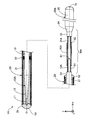
- FIG. 1 is a partial cross-sectional view illustrating the entire configuration of the guidewire 1 according to the first embodiment.
- the guidewire 1 is, for example, a medical device used when inserting a catheter into a blood vessel, and includes a first core shaft 10, a coil body 20, a second core shaft 30, a distal fixing portion 51, and a proximal end. A fixing portion 52 and a covering member 70 are provided.
- an axis passing through the center of the guidewire 1 is represented by an axis O (dashed line).
- axes passing through the centers of the first core shaft 10, the coil body 20, the second core shaft 30, and the covering member 70 all coincide with the axis O. However, the axis passing through the center of each of these members may be different from the axis O.
- FIG. 1 also shows XYZ axes that are orthogonal to each other.
- the X axis corresponds to the axial direction of the guidewire 1
- the Y axis corresponds to the height direction of the guidewire 1
- the Z axis corresponds to the width direction of the guidewire 1.
- the left side ( ⁇ X axis direction) of FIG. 1 is referred to as “the distal end side” of the guidewire 1 and each component
- the right side (+ X axis direction) of FIG. 1 is referred to as the “proximal side” of the guidewire 1 and each component member. Call.
- distal end or simply “distal end”
- base end or simply “proximal end”.
- distal side corresponds to “distal side”
- proximal side corresponds to “proximal side”.
- the first core shaft 10 is an elongated member having a large diameter at the center and a small diameter at both ends (the distal end and the proximal end).
- the first core shaft 10 is formed of a superelastic material, for example, a NiTi (nickel titanium) alloy or an alloy of NiTi and another metal.
- the first core shaft 10 has a distal small-diameter portion 11, a distal reduced-diameter portion 12, a first large-diameter portion 13, and a first small-diameter portion 15 in this order from the distal end side to the proximal end side.
- the outer diameter and length of each part can be arbitrarily determined.
- the distal small diameter portion 11 is disposed at the distal end of the first core shaft 10.
- the distal small-diameter portion 11 is a portion where the outer diameter of the first core shaft 10 is the minimum, and has a substantially cylindrical shape having a constant outer diameter.
- the distal reduced diameter portion 12 is disposed between the distal small diameter portion 11 and the first large diameter portion 13.
- the distal reduced diameter portion 12 has a substantially truncated cone shape whose outer diameter is reduced from the base end toward the distal end.
- the first large diameter portion 13 is arranged between the distal reduced diameter portion 12 and the first small diameter portion 15.
- the first large diameter portion 13 is a portion where the outer diameter of the first core shaft 10 is the largest, and has a substantially cylindrical shape having a constant outer diameter.
- the first small-diameter portion 15 is arranged at a base end of the first core shaft 10.
- the first small-diameter portion 15 has a substantially cylindrical shape having a constant outer diameter smaller than the first large-diameter portion 13 and larger than the tip small-diameter portion 11.
- the second core shaft 30 is a tapered long member having a large diameter at the base end and a small diameter at the distal end.
- the second core shaft 30 is formed of a material having higher rigidity than the first core shaft 10, for example, a stainless alloy such as SUS304 and SUS316.
- the second core shaft 30 includes a second small-diameter portion 31, a second large-diameter portion 33, a proximal reduced-diameter portion 34, and a proximal large-diameter portion 35 in order from the distal end side to the proximal end side. .
- the outer diameter and length of each part can be arbitrarily determined.
- the second small-diameter portion 31 is disposed at the tip of the second core shaft 30.
- the second small-diameter portion 31 is a portion where the outer diameter of the second core shaft 30 is the minimum, and has a substantially columnar shape having a constant outer diameter that is substantially the same as the first small-diameter portion 15 of the first core shaft 10.
- the second large-diameter portion 33 is disposed between the second small-diameter portion 31 and the proximal-end reduced-diameter portion 34.
- the second large-diameter portion 33 has a substantially cylindrical shape that is smaller than the base large-diameter portion 35 and has a constant outer diameter larger than the second small-diameter portion 31.
- the proximal reduced diameter portion 34 is disposed between the second large diameter portion 33 and the proximal large diameter portion 35.
- the proximal reduced diameter portion 34 has a substantially truncated cone shape whose outer diameter is reduced from the proximal end toward the distal end.
- the base end large diameter portion 35 is disposed at the base end of the second core shaft 30.
- the base end large diameter portion 35 is a portion where the outer diameter of the second core shaft 30 is the largest, and has a substantially cylindrical shape having a constant outer diameter.
- the distal end sides of the distal small-diameter portion 11, the distal reduced-diameter portion 12, and the first large-diameter portion 13 are covered with a coil body 20 described later.
- the base end side of the first large diameter portion 13 of the first core shaft 10, the first small diameter portion 15, and each portion of the second core shaft 30 are not covered with the coil body 20, Exposed from 20.
- the proximal large diameter portion 35 of the second core shaft 30 is used when an operator grips the guidewire 1.
- the coil body 20 has a substantially cylindrical shape formed by spirally winding the element wire 21 around the first core shaft 10.
- the wire 21 forming the coil body 20 may be a single wire composed of one wire or a stranded wire obtained by twisting a plurality of wires.
- the coil body 20 is configured as a single coil, and when the wire 21 is a stranded wire, the coil body 20 is configured as a hollow stranded wire coil.
- the coil body 20 may be configured by combining a single coil and a hollow stranded wire coil.
- the wire diameter of the element wire 21 and the average coil diameter of the coil body 20 (the average diameter of the outer and inner diameters of the coil body 20) can be arbitrarily determined.
- the wires 21 are made of, for example, stainless steel alloys such as SUS304 and SUS316, superelastic alloys such as NiTi alloys, piano wires, radiolucent alloys such as nickel-chromium alloys and cobalt alloys, gold, platinum, tungsten, and these elements. (For example, a platinum-nickel alloy) or the like. Note that the wires 21 may be formed of a known material other than the above.
- the distal end side fixing portion 51 is disposed at the distal end of the guide wire 1 and integrally holds the distal end of the distal small diameter portion 11 of the first core shaft 10 and the distal end of the coil body 20.
- the distal end side fixing portion 51 can be formed by an arbitrary bonding agent, for example, a metal solder such as silver brazing, gold brazing, zinc, Sn—Ag alloy, Au—Sn alloy, or an adhesive such as an epoxy adhesive.
- the base-side fixing portion 52 is disposed at a part of the first large-diameter portion 13 of the first core shaft 10 near the base end, and integrally forms the first core shaft 10 and the base end of the coil body 20. keeping.
- the proximal fixing portion 52 can be formed of an arbitrary bonding agent, similarly to the distal fixing portion 51. The same fixing agent may be used for the proximal fixing portion 52 and the distal fixing portion 51, or different bonding agents may be used.
- the intermediate fixing portion 61 integrally holds the coil body 20 and the first core shaft 10 in the vicinity of an intermediate portion of the coil body 20 in the direction of the axis O.
- the intermediate fixing portion 61 can be formed of an arbitrary bonding agent, similarly to the distal fixing portion 51.
- the same fixing agent may be used for the intermediate fixing portion 61 and the distal fixing portion 51, or different bonding agents may be used.
- FIG. 1 one intermediate fixing portion 61 is illustrated, but a plurality of intermediate fixing portions 61 may be provided on the guide wire 1.
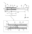
- FIG. 2 is a partial sectional view of 1 pa (FIG. 1) around the contact portion.
- FIG. 2 shows a partial cross-sectional view around the contact portion of the first and second core shafts 10 and 30 in the upper part, and an enlarged view in the vicinity of the covering member 70 in the lower part.
- the XYZ axes shown in FIG. 2 correspond to the XYZ axes in FIG. 1, respectively. This point is the same for the drawings attached with XYZ axes after FIG.
- the first and second core shafts 10 and 30 are arranged facing each other (facing arrangement) with the center axis of the first core shaft 10 and the center axis of the second core shaft 30 aligned with each other. .
- the central axes of the first and second core shafts 10 and 30 coincide with the axis O.
- the center axes of the first and second core shafts 10 and 30 may coincide with each other at a position on the YZ plane different from the axis O.
- the first and second core shafts 10 and 30 may have different center axes.
- a portion where the first and second core shafts 10 and 30 face each other is referred to as a “contact portion CP”.
- the contact portion CP is a portion adjacent to the base end of the first small diameter portion 15 of the first core shaft 10 and the distal end of the second small diameter portion 31 of the second core shaft 30. .
- the first and second core shafts 10 and 30 are joined at the contact portion CP.
- the joining is performed, for example, by joining a gap between the first small-diameter portion 15 of the first core shaft 10 and the second small-diameter portion 31 of the second core shaft 30 that are arranged adjacent to each other at the contact portion CP.
- the embedding can be carried out by filling with agent 81.
- the bonding agent 81 may be disposed on the entire surface with the end surface of the bonding member, or the bonding agent 81 may be disposed only in a part of the gap and the other part may be a void.
- a metal solder such as silver brazing, gold brazing, zinc, Sn—Ag alloy, Au—Sn alloy, or an adhesive such as an epoxy-based adhesive can be used.
- the joining at the contact portion CP may be performed by welding the first and second core shafts 10 and 30.
- the first and second core shafts 10 and 30 need not be joined at the contact portion CP.
- the end surface on the base end side of the first small-diameter portion 15 may be in contact with the end surface on the distal end side of the second small-diameter portion 31.
- the end face on the proximal end side and the end face on the distal end side of the second small-diameter portion 31 may be adjacent to each other via a gap.
- the covering member 70 is a metal tubular member formed in a tubular shape (substantially cylindrical shape) having a constant outer diameter. It is preferable that the covering member 70 has a configuration in which the bending rigidity is lower than that of the second core shaft 30 and has the same elastic modulus as that of the first core shaft 10.
- the covering member 70 can be formed of a superelastic material, for example, a NiTi alloy or an alloy of NiTi and another metal, like the first core shaft 10.
- the covering member 70 may be formed of the same material as the first core shaft 10, or may be formed of a different material.
- the covering member 70 is arranged such that one end (the tip in the illustrated example) of the covering member 70 is located near the boundary 10b between the first large diameter portion 13 and the first small diameter portion 15 of the first core shaft 10. Have been.
- the covering member 70 includes a contact portion CP of the first and second core shafts 10 and 30 and a part of the first core shaft 10 adjacent to the contact portion CP (in the illustrated example, the first small-diameter portion 15). And a part of the second core shaft 30 (in the example shown, a part of the second narrow diameter portion 31 closer to the proximal end than the distal end).
- the first and second core shafts 10 and 30 joined at the contact part CP extend in the direction of the axis O so as to penetrate the lumen of the covering member 70.
- the joining layer 90 is disposed inside the covering member 70, and joins the covering member 70 to the first and second core shafts 10 and 30 (the first small-diameter portion 15 and the second small-diameter portion 31). Holding.
- the bonding layer 90 is formed over the entire gap between the covering member 70 and the first and second core shafts 10 and 30 covered by the covering member 70, and includes the first and second core shafts 10 and 30.
- the diameter part 31 is joined.
- the bonding layer 90 may be formed not on the entire gap between the covering member 70 and the first and second core shafts 10 and 30, but on only a part thereof. When formed in a part, a gap may remain between the covering member 70 and the first and second core shafts 10 and 30.
- the bonding layer 90 can be formed of an arbitrary bonding agent as in the case of the distal end side fixing portion 51. The same bonding agent may be used for the bonding layer 90 and the tip side fixing portion 51, or different bonding agents may be used.
- the length L11 of the first small diameter portion 15 of the first core shaft 10 in the direction of the axis O is the axis O of the second small diameter portion 31 of the second core shaft 30. It is shorter than the length L12 in the direction (L11 ⁇ L12).
- the length L13 of the covering member 70 in the direction of the axis O is greater than the sum of the length L11 of the first small diameter portion 15 in the direction of the axis O and the length L12 of the second small diameter portion 31 in the direction of the axis O. Short (L13 ⁇ L11 + L12).
- the length L13 of the covering member 70 in the direction of the axis O is one of the first and second small-diameter portions 15 and 31 having a shorter length in the direction of the axis O (that is, the length of the first small-diameter portion 15).
- the lengths L11, L12, L13 can be arbitrarily determined as long as the above relation is satisfied.
- the inner diameter D71 of the covering member 70 is larger than the diameter D11 of the first small diameter portion 15 of the first core shaft 10 (D71> D11).
- FIG. 3 is a view for explaining a method of manufacturing the guidewire 1.
- FIG. 3A illustrates the insertion step.
- FIG. 3B shows an arrangement step
- FIG. 3C shows an application step
- FIG. 3D shows a movement step.
- a preparation step a first core shaft 10 having a first large diameter portion 13 and a first small diameter portion 15 and a second core shaft 30 having a second large diameter portion 33 and a second small diameter portion 31 are provided.
- the tubular covering member 70 having the length L13 described above are prepared in advance.
- the covering member 70 is inserted from the second small diameter portion 31 side of the second core shaft 30 (insertion step).
- the covering member 70 is such that the base end of the covering member 70 is located near the boundary 30 b between the second small diameter portion 31 and the second large diameter portion 33 of the second core shaft 30.
- the first small diameter portion 15 of the first core shaft 10 is moved relative to the second small diameter portion 31 of the second core shaft 30 in a state where the covering member 70 is inserted.
- the first and second core shafts 10 and 30 are placed by placing the bonding agent 81 on the portion (contact portion CP) where the first small diameter portion 15 and the second small diameter portion 31 face each other. Join.
- a bonding agent for forming the bonding layer 90 is applied to the surface of the first small-diameter portion 15 and the surface of the tip of the second small-diameter portion 31 (application step).
- the bonding agent is applied to the entire surfaces of the first and second small-diameter portions 15 and 31 exposed from the covering member 70, but the bonding agent is applied to the first and second small-diameter portions 15 and 31. , 31 may be part of the surface.
- the covering member 70 is moved (slid) to the position where the bonding agent forming the bonding layer 90 is applied (moving step).
- the covering member 70 has been moved until the distal end is located near the boundary 10 b between the first large diameter portion 13 and the first small diameter portion 15 of the first core shaft 10.
- the length L13 of the covering member 70 in the direction of the axis O is equal to the length L11 of the first and second small diameter portions 15 and 31 in the direction of the axis O.
- L1 is shorter than the sum of L12 and one of the first and second small diameter portions 15 and 31 is shorter in the direction of the axis O (the length L11 of the first small diameter portion 15 in the above example). It is longer and longer than the other in the direction of the axis O (the length L12 of the second small-diameter portion 31 in the above example) (the upper part in FIG. 2). Therefore, as described with reference to FIG.
- the other of the first and second small diameter portions 15 and 31 having the longer length in the direction of the axis O in a state where the covering member 70 is inserted into the second small-diameter portion 31 (FIG. 3A), the first and second small-diameter portions 15 and 31 are arranged to face each other (FIG. 3B), and the first After applying the bonding agent to the surfaces of the first and second small diameter portions 15 and 31 (FIG. 3C), the covering member 70 is moved to a desired position on the surface of the first and second small diameter portions 15 and 31. (FIG. 3D).
- one end of the shorter one of the first and second small-diameter portions 15 and 31 becomes the larger-diameter portion (in other words, opposite to the contact portion CP).
- the covering member 70 By sliding the covering member 70 to the side end), the covering member 70 can easily cover the contact portion CP of the first and second small diameter portions 15 and 31.
- the damage of the covering member 70 can be suppressed.
- the step of forming a hole in the covering member 70 is not required, the number of manufacturing steps of the guide wire 1 can be reduced.
- one of the first and second small-diameter portions 15 and 31 is short (the first small-diameter portion 15 in the above-described example) on the distal end side of the guidewire 1.
- the material constituting the first core shaft 10 on the distal end side is a material having a lower bending rigidity than the material constituting the second core shaft 30 on the proximal end side. Therefore, the flexibility of the distal end side of the guide wire 1 can be increased.
- the first core shaft 10 located on the distal end side of the guide wire 1 is made of a superelastic alloy such as a NiTi alloy, the distal end side of the guide wire 1 is less likely to be plastically deformed. Can be prevented from being damaged on the tip side.
- the length L13 of the covering member 70 in the direction of the axis O is longer than the length L11 of the first small diameter portion 15 in the direction of the axis O (upper part in FIG. 2). For this reason, at the time of manufacturing the guide wire 1, after applying a bonding agent to the surfaces of the first and second small diameter portions 15 and 31, as shown in FIG. By moving the covering member 70 to the end portion (that is, the tip portion) opposite to the portion CP, a configuration in which the contact portion CP and the vicinity thereof are covered with the covering member 70 can be easily obtained.
- the bonding layer 90 includes the contact portion CP, the first core shaft 10 (the first small diameter portion 15), and the second core shaft inside the covering member 70. 30 (second small diameter portion 31) (FIG. 2, upper part). For this reason, operations such as a rotation operation and a pushing operation on the guide wire 1 at the hand portion (FIG. 1: base end large diameter portion 35) can be transmitted to the distal end side of the guide wire 1. Torque transmission and pushability (operability) can be improved. Further, as in the above-described embodiment, even when the rigidity of the first and second core shafts 10 and 30 is different due to the difference in the material of the first and second core shafts 10 and 30, etc.
- the rigid gap between the first and second core shafts 10 and 30 can be reduced by the covering member 70. For this reason, deformation (bending, twisting, crushing) of the first and second core shafts 10 and 30 in the vicinity of the contact portion CP can be suppressed, and the kink resistance of the guidewire 1 can be improved.
- the covering member 70 by forming the covering member 70 into a tubular shape of a superelastic material, the effect of relaxing the rigid gap by the covering member 70 can be further enhanced, and the resistance of the guidewire 1 can be improved.
- the kink property can be further improved.
- the first core shaft 10 from a superelastic material, flexibility and restorability against bending can be improved, and the second core shaft 30 is made of a material having higher rigidity than the first core shaft 10.
- the outer diameter D72 of the covering member 70 is substantially the same as the diameter D12 of the first large-diameter portion 13 of the first core shaft 10 (the lower part in FIG. 2).
- the surface shape of the connection portion between the first core shaft 10 and the covering member 70 can be made a flat shape without unevenness, and when pushing a medical device such as a balloon catheter through the guide wire 1, The medical device can be prevented from being caught, and as a result, the medical device can be prevented from being damaged.
- FIG. 4 is a partial cross-sectional view illustrating the entire configuration of the guidewire 1A according to the second embodiment.
- FIG. 5 is a partial cross-sectional view of 1pa (FIG. 4) around the contact portion according to the second embodiment.
- the configuration in the upper and lower stages in FIG. 5 is the same as that in FIG.
- the arrangement of the covering member 70A mainly in the direction of the axis O is different from that of the first embodiment.
- the covering member 70A is disposed so as to be located near the center between the first small diameter portion 15A of the first core shaft 10A and the second small diameter portion 31A of the second core shaft 30A joined at the contact portion CPA. Have been.
- the distal end of the covering member 70A is arranged at a distance from the vicinity of the boundary between the first large-diameter portion 13 and the first small-diameter portion 15A of the first core shaft 10A at a distance in the direction of the axis O.
- the base end of the covering member 70A is disposed at a distance in the direction of the axis O from near the boundary between the second large diameter portion 33 and the second small diameter portion 31A of the second core shaft 30A.
- the covering member 70A includes a contact portion CPA of the first and second core shafts 10A and 30A, and a portion of the first core shaft 10A adjacent to the contact portion CPA (in the illustrated example, A portion of the first small diameter portion 15A closer to the distal end than the base end and a portion of the second core shaft 30A (in the illustrated example, a portion closer to the proximal end than the distal end of the second small diameter portion 31A).
- Each is covering.
- the guide wire 1A includes two joining layers 91 and 92 in place of the joining layer 90 of the first embodiment.
- the joining layer 91 joins a part of the distal end side of the covering member 70A and the first core shaft 10A (the first small diameter portion 15A) inside the covering member 70A.
- the joining layer 92 joins a part of the base end of the covering member 70A and the second core shaft 30A (the second small diameter portion 31A) inside the covering member 70A.
- the bonding layers 91 and 92 are formed only at both ends of the covering member 70A in the direction of the axis O, and are not formed near the center of the covering member 70A.
- the bonding layer 91 and the bonding layer 92 can be formed with an arbitrary bonding agent as in the case of the distal end side fixing portion 51.
- the same bonding agent may be used for the bonding layer 91 and the bonding layer 92 and the front-side fixing portion 51, or different bonding agents may be used.
- the length L21 of the first small-diameter portion 15A of the first core shaft 10A in the axis O direction is the second core shaft 30A. Is smaller than the length L22 of the second small diameter portion 31A in the direction of the axis O (L21 ⁇ L22).
- the length L23 of the covering member 70A in the direction of the axis O is greater than the sum of the length L21 of the first small diameter portion 15A in the direction of the axis O and the length L22 of the second small diameter portion 31A in the direction of the axis O. Short (L23 ⁇ L21 + L22).
- the length L23 of the covering member 70A in the direction of the axis O is one of the first and second small-diameter portions 15A and 31A whose length in the direction of the axis O is shorter (the length L21 of the first small-diameter portion 15A). (L23> L21).
- the lengths L21, L22, L23 can be arbitrarily determined as long as the above relationship is satisfied.
- the relationship between the inner diameter D71 and outer diameter D72 of the covering member 70A, the diameter D11 of the first small diameter portion 15A, and the diameter D12 of the first large diameter portion 13 is also the same as in the first embodiment.
- FIG. 6 is a diagram illustrating a method of manufacturing the guidewire 1A according to the second embodiment.
- FIG. 6A illustrates the insertion step.
- FIG. 6B shows an arrangement step
- FIG. 6C shows a first coating step
- FIG. 6D shows a first moving step and a second coating step
- FIG. Each of the moving steps is illustrated.
- the preparation step, the insertion step, and the arrangement step are the same as in the first embodiment described with reference to FIG.
- a bonding agent for forming the bonding layer 91 is applied to the surface of the first small-diameter portion 15A exposed from the covering member 70A (first application step). ).
- the bonding agent is applied to the entire surface of the first small diameter portion 15A exposed from the covering member 70A.
- the application of the bonding agent may be a part of the surface of the first small diameter portion 15A.
- the covering member 70A is moved (slid) to a position where the bonding agent for forming the bonding layer 91 is applied (first moving step). .
- the covering member 70A has been moved until the distal end is located near the boundary 10b between the first large diameter portion 13 and the first small diameter portion 15A.
- a bonding agent for forming the bonding layer 92 is applied to the surface of the second small-diameter portion 31A exposed from the covering member 70A after the movement (second coating step).
- the bonding agent is applied to the entire surface of the second small diameter portion 31A exposed from the covering member 70A, but the application of the bonding agent may be a part of the surface of the second small diameter portion 31A.
- the covering member 70A is moved to the vicinity of the center between the first small diameter portion 15A and the second small diameter portion 31A (second movement step).
- the covering member 70A may be disposed at a distance in the direction of the axis O from the vicinity of the boundary between the large diameter portion and the small diameter portion of the first and second core shafts 10A and 30A. May not necessarily be located near the center of the first and second small diameter portions 15A and 31A. Further, the covering member 70A may be joined to the first and second core shafts 10A and 30A by providing a gap between the inner surface and the outer surface (surface) of the first and second core shafts 30A and 30A.
- the guide wire 1A according to the second embodiment can also provide the same effects as the first embodiment. That is, in the guide wire 1A including the first and second core shafts 10A and 30A covered by the covering member 70A, it is possible to suppress the breakage of the covering member 70A, and it is unnecessary to form a hole in the covering member 70A. Therefore, the man-hour for manufacturing the guide wire 1A can be reduced. Further, according to the guide wire 1A of the second embodiment, the two joining layers 91 and 92 are formed on the inside of the covering member 70A at both ends of the covering member 70A and the first and second small-diameter portions.
- the operation of the guide wire 1A at the hand portion can be transmitted to the distal end side, and the torque transmission and push-in (operability) of the guide wire 1A can be improved. Further, even when the first and second core shafts 10A and 30A have different rigidities, the rigidity gap can be reduced by the covering member 70A, so that the first and second core shafts in the vicinity of the contact portion CPA can be reduced. The deformation of the core shafts 10A and 30A can be suppressed, and the kink resistance of the guide wire 1A can be improved.
- FIG. 7 is a partial cross-sectional view illustrating the entire configuration of the guidewire 1B according to the third embodiment.
- FIG. 8 is a partial cross-sectional view of 1pa (FIG. 7) around the contact portion according to the third embodiment.
- the configuration of the upper and lower stages in FIG. 8 is the same as that in FIG.
- the guide wire 1B according to the third embodiment is different from the first embodiment in the configuration of the first and second core shafts 10B and 30B in the vicinity of the contact portion 1pa. 40 is provided.
- the first small-diameter portion 15 includes a first end-side small-diameter portion 15e and a first intermediate small-diameter portion 15m.
- the first end side small diameter portion 15e is provided on the base end side of the first core shaft 10B, and has a substantially cylindrical shape having a constant outer diameter smaller than the first intermediate small diameter portion 15m.
- the first intermediate small-diameter portion 15m is provided between the first end-side small-diameter portion 15e and the first large-diameter portion 13, is thicker than the first end-side small-diameter portion 15e, and has a first large-diameter portion. It has a substantially cylindrical shape with a constant outer diameter smaller than 13.
- the second small diameter portion 31 includes a second end side small diameter portion 31e and a second intermediate small diameter portion 31m.
- the second end side small diameter portion 31e is provided on the distal end side of the second core shaft 30B, and has a substantially cylindrical shape having a constant outer diameter smaller than the second intermediate small diameter portion 31m.
- the second intermediate small-diameter portion 31m is provided between the second end-side small-diameter portion 31e and the second large-diameter portion 33, is thicker than the second end-side small-diameter portion 31e, and has a second large-diameter portion. It has a substantially cylindrical shape with a constant outer diameter smaller than 33.
- the proximal end surface of the first end-side small-diameter portion 15e of the first core shaft 10B and the second end-side small diameter of the second core shaft 30B is disposed adjacent to the end face.
- the first and second core shafts 10B and 30B are joined.
- various modes can be adopted for this bonding, and the bonding may be omitted.
- the inner covering member 40 is a metal tubular member formed in a tubular shape (substantially cylindrical shape) having a constant outer diameter.
- the inner covering member 40 of the present embodiment is configured to have lower bending rigidity than the second core shaft 30B, and have the same elastic modulus as the first core shaft 10B.
- the inner covering member 40 can be formed of a superelastic material, for example, a NiTi alloy or an alloy of NiTi and another metal.
- the inner covering member 40 may be formed of the same material as the covering member 70, or may be formed of a different material.
- the inner covering member 40 includes a contact portion CPB and a part of the first core shaft 10B adjacent to the contact portion CPB (in the illustrated example, the first end side small diameter portion 15e) inside the covering member 70. , And a part of the second core shaft 30B adjacent to the contact part CPB (in the illustrated example, the second end-side small-diameter part 31e) is disposed to cover each part.
- the length of the inner covering member 40B in the direction of the axis O is the length of the first end-side small-diameter portion 15e in the direction of the axis O, and the length of the second end-side small-diameter portion 31e in the direction of the axis O. It is almost equal to the sum of Note that the length of the inner covering member 40D can be arbitrarily determined.
- the inner covering member 40 includes the first and second core shafts 10 ⁇ / b> B and 30 ⁇ / b> B (the first end side small diameter portion 15 e and the second end side small diameter portion) by the bonding layer 93 disposed inside the inner covering member 40. 31e).
- the bonding layer 93 is formed at the first end portion of the gap between the inner coating member 40 and the first and second end-side small-diameter portions 15 e and 31 e covered by the inner coating member 40. It is formed substantially entirely except for the distal end of the side small diameter portion 15e and the base end of the second end side small diameter portion 31e.
- the bonding layer 93 can be formed of an arbitrary bonding agent as in the case of the distal end side fixing portion 51.
- the same bonding agent may be used for the bonding layer 93 and the tip side fixing portion 51, or different bonding agents may be used.
- the first small-diameter portion 15 of the first core shaft 10B (that is, the first end-side small-diameter portion 15e and the first
- the length L31 of the intermediate small-diameter portion 15m) in the direction of the axis O is the length of the second small-diameter portion 31 of the second core shaft 30B (that is, the second end-side small-diameter portion 31e and the second intermediate small-diameter portion 31m). It is shorter than the length L32 in the direction of the axis O (L31 ⁇ L32).
- the relationship between the length L33 of the covering member 70 in the direction of the axis O and the lengths L31 and L32 is the same as in the first embodiment (L33 ⁇ L31 + L32, L33> L31).
- the lengths L31, 32, and 33 can be arbitrarily determined as long as the above relationship is satisfied.
- the inner covering member 40 may be further provided inside the covering member 70.
- the first small-diameter portion 15 of the first core shaft 10B and the second small-diameter portion 31 of the second core shaft 30B may be configured by two or more plural small-diameter portions.
- the guide wire 1B of the third embodiment can be manufactured by the same method as that of the first embodiment described with reference to FIG.
- the guide wire 1 ⁇ / b> B of the third embodiment can also provide the same effects as those of the first embodiment.
- the contact portion CPB and the first and second end-side small-diameter portions 15e and 31e adjacent to the contact portion CPB are provided inside the covering member 70.
- the inner covering member 40 is disposed to cover the inside. For this reason, even when the rigidity of the first and second core shafts 10B, 30B is different from each other, the rigid gap between the first and second core shafts 10B, 30B can be reduced by the inner covering member 40. .
- the inner covering member 40 can reduce the rigidity gap. For this reason, the deformation of the first and second core shafts 10B and 30B near the contact portion CPB and the deformation of the first and second core shafts 10B and 30B near the inner covering member 40 can be suppressed, and the guide wire can be suppressed.
- the kink resistance of 1B can be further improved.
- the outer diameter of the inner covering member 40 and the outer diameter of each of the first and second core shafts 10B and 30B are made to match each other, so that the first end of the first core shaft 10B is narrowed. It is possible to suppress the influence of the processing accuracy of the diameter portion 15e and the second end side small diameter portion 31e of the second core shaft 30B on the disturbance of rotation.
- the outer diameter of the inner covering member 40 and the first and second core shafts 10B and 30B have an integral structure, it is possible to suppress the ripple of the covering member 70 from being disturbed due to the inner surface processing accuracy.
- the guide wire is provided. It is possible to suppress the disturbance of the rotation of the first core shaft 10B of 1B.
- FIG. 9 is a partial cross-sectional view around the contact portion of the guide wire 1C according to the fourth embodiment.
- the configuration of the upper and lower stages in FIG. 9 is the same as that of FIG.
- the guide wire 1C of the fourth embodiment has an inner coating member 40C having a different configuration from the third embodiment in the configuration of the third embodiment.
- FIG. 10 is a perspective view showing a schematic configuration of the inner covering member 40C.
- the inner covering member 40C is a multi-strand coil formed by winding eight wires 41 in a multi-strand pattern, and has a substantially cylindrical shape having a constant outer diameter.
- the inner covering member 40C is preferably configured to have a lower bending rigidity than the second core shaft 30B.
- the inner covering member 40C is formed, for example, by tightly twisting eight wires 41 on a metal core so as to be in contact with each other, then removing the residual stress using a known heat treatment method, and extracting the metal core. Can be formed.
- the inner covering member 40C formed as described above becomes a multi-row coil having a lumen 40h (FIG. 10: broken line).
- the material of the strand 41 may be the same as the strand 21 or may be different.
- the inner covering member 40C can employ any mode.
- the number of wires constituting the inner covering member 40C is not limited to eight, and can be arbitrarily determined.
- the inner covering member 40C is not limited to the multi-layer coil, and may be a single-layer coil formed using one strand, and may be a resin material having hydrophobicity, a resin material having hydrophilicity, or a mixture thereof. May be coated.
- the inner covering member 40C various configurations may be adopted for the inner covering member 40C.
- the same effect as in the first and third embodiments can also be obtained in the guide wire 1C according to the fourth embodiment.
- the bonding agent arranged to form the bonding layer 90 is provided inside the coating member 70 with the gap between the wires of the inner coating member 40C and the inner coating member 40C. , It is possible to join the inner covering member 40C to the first and second core shafts 10B and 30B.
- the first and second core shafts 10B and 30B facilitate dispersion.
- FIG. 11 is a partial cross-sectional view around the contact portion of the guide wire 1D according to the fifth embodiment.
- the configuration of the upper and lower stages in FIG. 11 is the same as that of FIG.
- the guide wire 1D of the fifth embodiment has an inner fixing portion 95 for fixing the inner coating member 40C to the first and second core shafts 10B and 30B in the configuration of the fourth embodiment.
- the inner fixing portion 95 is disposed so as to cover the inner coating member 40C, and includes a first end-side small-diameter portion 15e of the first core shaft 10B and a second end-side small-diameter portion 31e of the second core shaft 30B.
- the inner covering member 40C are integrally fixed.
- the inner fixing portion 95 can be formed of an arbitrary bonding agent, similarly to the distal fixing portion 51. The same fixing agent may be used for the inner fixing portion 95 and the front fixing portion 51, or different bonding agents may be used.
- the inner coating member 40C and the coating member 70 may be individually fixed to the first and second core shafts 10B and 30B, respectively.
- the same effect as in the first and third embodiments can be obtained in the guide wire 1D of the fifth embodiment. Further, the same effects as in the fourth embodiment regarding stress dispersion can be obtained.
- the step of fixing the inner covering member 40C to the first and second core shafts 10B and 30B (forming the inner fixing portion 95); And fixing the covering member 70C to the first and second core shafts 10B and 30B (forming the bonding layer 90) can be performed independently.
- FIG. 12 is a partial cross-sectional view around a contact portion of a guide wire 1E according to a sixth embodiment.
- substantially the same length including the error range is also included in the “equal length”.
- the length L63 of the covering member 70 in the direction of the axis O is equal to the length L61 of the first small-diameter portion 15E in the direction of the axis O, and the length of the second small-diameter portion. It is shorter than the sum of the length L62 of the portion 31E in the direction of the axis O (L63 ⁇ L61 + L62). Furthermore, the length L63 of the covering member 70 in the direction of the axis O is longer than the length L61 of the first small diameter portion 15E in the direction of the axis O (L63> L61), and the length of the second small diameter portion 31E in the direction of the axis O. It is longer than L62 (L63> L62). Note that the lengths L61, 62, and 63 can be arbitrarily determined as long as the above relationship is satisfied.
- the lengths of the first and second small-diameter portions 15E and 31E of the first and second core shafts 10E and 30E in the direction of the axis O may be substantially the same. Also in such a sixth embodiment, the same effects as in the first embodiment can be obtained. According to the guide wire 1E of the sixth embodiment, the first and second small-diameter portions 15E and 31E have the same length in the direction of the axis O, so that the manufacture of the first and second core shafts 10E and 30E is easy. It is.
- FIG. 13 is a partial cross-sectional view around the contact portion of the guide wire 1F according to the seventh embodiment.
- the guide wire 1F of the seventh embodiment is different from the first embodiment in that the relationship between the lengths of the first and second small diameter portions 15F, 31F of the first and second core shafts 10F, 30F in the axis O direction is different from that of the first embodiment.
- the opposite is true. That is, the length L71 of the first small diameter portion 15F of the first core shaft 10F in the axis O direction is longer than the length L72 of the second small diameter portion 31F of the second core shaft 30F in the axis O direction (L71> L72). ).
- the length L73 of the covering member 70 in the direction of the axis O is shorter than the sum of the lengths L71 and L72 (L73 ⁇ L71 + L72), and is the length of the first and second small-diameter portions 15F and 31F in the direction of the axis O. Is longer (L73> L72) than the shorter one (that is, the length L72 of the second small diameter portion 31F). Note that the lengths L71, 72, 73 can be arbitrarily determined as long as the above relation is satisfied.
- the coating member 70 is configured such that one end (the base end in the illustrated example) of the coating member 70 is connected to the second small diameter portion 31F and the second large diameter portion 33 of the second core shaft 30F. Are arranged so as to be located near the boundary 30b.
- the covering member 70 includes a contact portion CPF of the first and second core shafts 10F and 30F and a part of the first and second core shafts 10F and 30F adjacent to the contact portion CPF. Is covered.
- the guide wire 1F of the seventh embodiment in the manufacturing method described with reference to FIG. 3, “the first small-diameter portion 15 of the first core shaft 10” is replaced with “the second small-diameter portion 31F of the second core shaft 30F”. , "The second small diameter portion 31 of the second core shaft 30" may be read as "the first small diameter portion 15F of the first core shaft 10F".
- the length of the first and second core shafts 10F, 30F in the direction of the axis O of the first and second small-diameter portions 15F, 31F can be arbitrarily determined, and the base end of the guide wire 1F.
- the second core shaft 30F located on the side may be shortened. Also in the seventh embodiment, the same effects as in the first embodiment can be obtained.
- FIG. 14 is a partial cross-sectional view around the contact portion of the guide wire 1G according to the eighth embodiment.
- first and second core shafts 10G and 30G include first and second intermediate portions 14 and 32, respectively.
- the first intermediate portion 14 is formed between the first large diameter portion 13 and the first small diameter portion 15 in the first core shaft 10G.
- the first intermediate portion 14 has a substantially truncated cone shape whose outer diameter increases from the base end side toward the distal end side.
- the second intermediate portion 32 is formed between the second large diameter portion 33 and the second small diameter portion 31 in the second core shaft 30G.
- the second intermediate portion 32 has a substantially truncated conical shape in which the outer diameter decreases from the base end side toward the distal end side.
- the “near the boundaries 10b and 30b” described in the first embodiment includes the first and second intermediate portions 14 and 32.
- the covering member 70 may be arranged such that the distal end of the covering member 70 is located at the base end of the first intermediate portion 14 as illustrated.
- the covering member 70 may be arranged such that the distal end of the covering member 70 is located substantially at the center of the first intermediate portion 14 in the direction of the axis O, or may be arranged at the distal end of the first intermediate portion 14.
- the configuration of the first and second core shafts 10G, 30G can be arbitrarily changed. The same effect as in the first embodiment can be obtained in the guide wire 1G of the eighth embodiment.
- FIG. 15 is a partial cross-sectional view around the contact portion of the guide wire 1H according to the ninth embodiment.
- the guide wire 1H of the ninth embodiment has a bonding layer 90H instead of the bonding layer 90 in the configuration of the first embodiment.
- the bonding layer 90H is formed in a part of a gap between the covering member 70 and the first and second core shafts 10 and 30 covered by the covering member 70.
- the bonding layer 90H is formed at substantially the center of the above-described gap in the direction of the axis O of the covering member 70, and is not formed at both ends (the distal end and the base end).
- a void in which the bonding layer 90H is not formed remains inside both ends of the covering member 70.
- the range in which the bonding layer 90H is formed can be arbitrarily changed.
- the same effect as in the first embodiment can be obtained.
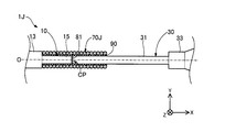
- FIG. 16 is a partial cross-sectional view around the contact portion of the guide wire 1J according to the tenth embodiment.
- the guide wire 1J of the tenth embodiment includes a covering member 70J having a configuration different from that of the covering member 70 in the configuration of the first embodiment.
- the covering member 70J is a substantially cylindrical coil body formed by spirally winding an element wire.
- the covering member 70J may be a single coil composed of one strand, or a hollow stranded coil composed of a stranded wire using a plurality of strands. Further, the covering member 70J may be the multi-row coil described with reference to FIG.
- the material of the wires constituting the covering member 70J may be the same as or different from the wires 21 of the coil body 20.
- the shape of the covering member 70J is not limited to the tubular shape and can be arbitrarily changed.
- the guide wire 1J of the tenth embodiment can also provide the same effects as those of the first and fourth embodiments.
- FIG. 17 is an enlarged view near the covering member 70 of the guide wire 1K according to the eleventh embodiment.
- the guide wire 1K of the eleventh embodiment includes an inner coating member 40K having a configuration different from that of the inner coating member 40 in the configuration of the third embodiment.
- the inner covering member 40K is a metal tubular member formed in a tubular shape (substantially cylindrical shape) having a constant outer diameter, similarly to the covering member 70.
- the inner covering member 40K may be formed of the same material as the covering member 70, or may be formed of a different material.
- the distal end side of the inner covering member 40K is fixed to the first end side small diameter portion 15e of the first core shaft 10B by caulking the distal end portion 40d.
- the base end side of the inner covering member 40K is fixed to the second end side narrow portion 31e of the second core shaft 30B by caulking the base end 40p.
- the inside of the inner covering member 40K is a space where the bonding agent is not arranged.
- the inner covering member 40K may be fixed to the first and second core shafts 10B and 30B by a method other than the bonding agent. The same effect as in the first and third embodiments can be obtained also in the guidewire 1K of the eleventh embodiment.
- the configurations of the guide wires 1 and 1A to 1K have been exemplified.
- the configuration of the guide wire can be variously changed.
- the guidewire of each of the above embodiments has been described as a medical device used when inserting a catheter into a blood vessel, but the lymph gland system, biliary system, urinary system, respiratory system, digestive system, secretory gland and It can also be configured as a guidewire inserted into each organ in the human body such as a reproductive organ.
- the guide wire has a configuration in which the entirety of the first and second core shafts (in other words, the entirety from the distal end of the first core shaft to the proximal end of the second core shaft) is covered by the coil body. You may.
- the guide wire may be commercialized in a state where the distal end side is curved in advance.
- the configuration of the first and second core shafts 10, 10A, 10B, 10E to 10G, 30, 30A, 30B, 30E to 30G has been exemplified.
- the configurations of the first core shaft and the second core shaft can be variously changed.
- the first core shaft does not have to have the distal small diameter portion or the distal reduced diameter portion
- the second core shaft does not have to have the proximal reduced diameter portion or the proximal large diameter portion.
- the first core shaft may be formed of various materials other than the superelastic material
- the second core shaft may be formed of a material that is less plastically deformed than the first core shaft.
- the first and second core shafts may be formed of the same material.
- the cross-sectional shape of each part of the first and second core shafts need not be a substantially circular shape, and various shapes (for example, a substantially rectangular shape, a substantially elliptical shape, and the like) can be adopted.
- the configuration of the coil body 20 has been described.
- the configuration of the coil body can be variously changed.
- the coil body may be configured in a tightly wound state with no gap between adjacent strands, may be formed in a loosely wound state with a gap between adjacent strands, or may be formed in a tightly wound state with a gap between adjacent strands.
- a configuration in which winding is mixed may be employed.
- the coil body may include, for example, a resin layer coated with a hydrophobic resin material, a hydrophilic resin material, or a mixture thereof.
- the cross-sectional shape of the element wire of the coil body need not be substantially circular.
- the inner covering member may be formed of a material other than metal (for example, resin).
- the inner covering member may be provided with an underlayer for facilitating adhesion of the bonding agent.
- the cross-sectional shape may be an elliptical cylindrical shape.
- the cross-sectional shape of the wire need not be substantially circular, and a shape such as a substantially elliptical shape or a substantially rectangular shape can be adopted.
- the covering member may be formed of a material other than metal (for example, resin or the like).
- the covering member may have a configuration in which the bending rigidity is substantially the same or higher than that of the second core shaft, or may have a configuration having a different elastic modulus from that of the first core shaft.
- the first and second intermediate portions described in the eighth embodiment are used.
- a configuration including a portion may be employed, and the bonding layer described in the ninth embodiment may be employed.
- Tip side fixing part 52 Base end side fixing part 61 ... Intermediate fixing part 70, 70A, 70C, 70J ... Coating member 81 ... Bonding agent 90,90 H: bonding layer 91, 92, 93: bonding layer 95: inner fixed portion
Landscapes
- Health & Medical Sciences (AREA)
- Life Sciences & Earth Sciences (AREA)
- Biophysics (AREA)
- Pulmonology (AREA)
- Engineering & Computer Science (AREA)
- Anesthesiology (AREA)
- Biomedical Technology (AREA)
- Heart & Thoracic Surgery (AREA)
- Hematology (AREA)
- Animal Behavior & Ethology (AREA)
- General Health & Medical Sciences (AREA)
- Public Health (AREA)
- Veterinary Medicine (AREA)
- Media Introduction/Drainage Providing Device (AREA)
Abstract
Fil-guide comprenant une première âme centrale, une seconde âme centrale, un élément de revêtement et une couche de jonction. La première âme centrale comporte une première section de grand diamètre et une première section de petit diamètre, et la seconde âme centrale comporte une seconde section de grand diamètre et une seconde section de petit diamètre. L'élément de revêtement recouvre une section de positionnement de contact, dans laquelle les première et seconde sections de petit diamètre sont positionnées de manière à se faire face, et au moins une partie de chacune des première et seconde sections de petit diamètre est adjacente à la section de positionnement de contact. La couche de jonction relie le matériau de revêtement, la première section de petit diamètre et la seconde section de petit diamètre au niveau de l'intérieur du matériau de revêtement. La longueur dans la direction axiale de l'élément de revêtement est plus courte que la somme des longueurs respectives dans la direction axiale des première et seconde sections de petit diamètre, et est plus longue que la longueur dans la direction axiale la plus courte parmi les première et seconde sections de petit diamètre.
Priority Applications (5)
| Application Number | Priority Date | Filing Date | Title |
|---|---|---|---|
| JP2020530805A JP7175311B2 (ja) | 2018-07-19 | 2018-07-19 | ガイドワイヤ及びガイドワイヤを製造する方法 |
| CN201880095113.0A CN112368043B (zh) | 2018-07-19 | 2018-07-19 | 导丝及制造导丝的方法 |
| PCT/JP2018/027068 WO2020016986A1 (fr) | 2018-07-19 | 2018-07-19 | Fil-guide et procédé de fabrication de fil-guide |
| EP18927045.7A EP3824938A4 (fr) | 2018-07-19 | 2018-07-19 | Fil-guide et procédé de fabrication de fil-guide |
| US17/150,019 US20210128887A1 (en) | 2018-07-19 | 2021-01-15 | Guide wire, and guide wire manufacturing method |
Applications Claiming Priority (1)
| Application Number | Priority Date | Filing Date | Title |
|---|---|---|---|
| PCT/JP2018/027068 WO2020016986A1 (fr) | 2018-07-19 | 2018-07-19 | Fil-guide et procédé de fabrication de fil-guide |
Related Child Applications (1)
| Application Number | Title | Priority Date | Filing Date |
|---|---|---|---|
| US17/150,019 Continuation US20210128887A1 (en) | 2018-07-19 | 2021-01-15 | Guide wire, and guide wire manufacturing method |
Publications (1)
| Publication Number | Publication Date |
|---|---|
| WO2020016986A1 true WO2020016986A1 (fr) | 2020-01-23 |
Family
ID=69164848
Family Applications (1)
| Application Number | Title | Priority Date | Filing Date |
|---|---|---|---|
| PCT/JP2018/027068 Ceased WO2020016986A1 (fr) | 2018-07-19 | 2018-07-19 | Fil-guide et procédé de fabrication de fil-guide |
Country Status (5)
| Country | Link |
|---|---|
| US (1) | US20210128887A1 (fr) |
| EP (1) | EP3824938A4 (fr) |
| JP (1) | JP7175311B2 (fr) |
| CN (1) | CN112368043B (fr) |
| WO (1) | WO2020016986A1 (fr) |
Cited By (2)
| Publication number | Priority date | Publication date | Assignee | Title |
|---|---|---|---|---|
| WO2022264669A1 (fr) * | 2021-06-14 | 2022-12-22 | 朝日インテック株式会社 | Fil guide |
| WO2025100048A1 (fr) * | 2023-11-09 | 2025-05-15 | 朝日インテック株式会社 | Fil-guide |
Families Citing this family (2)
| Publication number | Priority date | Publication date | Assignee | Title |
|---|---|---|---|---|
| CN115055771B (zh) * | 2021-10-22 | 2024-03-01 | 美度可医疗科技(上海)有限公司 | 一种安全性能和操作性能高的导丝及焊接方法 |
| CN119679546B (zh) * | 2025-02-25 | 2025-05-02 | 北京华脉泰科医疗器械股份有限公司 | 主动脉覆膜支架原位开窗破膜系统 |
Citations (5)
| Publication number | Priority date | Publication date | Assignee | Title |
|---|---|---|---|---|
| JPH1157014A (ja) * | 1997-08-11 | 1999-03-02 | Terumo Corp | ガイドワイヤ |
| US6602208B2 (en) | 1997-10-10 | 2003-08-05 | Advanced Cardiovascular Systems, Inc. | Guidewire with tubular connector |
| JP2004016359A (ja) | 2002-06-13 | 2004-01-22 | Terumo Corp | ガイドワイヤ |
| JP2008161589A (ja) * | 2006-12-28 | 2008-07-17 | Terumo Corp | ガイドワイヤ |
| JP2017513604A (ja) | 2014-04-21 | 2017-06-01 | コーニンクレッカ フィリップス エヌ ヴェKoninklijke Philips N.V. | 係合されるコア要素を伴う別々のセクションを有する血管内デバイス、システム及び方法 |
Family Cites Families (13)
| Publication number | Priority date | Publication date | Assignee | Title |
|---|---|---|---|---|
| US5109867A (en) * | 1991-04-19 | 1992-05-05 | Target Therapeutics | Extendable guidewire assembly |
| US6001068A (en) * | 1996-10-22 | 1999-12-14 | Terumo Kabushiki Kaisha | Guide wire having tubular connector with helical slits |
| DE60208057T2 (de) * | 2001-10-05 | 2006-06-29 | Boston Scientific Ltd. | Kompositführungsdraht |
| US6866642B2 (en) * | 2002-11-25 | 2005-03-15 | Advanced Cardiovascular Systems, Inc. | Enhanced method for joining two core wires |
| US7182735B2 (en) * | 2003-02-26 | 2007-02-27 | Scimed Life Systems, Inc. | Elongated intracorporal medical device |
| US20040167441A1 (en) * | 2003-02-26 | 2004-08-26 | Reynolds Brian R. | Composite medical device |
| JP2006122311A (ja) * | 2004-10-28 | 2006-05-18 | Tokusen Kogyo Co Ltd | ガイドワイヤ |
| JP4829684B2 (ja) * | 2006-06-02 | 2011-12-07 | 株式会社エフエムディ | 医療用ガイドワイヤ |
| US8206837B2 (en) * | 2007-01-12 | 2012-06-26 | Terumo Kabushiki Kaisha | Interventional medical device |
| JP2014100300A (ja) * | 2012-11-20 | 2014-06-05 | Asahi Intecc Co Ltd | ガイドワイヤ |
| US20150094690A1 (en) * | 2013-09-30 | 2015-04-02 | Abbott Cardiovasular Systems Inc. | Guidewire with varying properties |
| US10071229B2 (en) * | 2015-04-14 | 2018-09-11 | Abbott Cardiovascular Systems, Inc. | Mechanisms for improving the stiffness transition across a dissimilar metal weld joint |
| JP6399460B2 (ja) * | 2016-09-30 | 2018-10-03 | 株式会社エフエムディ | 医療用ガイドワイヤ |
-
2018
- 2018-07-19 EP EP18927045.7A patent/EP3824938A4/fr active Pending
- 2018-07-19 CN CN201880095113.0A patent/CN112368043B/zh active Active
- 2018-07-19 JP JP2020530805A patent/JP7175311B2/ja active Active
- 2018-07-19 WO PCT/JP2018/027068 patent/WO2020016986A1/fr not_active Ceased
-
2021
- 2021-01-15 US US17/150,019 patent/US20210128887A1/en active Pending
Patent Citations (5)
| Publication number | Priority date | Publication date | Assignee | Title |
|---|---|---|---|---|
| JPH1157014A (ja) * | 1997-08-11 | 1999-03-02 | Terumo Corp | ガイドワイヤ |
| US6602208B2 (en) | 1997-10-10 | 2003-08-05 | Advanced Cardiovascular Systems, Inc. | Guidewire with tubular connector |
| JP2004016359A (ja) | 2002-06-13 | 2004-01-22 | Terumo Corp | ガイドワイヤ |
| JP2008161589A (ja) * | 2006-12-28 | 2008-07-17 | Terumo Corp | ガイドワイヤ |
| JP2017513604A (ja) | 2014-04-21 | 2017-06-01 | コーニンクレッカ フィリップス エヌ ヴェKoninklijke Philips N.V. | 係合されるコア要素を伴う別々のセクションを有する血管内デバイス、システム及び方法 |
Non-Patent Citations (1)
| Title |
|---|
| See also references of EP3824938A4 |
Cited By (3)
| Publication number | Priority date | Publication date | Assignee | Title |
|---|---|---|---|---|
| WO2022264669A1 (fr) * | 2021-06-14 | 2022-12-22 | 朝日インテック株式会社 | Fil guide |
| JP2022190427A (ja) * | 2021-06-14 | 2022-12-26 | 朝日インテック株式会社 | ガイドワイヤ |
| WO2025100048A1 (fr) * | 2023-11-09 | 2025-05-15 | 朝日インテック株式会社 | Fil-guide |
Also Published As
| Publication number | Publication date |
|---|---|
| EP3824938A1 (fr) | 2021-05-26 |
| US20210128887A1 (en) | 2021-05-06 |
| CN112368043B (zh) | 2023-05-02 |
| JP7175311B2 (ja) | 2022-11-18 |
| CN112368043A (zh) | 2021-02-12 |
| JPWO2020016986A1 (ja) | 2021-06-24 |
| EP3824938A4 (fr) | 2022-03-30 |
Similar Documents
| Publication | Publication Date | Title |
|---|---|---|
| WO2020016986A1 (fr) | Fil-guide et procédé de fabrication de fil-guide | |
| US12115323B2 (en) | Guide wire | |
| US20210093840A1 (en) | Guide wire | |
| WO2020031409A1 (fr) | Fil-guide | |
| JP2003052831A (ja) | 医療用ガイドワイヤ及びその製造方法 | |
| US20220184349A1 (en) | Guide Wires | |
| JP7546454B2 (ja) | ガイドワイヤ | |
| WO2024116319A1 (fr) | Dispositif médical et son procédé de fabrication | |
| US20220118231A1 (en) | Guide wire | |
| JP7021350B2 (ja) | ガイドワイヤ | |
| WO2021181936A1 (fr) | Fil-guide | |
| JP7366598B2 (ja) | ガイドワイヤ | |
| JP7184890B2 (ja) | ガイドワイヤ | |
| JP7256582B2 (ja) | ガイドワイヤ | |
| JP2022166396A (ja) | ガイドワイヤ |
Legal Events
| Date | Code | Title | Description |
|---|---|---|---|
| 121 | Ep: the epo has been informed by wipo that ep was designated in this application |
Ref document number: 18927045 Country of ref document: EP Kind code of ref document: A1 |
|
| ENP | Entry into the national phase |
Ref document number: 2020530805 Country of ref document: JP Kind code of ref document: A |
|
| NENP | Non-entry into the national phase |
Ref country code: DE |
|
| WWE | Wipo information: entry into national phase |
Ref document number: 2018927045 Country of ref document: EP |