WO2020017520A1 - 自動車用冷凍サイクル装置 - Google Patents
自動車用冷凍サイクル装置 Download PDFInfo
- Publication number
- WO2020017520A1 WO2020017520A1 PCT/JP2019/027988 JP2019027988W WO2020017520A1 WO 2020017520 A1 WO2020017520 A1 WO 2020017520A1 JP 2019027988 W JP2019027988 W JP 2019027988W WO 2020017520 A1 WO2020017520 A1 WO 2020017520A1
- Authority
- WO
- WIPO (PCT)
- Prior art keywords
- hfo
- point
- mass
- refrigerant
- coordinates
- Prior art date
- Legal status (The legal status is an assumption and is not a legal conclusion. Google has not performed a legal analysis and makes no representation as to the accuracy of the status listed.)
- Ceased
Links
Images














Classifications
-
- C—CHEMISTRY; METALLURGY
- C09—DYES; PAINTS; POLISHES; NATURAL RESINS; ADHESIVES; COMPOSITIONS NOT OTHERWISE PROVIDED FOR; APPLICATIONS OF MATERIALS NOT OTHERWISE PROVIDED FOR
- C09K—MATERIALS FOR MISCELLANEOUS APPLICATIONS, NOT PROVIDED FOR ELSEWHERE
- C09K5/00—Heat-transfer, heat-exchange or heat-storage materials, e.g. refrigerants; Materials for the production of heat or cold by chemical reactions other than by combustion
- C09K5/02—Materials undergoing a change of physical state when used
- C09K5/04—Materials undergoing a change of physical state when used the change of state being from liquid to vapour or vice versa
- C09K5/041—Materials undergoing a change of physical state when used the change of state being from liquid to vapour or vice versa for compression-type refrigeration systems
- C09K5/044—Materials undergoing a change of physical state when used the change of state being from liquid to vapour or vice versa for compression-type refrigeration systems comprising halogenated compounds
- C09K5/045—Materials undergoing a change of physical state when used the change of state being from liquid to vapour or vice versa for compression-type refrigeration systems comprising halogenated compounds containing only fluorine as halogen
-
- B—PERFORMING OPERATIONS; TRANSPORTING
- B60—VEHICLES IN GENERAL
- B60H—ARRANGEMENTS OF HEATING, COOLING, VENTILATING OR OTHER AIR-TREATING DEVICES SPECIALLY ADAPTED FOR PASSENGER OR GOODS SPACES OF VEHICLES
- B60H1/00—Heating, cooling or ventilating devices
- B60H1/32—Cooling devices
- B60H1/3204—Cooling devices using compression
- B60H1/3228—Cooling devices using compression characterised by refrigerant circuit configurations
-
- B—PERFORMING OPERATIONS; TRANSPORTING
- B60—VEHICLES IN GENERAL
- B60H—ARRANGEMENTS OF HEATING, COOLING, VENTILATING OR OTHER AIR-TREATING DEVICES SPECIALLY ADAPTED FOR PASSENGER OR GOODS SPACES OF VEHICLES
- B60H1/00—Heating, cooling or ventilating devices
- B60H1/22—Heating, cooling or ventilating devices the heat source being other than the propulsion plant
-
- B—PERFORMING OPERATIONS; TRANSPORTING
- B60—VEHICLES IN GENERAL
- B60H—ARRANGEMENTS OF HEATING, COOLING, VENTILATING OR OTHER AIR-TREATING DEVICES SPECIALLY ADAPTED FOR PASSENGER OR GOODS SPACES OF VEHICLES
- B60H1/00—Heating, cooling or ventilating devices
- B60H1/32—Cooling devices
- B60H1/3204—Cooling devices using compression
-
- B—PERFORMING OPERATIONS; TRANSPORTING
- B60—VEHICLES IN GENERAL
- B60H—ARRANGEMENTS OF HEATING, COOLING, VENTILATING OR OTHER AIR-TREATING DEVICES SPECIALLY ADAPTED FOR PASSENGER OR GOODS SPACES OF VEHICLES
- B60H3/00—Other air-treating devices
- B60H3/02—Moistening ; Humidity control
-
- C—CHEMISTRY; METALLURGY
- C09—DYES; PAINTS; POLISHES; NATURAL RESINS; ADHESIVES; COMPOSITIONS NOT OTHERWISE PROVIDED FOR; APPLICATIONS OF MATERIALS NOT OTHERWISE PROVIDED FOR
- C09K—MATERIALS FOR MISCELLANEOUS APPLICATIONS, NOT PROVIDED FOR ELSEWHERE
- C09K5/00—Heat-transfer, heat-exchange or heat-storage materials, e.g. refrigerants; Materials for the production of heat or cold by chemical reactions other than by combustion
- C09K5/02—Materials undergoing a change of physical state when used
- C09K5/04—Materials undergoing a change of physical state when used the change of state being from liquid to vapour or vice versa
-
- F—MECHANICAL ENGINEERING; LIGHTING; HEATING; WEAPONS; BLASTING
- F25—REFRIGERATION OR COOLING; COMBINED HEATING AND REFRIGERATION SYSTEMS; HEAT PUMP SYSTEMS; MANUFACTURE OR STORAGE OF ICE; LIQUEFACTION SOLIDIFICATION OF GASES
- F25B—REFRIGERATION MACHINES, PLANTS OR SYSTEMS; COMBINED HEATING AND REFRIGERATION SYSTEMS; HEAT PUMP SYSTEMS
- F25B1/00—Compression machines, plants or systems with non-reversible cycle
-
- F—MECHANICAL ENGINEERING; LIGHTING; HEATING; WEAPONS; BLASTING
- F25—REFRIGERATION OR COOLING; COMBINED HEATING AND REFRIGERATION SYSTEMS; HEAT PUMP SYSTEMS; MANUFACTURE OR STORAGE OF ICE; LIQUEFACTION SOLIDIFICATION OF GASES
- F25B—REFRIGERATION MACHINES, PLANTS OR SYSTEMS; COMBINED HEATING AND REFRIGERATION SYSTEMS; HEAT PUMP SYSTEMS
- F25B13/00—Compression machines, plants or systems, with reversible cycle
-
- F—MECHANICAL ENGINEERING; LIGHTING; HEATING; WEAPONS; BLASTING
- F25—REFRIGERATION OR COOLING; COMBINED HEATING AND REFRIGERATION SYSTEMS; HEAT PUMP SYSTEMS; MANUFACTURE OR STORAGE OF ICE; LIQUEFACTION SOLIDIFICATION OF GASES
- F25B—REFRIGERATION MACHINES, PLANTS OR SYSTEMS; COMBINED HEATING AND REFRIGERATION SYSTEMS; HEAT PUMP SYSTEMS
- F25B49/00—Arrangement or mounting of control or safety devices
- F25B49/02—Arrangement or mounting of control or safety devices for compression type machines, plants or systems
-
- C—CHEMISTRY; METALLURGY
- C09—DYES; PAINTS; POLISHES; NATURAL RESINS; ADHESIVES; COMPOSITIONS NOT OTHERWISE PROVIDED FOR; APPLICATIONS OF MATERIALS NOT OTHERWISE PROVIDED FOR
- C09K—MATERIALS FOR MISCELLANEOUS APPLICATIONS, NOT PROVIDED FOR ELSEWHERE
- C09K2205/00—Aspects relating to compounds used in compression type refrigeration systems
- C09K2205/10—Components
- C09K2205/106—Carbon dioxide
-
- C—CHEMISTRY; METALLURGY
- C09—DYES; PAINTS; POLISHES; NATURAL RESINS; ADHESIVES; COMPOSITIONS NOT OTHERWISE PROVIDED FOR; APPLICATIONS OF MATERIALS NOT OTHERWISE PROVIDED FOR
- C09K—MATERIALS FOR MISCELLANEOUS APPLICATIONS, NOT PROVIDED FOR ELSEWHERE
- C09K2205/00—Aspects relating to compounds used in compression type refrigeration systems
- C09K2205/10—Components
- C09K2205/12—Hydrocarbons
- C09K2205/122—Halogenated hydrocarbons
-
- C—CHEMISTRY; METALLURGY
- C09—DYES; PAINTS; POLISHES; NATURAL RESINS; ADHESIVES; COMPOSITIONS NOT OTHERWISE PROVIDED FOR; APPLICATIONS OF MATERIALS NOT OTHERWISE PROVIDED FOR
- C09K—MATERIALS FOR MISCELLANEOUS APPLICATIONS, NOT PROVIDED FOR ELSEWHERE
- C09K2205/00—Aspects relating to compounds used in compression type refrigeration systems
- C09K2205/10—Components
- C09K2205/12—Hydrocarbons
- C09K2205/126—Unsaturated fluorinated hydrocarbons
-
- C—CHEMISTRY; METALLURGY
- C09—DYES; PAINTS; POLISHES; NATURAL RESINS; ADHESIVES; COMPOSITIONS NOT OTHERWISE PROVIDED FOR; APPLICATIONS OF MATERIALS NOT OTHERWISE PROVIDED FOR
- C09K—MATERIALS FOR MISCELLANEOUS APPLICATIONS, NOT PROVIDED FOR ELSEWHERE
- C09K2205/00—Aspects relating to compounds used in compression type refrigeration systems
- C09K2205/22—All components of a mixture being fluoro compounds
-
- C—CHEMISTRY; METALLURGY
- C09—DYES; PAINTS; POLISHES; NATURAL RESINS; ADHESIVES; COMPOSITIONS NOT OTHERWISE PROVIDED FOR; APPLICATIONS OF MATERIALS NOT OTHERWISE PROVIDED FOR
- C09K—MATERIALS FOR MISCELLANEOUS APPLICATIONS, NOT PROVIDED FOR ELSEWHERE
- C09K2205/00—Aspects relating to compounds used in compression type refrigeration systems
- C09K2205/40—Replacement mixtures
-
- F—MECHANICAL ENGINEERING; LIGHTING; HEATING; WEAPONS; BLASTING
- F25—REFRIGERATION OR COOLING; COMBINED HEATING AND REFRIGERATION SYSTEMS; HEAT PUMP SYSTEMS; MANUFACTURE OR STORAGE OF ICE; LIQUEFACTION SOLIDIFICATION OF GASES
- F25B—REFRIGERATION MACHINES, PLANTS OR SYSTEMS; COMBINED HEATING AND REFRIGERATION SYSTEMS; HEAT PUMP SYSTEMS
- F25B2313/00—Compression machines, plants or systems with reversible cycle not otherwise provided for
- F25B2313/031—Sensor arrangements
- F25B2313/0312—Pressure sensors near the indoor heat exchanger
-
- F—MECHANICAL ENGINEERING; LIGHTING; HEATING; WEAPONS; BLASTING
- F25—REFRIGERATION OR COOLING; COMBINED HEATING AND REFRIGERATION SYSTEMS; HEAT PUMP SYSTEMS; MANUFACTURE OR STORAGE OF ICE; LIQUEFACTION SOLIDIFICATION OF GASES
- F25B—REFRIGERATION MACHINES, PLANTS OR SYSTEMS; COMBINED HEATING AND REFRIGERATION SYSTEMS; HEAT PUMP SYSTEMS
- F25B2313/00—Compression machines, plants or systems with reversible cycle not otherwise provided for
- F25B2313/031—Sensor arrangements
- F25B2313/0314—Temperature sensors near the indoor heat exchanger
-
- F—MECHANICAL ENGINEERING; LIGHTING; HEATING; WEAPONS; BLASTING
- F25—REFRIGERATION OR COOLING; COMBINED HEATING AND REFRIGERATION SYSTEMS; HEAT PUMP SYSTEMS; MANUFACTURE OR STORAGE OF ICE; LIQUEFACTION SOLIDIFICATION OF GASES
- F25B—REFRIGERATION MACHINES, PLANTS OR SYSTEMS; COMBINED HEATING AND REFRIGERATION SYSTEMS; HEAT PUMP SYSTEMS
- F25B2339/00—Details of evaporators; Details of condensers
- F25B2339/04—Details of condensers
- F25B2339/047—Water-cooled condensers
-
- F—MECHANICAL ENGINEERING; LIGHTING; HEATING; WEAPONS; BLASTING
- F25—REFRIGERATION OR COOLING; COMBINED HEATING AND REFRIGERATION SYSTEMS; HEAT PUMP SYSTEMS; MANUFACTURE OR STORAGE OF ICE; LIQUEFACTION SOLIDIFICATION OF GASES
- F25B—REFRIGERATION MACHINES, PLANTS OR SYSTEMS; COMBINED HEATING AND REFRIGERATION SYSTEMS; HEAT PUMP SYSTEMS
- F25B2400/00—Component parts or details not otherwise provided for in this subclass
- F25B2400/04—Refrigeration circuit bypassing means
- F25B2400/0403—Refrigeration circuit bypassing means for condensers
-
- F—MECHANICAL ENGINEERING; LIGHTING; HEATING; WEAPONS; BLASTING
- F25—REFRIGERATION OR COOLING; COMBINED HEATING AND REFRIGERATION SYSTEMS; HEAT PUMP SYSTEMS; MANUFACTURE OR STORAGE OF ICE; LIQUEFACTION SOLIDIFICATION OF GASES
- F25B—REFRIGERATION MACHINES, PLANTS OR SYSTEMS; COMBINED HEATING AND REFRIGERATION SYSTEMS; HEAT PUMP SYSTEMS
- F25B2400/00—Component parts or details not otherwise provided for in this subclass
- F25B2400/04—Refrigeration circuit bypassing means
- F25B2400/0411—Refrigeration circuit bypassing means for expansion valves or capillary tubes
-
- F—MECHANICAL ENGINEERING; LIGHTING; HEATING; WEAPONS; BLASTING
- F25—REFRIGERATION OR COOLING; COMBINED HEATING AND REFRIGERATION SYSTEMS; HEAT PUMP SYSTEMS; MANUFACTURE OR STORAGE OF ICE; LIQUEFACTION SOLIDIFICATION OF GASES
- F25B—REFRIGERATION MACHINES, PLANTS OR SYSTEMS; COMBINED HEATING AND REFRIGERATION SYSTEMS; HEAT PUMP SYSTEMS
- F25B2700/00—Sensing or detecting of parameters; Sensors therefor
- F25B2700/19—Pressures
- F25B2700/197—Pressures of the evaporator
-
- F—MECHANICAL ENGINEERING; LIGHTING; HEATING; WEAPONS; BLASTING
- F25—REFRIGERATION OR COOLING; COMBINED HEATING AND REFRIGERATION SYSTEMS; HEAT PUMP SYSTEMS; MANUFACTURE OR STORAGE OF ICE; LIQUEFACTION SOLIDIFICATION OF GASES
- F25B—REFRIGERATION MACHINES, PLANTS OR SYSTEMS; COMBINED HEATING AND REFRIGERATION SYSTEMS; HEAT PUMP SYSTEMS
- F25B2700/00—Sensing or detecting of parameters; Sensors therefor
- F25B2700/21—Temperatures
- F25B2700/2116—Temperatures of a condenser
- F25B2700/21162—Temperatures of a condenser of the refrigerant at the inlet of the condenser
Definitions
- the present invention relates to a refrigeration cycle device for an automobile using a refrigerant having a low global warming potential (GWP).
- GWP global warming potential
- R134a refrigerant
- R410A or R404 are two-component mixed refrigerant of (CH2F2; HFC-32 or R32) and pentafluoroethane (C2HF5; HFC-125 or R125), and is a pseudo-azeotropic composition.
- R404 is a ternary mixed refrigerant of R125, R134a, and R143a, and is a pseudo-azeotropic composition.
- the global warming potential (GWP) of R134a is 1430
- the global warming potential (GWP) of R410A is 2088
- the global warming potential (GWP) of R404A is 3920.
- concerns about global warming have increased. Therefore, refrigerants having lower GWP are being used more and more.
- Patent Document 1 Japanese Patent Application Laid-Open No. 2018-184597 proposes various low GWP mixed refrigerants that can be substituted for R404A.
- the refrigeration cycle device for a vehicle includes a refrigerant circuit and a refrigerant sealed in the refrigerant circuit.
- the refrigerant circuit has a compressor, a radiator, a decompression unit, and a heat absorber.
- the refrigerant contains at least 1,2-difluoroethylene.
- An automotive refrigeration cycle apparatus is the automotive refrigeration cycle apparatus according to the first aspect, wherein the refrigerant is trans-1,2-difluoroethylene (HFO-1132 (E)), trifluoroethylene (HFO-). 1123) and 2,3,3,3-tetrafluoro-1-propene (R1234yf).
- HFO-1132 (E) trans-1,2-difluoroethylene
- HFO- trifluoroethylene
- R1234yf 2,3,3,3-tetrafluoro-1-propene
- An automotive refrigeration cycle device is the automotive refrigeration cycle device according to the second aspect, In the refrigerant, HFO-1132 (E), HFO-1123 and R1234yf, when the mass% based on the sum of these is x, y and z, respectively, HFO-1132 (E), HFO-1123 and R1234yf
- the coordinates (x, y, z) are Point D (87.6, 0.0, 12.4), Point G (18.2, 55.1, 26.7), Point H (56.7, 43.3, 0.0) and Point O (100.0, 0.0, 0.0)
- Point D 87.6, 0.0, 12.4
- Point G (18.2, 55.1, 26.7
- Point H (56.7, 43.3, 0.0)
- Point O (100.0, 0.0, 0.0) are within the range of the figure enclosed by the line segments OD, DG, GH and HO connecting the four points, respectively, or on the line segments OD, DG and GH (excluding points O and H)
- the line segment DG is Coordinate
- a vehicle refrigeration cycle device is the vehicle refrigeration cycle device according to the second aspect, In the refrigerant, HFO-1132 (E), HFO-1123 and R1234yf, when the mass% based on the sum of these is x, y and z, respectively, HFO-1132 (E), HFO-1123 and R1234yf
- the coordinates (x, y, z) are Point L (72.5, 10.2, 17.3), Point G (18.2, 55.1, 26.7), Point H (56.7, 43.3, 0.0) and Point I (72.5, 27.5, 0.0)
- the line segment LG is Coordinates (0.0047y 2 -1.5177y + 87.598, y, -0.0047y 2 + 0.5177y + 12.40
- a refrigeration cycle device for a vehicle according to a fifth aspect is the refrigeration cycle device for a vehicle according to any one of the second to fourth aspects, wherein the refrigerant further contains difluoromethane (R32).
- An automotive refrigeration cycle device is the automotive refrigeration cycle device according to the fifth aspect, In the refrigerant, HFO-1132 (E), HFO-1123, R1234yf and R32, when the mass% based on the sum of these is x, y and z and a, respectively, HFO-1132 (E), HFO In a three-component composition diagram in which the sum of -1123 and R1234yf is 100% by mass, coordinates (x, y, z) are When 0 ⁇ a ⁇ 10.0, Point A (0.02a 2 -2.46a + 93.4, 0, -0.02a 2 + 2.46a + 6.6), Point B '(-0.008a 2 -1.38a + 56, 0.018a 2 -0.53a + 26.3, -0.01a 2 + 1.91a + 17.7), Point C (-0.016a 2 + 1.02a + 77.6, 0.016a 2 -1.02a + 22.4, 0) and Point O (100.0,
- An automotive refrigeration cycle device is the automotive refrigeration cycle device according to the second aspect,
- the refrigerant contains HFO-1132 (E) in an amount of 62.5% by mass to 72.5% by mass based on the total amount of the refrigerant.
- An automotive refrigeration cycle device is the automotive refrigeration cycle device according to the first aspect,
- the refrigerant includes HFO-1132 (E), R32 and R1234yf, In the refrigerant, HFO-1132 (E), R32 and R1234yf, when the mass% based on the sum of these is x, y and z, respectively, HFO-1132 (E), the sum of R32 and R1234yf is 100.
- the coordinates (x, y, z) are Point A (71.1, 0.0, 28.9), Point C (36.5, 18.2, 45.3), Point F (47.6, 18.3, 34.1) and Point D (72.0, 0.0, 28.0) are in the range of the figure surrounded by the line segments AC, CF, FD, and DA respectively or on the line segment
- the line segment AC is Coordinates (0.0181y 2 -2.2288y + 71.096, y, -0.0181y 2 + 1.2288y + 28.904)
- the line segment FD is Coordinates (0.02y 2 -1.7y + 72, y, -0.02y 2 + 0.7y + 28)
- the line segments CF and DA are straight lines.
- a refrigeration cycle apparatus for a vehicle according to a ninth aspect is the refrigeration cycle apparatus for a vehicle according to the first aspect,
- the refrigerant includes HFO-1132 (E), R32 and R1234yf, In the refrigerant, HFO-1132 (E), R32 and R1234yf, when the mass% based on the sum of these is x, y and z, respectively, HFO-1132 (E), the sum of R32 and R1234yf is 100.
- the coordinates (x, y, z) are Point A (71.1, 0.0, 28.9), Point B (42.6, 14.5, 42.9), Point E (51.4, 14.6, 34.0) and Point D (72.0, 0.0, 28.0)
- the line segment AB is Coordinates (0.0181y 2 -2.2288y + 71.096, y, -0.0181y 2 + 1.2288y + 28.904)
- the line segment ED is Coordinates (0.02y 2 -1.7y + 72, y, -0.02y 2 + 0.7y + 28)
- the line segments BE and DA are straight lines.
- An automotive refrigeration cycle apparatus is the automotive refrigeration cycle apparatus according to the first aspect,
- the refrigerant includes HFO-1132 (E), R32 and R1234yf, In the refrigerant, HFO-1132 (E), R32 and R1234yf, when the mass% based on the sum of these is x, y and z, respectively, HFO-1132 (E), the sum of R32 and R1234yf is 100.
- the coordinates (x, y, z) are Point G (77.5, 6.9, 15.6), Point I (55.1, 18.3, 26.6) and Point J (77.5.
- the line segments GI, IJ and JK are within the range of the figure enclosed by the line segments GI, IJ and JK connecting the three points
- the line segment GI is Coordinates (0.02y 2 -2.4583y + 93.396, y, -0.02y 2 + 1.4583y + 6.604)
- the line segments IJ and JK are straight lines.
- An automotive refrigeration cycle apparatus is the automotive refrigeration cycle apparatus according to the first aspect,
- the refrigerant includes HFO-1132 (E), R32 and R1234yf, In the refrigerant, HFO-1132 (E), R32 and R1234yf, when the mass% based on the sum of these is x, y and z, respectively, HFO-1132 (E), the sum of R32 and R1234yf is 100.
- the coordinates (x, y, z) are Point G (77.5, 6.9, 15.6), Point H (61.8, 14.6, 23.6) and Point K (77.5, 14.6, 7.9)
- the line segment GH is Coordinates (0.02y 2 -2.4583y + 93.396, y, -0.02y 2 + 1.4583y + 6.604)
- the line segments HK and KG are straight lines.
- a refrigeration cycle apparatus for a vehicle according to a twelfth aspect is the refrigeration cycle apparatus for a vehicle according to the first aspect,
- the refrigerant includes HFO-1132 (E), HFO-1123 and R32.
- HFO-1132 (E), HFO-1123 and R32 when the mass% based on the sum of these is x, y and z, respectively, HFO-1132 (E), HFO-1123 and R32
- the coordinates (x, y, z) are Point O (100.0, 0.0, 0.0), Point C '(56.7, 43.3, 0.0), Point D '(52.2, 38.3, 9.5), Point E '(41.8, 39.8, 18.4) and Point A' (81.6, 0.0, 18.4) Lines OC ', C'D', D'E ', E'A' and A'O, which connect the five points respectively, or within the range of the figure surrounded by the lines
- An automotive refrigeration cycle apparatus is the automobile refrigeration cycle apparatus according to the first aspect,
- the refrigerant includes HFO-1132 (E), HFO-1123 and R32.
- HFO-1132 (E), HFO-1123 and R32 when the mass% based on the sum of these is x, y and z, respectively, HFO-1132 (E), HFO-1123 and R32
- the coordinates (x, y, z) are Point O (100.0, 0.0, 0.0), Point C (77.7, 22.3, 0.0), Point D (76.3, 14.2, 9.5), Point E (72.2, 9.4, 18.4) and Point A '(81.6, 0.0, 18.4)
- Point O (100.0, 0.0, 0.0
- Point C 77.7, 22.3, 0.0
- Point D (76.3, 14.2, 9.5
- Point A '(81.6, 0.0, 18.4) Are within the range of the figure enclosed by the line segments OC, CD, DE, EA 'and A'O
- a refrigeration cycle apparatus for a vehicle according to a fourteenth aspect is the refrigeration cycle apparatus for a vehicle according to the first aspect,
- the refrigerant includes HFO-1132 (E), HFO-1123 and R32.
- HFO-1132 (E), HFO-1123 and R32 when the mass% based on the sum of these is x, y and z, respectively, HFO-1132 (E), HFO-1123 and R32
- the refrigerant includes HFO-1132 (E), HFO-1123 and R32.
- HFO-1132 (E), HFO-1123 and R32 when the mass% based on the sum of these is x, y and z, respectively, HFO-1132 (E), HFO-1123 and R32
- the coordinates (x, y, z) are Point O (100.0, 0.0, 0.0), Point C (77.7, 22.3, 0.0), Point D (76.3, 14.2, 9.5), Point A (90.5, 0.0, 9.5)
- the line segment CD is Coordinates (-0.017z 2 + 0.0148z + 77.684, 0.017z 2
- An automotive refrigeration cycle apparatus is the automotive refrigeration cycle apparatus according to the first aspect,
- the refrigerant includes CO 2 and trans-1,2-difluoroethylene (HFO-1132 (E)), difluoromethane (R32) and 2,3,3,3-tetrafluoro-1-propene (R1234yf).
- An automobile refrigeration cycle apparatus is the automobile refrigeration cycle apparatus according to the first aspect,
- the refrigerant includes CO 2 and trans-1,2-difluoroethylene (HFO-1132 (E)), difluoromethane (R32) and 2,3,3,3-tetrafluoro-1-propene (R1234yf).
- An automobile refrigeration cycle apparatus is the automobile refrigeration cycle apparatus according to the first aspect,
- the refrigerant comprises a CO 2, and R32, HFO-1132 (E) and R1234yf, Of CO 2, and R32, HFO-1132 (E) and R1234yf, w mass% to these criteria the sum respectively, and x, when the y and z, R32, HFO-1132 ( E) and R1234yf of In the three-component composition diagram in which the sum is (100-w) mass%, the coordinates (x, y, z) are When 0 ⁇ w ⁇ 1.2, Point I (0.0, 72.0, 28.0-w) Point J (18.3, 48.5, 33.2-w) Point E (18.2, -1.1111w 2 -3.1667w + 31.9, 1.1111w 2 + 2.1667w + 49.9) Point C (0.0, -4.9167w + 58.317, 3.9167w + 41.683) Are within the range of the figure surrounded
- a refrigeration cycle apparatus for a vehicle according to a nineteenth aspect is the refrigeration cycle apparatus for a vehicle according to the first aspect,
- the refrigerant comprises a CO 2, and R32, HFO-1132 (E) and R1234yf, Of CO 2, and R32, HFO-1132 (E) and R1234yf, w mass% to these criteria the sum respectively, and x, when the y and z, R32, HFO-1132 ( E) and R1234yf of In the three-component composition diagram in which the sum is (100-w) mass%, the coordinates (x, y, z) are When 0 ⁇ w ⁇ 0.6, Point G (-5.8333w 2 -3.1667w + 22.2, 7.0833w 2 + 1.4167w + 26.2, -1.25w 2 + 0.75w + 51.6) Point O (36.8, 0.8333w 2 + 1.8333w + 22.6, -0.8333w 2 -2.8333w + 40.6) Point P (51.7, 1.1
- Point G (-5.8333w 2 -3.1667w + 22.2, 7.0833w 2 + 1.4167w + 26.2, -1.25w 2 + 0.75w + 51.6)
- Point N (18.2, 0.2778w2 + 3w + 27.7, -0.2778w2-4w + 54.1)
- Point O (36.8, 0.8333w 2 + 1.8333w + 22.6, -0.8333w 2 -2.8333w + 40.6)
- Point P (51.7, 1.1111w 2 +20.5, -1.1111w 2 -w + 27.8)
- Point B '' (-1.5278w 2 + 2.75w + 50.5, 0.0, 1.5278w 2 -3.75w + 49.5)
- Point D (-2.9167w + 40.317, 0.0, 1.9167w + 59.683)
- the curve GN, the curve NO, and the curve OP connecting the six points respectively, and within the range of the graphic surrounded by the straight lines PB ′′, B
- Curve MW is Coordinates (x, (0.0043w 2 -0.0359w + 0.1509) x 2 + (-0.0493w 2 + 0.4669w-3.6193) x-0.3004w 2 + 2.419w + 55.53, 100-wxy) Represented by Curve WN is Coordinates (x, (0.0055w 2 -0.0326w + 0.0665) x 2 + (-0.1571w 2 + 0.8981w-2.6274) x + 0.6555w 2 -2.2153w + 54.044, 100-wxy) Represented by Curve NO is Coordinates (x, (-0.00062w 2 + 0.0036w + 0.0037) x 2 + (0.0375w 2 -0.239w-0.4977) x-0.8575w 2 + 6.4941w + 36.078, 100-wxy) Represented by The curve OP is Coordinates (x, (0.0043w 2 -0.0359w + 0.1509) x 2 +
- a refrigeration cycle apparatus for a vehicle according to a twentieth aspect is the refrigeration cycle apparatus for a vehicle according to the first aspect,
- the refrigerant comprises a CO 2, and R32, HFO-1132 (E) and R1234yf, Of CO 2, and R32, HFO-1132 (E) and R1234yf, w mass% to these criteria the sum respectively, and x, when the y and z, R32, HFO-1132 ( E) and R1234yf of In the three-component composition diagram in which the sum is (100-w) mass%, the coordinates (x, y, z) are When 0 ⁇ w ⁇ 0.6, Point G (-5.8333w 2 -3.1667w + 22.2, 7.0833w 2 -1.4167w + 26.2, -1.25w 2 + 3.5834w + 51.6) Point O (36.8, 0.8333w 2 + 1.8333w + 22.6, -0.8333w 2 -2.8333w + 40.6) Point F (-0.083
- Curve MW is Coordinates (x, (0.0043w 2 -0.0359w + 0.1509) x 2 + (-0.0493w 2 + 0.4669w-3.6193) x-0.3004w 2 + 2.419w + 55.53, 100-wxy) Represented by Curve WN is Coordinates (x, (0.0055w 2 -0.0326w + 0.0665) x 2 + (-0.1571w 2 + 0.8981w-2.6274) x + 0.6555w 2 -2.2153w + 54.044, 100-wxy) Represented by Curve NO is Coordinates (x, (-0.00062w 2 + 0.0036w + 0.0037) x 2 + (0.0375w 2 -0.239w-0.4977) x-0.8575w 2 + 6.4941w + 36.078, 100-wxy) Represented by 1.3 ⁇ w ⁇ 4.0, Point M (0.0, -0.3004w 2 + 2.419w +
- An automotive refrigeration cycle apparatus is the automotive refrigeration cycle apparatus according to the first aspect,
- the refrigerant comprises a CO 2, and R32, HFO-1132 (E) and R1234yf, Of CO 2, and R32, HFO-1132 (E) and R1234yf, w mass% to these criteria the sum respectively, and x, when the y and z, R32, HFO-1132 ( E) and R1234yf of In the three-component composition diagram in which the sum is (100-w) mass%, the coordinates (x, y, z) are When 1.2 ⁇ w ⁇ 4.0, Point M (0.0, -0.3004w 2 + 2.419w + 55.53, 0.3004w 2 -3.419w + 44.47) Point W (10.0, -0.3645w 2 + 3.5024w + 34.422, 0.3645w 2 -4.5024w + 55.578) Point N (18.2, -0.3773w 2 + 3.319w + 28.26
- a refrigeration cycle device for a vehicle includes a refrigerant circuit and a refrigerant sealed in the refrigerant circuit.
- the refrigerant circuit has a compressor, a radiator, a decompression unit, and a heat absorber.
- the refrigerant contains at least trans-1,2-difluoroethylene (HFO-1132 (E)), difluoromethane (HFC-32) and 2,3,3,3-tetrafluoropropene (HFO-1234yf).
- An automotive refrigeration cycle apparatus is the automotive refrigeration cycle apparatus according to the twenty-second aspect,
- the refrigerant contains trans-1,2-difluoroethylene (HFO-1132 (E)), difluoromethane (HFC-32) and 2,3,3,3-tetrafluoropropene (HFO-1234yf).
- a refrigeration cycle device for a vehicle according to a twenty-fourth aspect is the refrigeration cycle device for a vehicle according to the twenty-second aspect,
- the refrigerant contains HFO-1132 (E), HFC-32 and HFO-1234yf, and the total concentration of the three components is 99.5% by mass or more based on the entire refrigerant, and the mass ratio of the three components.
- An automotive refrigeration cycle apparatus is the automobile refrigeration cycle apparatus according to the twenty-second aspect,
- the refrigerant contains HFO-1132 (E), HFC-32 and HFO-1234yf, and the total concentration of the three components is 99.5% by mass or more based on the entire refrigerant, and the mass ratio of the three components.
- An automotive refrigeration cycle apparatus is the automotive refrigeration cycle apparatus according to any of the twenty-third to twenty-fifth aspects, wherein the refrigerant is only HFO-1132 (E), HFC-32 and HFO-1234yf. Consists of
- a refrigeration cycle apparatus for a vehicle includes a refrigerant circuit and a refrigerant sealed in the refrigerant circuit.
- the refrigerant circuit has a compressor, a radiator, a decompression unit, and a heat absorber.
- the refrigerant contains at least HFO-1132 (E), HFO-1123 and HFO-1234yf.
- a refrigeration cycle apparatus for a vehicle according to a twenty-eighth aspect is the refrigeration cycle apparatus for a vehicle according to the twenty-seventh aspect,
- the refrigerant contains HFO-1132 (E), HFO-1123 and HFO-1234yf, and the total concentration of the three components is 99.5% by mass or more based on the entire refrigerant, and the mass ratio of the three components.
- a refrigeration cycle device for a vehicle according to a twenty-ninth aspect is the refrigeration cycle device for a vehicle according to the twenty-seventh aspect,
- the refrigerant contains HFO-1132 (E), HFO-1123 and HFO-1234yf, and the total concentration of the three components is 99.5% by mass or more based on the entire refrigerant, and the mass ratio of the three components.
- a refrigeration cycle apparatus for a vehicle according to a thirtieth aspect is the refrigeration cycle apparatus for a vehicle according to the twenty-eighth aspect or the twenty-ninth aspect,
- the refrigerant contains HFO-1132 (E), HFO-1123 and HFO-1234yf, and the total concentration of the three components is 99.5% by mass or more based on the entire refrigerant, and the mass ratio of the three components.
- An automotive refrigeration cycle apparatus is the automotive refrigeration cycle apparatus according to any of the twenty-eighth to thirty aspects, wherein the refrigerant is only HFO-1132 (E), HFO-1123 and HFO-1234yf. Consists of
- a refrigeration cycle device for a vehicle includes a refrigerant circuit and a refrigerant sealed in the refrigerant circuit.
- the refrigerant circuit has a compressor, a radiator, a decompression unit, and a heat absorber.
- the refrigerant contains at least HFO-1132 (E) and HFO-1234yf.
- An automotive refrigeration cycle apparatus is the automobile refrigeration cycle apparatus according to the thirty-second aspect,
- the refrigerant is For the total mass of HFO-1132 (E) and HFO-1234yf,
- the content ratio of HFO-1132 (E) is 35.0 to 65.0% by mass,
- the content ratio of HFO-1234yf is 65.0 to 35.0% by mass.
- the refrigeration cycle device for a vehicle according to a thirty-fourth aspect is the refrigeration cycle device for a vehicle according to the thirty-second aspect,
- the refrigerant is based on the total mass of HFO-1132 (E) and HFO-1234yf.
- the content ratio of HFO-1132 (E) is 41.3 to 53.5% by mass
- the content ratio of HFO-1234yf is 58.7 to 46.5% by mass.
- a refrigeration cycle device for a vehicle according to a thirty-fifth aspect is the refrigeration cycle device for a vehicle according to the thirty-third or thirty-fourth aspect, wherein the refrigerant comprises only HFO-1132 (E) and HFO-1234yf.
- An automotive refrigeration cycle apparatus is the automobile refrigeration cycle apparatus according to the thirty-second aspect,
- the refrigerant is For the total mass of HFO-1132 (E) and HFO-1234yf, HFO-1132 (E) content of 40.5-49.2% by mass, The content ratio of HFO-1234yf is 59.5 to 50.8% by mass.
- a thirty-seventh aspect of the vehicle refrigeration cycle apparatus is the vehicle refrigeration cycle apparatus according to the thirty-sixth aspect, wherein the refrigerant comprises only HFO-1132 (E) and HFO-1234yf.
- An automotive refrigeration cycle apparatus is the automotive refrigeration cycle apparatus according to the thirty-second aspect, wherein the refrigerant contains HFO-1132 (E) and HFO-1234yf, and HFO-1132 (E) and HFO-1132 (E).
- the refrigerant contains HFO-1132 (E) and HFO-1234yf, and HFO-1132 (E) and HFO-1132 (E).
- the content ratio of HFO-1132 (E) is 31.1 to 39.8 mass%
- the content ratio of HFO-1234yf is 68.9 to 60.2% by mass.
- the refrigeration cycle device for a vehicle according to a thirty-ninth aspect is the refrigeration cycle device for a vehicle according to the thirty-second aspect, wherein the refrigerant contains HFO-1132 (E) and HFO-1234yf, and the refrigerant is HFO-1132 ( E) and the total mass of HFO-1234yf,
- the content ratio of HFO-1132 (E) is 31.1 to 37.9% by mass
- the content ratio of HFO-1234yf is 68.9 to 62.1% by mass.
- a refrigeration cycle apparatus for a vehicle according to a fortieth aspect is the refrigeration cycle apparatus for a vehicle according to the thirty-eighth aspect or the thirty-ninth aspect, wherein the refrigerant comprises only HFO-1132 (E) and HFO-1234yf.
- the refrigeration cycle device for a vehicle according to a forty-first aspect is the refrigeration cycle device for a vehicle according to the thirty-second aspect, wherein the refrigerant contains HFO-1132 (E) and HFO-1234yf, and HFO-1132 (E) and HFO-1132 (E).
- the refrigerant contains HFO-1132 (E) and HFO-1234yf
- HFO-1132 (E) and HFO-1132 (E) For the total mass of -1234yf, The content ratio of HFO-1132 (E) is 21.0 to 28.4% by mass, The content ratio of HFO-1234yf is 79.0 to 71.6% by mass.
- a refrigeration cycle apparatus for a vehicle according to a forty-second aspect is the refrigeration cycle apparatus for a vehicle according to the forty-first aspect, wherein the refrigerant comprises only HFO-1132 (E) and HFO-1234yf.
- a refrigeration cycle apparatus for a vehicle according to a forty-third aspect is the refrigeration cycle apparatus for a vehicle according to the thirty-second aspect, wherein the refrigerant contains HFO-1132 (E) and HFO-1234yf, and HFO-1132 (E) and HFO-1132 (E).
- the refrigerant contains HFO-1132 (E) and HFO-1234yf
- HFO-1132 (E) and HFO-1132 (E) For the total mass of -1234yf, The content ratio of HFO-1132 (E) is 12.1 to 72.0 mass%, The content ratio of HFO-1234yf is 87.9 to 28.0% by mass.
- a forty-fourth aspect of the present invention provides an automotive refrigeration cycle apparatus including a refrigerant circuit and a refrigerant sealed in the refrigerant circuit.
- the refrigerant circuit has a compressor, a radiator, a decompression unit, and a heat absorber.
- the refrigerant contains at least HFC-32, HFO-1234yf, and at least one of 1,1-difluoroethylene (HFO-1132a) and tetrafluoroethylene (FO-1114).
- 45A refrigeration cycle apparatus for a vehicle according to a forty-fifth aspect is the refrigeration cycle apparatus for a vehicle according to the forty-fourth aspect, wherein the refrigerant contains HFO-1132a.
- a refrigeration cycle device for a vehicle according to a forty-sixth aspect is the refrigeration cycle device for a vehicle according to the forty-fourth aspect,
- the refrigerant is 15.0 to 24.0% by mass of HFC-32, and 1.0 to 7.0% by mass of HFO, with the total amount of HFC-32, HFO-1234yf and HFO-1132a being 100% by mass. -1132a.
- the refrigeration cycle apparatus for a vehicle according to a forty-seventh aspect is the refrigeration cycle apparatus for a vehicle according to the forty-fourth aspect, wherein the refrigerant is based on a total amount of HFC-32, HFO-1234yf and HFO-1132a of 100% by mass. It contains 5 to 23.5% by weight of HFC-32 and 3.1 to 3.7% by weight of HFO-1132a.
- a refrigeration cycle apparatus for a vehicle according to a forty-eighth aspect is the refrigeration cycle apparatus for a vehicle according to the forty-fourth aspect, wherein the refrigerant includes HFC-32, HFO-1234yf, and HFO-1132a, and the refrigerant includes HFC-32, When the mass% of HFO-1132a and HFO-1234yf based on the sum total thereof is x, y and z, respectively, three components in which the sum of HFC-32, HFO-1132a and HFO-1234yf is 100 mass%.
- the coordinates (x, y, z) are Point R (21.80, 3.95, 74.25), Point S (21.80, 3.05, 75.15) and point T (20.95, 75.30, 3.75), Are within or on a triangle surrounded by line segments RS, ST and TR connecting the three points.
- the refrigeration cycle device for a vehicle according to a forty-ninth aspect is the refrigeration cycle device for a vehicle according to the forty-fourth aspect,
- the refrigerant is HFC-32, HFO-1234yf and HFO-1132a
- the coordinates (x, y, z) are Point L (74.0, 19.9, 6.1), Point F (49.1, 25.9, 25.0), Point G (0.0, 48.6, 51.4), Point O (0.0, 0.0, 100) and point B (73.9, 0.0, 26.1)
- the coordinates (x, y, z) are Point L (74.0, 19.9, 6.1), Point F (49.1, 25.9, 25.0), Point G (0.0, 48.6, 51.4), Point O (0.0, 0.0, 100) and point B (73.9, 0.0, 26.1)
- a refrigeration cycle device for a vehicle according to a fiftyth aspect is the refrigeration cycle device for a vehicle according to the forty-fourth aspect,
- the refrigerant is HFC-32, HFO-1234yf and HFO-1132a
- the coordinates (x, y, z) are Point P (59.1, 23.2, 17.7), Point F (49.1, 25.9, 25.0), Point G (0.0, 48.6, 51.4), Point O (0.0, 0.0, 100) and point B '(59.0, 0.0, 40.2), In the range of the figure surrounded by the line segments PF, FG, GO, OB 'and B'P connecting the five points of the above or on the line segments (except on the line segments
- the refrigeration cycle apparatus for a vehicle according to a fifty-first aspect is the refrigeration cycle apparatus for a vehicle according to the forty-fourth aspect
- the refrigerant is HFC-32, HFO-1234yf and HFO-1132a
- the coordinates (x, y, z) are Point M (74.0, 19.5, 6.5), Point I (62.9, 15.5, 21.6), Point J (33.5, 0.0, 66.5) and point B (73.9, 0.0, 26.1)
- a refrigeration cycle apparatus for a vehicle according to a 52nd aspect is the refrigeration cycle apparatus for a vehicle according to the 44th aspect
- the refrigerant is HFC-32, HFO-1234yf and HFO-1132a
- the coordinates (x, y, z) are Point Q (59.1, 12.7, 28.2), Point J (33.5, 0.0, 66.5) and point B '(59.0, 0.0, 40.2)
- a refrigeration cycle apparatus for a vehicle according to a fifty-third aspect is the refrigeration cycle apparatus for a vehicle according to the forty-fourth aspect, wherein the refrigerant includes HFC-32, HFO-1234yf, and HFO-1132a, and the refrigerant includes HFC-32, Assuming that the mass% of HFO-1132a and HFO-1234yf based on the sum total thereof is x, y and z, respectively, three components in which the sum of HFC-32, HFO-1132a and HFO-1234yf is 100 mass%.
- the coordinates (x, y, z) are Point Q (59.1, 12.7, 28.2), Point U (59.0, 5.5, 35.5) and point V (52.5, 8.4, 39.1), Are in the range of the graphic enclosed by the line segments QU, UV and VQ connecting the three points
- the line segment QU is a straight line.
- a refrigeration cycle device for a vehicle includes a refrigerant circuit and a refrigerant sealed in the refrigerant circuit.
- the refrigerant circuit has a compressor, a radiator, a decompression unit, and a heat absorber.
- the refrigerant is at least difluoromethane (R32), carbon dioxide (CO 2 ), pentafluoroethane (R125), 1,1,1,2-tetrafluoroethane (R134a), and 2,3,3,3-tetrafluoromethane. Contains propene (R1234yf).
- An automotive refrigeration cycle apparatus is the automobile refrigeration cycle apparatus according to the fifty-fourth aspect
- the refrigerant is Difluoromethane (R32), carbon dioxide (CO 2 ), pentafluoroethane (R125), 1,1,1,2-tetrafluoroethane (R134a), and 2,3,3,3-tetrafluoropropene (R1234yf) , Including R32, CO 2, R125, and R134a and reference the sum of R1234yf, 2 mass% of R32 a, c 1 mass% b, R125 of the mass% of CO 2, the weight percent of R134a c, R125 and When the total mass% of R134a is c, the mass% of R1234yf is x, and c 1 / (c 1 + c 2 ) is r, A three-component composition having a point where R32 is (100-x)% by mass, a point where CO 2 is (100-x)% by mass
- the coordinates (a, b, c) are 1-1-1)
- Point A (-0.6902x + 43.307, 100-ax, 0.0)
- Point O r 0.25 ⁇ 0.5 ((-2.2857x + 87.314) r 2 + (1.7143x-55.886) r + (-0.9643x + 55.336), (2.2857x-112.91) r 2 + (-1.7143x + 104.69) r + (-0.25x + 11.05), 100-abx)
- Point D r 0.25 ⁇ 0.5 (0.0, -28.8r 2 + 54.0r + (-x + 49.9), 100-bx)
- An automotive refrigeration cycle apparatus is the automobile refrigeration cycle apparatus according to the fifty-fourth aspect
- the refrigerant is R32, CO 2, R125, R134a and R1234yf Including R32, CO 2, R125, and R134a and reference the sum of R1234yf, 2 mass% of R32 a, c 1 mass% b, R125 of the mass% of CO 2, the weight percent of R134a c, R125 and When the total mass% of R134a is c, the mass% of R1234yf is x, and c 1 / (c 1 + c 2 ) is r, A three-component composition having a point where R32 is (100-x)% by mass, a point where CO 2 is (100-x)% by mass, and a point where the sum of R125 and R134a is (100-x)% by mass.
- Automotive refrigeration cycle apparatus 57 aspect is an automobile refrigeration cycle apparatus of the first 55 aspect or the 56 aspect, the refrigerant is R32, CO 2, R125, the sum of R134a and R1234yf, the entire refrigerant It contains 99.5% by mass or more.
- the refrigeration cycle device for a vehicle includes a refrigerant circuit and a refrigerant sealed in the refrigerant circuit.
- the refrigerant circuit has a compressor, a radiator, a decompression unit, and a heat absorber.
- the refrigerant contains at least cis-1,2-difluoroethylene (HFO-1132 (Z)) and 2,3,3,3-tetrafluoropropene (HFO-1234yf).
- a refrigeration cycle apparatus for a vehicle according to a fifty-fifth aspect is the refrigeration cycle apparatus for a vehicle according to the fifty-second aspect, wherein the refrigerant is cis-1,2-difluoroethylene (HFO-1132 (Z)) and 2,3,3. , 3-tetrafluoropropene (HFO-1234yf)
- HFO-1132 (Z) cis-1,2-difluoroethylene
- HFO-1234yf 3-tetrafluoropropene
- the content ratio of HFO-1132 (Z) is 53.0 to 59.5 mass%
- the content ratio of HFO-1234yf is 47.0 to 40.5% by mass.
- a vehicle refrigeration cycle apparatus is the vehicle refrigeration cycle apparatus according to the fifty-ninth aspect, wherein the refrigerant comprises only HFO-1132 (Z) and HFO-1234yf.
- the refrigeration cycle device for a vehicle according to a sixty-first aspect is the refrigeration cycle device for a vehicle according to the fifty-eighth aspect
- the refrigerant contains cis-1,2-difluoroethylene (HFO-1132 (Z)) and 2,3,3,3-tetrafluoropropene (HFO-1234yf),
- HFO-1132 (Z) cis-1,2-difluoroethylene
- HFO-1234yf 2,3,3,3-tetrafluoropropene
- the content ratio of HFO-1132 (Z) is 41.0 to 49.2% by mass
- the content ratio of HFO-1234yf is 59.0 to 50.8% by mass.
- a vehicle refrigeration cycle apparatus is the vehicle refrigeration cycle apparatus according to the 61st aspect, wherein the refrigerant comprises only HFO-1132 (Z) and HFO-1234yf.
- the refrigeration cycle apparatus for a vehicle according to the 63rd aspect is the refrigeration cycle apparatus for a vehicle according to any one of the 59th aspect to the 62nd aspect, wherein R134a, R22, R12, R404A, R407A, R407C, R407F, R407H, R410A, R413A, R417A, R422A, R422B, R422C, R422D, R423A, R424A, R426A, R427A, R428A, R430A, R434A, R437A, R438A, R448A, R449A, R449B, R449C, R450A, R452A, R452B, R454A, R452B Used as an alternative refrigerant to R455A, R465A, R502, R507, R513A, R513B, R515A or R515B.
- the automobile refrigeration cycle apparatus is the automobile refrigeration cycle apparatus according to the fifty-eighth aspect to the sixty-third aspect, wherein at least one selected from the group consisting of water, a tracer, an ultraviolet fluorescent dye, a stabilizer, and a polymerization inhibitor. Contains one substance.
- a refrigeration cycle device for a vehicle according to a sixty-fifth aspect is the refrigeration cycle device for a vehicle according to the fifty-eighth to sixty-fourth aspects, further containing refrigeration oil, and used as a working fluid for the refrigeration device.
- a refrigeration cycle apparatus for an automobile according to a 66th aspect is the refrigeration cycle apparatus for an automobile according to the 65th aspect, wherein the refrigerating machine oil comprises a polyalkylene glycol (PAG), a polyol ester (POE) and a polyvinyl ether (PVE). It contains at least one polymer selected from the group consisting of:
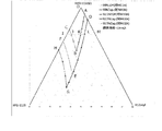
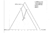
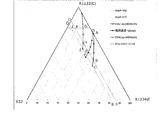
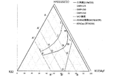
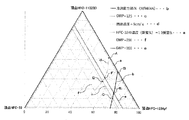
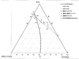
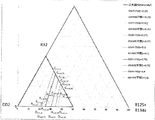
- FIG. 3 is a diagram showing points A to M and O and a line connecting them together in a three-component composition diagram in which the sum of HFO-1132 (E), HFO-1123 and R1234yf is 100% by mass.
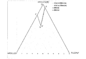
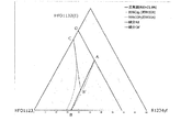
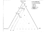
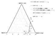
- FIG. 9 is a diagram showing points A to C, B ′ and O and lines connecting them together in a three-component composition diagram in which the sum of HFO-1132 (E), HFO-1123 and R1234yf is 100% by mass.
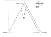
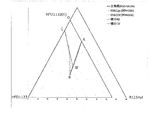
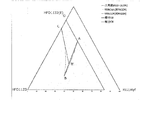
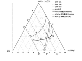
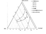
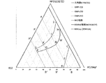
- FIG. Points A to C, B 'and O and lines connecting them are shown in a three-component composition diagram in which the sum of HFO-1132 (E), HFO-1123 and R1234yf is 83.5% by mass (R32 content ratio is 16.5% by mass).
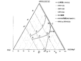
- FIG. Points A to C, B 'and O and lines connecting them are shown on a three-component composition diagram in which the sum of HFO-1132 (E), HFO-1123 and R1234yf is 80.8% by mass (R32 content ratio is 19.2% by mass).
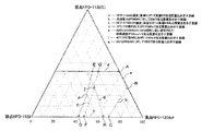
- FIG. 3 is a diagram showing points A to K and O to R and lines connecting them together in a three-component composition diagram in which the sum of HFO-1132 (E), R32 and R1234yf is 100% by mass.
- points A to D, A 'to D' and O and a line segment connecting them are shown. is there.
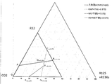
- FIG. 3 is a diagram showing points and lines defining the refrigerant of the present disclosure in a three-component composition diagram in which the sum of R32, HFO-1132 (E), and R1234yf is 100% by mass.
- the total of R32, HFO-1132 (E) and R1234yf is 99.4% by mass (CO 2 content ratio is 0.6% by mass) in the three-component composition diagram, showing points and lines defining the refrigerant of the present disclosure. is there.
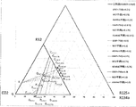
- R32, HFO-1132 (E) and R1234yf the sum of 98.8% by mass (CO 2 content ratio is 1.2% by mass) in the three-component composition diagram, showing the points and lines defining the refrigerant of the present disclosure is there.
- R32, HFO-1132 (E) and R1234yf the sum of 98.7% by mass (CO 2 content ratio is 1.3% by mass) in the three-component composition diagram, showing the points and lines defining the refrigerant of the present disclosure is there.
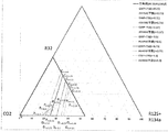
- R32, HFO-1132 (E) and R1234yf the sum of 97.5% by mass (CO 2 content ratio is 2.5% by mass) in the three-component composition diagram, showing the points and lines defining the refrigerant of the present disclosure.
- R32, HFO-1132 (E) and R1234yf have a total of 96% by mass (CO 2 content ratio is 4% by mass) in a three-component composition diagram showing points and lines defining the refrigerant of the present disclosure.
- R32, HFO-1132 (E) and R1234yf the sum of 94.5 mass% (CO 2 content ratio is 5.5 mass%) in the three-component composition diagram, the diagram showing the points and lines defining the refrigerant of the present disclosure is there.
- R32, HFO-1132 (E) and 3-component composition diagram which is a sum of R1234yf 93 wt% (CO 2 content of 7 wt%), in view illustrating the points and line segments define the refrigerant of the present disclosure is there.
- FIG. 7 is a diagram illustrating an area surrounded by a figure passing through six points of G.
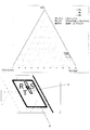
- FIG. 3 is a three-component composition diagram for describing the composition of a refrigerant 2D according to a first embodiment and a second embodiment of the present disclosure.
- the maximum composition of the refrigerant 2 ⁇ / b> D of the first embodiment is in the range of the rectangle indicated by X or on the line of the rectangle.
- the preferred composition of the refrigerant of the first embodiment is in the range of the rectangle indicated by Y or on the line segment of the rectangle.
- the composition of the refrigerant 2D of the second embodiment is within the range of a triangle surrounded by the line segments RS, ST, and TR or on the line segment. It is a three-component composition diagram for explaining the composition of the refrigerant of the third mode to the seventh mode of the refrigerant 2D.
- FIG. 3 is a triangular diagram showing ⁇ 1 and Q.
- FIG. 3 is a triangular diagram showing ⁇ 1 and Q.
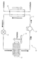
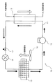
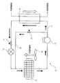
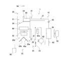
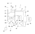
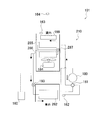
- FIG. 1 is a schematic configuration diagram of an automotive air conditioner according to a first embodiment of the present disclosure.
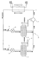
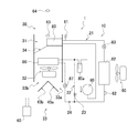
- the schematic block diagram of the air conditioner for motor vehicles which showed the circulation route of the refrigerant in heating mode.
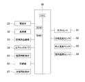
- FIG. 3 is a block diagram of a control device.
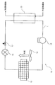
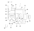
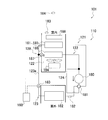
- the schematic block diagram of the automotive air conditioner which concerns on the modification of 1st Embodiment.
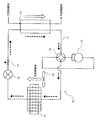
- the schematic block diagram of the air conditioner for motor vehicles which showed the circulation route of the refrigerant
- the schematic block diagram of the air conditioner for motor vehicles which showed the circulation route of the refrigerant in heating mode.
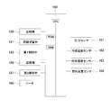
- FIG. 3 is a block diagram of a control device.
- the schematic block diagram of the automotive air conditioner which concerns on the modification of 2nd Embodiment.
- refrigerant refers to a compound provided with a refrigerant number (ASHRAE number) starting with R representing the type of refrigerant as defined by ISO817 (International Organization for Standardization). At least, even if a refrigerant number is not yet assigned, those having characteristics equivalent to those of the refrigerant are included.
- Refrigerants are broadly classified into “fluorocarbon compounds” and “non-fluorocarbon compounds” in terms of the structure of the compounds.
- the “fluorocarbon compound” includes chlorofluorocarbon (CFC), hydrochlorofluorocarbon (HCFC), and hydrofluorocarbon (HFC). Examples of the “non-fluorocarbon compound” include propane (R290), propylene (R1270), butane (R600), isobutane (R600a), carbon dioxide (R744), and ammonia (R717).
- composition containing a refrigerant includes (1) a refrigerant itself (including a mixture of refrigerants), and (2) further contains other components, and is mixed with at least a refrigerating machine oil to produce a refrigerating machine. At least a composition that can be used to obtain a working fluid for refrigerators, and (3) a working fluid for refrigerators containing refrigerator oil.
- the composition of (2) is referred to as a “refrigerant composition” to distinguish it from the refrigerant itself (including a mixture of refrigerants).
- the working fluid for a refrigerator of (3) is distinguished from the “refrigerant composition” and described as “a working fluid containing a refrigerator oil”.
- the second refrigerant is used only by changing a few parts (at least one of refrigerating machine oil, gasket, packing, expansion valve, dryer and other parts) and adjusting equipment as necessary Means that it can be operated under optimal conditions. That is, this type refers to operating the same device by “substituting” the refrigerant.
- this type of “alternative” “drop-in (drop ⁇ in) alternative”, “nearly drop-in ( There can be “nealy drop in replacement” and “retrofit”.
- refrigerator refers to any device that removes heat from an object or space to a temperature lower than the ambient air and maintains this low temperature.
- a refrigerator refers to a conversion device that obtains energy from the outside, performs work, and converts energy to transfer heat from a lower temperature to a higher temperature.
- the refrigerant is ⁇ non-combustible '' means that the refrigerant is the most flammable composition in the refrigerant allowable concentration in the U.S. ANSI / ASHRAE34-2013 standard, and the WCF (Worst case of formulation for flammability) composition is determined to be ⁇ Class 1. '' Means that
- the term “low-combustion” in the refrigerant means that the WCF composition is determined to be “class 2” in the US ANSI / ASHRAE34-2013 standard.
- the refrigerant is “ASHRAE non-combustible” when the WCF composition or the WCFF composition is ASTM No.E681-2009 (a standard test method for the flammable concentration limit of chemicals (steam and gas)). It refers to the case where non-flammability can be identified in the test based on the above, and it is classified as "Class 1 @ASHRAE non-combustible (WCF non-combustible)" or “Class 1 @ASHRAE non-combustible (WCFF non-combustible)", respectively.
- the WCFF composition (Worst case of fractionation for flammability: the most flammable mixed composition) is specified by performing a leak test during storage, transportation, and use based on ANSI / ASHRAE34-2013.
- the refrigerant is “slightly flammable” means that the WCF composition is determined to be “class 2L” in the US ANSI / ASHRAE34-2013 standard.
- the temperature glide may be paraphrased as an absolute value of a difference between a start temperature and an end temperature of a phase change process of a composition including a refrigerant of the present disclosure in a component of a heat cycle system. it can.
- the "vehicle air conditioner” is a type of refrigeration equipment used in vehicles such as gasoline vehicles, hybrid vehicles, electric vehicles, and hydrogen vehicles.
- In-vehicle air conditioning equipment means that a liquid refrigerant exchanges heat with an evaporator, the evaporated refrigerant gas is sucked by a compressor, and the adiabatic compressed refrigerant gas is cooled and liquefied by a condenser, and further an expansion valve
- a refrigerating device comprising a refrigeration cycle which is supplied to the evaporator again as a liquid refrigerant after being adiabatically expanded.
- the “centrifugal chiller” is a type of large chiller. With a centrifugal chiller, a liquid refrigerant is exchanged heat with an evaporator, the evaporated refrigerant gas is sucked by a centrifugal compressor, and the adiabatic compressed refrigerant gas is cooled and liquefied by a condenser, and further expanded. It refers to a refrigeration system consisting of a refrigeration cycle that is adiabatically expanded through a valve and then supplied to the evaporator again as a liquid refrigerant. Note that the “large refrigerator” refers to a large air conditioner for the purpose of air conditioning in a building unit.
- saturated pressure means the pressure of saturated steam.
- discharge temperature means the temperature of the mixed refrigerant at the discharge port of the compressor.
- evaporation pressure means a saturation pressure at an evaporation temperature
- critical temperature means a temperature at a critical point, and means a temperature at a boundary where a gas cannot be converted into a liquid unless the temperature is lower than the critical temperature.
- GWP means a value based on the value of the IPCC (Intergovernmental Panel On Change) fourth report.
- the description “mass ratio” is synonymous with the description “composition ratio”.
- refrigerant of the present disclosure can be used as the refrigerant.
- the refrigerant composition of the present disclosure includes at least the refrigerant of the present disclosure, and can be used for the same applications as the refrigerant of the present disclosure. Further, the refrigerant composition of the present disclosure can be used for obtaining a working fluid for a refrigerator by further mixing at least with a refrigerator oil.
- the refrigerant composition of the present disclosure further contains at least one other component in addition to the refrigerant of the present disclosure.
- the refrigerant composition of the present disclosure may contain at least one of the following other components as necessary.
- the refrigerant compositions of the present disclosure are preferably substantially free of refrigerating machine oil.
- the refrigerant composition of the present disclosure preferably has a refrigerating machine oil content of 0 to 1% by mass, more preferably 0 to 0.1% by mass, based on the entire refrigerant composition.
- the refrigerant composition of the present disclosure may contain a trace amount of water.
- the water content of the refrigerant composition is preferably 0.1% by mass or less based on the entire refrigerant. Since the refrigerant composition contains a trace amount of water, the intramolecular double bond of the unsaturated fluorocarbon compound that can be contained in the refrigerant is stabilized, and the oxidation of the unsaturated fluorocarbon compound is also less likely to occur. In addition, the stability of the refrigerant composition is improved.
- the tracer is added to the refrigerant composition of the present disclosure at a detectable concentration so that when the refrigerant composition of the present disclosure is diluted, contaminated, or has any other change, the change can be tracked. Is done.
- the refrigerant composition of the present disclosure may contain one kind alone or two or more kinds as tracers.
- the tracer is not particularly limited, and can be appropriately selected from commonly used tracers.
- hydrofluorocarbon, hydrochlorofluorocarbon, chlorofluorocarbon, hydrochlorocarbon, fluorocarbon, deuterated hydrocarbon, deuterated hydrofluorocarbon, perfluorocarbon, fluoroether, brominated compound, iodinated compound, alcohol, Aldehyde, ketone, nitrous oxide (N 2 O) and the like can be mentioned.
- hydrofluorocarbon, hydrochlorofluorocarbon, chlorofluorocarbon, hydrochlorocarbon, fluorocarbon and fluoroether are particularly preferred.
- FC-14 tetrafluoromethane, CF 4
- HCC-40 chloromethane, CH 3 Cl
- HFC-23 trifluoromethane, CHF 3
- HFC-41 fluoromethane, CH 3 Cl
- HFC-125 penentafluoroethane, CF 3 CHF 2
- HFC-134a (1,1,1,2-tetrafluoroethane, CF 3 CH 2 F)
- HFC-134 1,1,2,2-tetrafluoroethane, CHF 2
- HFC-143a 1,1,1-trifluoroethane, CF 3 CH 3
- HFC-143 (1,1,2-trifluoroethane, CHF 2 CH 2 F)
- HFC-152a 1,1-difluoroethane, CHF 2 CH 3
- HFC-152 (1,2-difluoroethane, CH 2 FCH 2 F)
- HFC-161 fluoroethanethanethane,
- the refrigerant composition of the present disclosure may include the tracer in total from about 10 parts per million by weight (ppm) to about 1000 ppm, based on the total refrigerant composition.
- the refrigerant compositions of the present disclosure may include tracers, preferably from about 30 ppm to about 500 ppm, more preferably from about 50 ppm to about 300 ppm, based on the total refrigerant composition.
- the refrigerant composition of the present disclosure may contain one type of ultraviolet fluorescent dye alone, or two or more types thereof.
- the ultraviolet fluorescent dye is not particularly limited, and can be appropriately selected from commonly used ultraviolet fluorescent dyes.
- the ultraviolet fluorescent dye examples include naphthalimide, coumarin, anthracene, phenanthrene, xanthene, thioxanthene, naphthoxanthene, and fluorescein, and derivatives thereof.
- the ultraviolet fluorescent dye one or both of naphthalimide and coumarin are particularly preferred.
- the refrigerant composition of the present disclosure may contain one type of stabilizer alone, or may contain two or more types of stabilizers.
- the stabilizer is not particularly limited, and can be appropriately selected from commonly used stabilizers.
- Examples of the stabilizer include nitro compounds, ethers and amines.
- nitro compound examples include aliphatic nitro compounds such as nitromethane and nitroethane, and aromatic nitro compounds such as nitrobenzene and nitrostyrene.
- ethers examples include 1,4-dioxane.
- amines examples include 2,2,3,3,3-pentafluoropropylamine, diphenylamine and the like.
- the content of the stabilizer is not particularly limited, and is usually preferably 0.01 to 5% by mass, and more preferably 0.05 to 2% by mass, based on the whole refrigerant.
- the refrigerant composition of the present disclosure may contain one kind alone or two or more kinds as a polymerization inhibitor.
- the polymerization inhibitor is not particularly limited, and can be appropriately selected from commonly used polymerization inhibitors.
- polymerization inhibitor examples include 4-methoxy-1-naphthol, hydroquinone, hydroquinone methyl ether, dimethyl-t-butylphenol, 2,6-di-tert-butyl-p-cresol, benzotriazole and the like.
- the content of the polymerization inhibitor is not particularly limited, and is usually preferably 0.01 to 5% by mass, and more preferably 0.05 to 2% by mass, based on the entire refrigerant.
- Refrigeration oil-containing working fluid contains at least the refrigerant or the refrigerant composition of the present disclosure and refrigeration oil, and is used as a working fluid in the refrigerator.
- the refrigerating machine oil-containing working fluid of the present disclosure is obtained by mixing a refrigerating machine oil used in a compressor of a refrigerator with a refrigerant or a refrigerant composition.
- the working fluid containing the refrigerating machine oil generally contains 10 to 50% by mass of the refrigerating machine oil.
- Refrigeration oil The composition of the present disclosure may contain one type alone or two or more types of refrigerator oil.
- the refrigerating machine oil is not particularly limited, and can be appropriately selected from commonly used refrigerating machine oils. At that time, if necessary, a refrigerating machine oil that is more excellent in the point of improving the compatibility with the mixture and the effect of improving the stability of the mixture and the like can be appropriately selected.
- the base oil of the refrigerator oil for example, at least one selected from the group consisting of polyalkylene glycol (PAG), polyol ester (POE) and polyvinyl ether (PVE) is preferable.
- PAG polyalkylene glycol
- POE polyol ester
- PVE polyvinyl ether
- Refrigeration oil may further contain additives in addition to the base oil.
- the additive may be at least one selected from the group consisting of an antioxidant, an extreme pressure agent, an acid scavenger, an oxygen scavenger, a copper deactivator, a rust inhibitor, an oil agent, and an antifoaming agent. .
- the refrigerating machine oil one having a kinematic viscosity at 40 ° C of 5 to 400 cSt is preferable in terms of lubrication.
- the refrigerating machine oil-containing working fluid of the present disclosure may further include at least one additive as necessary.
- the additives include the following compatibilizers.
- the refrigerating machine oil-containing working fluid of the present disclosure may contain one type alone or two or more types as a compatibilizer.
- the compatibilizer is not particularly limited, and can be appropriately selected from commonly used compatibilizers.
- compatibilizer examples include polyoxyalkylene glycol ether, amide, nitrile, ketone, chlorocarbon, ester, lactone, aryl ether, fluoroether and 1,1,1-trifluoroalkane.
- polyoxyalkylene glycol ether is particularly preferred.
- coolant 1E below is each independent,
- the alphabet which shows a point or a line segment, the number of an Example, and the number of a comparative example are all any. It is assumed that the refrigerant 1A, the refrigerant 1B, the refrigerant 1C, the refrigerant 1D, and the refrigerant 1E are independent from each other.
- Example 1 of the refrigerant 1A and Example 1 of the refrigerant 1B show examples of different embodiments.
- the refrigerant 1A of the present disclosure includes trans-1,2-difluoroethylene (HFO-1132 (E)), trifluoroethylene (HFO-1123) and 2,3,3,3-tetrafluoro-1-propene (R1234yf) It is a mixed refrigerant containing.
- ⁇ Refrigerant 1A of the present disclosure has the same refrigerating capacity and coefficient of performance as R410A, and has various characteristics desirable as an R410A substitute refrigerant, such that GWP is sufficiently small.
- the refrigerant 1A of the present disclosure is a composition containing HFO-1132 (E) and R1234yf, and if necessary, HFO-1123, and may further satisfy the following requirements.
- This refrigerant 1A also has the same refrigerating capacity and coefficient of performance as R410A, and has various characteristics desirable as an R410A substitute refrigerant, such that GWP is sufficiently small.
- HFO-1132 (E), HFO-1123 and R1234yf when the mass% based on the sum of these is x, y and z, respectively, HFO-1132 (E), the sum of HFO-1123 and R1234yf is 100.
- the coordinates (x, y, z) are Point D (87.6, 0.0, 12.4), Point G (18.2, 55.1, 26.7), Point H (56.7, 43.3, 0.0) and Point O (100.0, 0.0, 0.0)
- Point D 87.6, 0.0, 12.4
- Point G (18.2, 55.1, 26.7
- Point H (56.7, 43.3, 0.0)
- Point O 100.0, 0.0, 0.0
- the line segment DG is Coordinates (0.0047y 2 -1.5177y + 87.598, y, -0.0047y 2 + 0.5177y + 12.402)
- the line segment GH is Coordinates (-0.0134z 2 -1.0825z + 56.692, 0.0134z 2 + 0.0825z + 43.308, z)
- the line segments HO and OD are straight lines.
- the refrigerant 1A of the present disclosure has a refrigerating capacity ratio of 92.
- Refrigerant 1A of the present disclosure HFO-1132 (E), HFO-1123, and R1234yf, when the mass% based on the sum of these is x, y and z, respectively, HFO-1132 (E), HFO- In a three-component composition diagram in which the sum of 1123 and R1234yf is 100% by mass, the coordinates (x, y, z) are Point L (72.5, 10.2, 17.3), Point G (18.2, 55.1, 26.7), Point H (56.7, 43.3, 0.0) and Point I (72.5, 27.5, 0.0) Within the range of the figure surrounded by the line segments LG, GH, HI, and IL connecting the four points, respectively, or on the line segments LG, GH, and IL (excluding the points H and I), The line segment LG is Coordinates (0.0047y 2 -1.5177y + 87.598, y, -0.0047y 2 + 0.5177y + 12.402) Represented by The line segment GH is Coordinates (
- the refrigerant 1A of the present disclosure not only has a refrigerating capacity ratio based on R410A of 92.5% or more and a COP ratio based on R410A of 92.5% or more, but also has an ASHRAE standard. Indicates slight flammability (2L class).
- Refrigerant 1A of the present disclosure HFO-1132 (E), HFO-1123, and R1234yf, when the mass% based on the sum of these is x, y and z, respectively, HFO-1132 (E), HFO- In a three-component composition diagram in which the sum of 1123 and R1234yf is 100% by mass, the coordinates (x, y, z) are Point D (87.6, 0.0, 12.4), Point E (31.1, 42.9, 26.0), Point F (65.5, 34.5, 0.0) and Point O (100.0, 0.0, 0.0) Within the range of the figure surrounded by the line segments OD, DE, EF, and FO connecting the four points, respectively, or on the line segments OD, DE, and EF (excluding points O and F),
- the line segment DE is Coordinates (0.0047y 2 -1.5177y + 87.598, y, -0.0047y 2 + 0.5177y + 12.402) Represented by The line segment EF is Coordinate
- Refrigerant 1A of the present disclosure HFO-1132 (E), HFO-1123, and R1234yf, when the mass% based on the sum of these is x, y and z, respectively, HFO-1132 (E), HFO- In a three-component composition diagram in which the sum of 1123 and R1234yf is 100% by mass, the coordinates (x, y, z) are Point L (72.5, 10.2, 17.3), Point E (31.1, 42.9, 26.0), Point F (65.5, 34.5, 0.0) and Point I (72.5, 27.5, 0.0) Within the range of the graphic enclosed by the line segments LE, EF, FI, and IL connecting the four points respectively, or on the line segments LE, EF, and IL (excluding the points F and I), The line segment LE is Coordinates (0.0047y 2 -1.5177y + 87.598, y, -0.0047y 2 + 0.5177y + 12.402) Represented by The line segment EF is Coordinates (-0.0
- the refrigerant 1A of the present disclosure not only has a refrigerating capacity ratio based on R410A of 93.5% or more and a COP ratio based on R410A of 93.5% or more, but also has an ASHRAE standard. Indicates slight flammability (2L class).
- Refrigerant 1A of the present disclosure HFO-1132 (E), HFO-1123, and R1234yf, when the mass% based on the sum of these is x, y and z, respectively, HFO-1132 (E), HFO- In a three-component composition diagram in which the sum of 1123 and R1234yf is 100% by mass, the coordinates (x, y, z) are Point A (93.4, 0.0, 6.6), Point B (55.6, 26.6, 17.8), Point C (77.6, 22.4, 0.0) and Point O (100.0, 0.0, 0.0) Within the range of the figure surrounded by the line segments OA, AB, BC, and CO connecting the four points respectively, or on the line segments OA, AB, and BC (excluding the points O and C),
- the line segment AB is Coordinates (0.0052y 2 -1.5588y + 93.385, y, -0.0052y 2 + 0.5588y + 6.615) Represented by The line segment BC is
- Refrigerant 1A of the present disclosure HFO-1132 (E), HFO-1123, and R1234yf, when the mass% based on the sum of these is x, y and z, respectively, HFO-1132 (E), HFO- In a three-component composition diagram in which the sum of 1123 and R1234yf is 100% by mass, the coordinates (x, y, z) are Point K (72.5, 14.1, 13.4), Point B (55.6, 26.6, 17.8) and Point J (72.5, 23.2, 4.3) Are in the range of the graphic enclosed by the line segments KB, BJ and JK respectively connecting the three points or on the line segment, and the line segment KB is Coordinates (0.0052y 2 -1.5588y + 93.385, y, -0.0052y 2 + 0.5588y + 6.615) Represented by The line segment BJ is Coordinates (-0.0032z 2 -1.1791z + 77.593, 0.0032z 2 + 0.1791z + 2
- the refrigerant 1A of the present disclosure not only has a refrigerating capacity ratio based on R410A of 95% or more and a COP ratio based on R410A of 95% or more, but also has an ASHRAE standard. Indicates slight flammability (2L class).
- Refrigerant 1A of the present disclosure may further contain difluoromethane (R32) in addition to HFO-1132 (E), HFO-1123 and R1234yf, as long as the above-described characteristics and effects are not impaired.
- the content ratio of R32 to the entirety of the refrigerant 1A of the present disclosure is not particularly limited, and can be widely selected. For example, when the content ratio of R32 with respect to the entirety of the refrigerant 1A of the present disclosure is 21.8% by mass, the GWP of this mixed refrigerant is 150, so that the content ratio of R32 can be less than that.
- the content ratio of R32 to the entire refrigerant 1A of the present disclosure may be, for example, 5% by mass or more.
- the refrigerant 1A of the present disclosure further contains R32 in addition to HFO-1132 (E), HFO-1123 and R1234yf
- the refrigerant 1A is based on the sum of HFO-1132 (E), HFO-1123 and R1234yf and R32.
- FIGS. 1A In the three-component composition diagram (FIGS.
- the point B ′ is defined as a point B where the point where the refrigeration capacity ratio based on R410A is 95% and the COP ratio based on R410A is 95% in the three-component composition diagram is point B. Is the intersection of the approximate line connecting the points where the COP ratio is 95% and the line AB.
- the refrigerant 1A of the present disclosure has a refrigerating capacity ratio of 95% or more based on R410A and a COP ratio of 95% or more based on R410A.
- Refrigerant 1A of the present disclosure may contain, in addition to HFO-1132 (E), HFO-1123 and R1234yf and R32, other additional refrigerants within a range that does not impair the characteristics and effects described above. Good.
- the refrigerant 1A of the present disclosure preferably contains 99.5% by mass or more, and more preferably 99.75% by mass, of the total of HFO-1132 (E), HFO-1123, R1234yf, and R32 based on the entire refrigerant 1A. Is more preferable, and more preferably 99.9% by mass or more.
- the refrigerant 1A of the present disclosure may contain the total of HFO-1132 (E), HFO-1123, and R1234yf in an amount of 99.5% by mass or more, or 99.75% by mass or more based on the entire refrigerant 1A. And may further contain 99.9% by mass or more.
- the refrigerant 1A of the present disclosure may include HFO-1132 (E), the sum of HFO-1123, R1234yf, and R32, which may contain 99.5% by mass or more based on the entire refrigerant 1A, and may contain 99.75% by mass or more. And may further contain 99.9% by mass or more.
- HFO-1132 E
- the sum of HFO-1123, R1234yf, and R32 which may contain 99.5% by mass or more based on the entire refrigerant 1A, and may contain 99.75% by mass or more. And may further contain 99.9% by mass or more.
- the additional refrigerant is not particularly limited and can be widely selected.
- the mixed refrigerant may contain one kind alone or two or more kinds as additional refrigerants.
- the refrigerant 1A of the present disclosure is suitable for use as a substitute refrigerant for R410A.
- a mixed refrigerant was prepared by mixing HFO-1132 (E), HFO-1123, and R1234yf at the mass% shown in Tables 1 to 5, based on the sum of these.
- HFO-1132 (E), HFO-1123 and R1234yf when the mass% based on the sum of these is x, y and z, respectively, HFO-1132 (E), HFO-1123 and
- the coordinates (x, y, z) are Point D (87.6, 0.0, 12.4), Point G (18.2, 55.1, 26.7), Point H (56.7, 43.3, 0.0) and Point O (100.0, 0.0, 0.0) Is within the range of the figure (FIG. 1B) surrounded by the line segments OD, DG, GH, and HO connecting the four points respectively (except for the points O and H).
- the refrigeration capacity ratio based on R410A is 92.5% or more
- the COP ratio based on R410A is 92.5% or more.
- the coordinates (x, y, z) are Point D (87.6, 0.0, 12.4), Point E (31.1, 42.9, 26.0), Point F (65.5, 34.5, 0.0) and Point O (100.0, 0.0, 0.0) Is within the range of the figure (FIG. 1B) surrounded by the line segments OD, DE, EF and FO respectively connecting the four points (excluding points O and F) It can be seen that the refrigeration capacity ratio based on R410A is 93.5% or more, and the COP ratio based on R410A is 93.5% or more.
- the coordinates (x, y, z) are Point A (93.4, 0.0, 6.6), Point B (55.6, 26.6, 17.8), Point C (77.6, 22.4, 0.0) and Point O (100.0, 0.0, 0.0) Within the range of the figure (Fig. 1B) surrounded by the line segments OA, AB, BC, and CO connecting the four points respectively (except for the points O and C) It can be seen that the refrigerating capacity ratio based on R410A is 95% or more, and the COP ratio based on R410A is 95% or more.
- R1234yf contributes to the suppression of deterioration such as flammability and polymerization, and it is preferable that R1234yf is contained.
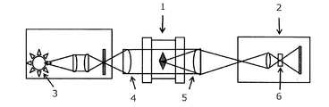
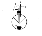
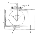
- the burning rate test was performed as follows using the apparatus shown in FIG. 1A. First, the mixed refrigerant used was 99.5% or more pure and degassed by repeating the cycle of freezing, pumping and thawing until no traces of air were visible on the vacuum gauge. The burning rate was measured by the closed method. The initial temperature was ambient temperature. Ignition was performed by creating an electrical spark between the electrodes at the center of the sample cell. The duration of the discharge was 1.0-9.9 ms and the ignition energy was typically about 0.1-1.0 J. The spread of the flame was visualized using Schlieren photographs.
- a cylindrical container (inner diameter: 155 mm, length: 198 mm) provided with two acrylic windows through which light was used was used was used as a sample cell, and a xenon lamp was used as a light source. Flame schlieren images were recorded with a high-speed digital video camera at a framing speed of 600 fps and stored on a PC.
- a mixed refrigerant was prepared by mixing HFO-1132 (E), HFO-1123, R1234yf, and R32 at the mass% shown in Tables 6 to 12 based on the sum of these.
- HFO-1132 (E), HFO-1123 and R1234yf and R32 when the mass% based on the sum of these as x, y and z and a, respectively, HFO-1132 (E),
- HFO-1132 (E) In the three-component composition diagram (FIGS.
- 1C to 1I show that the R32 content ratio a (mass%) is 0 mass%, 5 mass%, 10 mass%, 14.3 mass%, 16.5 mass%, 19.2 mass%, and 21.8 mass%, respectively. Represents the composition in the case of.
- the point B ′ is defined as a point B where the point at which the refrigerating capacity ratio based on R410A is 95% and the COP ratio based on R410A is 95% in the three-component composition diagram is point B. Is an intersection of an approximate straight line connecting three points including the point C at which the COP ratio becomes 95%, and the straight line AB.
- Points A, B 'and C were determined by approximate calculation as follows.
- Point A is a point where the HFO-1123 content ratio is 0% by mass and the refrigerating capacity ratio based on R410A is 95%.
- point A three points were determined for each of the following three ranges by calculation, and their approximate expressions were determined.
- Point C is a point where the R1234yf content ratio is 0% by mass and the COP ratio based on R410A is 95%. Regarding the point C, three points were obtained by calculation in each of the following three ranges, and these approximate expressions were obtained.
- the refrigerant 1B includes: The total of HFO-1132 (E) and HFO-1123 is not less than 99.5% by mass with respect to the entire refrigerant 1B, and This is a mixed refrigerant containing HFO-1132 (E) in an amount of 62.5% by mass to 72.5% by mass with respect to the entire refrigerant 1B.
- the refrigerant 1B of the present disclosure (1) has a coefficient of performance equivalent to R410A, (2) has a refrigerating capacity equivalent to R410A, (3) GWP is sufficiently small, and (4) ASHRAE standard And it is slightly flammable (2L class).
- the refrigerant 1B of the present disclosure is particularly preferable if it is a mixed refrigerant containing 72.5% by mass or less of HFO-1132 (E) because it becomes slightly flammable (2L class) according to ASHRAE standards.
- the refrigerant 1B of the present disclosure is more preferably a mixed refrigerant containing 62.5% by mass or more of HFO-1132 (E).
- the refrigerant 1B of the present disclosure has a more excellent coefficient of performance ratio based on R410A, and further suppresses the polymerization reaction of HFO-1132 (E) and / or HFO-1123, thereby improving stability. It will be excellent.
- Refrigerant 1B of the present disclosure may further contain other additional refrigerants in addition to HFO-1132 (E) and HFO-1123 as long as the above-described characteristics and effects are not impaired.
- the refrigerant 1B of the present disclosure more preferably contains the sum of HFO-1132 (E) and HFO-1123 in an amount of at least 99.75% by mass, more preferably at least 99.9% by mass, based on the entire refrigerant 1B. .
- the additional refrigerant is not particularly limited and can be widely selected.
- the mixed refrigerant may contain one kind alone or two or more kinds as additional refrigerants.
- the refrigerant 1B of the present disclosure is suitable for use as an alternative refrigerant to HFC refrigerants such as R410A, R407C and R404A, and HCFC refrigerants such as R22.
- a mixed refrigerant was prepared by mixing HFO-1132 (E) and HFO-1123 at the mass% (mass%) shown in Tables 16 and 17, respectively, based on the sum of these.
- the refrigerating capacity of the composition containing R410A and the mixture of HFO-1132 (E) and HFO-1123 was determined using the National Institute of Science and Technology (NIST) Reference Fluid Thermodynamic and Transport Properties Database (Refprop 9.0) under the following conditions. The theoretical calculation of the refrigeration cycle of the mixed refrigerant was carried out in the above. Evaporation temperature 5 °C Condensing temperature 45 ° C Superheat temperature 1K Supercooling temperature 5K Compressor efficiency 70%
- COP (refrigeration capacity or heating capacity) / power consumption
- the flammability measured the burning rate according to ANSI / ASHRAE34-2013 standard. Those with a burning speed of 10 cm / s or less were classified as "2L class (slightly flammable)".
- the burning rate test was performed as follows using the apparatus shown in FIG. 1A.
- the mixed refrigerant used was 99.5% or more pure and degassed by repeating the cycle of freezing, pumping and thawing until no traces of air were visible on the vacuum gauge.
- the burning rate was measured by the closed method.
- the initial temperature was ambient temperature.
- Ignition was performed by creating an electrical spark between the electrodes at the center of the sample cell.
- the duration of the discharge was 1.0-9.9 ms and the ignition energy was typically about 0.1-1.0 J.
- the spread of the flame was visualized using Schlieren photographs.
- a cylindrical container (inner diameter: 155 mm, length: 198 mm) provided with two acrylic windows through which light was used was used was used as a sample cell, and a xenon lamp was used as a light source. Flame schlieren images were recorded with a high-speed digital video camera at a framing speed of 600 fps and stored on a PC.
- Refrigerant 1C of the present disclosure is a mixed refrigerant containing HFO-1132 (E), R32, and 2,3,3,3-tetrafluoro-1-propene (R1234yf).
- ⁇ Refrigerant 1C of the present disclosure has the same cooling capacity as R410A, has sufficiently small GWP, and is slightly flammable (2L class) according to ASHRAE standards.
- Refrigerant 1C of the present disclosure is HFO-1132 (E), R32 and R1234yf, when the mass% based on the sum of these is x, y and z, respectively, HFO-1132 (E), R32 and R1234yf
- the coordinates (x, y, z) are Point A (71.1, 0.0, 28.9), Point C (36.5, 18.2, 45.3), Point F (47.6, 18.3, 34.1) and Point D (72.0, 0.0, 28.0) are in the range of the figure surrounded by the line segments AC, CF, FD, and DA respectively or on the line segment
- the line segment AC is Coordinates (0.0181y 2 -2.2288y + 71.096, y, -0.0181y 2 + 1.2288y + 28.904)
- the line segment FD is Coordinates (0.02y 2 -1.7y + 72, y, -0.02y 2 +
- the refrigerant 1C of the present disclosure has a refrigerating capacity ratio based on R410A of 85% or more, a GWP of 125 or less, and becomes slightly flammable (2L class) according to ASHRAE standards.
- Refrigerant 1C of the present disclosure is HFO-1132 (E), R32 and R1234yf, when the mass% based on the sum of these is x, y and z, respectively, HFO-1132 (E), R32 and R1234yf
- the coordinates (x, y, z) are Point A (71.1, 0.0, 28.9), Point B (42.6, 14.5, 42.9), Point E (51.4, 14.6, 34.0) and Point D (72.0, 0.0, 28.0)
- the line segment AB is Coordinates (0.0181y 2 -2.2288y + 71.096, y, -0.0181y 2 + 1.2288y + 28.904)
- the line segment ED is Coordinates (0.02y 2 -1.7y + 72, y, -0.02y
- the refrigerant 1C of the present disclosure has a refrigerating capacity ratio based on R410A of 85% or more, a GWP of 100 or less, and becomes slightly flammable (2L class) according to ASHRAE standards.
- Refrigerant 1C of the present disclosure is HFO-1132 (E), R32 and R1234yf, when the mass% based on the sum of these is x, y and z, respectively, HFO-1132 (E), R32 and R1234yf
- the coordinates (x, y, z) are Point G (77.5, 6.9, 15.6), Point I (55.1, 18.3, 26.6) and Point J (77.5.
- the refrigerant 1C of the present disclosure has a refrigerating capacity ratio of 95% or more based on R410A, a GWP of 100 or less, and is unlikely to undergo changes such as polymerization and decomposition, and has excellent stability. I have.
- Refrigerant 1C of the present disclosure is HFO-1132 (E), R32 and R1234yf, when the mass% based on the sum of these is x, y and z, respectively, HFO-1132 (E), R32 and R1234yf
- the coordinates (x, y, z) are Point G (77.5, 6.9, 15.6), Point H (61.8, 14.6, 23.6) and Point K (77.5, 14.6, 7.9)
- the line segments GH, HK and KG connecting the three points of the above or on the line segment
- the line segment GH is Coordinates (0.02y 2 -2.4583y + 93.396, y, -0.02y 2 + 1.4583y + 6.604)
- the line segments HK and KG are straight lines.
- the refrigerant 1C of the present disclosure has a refrigerating capacity ratio of 95% or more based on R410A, a GWP of 100 or less, and is unlikely to undergo changes such as polymerization and decomposition, and has excellent stability. I have.
- Refrigerant 1C of the present disclosure may further contain other additional refrigerants in addition to HFO-1132 (E), R32, and R1234yf as long as the above-described characteristics and effects are not impaired.
- the refrigerant 1C of the present disclosure preferably contains HFO-1132 (E), the sum of R32 and R1234yf, at least 99.5% by mass, more preferably at least 99.75% by mass, based on the entire refrigerant 1C, More preferably, it contains 99.9% by mass or more.
- the additional refrigerant is not particularly limited and can be widely selected.
- the mixed refrigerant may contain one kind alone or two or more kinds as additional refrigerants.
- the refrigerant 1C of the present disclosure is suitable for use as an alternative refrigerant to R410A.
- the burning rate test was performed as follows using the apparatus shown in FIG. 1A. First, the mixed refrigerant used was 99.5% or more pure and degassed by repeating the cycle of freezing, pumping and thawing until no traces of air were visible on the vacuum gauge. The burning rate was measured by the closed method. The initial temperature was ambient temperature. Ignition was performed by creating an electrical spark between the electrodes at the center of the sample cell. The duration of the discharge was 1.0-9.9 ms and the ignition energy was typically about 0.1-1.0 J. The spread of the flame was visualized using Schlieren photographs.
- a cylindrical container (inner diameter: 155 mm, length: 198 mm) provided with two acrylic windows through which light was used was used was used as a sample cell, and a xenon lamp was used as a light source. Flame schlieren images were recorded with a high-speed digital video camera at a framing speed of 600 fps and stored on a PC.
- a refrigerant mixture was prepared by mixing HFO-1132 (E), R32 and R1234yf at the mass% shown in Tables 19 to 23 based on the sum of these. For each of the mixed refrigerants shown in Tables 19 to 23, a coefficient of performance (COP) ratio and a refrigeration capacity ratio based on R410 were determined. The calculation conditions were as follows. Evaporation temperature: 5 ° C Condensing temperature: 45 ° C Superheat degree: 1K Supercooling degree: 5K E comp (compression work): 0.7kWh
- the refrigerating capacity ratio based on R410A becomes 85% or more, It can be seen that the GWP is 125 or less and that it is slightly flammable (2L class) according to ASHRAE standards.
- the coordinates (x, y, z) are Point A (71.1, 0.0, 28.9), Point B (42.6, 14.5, 42.9), Point E (51.4, 14.6, 34.0) and Point D (72.0, 0.0, 28.0)
- the refrigerating capacity ratio based on R410A becomes 85% or more, It can be seen that GWP is less than 100 and that it is slightly flammable (2L class) according to ASHRAE standards.
- the coordinates (x, y, z) are Point G (77.5, 6.9, 15.6), Point I (55.1, 18.3, 26.6) and Point J (77.5. 18.4, 4.1)
- the refrigeration capacity ratio based on R410A is 95% or more
- the GWP is 125 It turns out that it is less, and it is hard to cause change, such as polymerization and decomposition, and it turns out that it is excellent in stability.
- the coordinates (x, y, z) are Point G (77.5, 6.9, 15.6), Point H (61.8, 14.6, 23.6) and Point K (77.5, 14.6, 7.9)
- the refrigeration capacity ratio based on R410A is 95% or more, and the GWP is 100% or less within the range of the figure (FIG. 1J) surrounded by the line segments GH, HK, and KG connecting the three points, respectively. It turns out that it is less, and it is hard to cause change, such as polymerization and decomposition, and it turns out that it is excellent in stability.
- the refrigerant 1D of the present disclosure is a mixed refrigerant including HFO-1132 (E), HFO-1123, and R32.
- the refrigerant 1D of the present disclosure has various characteristics desirable as an R410A substitute refrigerant, having a coefficient of performance equivalent to that of R410A and having a sufficiently small GWP.
- Refrigerant 1D of the present disclosure HFO-1132 (E), HFO-1123 and R32, when the mass% based on the sum of these is x, y and z, respectively, HFO-1132 (E), HFO-
- the coordinates (x, y, z) are Point O (100.0, 0.0, 0.0), Point C '(56.7, 43.3, 0.0), Point D '(52.2, 38.3, 9.5), Point E '(41.8, 39.8, 18.4) and Point A' (81.6, 0.0, 18.4) Lines OC ', C'D', D'E ', E'A' and A'O, which connect the five points respectively, or within the range of the figure surrounded by the lines C'D ', D'E' and On E'A '(except points C' and A '), The line segment C'D 'is Coordinates (-0.0297z 2 -
- Refrigerant 1D of the present disclosure HFO-1132 (E), HFO-1123 and R32, when the mass% based on the sum of these is x, y and z, respectively, HFO-1132 (E), HFO- In a three-component composition diagram in which the sum of 1123 and R32 is 100% by mass, the coordinates (x, y, z) are Point O (100.0, 0.0, 0.0), Point C (77.7, 22.3, 0.0), Point D (76.3, 14.2, 9.5), Point E (72.2, 9.4, 18.4) and Point A '(81.6, 0.0, 18.4) Are within the range of the figure enclosed by the line segments OC, CD, DE, EA 'and A'O connecting the five points, respectively, or on the line segments CD, DE and EA' (excluding points C and A ' ), The line CDE is Coordinates (-0.017z 2 + 0.0148z + 77.684, 0.017z 2 + 0.9852z + 22.316, z) And it
- Refrigerant 1D of the present disclosure HFO-1132 (E), HFO-1123 and R32, when the mass% based on the sum of these is x, y and z, respectively, HFO-1132 (E), HFO- In a three-component composition diagram in which the sum of 1123 and R32 is 100% by mass, the coordinates (x, y, z) are Point O (100.0, 0.0, 0.0), Point C '(56.7, 43.3, 0.0), Point D '(52.2, 38.3, 9.5) and Point A (90.5, 0.0, 9.5) Are within the range of the figure surrounded by the line segments OC ', C'D', D'A and AO connecting the five points respectively, or on the line segments C'D 'and D'A (where A)), The line segment C'D 'is Coordinates (-0.0297z 2 -0.1915z + 56.7, 0.0297z 2 + 1.1915z + 43.3, z) It is preferable that the line
- Refrigerant 1D of the present disclosure HFO-1132 (E), HFO-1123 and R32, when the mass% based on the sum of these is x, y and z, respectively, HFO-1132 (E), HFO- In a three-component composition diagram in which the sum of 1123 and R32 is 100% by mass, the coordinates (x, y, z) are Point O (100.0, 0.0, 0.0), Point C (77.7, 22.3, 0.0), Point D (76.3, 14.2, 9.5), Point A (90.5, 0.0, 9.5) Within the range of the figure surrounded by the line segments OC, CD, DA and AO connecting the five points respectively, or on the line segments CD and DA (excluding points C and A), The line segment CD is Coordinates (-0.017z 2 + 0.0148z + 77.684, 0.017z 2 + 0.9852z + 22.316, z) And it is preferable that the line segments OC, DA and AO are straight lines. When the above requirements are
- Refrigerant 1D of the present disclosure may further contain other additional refrigerants in addition to HFO-1132 (E), HFO-1123 and R32 as long as the above-described characteristics and effects are not impaired.
- the refrigerant 1D of the present disclosure preferably includes HFO-1132 (E), a total of HFO-1123 and R32, of 99.5% by mass or more based on the entire refrigerant 1D, and more preferably 99.75% by mass or more. More preferably, the content is 99.9% by mass or more.
- the additional refrigerant is not particularly limited and can be widely selected.
- the mixed refrigerant may contain one kind alone or two or more kinds as additional refrigerants.
- the refrigerant 1D of the present disclosure is suitable for use as an alternative refrigerant to R410A.
- a mixed refrigerant was prepared by mixing HFO-1132 (E), HFO-1123 and R32 at the mass% shown in Tables 24-26 based on the sum of these.
- the COP ratio based on R410 and the refrigeration capacity [Refrigeration (Capacity (sometimes expressed as Cooling Capacity or Capacity)] ratio were determined.
- the calculation conditions were as follows.
- HFO-1132 (E), HFO-1123 and R32 when the mass% based on the sum of them is x, y and z, respectively, HFO-1132 (E), HFO-1123 and
- the coordinates (x, y, z) are Point O (100.0, 0.0, 0.0), Point C '(56.7, 43.3, 0.0), Point D '(52.2, 38.3, 9.5), Point E '(41.8, 39.8, 18.4) and Point A' (81.6, 0.0, 18.4) Within the range of a figure (FIG.
- the coordinates (x, y, z) are Point O (100.0, 0.0, 0.0), Point C (77.7, 22.3, 0.0), Point D (76.3, 14.2, 9.5), Point E (72.2, 9.4, 18.4) and Point A '(81.6, 0.0, 18.4) Is within the range of the figure (FIG. 1K) surrounded by the line segments OC, CD, DE, EA 'and A'O connecting the five points (the point C And A '), the COP ratio based on R410A is 95% or more, and the GWP is 125 or less.
- the coordinates (x, y, z) are Point O (100.0, 0.0, 0.0), Point C '(56.7, 43.3, 0.0), Point D '(52.2, 38.3, 9.5) and Point A (90.5, 0.0, 9.5) Is within the range of the figure (FIG. 1K) surrounded by the line segments OC ', C'D', D'A, and AO connecting the five points, respectively, or on the line segments C'D 'and D'A (however, , Except for the points C ′ and A), the COP ratio based on R410A is 92.5% or more, and the GWP is 65 or less.
- the coordinates (x, y, z) are Point O (100.0, 0.0, 0.0), Point C (77.7, 22.3, 0.0), Point D (76.3, 14.2, 9.5), Point A (90.5, 0.0, 9.5)
- Point O 100.0, 0.0, 0.0
- Point C 77.7, 22.3, 0.0
- Point D 7.6.3, 14.2, 9.5
- Point A 90.5, 0.0, 9.5
- R410A It can be seen that the reference COP ratio is 95% or more and the GWP is 65 or less.
- Refrigerant 1E of the present disclosure is a mixed refrigerant containing CO 2 and R32, HFO-1132 (E) and R1234yf.
- ⁇ Refrigerant 1E of the present disclosure has the same cooling capacity as R410A, has sufficiently small GWP, and is slightly flammable.
- Refrigerant 1E of the present disclosure CO 2, and R32, the HFO-1132 (E) and R1234yf, w mass% to these criteria the sum respectively, and x, when the y and z, R32, HFO-
- ⁇ Refrigerant 1E of the present disclosure has a refrigerating capacity ratio of 80% or more based on R410A, a GWP of 350 or less, and WCF slightly burned.
- Refrigerant 1E of the present disclosure CO 2, and R32, the HFO-1132 (E) and R1234yf, w mass% to these criteria the sum respectively, and x, when the y and z, R32, HFO- In a three-component composition diagram in which the sum of 1132 (E) and R1234yf is (100-w) mass%, coordinates (x, y, z) are When 0 ⁇ w ⁇ 1.2, Point I (0.0, 72.0, 28.0-w) Point J (18.3, 48.5, 33.2-w) Point K (36.8, 35.6, 27.6-w) Point F (-0.0833w + 36.717, -4.0833w + 5.1833, 3.1666w + 58.0997) Point C (0.0, -4.9167w + 58.317, 3.9167w + 41.683) The curve IJ and the curve JK connecting the five points respectively, and within the range of the graphic surrounded by the straight line KF, the straight line FC and the
- Refrigerant 1E of the present disclosure CO 2, and R32, the HFO-1132 (E) and R1234yf, w mass% to these criteria the sum respectively, and x, when the y and z, R32, HFO- In a three-component composition diagram in which the sum of 1132 (E) and R1234yf is (100-w) mass%, coordinates (x, y, z) are When 0 ⁇ w ⁇ 1.2, Point I (0.0, 72.0, 28.0-w) Point J (18.3, 48.5, 33.2-w) Point E (18.2, -1.1111w 2 -3.1667w + 31.9, 1.1111w 2 + 2.1667w + 49.9) Point C (0.0, -4.9167w + 58.317, 3.9167w + 41.683) Are within the range of the figure surrounded by the curves IJ and JK, and the straight line KF, the straight line FC and the straight line CI, or on the line segment (excluding points on the straight line
- Refrigerant 1E of the present disclosure CO 2, and R32, the HFO-1132 (E) and R1234yf, w mass% to these criteria the sum respectively, and x, when the y and z, R32, HFO- In a three-component composition diagram in which the sum of 1132 (E) and R1234yf is (100-w) mass%, coordinates (x, y, z) are When 0 ⁇ w ⁇ 0.6, Point G (-5.8333w 2 -3.1667w + 22.2, 7.0833w 2 + 1.4167w + 26.2, -1.25w 2 + 0.75w + 51.6) Point O (36.8, 0.8333w 2 + 1.8333w + 22.6, -0.8333w 2 -2.8333w + 40.6) Point P (51.7, 1.1111w 2 +20.5, -1.1111w 2 -w + 27.8) Point B '' (-1.5278w 2 + 2.75w + 50.5, 0.0, 1.5278w
- Point G (-5.8333w 2 -3.1667w + 22.2, 7.0833w 2 + 1.4167w + 26.2, -1.25w 2 + 0.75w + 51.6)
- Point N (18.2, 0.2778w2 + 3w + 27.7, -0.2778w2-4w + 54.1)
- Point O (36.8, 0.8333w 2 + 1.8333w + 22.6, -0.8333w 2 -2.8333w + 40.6)
- Point P (51.7, 1.1111w 2 +20.5, -1.1111w 2 -w + 27.8)
- Point B '' (-1.5278w 2 + 2.75w + 50.5, 0.0, 1.5278w 2 -3.75w + 49.5)
- Point D (-2.9167w + 40.317, 0.0, 1.9167w + 59.683)
- the curve GN, the curve NO, and the curve OP connecting the six points respectively, and within the range of the graphic surrounded by the straight lines PB ′′, B
- Curve MW is Coordinates (x, (0.0043w 2 -0.0359w + 0.1509) x 2 + (-0.0493w 2 + 0.4669w-3.6193) x-0.3004w 2 + 2.419w + 55.53, 100-wxy) Represented by Curve WN is Coordinates (x, (0.0055w 2 -0.0326w + 0.0665) x 2 + (-0.1571w 2 + 0.8981w-2.6274) x + 0.6555w 2 -2.2153w + 54.044, 100-wxy) Represented by Curve NO is Coordinates (x, (-0.00062w 2 + 0.0036w + 0.0037) x 2 + (0.0375w 2 -0.239w-0.4977) x-0.8575w 2 + 6.4941w + 36.078, 100-wxy) Represented by The curve OP is Coordinates (x, (0.0043w 2 -0.0359w + 0.1509) x 2 +
- Refrigerant 1E of the present disclosure CO 2, and R32, the HFO-1132 (E) and R1234yf, w mass% to these criteria the sum respectively, and x, when the y and z, R32, HFO- In a three-component composition diagram in which the sum of 1132 (E) and R1234yf is (100-a) mass%, coordinates (x, y, z) are When 0 ⁇ w ⁇ 0.6, Point G (-5.8333w 2 -3.1667w + 22.2, 7.0833w 2 -1.4167w + 26.2, -1.25w 2 + 3.5834w + 51.6) Point O (36.8, 0.8333w 2 + 1.8333w + 22.6, -0.8333w 2 -2.8333w + 40.6) Point F (-0.0833w + 36.717, -4.0833w + 5.1833, 3.1666w + 58.0997) Are within the range of the graphic surrounded by the straight line OF and the straight line FG or
- Curve MW is Coordinates (x, (0.0043w 2 -0.0359w + 0.1509) x 2 + (-0.0493w 2 + 0.4669w-3.6193) x-0.3004w 2 + 2.419w + 55.53, 100-wxy) Represented by Curve WN is Coordinates (x, (0.0055w 2 -0.0326w + 0.0665) x 2 + (-0.1571w 2 + 0.8981w-2.6274) x + 0.6555w 2 -2.2153w + 54.044, 100-wxy) Represented by Curve NO is Coordinates (x, (-0.00062w 2 + 0.0036w + 0.0037) x 2 + (0.0375w 2 -0.239w-0.4977) x-0.8575w 2 + 6.4941w + 36.078, 100-wxy) Represented by 1.3 ⁇ w ⁇ 4.0, Point M (0.0, -0.3004w 2 + 2.419w +
- Refrigerant 1E of the present disclosure CO 2, and R32, the HFO-1132 (E) and R1234yf, w mass% to these criteria the sum respectively, and x, when the y and z, R32, HFO- In a three-component composition diagram in which the sum of 1132 (E) and R1234yf is (100-a) mass%, coordinates (x, y, z) are When 1.2 ⁇ w ⁇ 4.0, Point M (0.0, -0.3004w 2 + 2.419w + 55.53, 0.3004w 2 -3.419w + 44.47) Point W (10.0, -0.3645w 2 + 3.5024w + 34.422, 0.3645w 2 -4.5024w + 55.578) Point N (18.2, -0.3773w 2 + 3.319w + 28.26, 0.3773w 2 -4.319w + 53.54) Point E (-0.0365w + 18.26, 0.0623w 2 -4.5381w + 31.8
- Refrigerant 1E of the present disclosure may contain, in addition to CO 2 , and R32, HFO-1132 (E) and R1234yf, other additional refrigerants within a range that does not impair the characteristics and effects described above. Good.
- the refrigerant 1E of the present disclosure preferably contains 99.5% by mass or more, more preferably 99.75% by mass or more of CO 2 , and the total of R32, HFO-1132 (E) and R1234yf based on the entire refrigerant. More preferably, the content is more preferably 99.9% by mass or more.
- the additional refrigerant is not particularly limited and can be widely selected.
- the mixed refrigerant may contain one kind alone or two or more kinds as additional refrigerants.
- the refrigerant 1E of the present disclosure can be preferably used as a working fluid in a refrigerator.
- compositions of the present disclosure are suitable for use as an alternative refrigerant to R410A.
- the combustion rate of CO 2 and the refrigerant mixture of R32, HFO-1132 (E) and R1234yf was measured in accordance with the ANSI / ASHRAE34-2013 standard. While changing the concentration of CO 2 , a composition having a burning rate of 10 cm / s was found. The compositions found are shown in Tables 27-29.
- the burning rate test was performed as follows using the apparatus shown in FIG. 1A. First, the mixed refrigerant used was 99.5% or more pure and degassed by repeating the cycle of freezing, pumping and thawing until no traces of air were visible on the vacuum gauge. The burning rate was measured by the closed method. The initial temperature was ambient temperature. Ignition was performed by creating an electrical spark between the electrodes at the center of the sample cell. The duration of the discharge was 1.0-9.9 ms and the ignition energy was typically about 0.1-1.0 J. The spread of the flame was visualized using Schlieren photographs.
- a cylindrical container (inner diameter: 155 mm, length: 198 mm) provided with two acrylic windows through which light was used was used was used as a sample cell, and a xenon lamp was used as a light source. Flame schlieren images were recorded with a high-speed digital video camera at a framing speed of 600 fps and stored on a PC.
- the WCFF concentration was obtained by performing a leak simulation using NIST Standard Reference Data Base Refleak Version 4.0 with the WCF concentration as the initial concentration.
- the refrigeration capacity of a composition containing a mixture with R410A and HFO-1132 (E), HFO-1123, R1234yf was determined using the National Institute of Science and Technology (NIST) Reference Fluid Thermodynamic and Transport Properties Database (Refprop 9.0), It was determined by performing a refrigeration cycle theoretical calculation of a mixed refrigerant under the following conditions.
- Tables 30 to 37 show the cases where the CO 2 concentration is 0% by mass, 0.6% by mass, 1.2% by mass, 1.3% by mass, 2.5% by mass, 4% by mass, 5.5% by mass, and 7% by mass, respectively. .
- the coordinates of the points on the curve MW and the curve WM were determined by obtaining an approximate expression based on each point described in the above table. Specifically in Table 53 (0 wt% ⁇ When the CO 2 concentration ⁇ 1.2% by weight), Table 54 (1.2 wt% ⁇ CO 2 when a concentration ⁇ 4.0% by weight), Table 55 (4.0 wt% ⁇ CO 2 concentration ⁇ 7.0% by mass).
- the coordinates of the points on the curve NO and the curve OP were determined by obtaining an approximate expression based on each point described in the above table. Specifically in Table 56 (0 wt% ⁇ When the CO 2 concentration ⁇ 1.2% by weight), Table 57 (1.2 wt% ⁇ When the CO 2 concentration ⁇ 4.0 wt%) and Table 58 (4.0 wt% ⁇ CO 2 concentration ⁇ 7.0% by mass).
- coolant 2E is independent, respectively,
- the alphabet which shows a point or a line segment, the number of an Example, and the number of a comparative example are all It is assumed that the refrigerant 2A, the refrigerant 2B, the refrigerant 2C, the refrigerant 2D, and the refrigerant 2E are independent from each other.
- Example 1 of the refrigerant 2A and Example 1 of the refrigerant 2B show examples of different embodiments.
- Refrigerant 2A examples include “refrigerant 2A1” and “refrigerant 2A2”.
- refrigerant 2A1 and the refrigerant 2A2 will be described.
- the refrigerant 2A1 and the refrigerant 2A2 are each a mixed refrigerant.
- the refrigerant 2A1 is a mixed refrigerant containing HFO-1132 (E), HFC-32, and HFO-1234yf as essential components.
- HFO-1132 (E), HFC-32 and HFO-1234yf are also referred to as “three components”.
- the total concentration of the three components in the entire refrigerant 2A1 is 99.5% by mass or more.
- the refrigerant 2A1 contains the three components in a total sum of these concentrations of 99.5% by mass or more.
- the mass ratio of the three components is represented by a triangular composition diagram having the three components as vertices.
- a triangular composition diagram having three components as vertices means that the three components (HFO-1132 (E), HFC-32, and HFO-1234yf) are vertices as shown in FIG. 2A.
- (E) means a ternary composition diagram in which the sum of the concentrations of HFC-32 and HFO-1234yf is 100% by mass.
- the refrigerant 2A1 has (1) a sufficiently small GWP (125 or less), and (2) a refrigeration capacity and coefficient of performance equal to or higher than that of R404A when used as a substitute refrigerant for R404A. (COP), and (3) the burning rate measured according to the ANSI / ASHRAE34-2013 standard is 5 cm / s or less.
- a coefficient of performance (COP) equal to or higher than R404A means that the COP ratio to R404A is 100% or higher (preferably 102% or higher, more preferably 103% or higher), and equal to or higher than R404A.
- the refrigerating capacity of means that the ratio of the refrigerating capacity to R404A is 95% or more (preferably 100% or more, more preferably 102 or more, and most preferably 103% or more).
- the GWP is sufficiently small means that the GWP is 125 or less, preferably 110 or less, more preferably 100 or less, and further preferably 75 or less.
- points A, B, C and D are points having the above-mentioned coordinates indicated by white circles ( ⁇ ).
- points A, B, C and D are as follows.
- the concentration (% by mass) of each point is the same as the value obtained in the examples described later.
- Refrigerating capacity is 95% of R404A and GWP is 125
- D GWP is 125
- the combustion rate measured according to the ANSI / ASHRAE34-2013 standard is 5 cm / s"
- Half of the combustion speed (10cm / s) which is the standard for classifying into class 2L (slightly flammable) in the ANSI / ASHRAE34-2013 standard, and is relatively safe among refrigerants specified in class 2L Means that.
- burning rate a value half of the burning speed (10 cm / s) is relatively safe in that the flame is difficult to propagate even in the event of ignition.
- burning rate measured according to the ANSI / ASHRAE34-2013 standard is also simply referred to as “burning rate”.
- the burning speed of the three-component mixed refrigerant is preferably more than 0 to 4.5 cm / s, more preferably more than 0 to 4 cm / s, still more preferably more than 0 to 3.5 cm / s, and more preferably more than 0 to 3 cm / s. s is particularly preferred.
- Points A and B are both on line a. That is, the line segment AB is a part of the straight line a.
- the straight line a is a straight line indicating the mass ratio at which the concentration (% by mass) of HFC-32 is 1.0% by mass.
- the concentration of HFC-32 in the three-component mixed refrigerant exceeds 1% by mass.
- the refrigerating capacity is unexpectedly large in the region on the vertex HFC-32 side of the triangular composition diagram with respect to the line a.
- Curve b is obtained as follows.
- Points C and D are both on line c. That is, the line segment CD is a part of the straight line c.
- the straight line c is a straight line indicating a mass ratio where GWP is 125.
- the GWP of the three-component mixed refrigerant is less than 125 in the region closer to the top HFO-1132 (E) and the top HFO-1234yf of the triangular composition diagram than the straight line c.
- the curve d is obtained as follows.
- the ternary mixed refrigerant of HFO-1132 (E), HFC-32 and HFO-1234yf has a mass within a region (ABCD region) surrounded by a line connecting the four points A, B, C and D, respectively.
- GWP is 125 or less
- the refrigerating capacity is 95% or more relative to R404A
- the burning speed is 5 cm / s or less.
- the mass ratio of the three components is represented by a triangular composition diagram having the three components as vertices.
- points A, B, E, and F are points having the above-mentioned coordinates indicated by white circles ( ⁇ ).
- points E and F are as follows.
- the concentration (% by mass) of each point is the same as the value obtained in the examples described later.
- the straight line a and the curve b are as described above.
- Point E is on curve b.
- Points E and F are both on line e. That is, the line segment EF is a part of the straight line e.
- the straight line e is a straight line indicating the mass ratio where GWP is 100.
- the GWP of the three-component mixed refrigerant is less than 100 in the region closer to the apex HFO-1132 (E) and the apex HFO-1234yf than the straight line e.
- the ternary mixed refrigerant of HFO-1132 (E), HFC-32 and HFO-1234yf has a mass within an area (ABEF area) surrounded by a line connecting the four points A, B, E and F, respectively.
- GWP is 100 or less
- the refrigerating capacity is 95% or more relative to R404A
- the combustion speed is 5.0 cm / s or less.
- the refrigerant 2A1 contains 99.5% by mass or more of HFO-1132 (E), HFC-32 and HFO-1234yf in total of these concentrations. Among them, HFO-1132 (E) and HFC-32 in the entire refrigerant 2A1 are included. And the total amount of HFO-1234yf is preferably 99.7% by mass or more, more preferably 99.8% by mass or more, and even more preferably 99.9% by mass or more.
- the refrigerant 2A1 may further contain other refrigerants in addition to HFO-1132 (E), HFC-32 and HFO-1234yf as long as the above characteristics are not impaired.
- the content ratio of the other refrigerant in the entire refrigerant 2A1 is preferably 0.5% by mass or less, more preferably 0.3% by mass or less, further preferably 0.2% by mass or less, and particularly preferably 0.1% by mass or less.
- the other refrigerant is not particularly limited, and can be widely selected from known refrigerants widely used in this field.
- the refrigerant 2A1 may include another refrigerant alone, or may include two or more types of other refrigerants.
- the refrigerant 2A1 is composed only of HFO-1132 (E), HFC-32 and HFO-1234yf. In other words, it is particularly preferable that the total concentration of HFO-1132 (E), HFC-32, and HFO-1234yf in the refrigerant 2A1 is 100% by mass.
- the ternary mixed refrigerant of HFO-1132 (E), HFC-32 and HFO-1234yf has a range of an area (ABCD area) surrounded by a line connecting points A, B, C and D, respectively.
- ABCD area area
- GWP is 125 or less
- the refrigerating capacity is 95% or more relative to R404A
- the combustion speed is 5.0 cm / s or less.
- points A, B, E and F are as described above.
- the region surrounded by the figure passing through the four points A, B, E and F is as described above.
- the ternary mixed refrigerant of HFO-1132 (E), HFC-32, and HFO-1234yf has a range of an area (ABEF area) surrounded by lines connecting the four points A, B, E, and F, respectively.
- GWP is 100 or less
- the refrigerating capacity is 95% or more in the ratio of R404A to R404A
- the burning rate is 5.0 cm / s or less.
- the environmental load can be significantly reduced as compared with other general-purpose refrigerants from the viewpoint of global warming.
- the refrigerant 2A2 is a mixed refrigerant containing HFO-1132 (E), HFC-32 and HFO-1234yf as essential components.
- HFO-1132 (E), HFC-32 and HFO-1234yf are also referred to as “three components”.
- the total concentration of the three components in the entire refrigerant 2A2 is 99.5% by mass or more.
- the refrigerant 2A2 contains the three components in a total sum of these concentrations of 99.5% by mass or more.
- a triangular composition diagram having three components as vertices means that the three components (HFO-1132 (E), HFC-32, and HFO-1234yf) are vertices and HFO-1132 as shown in FIG. 2B.
- (E) means a ternary composition diagram in which the sum of the concentrations of HFC-32 and HFO-1234yf is 100% by mass.
- the refrigerant 2A2 has (1) a sufficiently low GWP (200 or less), and (2) a refrigeration capacity and coefficient of performance equal to or higher than that of R404A when used as a substitute refrigerant for R404A. (COP) and (3) various properties such that the pressure at 40 ° C. is 1.85 MPa or less.
- a coefficient of performance (COP) equal to or higher than that of R404A means that the COP ratio to R404A is 100% or higher (preferably 102% or higher, more preferably 103% or higher).
- the refrigerating capacity equal to or more than R404A means that the refrigerating capacity ratio to R404A is 95% or more (preferably 100% or more, more preferably 102 or more, and most preferably 103% or more).
- the GWP being sufficiently small means that the GWP is 200 or less, preferably 150 or less, more preferably 125 or less, and still more preferably 100 or less.
- points P, B, Q, R, and S are points having the above-mentioned coordinates indicated by white circles ( ⁇ ).
- the technical meanings of the points P, B, Q, R, and S are as follows.
- the concentration (% by mass) of each point is the same as the value obtained in the examples described later.
- P The mass ratio at which the pressure at 40 ° C is 1.85 MPa and the concentration (% by mass) of HFC-32 is 1.0% by mass
- B The mass ratio where the concentration (mass%) of HFC-32 is 1.0% by mass and the refrigerating capacity is 95% with respect to R404A.
- Q Mass ratio where the refrigerating capacity is 95% with respect to R404A and the concentration (mass%) of HFO-1132 (E) is 1.0% by mass.
- the “mass ratio at which the pressure at 40 ° C becomes 1.85 MPa” is the saturation pressure at a temperature of 40 (° C) of 1.85 MPa. Means the mass ratio.
- the saturation pressure of the three-component mixed refrigerant at 40 ° C. is preferably 1.50 to 1.85 MPa, more preferably 1.60 to 1.85 MPa, further preferably 1.70 to 1.85 MPa, and particularly preferably 1.75 to 1.85 MPa.
- Points P and B are both on straight line p. That is, the line segment PB is a part of the straight line p.
- the straight line p is a straight line indicating the mass ratio at which the concentration (% by mass) of HFC-32 is 1.0% by mass.
- the concentration of the three-component mixed refrigerant HFC-32 exceeds 1.0% by mass.
- the refrigerating capacity is unexpectedly large.
- Curve q is a curve showing the mass ratio at which the refrigerating capacity becomes 95% with respect to R404A. In a region on the vertex HFO-1132 (E) side and the vertex HFC-32 side of the triangular composition diagram from the curve q, the refrigeration capacity of the three-component mixed refrigerant exceeds 95% with respect to R404A.
- Points Q and R are both on straight line r. That is, the line segment QR is a part of the straight line r.
- the straight line r is a straight line indicating a mass ratio at which the concentration (mass%) of HFO-1132 (E) is 1.0% by mass.
- the concentration of the three-component mixed refrigerant HFO-1132 (E) exceeds 1.0% by mass.
- the refrigerating capacity is unexpectedly large.
- the straight line s is a straight line indicating the mass ratio at which the GWP is 200.
- the GWP of the three-component mixed refrigerant is less than 200 in the region on the vertex HFO-1132 (E) side and the vertex HFO-1234yf side of the triangular composition diagram with respect to the straight line s.
- Curve t is a curve showing the mass ratio at which the pressure at 40 ° C. becomes 1.85 MPa. In the region on the vertex HFO-1234yf side of the triangular composition diagram from the curve t, the pressure of the three-component mixed refrigerant at 40 ° C. is less than 1.85 MPa.
- the ternary mixed refrigerant of HFO-1132 (E), HFC-32 and HFO-1234yf is within the range (PBQRS region) surrounded by the line connecting the five points P, B, Q, R and S respectively.
- the GWP is 200 or less
- the refrigerating capacity is 95% or more relative to R404A
- the pressure at 40 ° C. is 1.85 MPa or less.
- Refrigerant 2A2 contains HFO-1132 (E), HFC-32 and HFO-1234yf in a total sum of these concentrations of 99.5% by mass or more. Among them, HFO-1132 (E) and HFC-32 in the entire refrigerant 2A2 are included. And the total amount of HFO-1234yf is preferably 99.7% by mass or more, more preferably 99.8% by mass or more, and even more preferably 99.9% by mass or more.
- the refrigerant 2A2 may further contain other refrigerants in addition to HFO-1132 (E), HFC-32 and HFO-1234yf as long as the above characteristics are not impaired.
- the content of the other refrigerant in the entire refrigerant 2A2 is preferably 0.5% by mass or less, more preferably 0.3% by mass or less, further preferably 0.2% by mass or less, and particularly preferably 0.1% by mass or less.
- the other refrigerant is not particularly limited, and can be widely selected from known refrigerants widely used in this field.
- the refrigerant 2A2 may include another refrigerant alone, or may include two or more other refrigerants.
- the refrigerant 2A2 consists only of HFO-1132 (E), HFC-32 and HFO-1234yf.
- the total concentration of HFO-1132 (E), HFC-32, and HFO-1234yf in the entire refrigerant 2A2 is particularly preferably 100% by mass.
- the ternary mixed refrigerant of HFO-1132 (E), HFC-32 and HFO-1234yf is a region (PBQRS region) surrounded by a line connecting the five points P, B, Q, R and S, respectively.
- the GWP is 300 or less
- the refrigerating capacity is 95% or more in terms of the ratio of R404A to R404A
- the pressure at 40 ° C. is 1.85 MPa.
- the refrigerant 2A2 has a GWP of 200 or less, so that the environmental load can be significantly reduced as compared with other general-purpose refrigerants from the viewpoint of global warming.
- Test example 1 The GWP of the mixed refrigerant shown in Examples 1-1 to 1-11, Comparative Examples 1-1 to 1-6, and Reference Example 1-1 (R404A) was calculated using the IPCC (Intergovernmental Panel on Climate Change) fourth report. was evaluated based on the value of.
- IPCC Intergovernmental Panel on climate Change
- the COP, refrigeration capacity and saturation pressure at 40 ° C of these mixed refrigerants were determined using the National Institute of Science and Technology (NIST) and the Reference Fluid Thermodynamic and Transport Properties Database (Refprop 9.0) under the following conditions. It was determined by performing a refrigeration cycle theoretical calculation. Evaporation temperature -40 °C Condensing temperature 40 °C Superheat temperature 20K Subcooling temperature 0K Compressor efficiency 70%
- Tables 205 and 206 show examples and comparative examples of the refrigerant 2A1 of the present disclosure.
- COP ratio (to R404A)” and “refrigeration capacity ratio (to R404A)” indicate the ratio (%) to R404A.
- saturation pressure (40 ° C.) indicates a saturation pressure at a saturation temperature of 40 ° C.
- COP (refrigeration capacity or heating capacity) / power consumption
- the flammability of the mixed refrigerant was determined by measuring the combustion rate in accordance with the ANSI / ASHRAE34-2013 standard with the mixed composition of the mixed refrigerant as the WCF concentration.
- the burning rate test was performed as follows. First, the mixed refrigerant used was 99.5% or more pure and degassed by repeating the freeze, pump, and thaw cycles until no traces of air were seen on the vacuum gauge. The burning rate was measured by the closed method. The initial temperature was ambient temperature. Ignition was performed by creating an electrical spark between the electrodes at the center of the sample cell. The duration of the discharge was 1.0-9.9 ms and the ignition energy was typically about 0.1-1.0 J. The spread of the flame was visualized using Schlieren photographs. A cylindrical container (inner diameter: 155 mm, length: 198 mm) provided with two acrylic windows through which light was used was used as a sample cell, and a xenon lamp was used as a light source.
- the combustion range of the mixed refrigerant was measured using a measuring device based on ASTM No. E681-09 (see FIG. 1T). Specifically, a spherical glass flask with an internal volume of 12 liters is used so that the state of combustion can be visually observed and recorded, and when excessive pressure is generated by combustion, gas is released from the upper lid. It was to so.
- the ignition method was generated by discharge from an electrode held at a height of 1/3 from the bottom.
- Test example 2 The GWP of the mixed refrigerants shown in Examples 2-1 to 2-11, Comparative Examples 2-1 to 2-5 and Reference Example 2-1 (R404A) was evaluated based on the values in the IPCC Fourth Report. .
- COP coefficient of performance
- the refrigerant 2B is a mixed refrigerant containing HFO-1132 (E), HFO-1123 and HFO-1234yf as essential components.
- HFO-1132 (E), HFO-1123 and HFO-1234yf are also referred to as “three components”.
- the total concentration of the three components in the entire refrigerant 2B is 99.5% by mass or more.
- the refrigerant 2B contains the three components in a total sum of these concentrations of 99.5% by mass or more.
- a triangular composition diagram having three components as vertices means that the three components (HFO-1132 (E), HFO-1123 and HFO-1234yf) are vertices as shown in FIG. 2C.
- (E) means a three-component composition diagram in which the sum of the concentrations of HFO-1123 and HFO-1234yf is 100% by mass.
- the refrigerant 2B has (1) a sufficiently low GWP (125 or less), and (2) a refrigeration capacity equal to or higher than that of R404A when used as a substitute refrigerant for R404A. (3) have a coefficient of performance (COP) equal to or greater than that of R404A, and (4) have a combustion rate of 5 cm / s or less measured in accordance with the ANSI / ASHRAE34-2013 standard. .
- COP coefficient of performance
- the coefficient of performance (COP) equal to or more than R404A means that the COP ratio to R404A is 100% or more (preferably 101% or more, more preferably 102% or more, particularly preferably 103% or more). means.
- the refrigerating capacity equal to or more than R404A, the refrigerating capacity ratio to R404A is 85% or more (preferably 90% or more, more preferably 95% or more, more preferably 100% or more, particularly preferably 102% or more. % Or more).
- GWP being sufficiently small means that GWP is 125 or less, preferably 110 or less, more preferably 100 or less, and particularly preferably 75 or less.
- points A, B, C, D and E are points having the above-mentioned coordinates indicated by white circles ( ⁇ ).
- points A, B, C, D and E are as follows.
- the concentration (% by mass) of each point is the same as the value obtained in the examples described later.
- C Mass ratio where the refrigerating capacity is 85% with respect to R404A and the concentration (% by mass) of HFO-1132 (E) is 1.0% by mass.
- the burning rate measured according to the ANSI / ASHRAE34-2013 standard is also simply referred to as “burning rate”.
- the burning speed of the three-component mixed refrigerant is preferably more than 0 to 2.5 cm / s, more preferably more than 0 to 2.0 cm / s, and further preferably more than 0 to 1.5 cm / s.
- Points A and B are both on line a. That is, the line segment AB is a part of the straight line a.
- the straight line a is a straight line indicating a mass ratio where the concentration (% by mass) of HFO-1123 is 1.0% by mass. In the region on the vertex HFO-1123 side of the triangular composition diagram with respect to the straight line a, the concentration of the three-component mixed refrigerant HFO-1123 exceeds 1.0% by mass.
- Curve b is a curve showing a mass ratio where the refrigerating capacity is 85% with respect to R404A. In the region on the vertex HFO-1132 (E) side and the vertex HFO-1123 side of the triangular composition diagram from the curve b, the refrigeration capacity of the three-component mixed refrigerant exceeds 85% with respect to R404A.
- Curve b is obtained as follows.
- Points C and D are both on line c. That is, the line segment CD is a part of the straight line c.
- the straight line c is a straight line indicating the mass ratio at which the concentration (% by mass) of HFO-1132 (E) is 1.0% by mass. In the region on the vertex HFO-1132 (E) side of the triangular composition diagram with respect to the straight line c, the concentration of the three-component mixed refrigerant HFO-1132 (E) exceeds 1.0% by mass.
- the curve d is obtained as follows.
- Points A and E are both on line e.
- the straight line e is a straight line indicating the mass ratio at which the burning speed becomes 3.0 cm / s.
- the three-component mixed refrigerant has a combustion speed of less than 3.0 cm / s.
- points A, B, C, F and G are points having the above coordinates indicated by white circles (().
- points F and G are as follows.
- the concentration (% by mass) of each point is the same as the value obtained in the examples described later.
- F Mass ratio at which the concentration (mass%) of HFO-1132 (E) is 1.0% by mass and the saturation pressure at 40 ° C. is 2.15 MPa.
- G The mass ratio at which the saturation pressure at 40 ° C. is 2.15 MPa and the combustion rate measured according to the ANSI / ASHRAE34-2013 standard is 3.0 cm / s
- Point F is on line c and point G is on line e.
- Curve f is a curve showing the mass ratio at which the saturation pressure at 40 ° C. is 2.15 MPa.
- the ternary mixed refrigerant has a saturation pressure at 40 ° C. of less than 2.15 MPa.
- the curve f is obtained as follows.
- the ternary refrigerant mixture of HFO-1132 (E), HFO-1123 and HFO-1234yf is within the area (ABCFG area) surrounded by the line connecting the five points A, B, C, F and G, respectively.
- GWP is 125 or less
- refrigeration capacity is 85% or more relative to R404A
- saturation pressure at 40 ° C is 2.15 MPa or less
- various characteristics that the burning rate is 3.0 cm / s or less.
- points A, B, C, G, H, and I are points having the above-mentioned coordinates indicated by white circles ( ⁇ ).
- points H and I are as follows.
- the concentration (% by mass) of each point is the same as the value obtained in the examples described later.
- H The mass ratio where the concentration (% by mass) of HFO-1132 (E) is 1.0% by mass and the COP is 100% with respect to R404A.
- I Mass ratio where COP is 100% with respect to R404A and the saturation pressure at 40 ° C. is 2.15 MPa.
- the straight lines a, b, c, e and f are as described above.
- Point H is on line c and point I is on curve f.
- Curve g is a curve showing the mass ratio where COP is 100% with respect to R404A.
- the COP of the three-component mixed refrigerant is less than 100% of R404A.
- the curve g is obtained as follows.
- the ternary mixed refrigerant of HFO-1132 (E), HFO-1123 and HFO-1234yf has an area (ABCHIG area) surrounded by a line connecting the six points A, B, C, H, I and G, respectively.
- A, B, C, H, I and G a line connecting the six points A, B, C, H, I and G.
- GWP is 125 or less
- refrigeration capacity is 85% or more relative to R404A
- COP 100% or more relative to R404A.
- the saturation pressure at 40 ° C. is 2.15 MPa or less
- the burning rate is 3.0 cm / s or less.
- Refrigerant 2B contains HFO-1132 (E), HFO-1123 and HFO-1234yf in a total sum of these concentrations of 99.5% by mass or more. And the total amount of HFO-1234yf is preferably 99.7% by mass or more, more preferably 99.8% by mass or more, and even more preferably 99.9% by mass or more.
- the refrigerant 2B may further contain other refrigerants in addition to HFO-1132 (E), HFO-1123 and HFO-1234yf as long as the above characteristics are not impaired.
- the content ratio of the other refrigerant in the entire refrigerant 2B is preferably 0.5% by mass or less, more preferably 0.3% by mass or less, further preferably 0.2% by mass or less, and particularly preferably 0.1% by mass or less.
- the other refrigerant is not particularly limited, and can be widely selected from known refrigerants widely used in this field.
- the refrigerant 2B may include another refrigerant alone, or may include two or more other refrigerants.
- the refrigerant 2B is particularly preferably composed of only HFO-1132 (E), HFO-1123 and HFO-1234yf. In other words, it is particularly preferable that the total concentration of HFO-1132 (E), HFO-1123 and HFO-1234yf in the refrigerant 2B is 100% by mass.
- the mass ratio of the three components is represented by a triangular composition diagram having the three components as vertices.
- points A, B, C, D and E are as described above.
- the region surrounded by the figure passing through the five points A, B, C, D and E is as described above.
- the ternary mixed refrigerant of HFO-1132 (E), HFO-1123 and HFO-1234yf is a region (ABCDE region) surrounded by lines connecting the five points A, B, C, D and E, respectively.
- GWP is 125 or less
- refrigeration capacity is 85% or more relative to R404A
- Saturation pressure at 40 ° C is 2.25 MPa or less.
- the burning speed is 3.0 cm / s or less.
- the mass ratio of the three components is represented by a triangular composition diagram having the three components as vertices.
- points A, B, C, F and G are as described above.
- the region surrounded by the figure passing through the five points A, B, C, F and G is as described above.
- the ternary mixed refrigerant of HFO-1132 (E), HFO-1123 and HFO-1234yf is an area surrounded by a line connecting points A, B, C, F and G (ABCFG area).
- GWP is 125 or less
- refrigeration capacity is 85% or more relative to R404A
- Saturation pressure at 40 ° C is 2.15 MPa or less.
- the burning speed is 3.0 cm / s or less.
- points A, B, C, G, H and I are as described above.
- the region surrounded by the figure passing through the six points A, B, C, H, I, and G is as described above.
- the ternary mixed refrigerant of HFO-1132 (E), HFO-1123 and HFO-1234yf has an area (ABCHIG) surrounded by a line connecting the six points A, B, C, H, I and G, respectively.
- GWP is 125 or less
- refrigeration capacity is 85% or more relative to R404A
- COP is 100% or more relative to R404A.
- the saturation pressure at 40 ° C. is 2.15 MPa or less
- the combustion rate is 3.0 cm / s or less.
- the refrigerant 2B has a GWP of 125 or less, so that the environmental load can be significantly reduced as compared with other general-purpose refrigerants from the viewpoint of global warming.
- Test example 1 The GWP of the mixed refrigerants shown in Examples 1 to 38, Comparative Examples 1 to 9 and Reference Example 1 (R404A) was evaluated based on the values of the Intergovernmental Panel on Climate Change (IPCC) fourth report.
- IPCC Intergovernmental Panel on climate Change
- the COP, refrigeration capacity and saturation pressure at 40 ° C of these mixed refrigerants were determined using the National Institute of Science and Technology (NIST) and the Reference Fluid Thermodynamic and Transport Properties Database (Refprop 9.0) under the following conditions. It was determined by performing a refrigeration cycle theoretical calculation. Evaporation temperature -40 °C Condensing temperature 40 °C Superheat temperature 20K Subcooling temperature 0K Compressor efficiency 70%
- COP (refrigeration capacity or heating capacity) / power consumption
- the flammability of the mixed refrigerant was determined by measuring the combustion rate in accordance with the ANSI / ASHRAE34-2013 standard with the mixed composition of the mixed refrigerant as the WCF concentration.
- the burning rate test was performed as follows. First, the mixed refrigerant used was 99.5% or more pure and degassed by repeating the freeze, pump, and thaw cycles until no traces of air were seen on the vacuum gauge. The burning rate was measured by the closed method. The initial temperature was ambient temperature. Ignition was performed by creating an electrical spark between the electrodes at the center of the sample cell. The duration of the discharge was 1.0-9.9 ms and the ignition energy was typically about 0.1-1.0 J. The spread of the flame was visualized using Schlieren photographs. A cylindrical container (inner diameter: 155 mm, length: 198 mm) provided with two acrylic windows through which light was used was used as a sample cell, and a xenon lamp was used as a light source.
- the combustion range of the mixed refrigerant was measured using a measuring device based on ASTM No. E681-09 (see FIG. 1T). Specifically, a spherical glass flask with an internal volume of 12 liters is used so that the state of combustion can be visually observed and recorded, and when excessive pressure is generated by combustion, gas is released from the upper lid. It was to so.
- the ignition method was generated by discharge from an electrode held at a height of 1/3 from the bottom.
- the refrigerant 2C contains HFO-1132 (E) and HFO-1234yf, and the content ratio of HFO-1132 (E) is based on the total mass of HFO-1132 (E) and HFO-1234yf. 35.0 to 65.0% by mass, and the content ratio of HFO-1234yf is 65.0 to 35.0% by mass.
- This refrigerant may be referred to as “refrigerant 2C1”.
- the refrigerant 2C1 has (1) a sufficiently small GWP (100 or less), (2) a COP equivalent to or greater than R404A, and (3) an equivalent or greater than R404A. Refrigeration capacity.
- the content of HFO-1132 (E) is 35.0% by mass or more with respect to the total mass of HFO-1132 (E) and HFO-1234yf, whereby a refrigerating capacity equal to or more than that of R404A can be obtained.
- the saturation temperature of the refrigerant 2C1 in the refrigeration cycle is 40 ° C. Can be maintained in a suitable range (especially 2.10 Mpa or less).
- the refrigeration capacity for R404A may be 95% or more, but is preferably 98% or more, more preferably 100% or more, still more preferably 101% or more, and 102% or more. Is particularly preferred.
- the refrigerant 2C1 has a GWP of 100 or less, so that the environmental load can be significantly reduced as compared with other general-purpose refrigerants from the viewpoint of global warming.
- the refrigerant 2C1 preferably has a high ratio of the power consumed in the refrigeration cycle to R404A to the refrigeration capacity (coefficient of performance (COP)).
- the COP for R404A is 98% or more. Is preferably 100% or more, more preferably 102% or more.
- the content ratio of HFO-1132 (E) is 40.5 to 59.0% by mass and the content ratio of HFO-1234yf is 59.5 to 41.0% by mass relative to the total mass of HFO-1132 (E) and HFO-1234yf. %.
- the refrigerant 2C1 has a GWP of 100 or less, a COP for R404A of 101% or more, and a refrigeration capacity for R404A of 99% or more.
- the saturation pressure of the refrigerant 2C1 at the saturation temperature of 40 ° C. is 1.75 MPa or more and 2.00 MPa or less, the refrigerant 2C1 can be applied to a commercially available refrigeration system for R404A without any major design change.
- the content ratio of HFO-1132 (E) is 41.3 to 59.0% by mass and the content ratio of HFO-1234yf is 58.7 to 41.0% by mass relative to the total mass of HFO-1132 (E) and HFO-1234yf. % Is more preferable.
- the refrigerant 2C1 has a GWP of 100 or less, a COP for R404A of 101% or more, and a refrigerating capacity for R404A of 99.5% or more.
- the saturation pressure of the refrigerant 2C1 at the saturation temperature of 40 ° C. is 1.76 MPa or more and 2.00 MPa or less, the refrigerant 2C1 can be applied to a commercially available refrigeration system for R404A without any major design change.
- the content ratio of HFO-1132 (E) is 41.3 to 55.0% by mass and the content ratio of HFO-1234yf is 58.7 to 45.0% by mass with respect to the total mass of HFO-1132 (E) and HFO-1234yf. % Is more preferable.
- the refrigerant 2C1 has a GWP of 100 or less, a COP for R404A of 101% or more, and a refrigerating capacity for R404A of 99.5% or more. Further, in this case, the refrigerant 2C1 has a saturation pressure at a saturation temperature of 40 ° C. of 1.76 MPa or more and 1.95 MPa or less, and can be applied to a commercial R404A refrigeration device without major design changes.
- the content ratio of HFO-1132 (E) is 41.3 to 53.5% by mass and the content ratio of HFO-1234yf is 58.7 to 46.5% by mass with respect to the total mass of HFO-1132 (E) and HFO-1234yf. % Is particularly preferred.
- the refrigerant 2C1 has a GWP of 100 or less, a COP for R404A of 102% or more, and a refrigerating capacity for R404A of 99.5% or more, and is slightly flammable (class 2L) according to ASHRAE standards. It has various characteristics that it is.
- the refrigerant 2C1 has a saturation pressure at a saturation temperature of 40 ° C. of 1.76 MPa or more and 1.94 MPa or less, and can be applied to a commercially available refrigeration system for R404A without any major design change.
- the content ratio of HFO-1132 (E) is 41.3 to 51.0% by mass and the content ratio of HFO-1234yf is 58.7 to 49.0% by mass with respect to the total mass of HFO-1132 (E) and HFO-1234yf. % Is particularly preferred.
- the refrigerant 2C1 has a GWP of 100 or less, a COP of R404A of 102% or more, and a refrigerating capacity of R404A of 99% or more, and is slightly flammable (class 2L) according to ASHRAE standards. It has various characteristics that it is. Further, in this case, the refrigerant 2C1 has a saturation pressure at a saturation temperature of 40 ° C. of 1.76 MPa or more and 1.90 MPa or less, and can be applied to a commercial R404A refrigeration apparatus without major design changes.
- the content ratio of HFO-1132 (E) is 41.3 to 49.2% by mass and the content ratio of HFO-1234yf is 58.7 to 50.8% by mass with respect to the total mass of HFO-1132 (E) and HFO-1234yf. % Is most preferred.
- the refrigerant 2C1 has a GWP of 100 or less, a COP for R404A of 102% or more, and a refrigerating capacity for R404A of 99.5% or more, and is slightly flammable (class 2L) according to ASHRAE standards. It has various characteristics that it is. Further, in this case, the refrigerant 2C1 has a saturation pressure at a saturation temperature of 40 ° C. of 1.76 MPa to 1.88 MPa, and can be applied to a commercial R404A refrigeration apparatus without major design changes.
- the saturation pressure at a saturation temperature of 40 ° C. is usually 2.10 MPa or less, preferably 2.00 MPa or less, more preferably 1.95 MPa or less, further preferably 1.90 MPa or less, and particularly preferably 1.88 MPa or less. If the saturation pressure at the saturation temperature of 40 ° C. is within such a range, the refrigerant 2C1 can be applied to a commercially available refrigeration system for R404A without any major design change.
- the saturation pressure at a saturation temperature of 40 ° C. is usually 1.70 MPa or more, preferably 1.73 MPa or more, more preferably 1.74 MPa or more, further preferably 1.75 MPa or more, and particularly preferably 1.76 MPa or more. If the saturation pressure at the saturation temperature of 40 ° C. is within such a range, the refrigerant 2C1 can be applied to a commercially available refrigeration system for R404A without any major design change.
- the discharge temperature is preferably 150 °C or less, more preferably 140 °C or less, The temperature is more preferably 130 ° C or lower, particularly preferably 120 ° C or lower.
- the evaporation temperature is preferably ⁇ 7.5 ° C. or lower, more preferably ⁇ 10 ° C. or lower, and still more preferably ⁇ 35 ° C. or lower.
- the evaporation temperature is preferably -65 ° C or higher, more preferably -60 ° C or higher, further preferably -55 ° C or higher, and particularly preferably -50 ° C or higher.
- the evaporation temperature is preferably from -65 ° C to -5 ° C, more preferably from -60 ° C to -5 ° C, and still more preferably from -55 ° C to -7.5 ° C.
- the temperature is particularly preferably from -50 ° C to -10 ° C.
- the evaporation pressure is preferably 0.02 MPa or more, more preferably 0.03 MPa or more, still more preferably 0.04 MPa or more, and 0.05% or more. MPa or more is particularly preferred.
- the compression ratio is preferably 2.5 or more, more preferably 3.0 or more, still more preferably 3.5 or more, and particularly preferably 4.0 or more, from the viewpoint of improving the efficiency of the refrigeration cycle.
- the compression ratio is preferably 200 or less, more preferably 150 or less, further preferably 100 or less, and particularly preferably 50 or less, from the viewpoint of improving the efficiency as a refrigeration cycle.
- the refrigerant 2C1 may generally contain 99.5% by mass or more of HFO-1132 (E) and HFO-1234yf in total of these concentrations.
- the total amount of HFO-1132 (E) and HFO-1234yf in the entire refrigerant 2C1 is preferably 99.7% by mass or more, more preferably 99.8% by mass or more, and even more preferably 99.9% by mass or more. .
- the refrigerant 2C1 may further contain other refrigerants in addition to HFO-1132 (E) and HFO-1234yf as long as the above characteristics are not impaired.
- the content of the other refrigerant in the entire refrigerant 2C1 is preferably 0.5% by mass or less, more preferably 0.3% by mass or less, further preferably 0.2% by mass or less, and particularly preferably 0.1% by mass or less.
- the other refrigerant is not particularly limited, and can be widely selected from known refrigerants widely used in this field.
- the refrigerant 2C1 may include another refrigerant alone, or may include two or more other refrigerants.
- the refrigerant 2C1 consists only of HFO-1132 (E) and HFO-1234yf. In other words, it is particularly preferable that the total concentration of HFO-1132 (E) and HFO-1234yf in the refrigerant 2C1 is 100% by mass.
- the refrigerant 2C1 When the refrigerant 2C1 is composed only of HFO-1132 (E) and HFO-1234yf, the content ratio of HFO-1132 (E) is usually 35.0 to 65.0 based on the total mass of HFO-1132 (E) and HFO-1234yf. %, And the content ratio of HFO-1234yf is usually 65.0 to 35.0% by mass.
- the refrigerant 2C1 can (1) have a sufficiently small GWP (100 or less), (2) have a COP equal to or greater than R404A, and (3) equal or equal to R404A. It has various characteristics of having the above refrigeration capacity.
- the content ratio of HFO-1132 (E) is 40.5 to 59.0 mass with respect to the total mass of HFO-1132 (E) and HFO-1234yf. %, And the content ratio of HFO-1234yf is preferably 59.5 to 41.0% by mass.
- the refrigerant 2C1 has a GWP of 100 or less, a COP for R404A of 101% or more, and a refrigeration capacity for R404A of 99% or more. Further, in this case, the refrigerant 2C1 has a saturation pressure at a saturation temperature of 40 ° C. of 1.75 MPa or more and 2.00 MPa or less.
- the content ratio of HFO-1132 (E) is 41.3 to 59.0 mass with respect to the total mass of HFO-1132 (E) and HFO-1234yf. %, And the content ratio of HFO-1234yf is more preferably 58.7 to 41.0% by mass.
- the refrigerant 2C1 has a GWP of 100 or less, a COP for R404A of 101% or more, and a refrigerating capacity for R404A of 99.5% or more.
- the saturation pressure of the refrigerant 2C1 at the saturation temperature of 40 ° C. is 1.76 MPa or more and 2.00 MPa or less, the refrigerant 2C1 can be applied to a commercially available refrigeration system for R404A without any major design change.
- the content ratio of HFO-1132 (E) is 41.3 to 55.0 mass with respect to the total mass of HFO-1132 (E) and HFO-1234yf. %, And the content ratio of HFO-1234yf is more preferably 58.7 to 45.0% by mass.
- the refrigerant 2C1 has a GWP of 100 or less, a COP for R404A of 101% or more, and a refrigerating capacity for R404A of 99.5% or more.
- the refrigerant 2C1 has a saturation pressure at a saturation temperature of 40 ° C. of 1.76 MPa or more and 1.95 MPa or less, and can be applied to a commercial R404A refrigeration device without major design changes.
- the content ratio of HFO-1132 (E) is 41.3 to 53.5 mass with respect to the total mass of HFO-1132 (E) and HFO-1234yf. %, And the content ratio of HFO-1234yf is particularly preferably 58.7 to 46.5% by mass.
- the refrigerant 2C1 has a GWP of 100 or less, a COP for R404A of 102% or more, and a refrigerating capacity for R404A of 99.5% or more, and is slightly flammable (class 2L) according to ASHRAE standards. It has various characteristics that it is.
- the refrigerant 2C1 has a saturation pressure at a saturation temperature of 40 ° C. of 1.76 MPa or more and 1.94 MPa or less, and can be applied to a commercially available refrigeration system for R404A without any major design change.
- the content ratio of HFO-1132 (E) is 41.3 to 51.0 mass with respect to the total mass of HFO-1132 (E) and HFO-1234yf. %, And the content ratio of HFO-1234yf is particularly preferably 58.7 to 49.0% by mass.
- the refrigerant 2C1 has a GWP of 100 or less, a COP of R404A of 102% or more, and a refrigerating capacity of R404A of 99% or more, and is slightly flammable (class 2L) according to ASHRAE standards. It has various characteristics that it is. Further, in this case, the refrigerant 2C1 has a saturation pressure at a saturation temperature of 40 ° C. of 1.76 MPa or more and 1.90 MPa or less, and can be applied to a commercial R404A refrigeration apparatus without major design changes.
- the content ratio of HFO-1132 (E) is 41.3 to 49.2 mass with respect to the total mass of HFO-1132 (E) and HFO-1234yf. %, And the content ratio of HFO-1234yf is most preferably 58.7 to 50.8% by mass.
- the refrigerant 2C1 has a GWP of 100 or less, a COP for R404A of 102% or more, and a refrigerating capacity for R404A of 99.5% or more, and is slightly flammable (class 2L) according to ASHRAE standards. It has various characteristics that it is. Further, in this case, the refrigerant 2C1 has a saturation pressure at a saturation temperature of 40 ° C. of 1.76 MPa to 1.88 MPa, and can be applied to a commercial R404A refrigeration apparatus without major design changes.
- Refrigerant 2C2 The refrigerant included in the composition of the present disclosure, in one embodiment, comprises HFO-1132 (E) and HFO-1234yf, and is based on HFO-1132 (E) and HFO-1234yf, based on the total mass of HFO-1132 (E) and HFO-1234yf.
- the content of (E) is 40.5 to 49.2% by mass, and the content of HFO-1234yf is 59.5 to 50.8% by mass.
- This refrigerant may be referred to as “refrigerant 2C2”.
- the refrigerant 2C2 has (1) a sufficiently low GWP (100 or less), (2) a COP equivalent to or higher than R404A, and (3) a COP equal to or higher than R404A. It has various characteristics such as having a refrigerating capacity and (4) being slightly flammable (class 2L) according to ASHRAE standards. Further, in this case, the refrigerant 2C2 has a saturation pressure at a saturation temperature of 40 ° C. of 1.75 MPa or more and 1.88 MPa or less, and can be applied to a commercial R404A refrigeration device without major design changes.
- the content of HFO-1132 (E) relative to the total mass of HFO-1132 (E) and HFO-1234yf is 40.5% by mass or more, whereby a refrigerating capacity equal to or higher than that of R404A can be obtained.
- the saturation temperature of the refrigerant 2C2 in the refrigeration cycle is 40 ° C. Can be maintained in a suitable range (especially 2.10 Mpa or less).
- the refrigerating capacity for R404A may be 99% or more, preferably 100% or more, more preferably 101% or more, still more preferably 102% or more, and more preferably 103% or more. Is particularly preferred.
- the refrigerant 2C2 has a GWP of 100 or less, so that the environmental load can be significantly reduced as compared with other general-purpose refrigerants from the viewpoint of global warming.
- the refrigerant 2C2 preferably has a high ratio of the power consumed in the refrigeration cycle to R404A and the refrigeration capacity (coefficient of performance (COP)).
- the COP for R404A is 98% or more. Is preferably 100% or more, more preferably 101% or more, and particularly preferably 102% or more.
- the content ratio of HFO-1132 (E) is 41.3 to 49.2% by mass and the content ratio of HFO-1234yf is 58.7 to 50.8% by mass with respect to the total mass of HFO-1132 (E) and HFO-1234yf. %.
- the refrigerant 2C2 has a GWP of 100 or less, a COP of R404A of 102% or more, a refrigeration capacity of R404A of 99.5% or more, and a slight flammability (class 2L) according to ASHRAE standards. It has various characteristics that it is. Further, in this case, the refrigerant 2C2 has a saturation pressure at a saturation temperature of 40 ° C. of 1.76 MPa to 1.88 MPa, and can be applied to a commercially available R404A refrigeration device without major design changes.
- the content ratio of HFO-1132 (E) is 43.0 to 49.2% by mass and the content ratio of HFO-1234yf is 57.0 to 50.8% by mass with respect to the total mass of HFO-1132 (E) and HFO-1234yf. % Is more preferable.
- the refrigerant 2C2 has a GWP of 100 or less, a COP of R404A of 102% or more, a refrigeration capacity of R404A of 101% or more, and a slight flammability (class 2L) according to ASHRAE standards. It has various characteristics that it is. Further, in this case, the refrigerant 2C2 has a saturation pressure at a saturation temperature of 40 ° C. of 1.78 MPa or more and 1.88 MPa or less, and can be applied to a commercially available refrigeration system for R404A without any major design change.
- the content ratio of HFO-1132 (E) is 44.0 to 49.2% by mass and the content ratio of HFO-1234yf is 56.0 to 50.8% by mass with respect to the total mass of HFO-1132 (E) and HFO-1234yf. % Is more preferable.
- the refrigerant 2C2 has a GWP of 100 or less, a COP of R404A of 102% or more, a refrigeration capacity of R404A of 101% or more, and a slight flammability (class 2L) according to ASHRAE standards. It has various characteristics that it is. Further, in this case, the refrigerant 2C2 has a saturation pressure at a saturation temperature of 40 ° C. of 1.80 MPa to 1.88 MPa, and can be applied to a commercially available refrigeration system for R404A without any major design change.
- the content ratio of HFO-1132 (E) is 45.0 to 49.2% by mass, and the content ratio of HFO-1234yf is 55.0 to 50.8% by mass with respect to the total mass of HFO-1132 (E) and HFO-1234yf. % Is particularly preferred.
- the refrigerant 2C2 has a GWP of 100 or less, a COP of R404A of 102% or more, a refrigerating capacity of R404A of 102% or more, and a slight flammability (class 2L) according to ASHRAE standards. It has various characteristics that it is. Further, in this case, the refrigerant 2C2 has a saturation pressure at a saturation temperature of 40 ° C. of 1.81 MPa or more and 1.88 MPa or less, and can be applied to a commercially available R404A refrigeration apparatus without major design changes.
- the content ratio of HFO-1132 (E) is 45.0 to 48.0% by mass and the content ratio of HFO-1234yf is 55.0 to 52.0% by mass with respect to the total mass of HFO-1132 (E) and HFO-1234yf. % Is particularly preferred.
- the refrigerant 2C2 has a GWP of 100 or less, a COP for R404A of 102.5% or more, a refrigerating capacity for R404A of 102.5% or more, and a slight flammability (class 2L) according to ASHRAE standards. It has various characteristics that it is.
- the refrigerant 2C2 has a saturation pressure at a saturation temperature of 40 ° C. of 1.81 MPa or more and 1.87 MPa or less, and can be applied to a commercially available refrigeration system for R404A without any major design change.
- the content ratio of HFO-1132 (E) is 45.0 to 47.0% by mass and the content ratio of HFO-1234yf is 55.0 to 53.0% by mass with respect to the total mass of HFO-1132 (E) and HFO-1234yf. % Is most preferred.
- the refrigerant 2C2 has a GWP of 100 or less, a COP for R404A of 102.5% or more, a refrigerating capacity for R404A of 102.5% or more, and a slight flammability (class 2L) according to ASHRAE standards. It has various characteristics that it is.
- the refrigerant 2C2 has a saturation pressure at a saturation temperature of 40 ° C. of 1.81 MPa or more and 1.85 MPa or less, and can be applied to a commercially available refrigeration system for R404A without any major design change.
- the saturation pressure at a saturation temperature of 40 ° C is usually 2.10 MPa or less, preferably 2.00 MPa or less, more preferably 1.95 MPa or less, further preferably 1.90 MPa or less, and particularly preferably 1.88 MPa or less. If the saturation pressure at the saturation temperature of 40 ° C. is in such a range, the refrigerant 2C2 can be applied to a commercially available refrigeration system for R404A without any major design change.
- the saturation pressure at a saturation temperature of 40 ° C. is usually 1.70 MPa or more, preferably 1.73 MPa or more, more preferably 1.74 MPa or more, further preferably 1.75 MPa or more, and particularly preferably 1.76 MPa or more. If the saturation pressure at the saturation temperature of 40 ° C. is in such a range, the refrigerant 2C2 can be applied to a commercially available refrigeration system for R404A without any major design change.
- the discharge temperature is preferably 150 °C or less, more preferably 140 °C or less, The temperature is more preferably 130 ° C or lower, particularly preferably 120 ° C or lower.
- the refrigerant 2C2 is preferably used to operate a refrigeration cycle having an evaporation temperature of -75 to 15 ° C from the viewpoint of obtaining a refrigerating capacity equal to or higher than that of R404A.
- the evaporation temperature is preferably 15 ° C or lower, more preferably 5 ° C or lower, further preferably 0 ° C or lower, and particularly preferably -5 ° C or lower.
- the evaporation temperature is preferably -65 ° C or more, more preferably -60 ° C or more, further preferably -55 ° C or more, and particularly preferably -50 ° C or more.
- the evaporation temperature is preferably from -65 ° C to 15 ° C, more preferably from -60 ° C to 5 ° C, still more preferably from -55 ° C to 0 ° C, particularly preferably. Is between -50 ° C and -5 ° C.
- the evaporation pressure is preferably 0.02 MPa or more, more preferably 0.03 MPa or more, still more preferably 0.04 MPa or more, and 0.05% or more. MPa or more is particularly preferred.
- the compression ratio is preferably 2.5 or more, more preferably 3.0 or more, still more preferably 3.5 or more, and particularly preferably 4.0 or more, from the viewpoint of improving the efficiency of the refrigeration cycle.
- the refrigerant 2C2 may generally contain 99.5% by mass or more of HFO-1132 (E) and HFO-1234yf in total of these concentrations.
- the total amount of HFO-1132 (E) and HFO-1234yf in the entire refrigerant 2C2 is preferably 99.7% by mass or more, more preferably 99.8% by mass or more, and even more preferably 99.9% by mass or more. .
- the refrigerant 2C2 may further contain other refrigerants in addition to HFO-1132 (E) and HFO-1234yf as long as the above characteristics are not impaired.
- the content ratio of the other refrigerant in the entire refrigerant 2C2 is preferably 0.5% by mass or less, more preferably 0.3% by mass or less, further preferably 0.2% by mass or less, and particularly preferably 0.1% by mass or less.
- the other refrigerant is not particularly limited, and can be widely selected from known refrigerants widely used in this field.
- the refrigerant 2C2 may include another refrigerant alone, or may include two or more other refrigerants.
- the refrigerant 2C2 consists only of HFO-1132 (E) and HFO-1234yf. In other words, it is particularly preferable that the total concentration of HFO-1132 (E) and HFO-1234yf in the refrigerant 2C2 is 100% by mass.
- the refrigerant 2C2 comprises only HFO-1132 (E) and HFO-1234yf
- the content ratio of HFO-1132 (E) is usually 40.5 to 49.2 with respect to the total mass of HFO-1132 (E) and HFO-1234yf. %
- the content of HFO-1234yf is usually 59.5 to 50.8% by mass.
- the refrigerant 2C2 has (1) a sufficiently small GWP (100 or less), (2) a COP equivalent to or higher than R404A, and (3) a COP equal to or higher than R404A.
- Slight flammability Class 2L
- the refrigerant 2C2 has a saturation pressure at a saturation temperature of 40 ° C. of 1.75 MPa or more and 1.88 MPa or less, and can be applied to a commercial R404A refrigeration device without major design changes.
- the content ratio of HFO-1132 (E) is 41.3 to 49.2 mass with respect to the total mass of HFO-1132 (E) and HFO-1234yf. %, And the content ratio of HFO-1234yf is preferably 58.7 to 50.8% by mass.
- the refrigerant 2C2 has a GWP of 100 or less, a COP of R404A of 102% or more, a refrigeration capacity of R404A of 99.5% or more, and a slight flammability (class 2L) according to ASHRAE standards. It has various characteristics that it is. Further, in this case, the refrigerant 2C2 has a saturation pressure at a saturation temperature of 40 ° C. of 1.76 MPa to 1.88 MPa, and can be applied to a commercially available R404A refrigeration device without major design changes.
- the content ratio of HFO-1132 (E) is 43.0 to 49.2 mass with respect to the total mass of HFO-1132 (E) and HFO-1234yf. %, And the content ratio of HFO-1234yf is more preferably 57.0 to 50.8% by mass.
- the refrigerant 2C2 has a GWP of 100 or less, a COP of R404A of 102% or more, a refrigeration capacity of R404A of 101% or more, and a slight flammability (class 2L) according to ASHRAE standards. It has various characteristics that it is.
- the refrigerant 2C2 has a saturation pressure at a saturation temperature of 40 ° C. of 1.78 MPa or more and 1.88 MPa or less, and can be applied to a commercially available refrigeration system for R404A without any major design change.
- the content ratio of HFO-1132 (E) is 44.0 to 49.2 mass with respect to the total mass of HFO-1132 (E) and HFO-1234yf. %, And the content ratio of HFO-1234yf is more preferably 56.0 to 50.8% by mass.
- the refrigerant 2C2 has a GWP of 100 or less, a COP of R404A of 102% or more, a refrigeration capacity of R404A of 101% or more, and a slight flammability (class 2L) according to ASHRAE standards. It has various characteristics that it is. Further, in this case, the refrigerant 2C2 has a saturation pressure at a saturation temperature of 40 ° C. of 1.80 MPa to 1.88 MPa, and can be applied to a commercially available refrigeration system for R404A without any major design change.
- the content ratio of HFO-1132 (E) is 45.0 to 49.2 mass with respect to the total mass of HFO-1132 (E) and HFO-1234yf. %, And the content of HFO-1234yf is particularly preferably 55.0 to 50.8% by mass.
- the refrigerant 2C2 has a GWP of 100 or less, a COP of R404A of 102% or more, a refrigerating capacity of R404A of 102% or more, and a slight flammability (class 2L) according to ASHRAE standards. It has various characteristics that it is.
- the refrigerant 2C2 has a saturation pressure at a saturation temperature of 40 ° C. of 1.81 MPa or more and 1.88 MPa or less, and can be applied to a commercially available R404A refrigeration apparatus without major design changes.
- the content ratio of HFO-1132 (E) is 45.0 to 48.0 mass with respect to the total mass of HFO-1132 (E) and HFO-1234yf. %, And the content of HFO-1234yf is particularly preferably 55.0 to 52.0% by mass.
- the refrigerant 2C2 has a GWP of 100 or less, a COP for R404A of 102.5% or more, a refrigerating capacity for R404A of 102.5% or more, and a slight flammability (class 2L) according to ASHRAE standards. It has various characteristics that it is.
- the refrigerant 2C2 has a saturation pressure at a saturation temperature of 40 ° C. of 1.81 MPa or more and 1.87 MPa or less, and can be applied to a commercially available refrigeration system for R404A without any major design change.
- Refrigerant 2C3 The refrigerant included in the composition of the present disclosure, in one embodiment, comprises HFO-1132 (E) and HFO-1234yf, and is based on HFO-1132 (E) and HFO-1234yf, based on the total mass of HFO-1132 (E) and HFO-1234yf.
- the content ratio of (E) is 31.1 to 39.8 mass%, and the content ratio of HFO-1234yf is 68.9 to 60.2 mass%.
- This refrigerant may be referred to as “refrigerant 2C3”.
- the refrigerant 2C3 has (1) a sufficiently low GWP (100 or less), (2) a COP equivalent to R134a, and (3) a 150% or more COP compared to R134a. It has various characteristics that it has a refrigerating capacity and (4) the discharge temperature is 90 ° C. or less.
- the content of HFO-1132 (E) is 31.1% by mass or more with respect to the total mass of HFO-1132 (E) and HFO-1234yf. can get. Further, in the refrigerant 2C3, since the content ratio of HFO-1132 (E) to the total mass of HFO-1132 (E) and HFO-1234yf is 39.8% by mass or less, the discharge temperature of the refrigerant 2C3 in the refrigeration cycle is 90%. C. or lower, and the life of the members of the refrigeration system for R134a can be extended.
- the refrigerating capacity for R134a may be 150% or more, but is preferably 151% or more, more preferably 152% or more, still more preferably 153% or more, and 154% or more. Is particularly preferred.
- the discharge temperature in the refrigeration cycle is preferably 90.0 ° C or lower, more preferably 89.7 ° C or lower, further preferably 89.4 ° C or lower, and particularly preferably 89.0 ° C or lower.
- the refrigerant 2C3 has a GWP of 100 or less, the environmental load can be significantly reduced as compared with other general-purpose refrigerants from the viewpoint of global warming.
- the refrigerant 2C3 preferably has a high ratio of the power consumed in the refrigeration cycle to R134a to the refrigeration capacity (coefficient of performance (COP)) from the viewpoint of energy consumption efficiency.
- the COP for R134a is 90% or more. Is preferably 91% or more, more preferably 91.5% or more, and particularly preferably 92% or more.
- the content ratio of HFO-1132 (E) is usually 31.1 to 39.8% by mass, and the content ratio of HFO-1234yf is usually 68.9% to the total mass of HFO-1132 (E) and HFO-1234yf. 60.2% by mass.
- the refrigerant 2C3 has (1) a sufficiently low GWP (100 or less), (2) a COP equivalent to that of R134a, and (3) a 150% or more COP compared to R134a. It has various characteristics that it has a refrigerating capacity and (4) the discharge temperature is 90.0 ° C. or less.
- the content ratio of HFO-1132 (E) is 31.1 to 37.9% by mass and the content ratio of HFO-1234yf is 68.9 to 62.1% by mass based on the total mass of HFO-1132 (E) and HFO-1234yf. %.
- the refrigerant 2C3 has the above-described configuration, and (1) GWP is sufficiently small (100 or less), (2) has a COP of 92% or more compared to R134a, and (3) R134a It has various characteristics such as having a refrigerating capacity of 150% or more, (4) a discharge temperature of 90.0 ° C. or less, and (5) a critical temperature of 81 ° C. or more.
- the content ratio of HFO-1132 (E) is 32.0 to 37.9% by mass and the content ratio of HFO-1234yf is 68.0 to 62.1% by mass based on the total mass of HFO-1132 (E) and HFO-1234yf. % Is more preferable.
- the refrigerant 2C3 has the above-described configuration, and (1) GWP is sufficiently small (100 or less), (2) has a COP of 92% or more compared to R134a, and (3) R134a It has various characteristics such as having a refrigerating capacity of at least 151%, (4) a discharge temperature of 90.0 ° C. or less, and (5) a critical temperature of 81 ° C. or more.
- the content ratio of HFO-1132 (E) is 33.0 to 37.9% by mass and the content ratio of HFO-1234yf is 67.0 to 62.1% by mass with respect to the total mass of HFO-1132 (E) and HFO-1234yf. % Is even more preferable.
- the refrigerant 2C3 has the above-described configuration, and (1) GWP is sufficiently small (100 or less), (2) has a COP of 92% or more compared to R134a, and (3) R134a It has various characteristics such as having a refrigerating capacity of at least 152%, (4) a discharge temperature of 90.0 ° C. or less, and (5) a critical temperature of 81 ° C. or more.
- the content ratio of HFO-1132 (E) is 34.0 to 37.9% by mass and the content ratio of HFO-1234yf is 66.0 to 62.1% by mass with respect to the total mass of HFO-1132 (E) and HFO-1234yf. % Is more preferable.
- the refrigerant 2C3 has the above-described configuration, and (1) GWP is sufficiently small (100 or less), (2) has a COP of 92% or more compared to R134a, and (3) R134a It has various characteristics such as having a refrigerating capacity of 153% or more, (4) a discharge temperature of 90.0 ° C or less, and (5) a critical temperature of 81 ° C or more.
- the content ratio of HFO-1132 (E) is 35.0 to 37.9% by mass and the content ratio of HFO-1234yf is 65.0 to 62.1% by mass based on the total mass of HFO-1132 (E) and HFO-1234yf. % Is particularly preferred.
- the refrigerant 2C3 has the above-described configuration, and (1) GWP is sufficiently small (100 or less), (2) has a COP of 92% or more compared to R134a, and (3) R134a It has various characteristics such as having a refrigerating capacity of 155% or more, (4) a discharge temperature of 90.0 ° C or less, and (5) a critical temperature of 81 ° C or more.
- the discharge temperature is preferably 90.0 °C or less, more preferably 89.7 °C or less, It is more preferably at most 89.4 ° C, particularly preferably at most 89.0 ° C.
- the critical temperature is cooling water or cooling air for liquefying the refrigerant.
- the critical temperature is preferably 80 ° C or higher, more preferably 81 ° C or higher, still more preferably 81.5 ° C or higher, particularly 82 ° C or higher.
- the refrigerant 2C3 is generally used to operate a refrigeration cycle having an evaporation temperature of -75 to 15 ° C from the viewpoint of obtaining a refrigeration capacity of 150% or more compared to R134a.
- the evaporation temperature is preferably 15 ° C or lower, more preferably 5 ° C or lower, further preferably 0 ° C or lower, particularly preferably -5 ° C or lower.
- the evaporation temperature is preferably -65 ° C or higher, more preferably -60 ° C or higher, further preferably -55 ° C or higher, and particularly preferably -50 ° C or higher.
- the evaporation temperature is preferably from -65 ° C to 15 ° C, more preferably from -60 ° C to 5 ° C, still more preferably from -55 ° C to 0 ° C, particularly preferably. Is between -50 ° C and -5 ° C.
- the critical temperature of the refrigerant is preferably 80 ° C or higher, more preferably 81 ° C or higher, still more preferably 81.5 ° C or higher, and particularly preferably 82 ° C or higher, from the viewpoint of improving performance. .
- the refrigerant 2C3 may generally contain 99.5% by mass or more of HFO-1132 (E) and HFO-1234yf in the sum of these concentrations.
- the total amount of HFO-1132 (E) and HFO-1234yf in the entire refrigerant 2C3 is preferably 99.7% by mass or more, more preferably 99.8% by mass or more, even more preferably 99.9% by mass or more. .
- the refrigerant 2C3 may further contain other refrigerants in addition to HFO-1132 (E) and HFO-1234yf as long as the above characteristics are not impaired.
- the content ratio of the other refrigerant in the entire refrigerant 2C3 is preferably 0.5% by mass or less, more preferably 0.3% by mass or less, further preferably 0.2% by mass or less, and particularly preferably 0.1% by mass or less.
- the other refrigerant is not particularly limited, and can be widely selected from known refrigerants widely used in this field.
- the refrigerant 2C3 may include another refrigerant alone, or may include two or more other refrigerants.
- the refrigerant 2C3 consists only of HFO-1132 (E) and HFO-1234yf. In other words, it is particularly preferable that the total concentration of HFO-1132 (E) and HFO-1234yf in the refrigerant 2C3 is 100% by mass.
- the content ratio of HFO-1132 (E) is usually 31.1 to 39.8 with respect to the total mass of HFO-1132 (E) and HFO-1234yf. %, And the content ratio of HFO-1234yf is usually 68.9 to 60.2% by mass.
- the refrigerant 2C3 has (1) a sufficiently low GWP (100 or less), (2) a COP equivalent to that of R134a, and (3) a 150% or more COP compared to R134a. It has various characteristics that it has a refrigerating capacity and (4) the discharge temperature is 90 ° C. or less.
- the content ratio of HFO-1132 (E) is 31.1 to 37.9 mass with respect to the total mass of HFO-1132 (E) and HFO-1234yf. %, And the content ratio of HFO-1234yf is preferably 68.9 to 62.1% by mass.
- the refrigerant 2C3 has the above-described configuration, and (1) GWP is sufficiently small (100 or less), (2) has a COP of 92% or more compared to R134a, and (3) R134a It has various characteristics such as having a refrigerating capacity of 150% or more, (4) a discharge temperature of 90.0 ° C. or less, and (5) a critical temperature of 81 ° C. or more.
- the refrigerant 2C3 When the refrigerant 2C3 consists only of HFO-1132 (E) and HFO-1234yf, the content ratio of HFO-1132 (E) is 32.0 to 37.9 mass with respect to the total mass of HFO-1132 (E) and HFO-1234yf. %, And the content ratio of HFO-1234yf is more preferably 68.0 to 62.1% by mass.
- the refrigerant 2C3 has the above-described configuration, and (1) GWP is sufficiently small (100 or less), (2) has a COP of 92% or more compared to R134a, and (3) R134a It has various characteristics such as having a refrigerating capacity of at least 151%, (4) a discharge temperature of 90.0 ° C. or less, and (5) a critical temperature of 81 ° C. or more.
- the refrigerant 2C3 When the refrigerant 2C3 consists only of HFO-1132 (E) and HFO-1234yf, the content ratio of HFO-1132 (E) is 33.0 to 37.9 mass with respect to the total mass of HFO-1132 (E) and HFO-1234yf. %, And the content ratio of HFO-1234yf is more preferably 67.0 to 62.1% by mass.
- the refrigerant 2C3 has the above-described configuration, and (1) GWP is sufficiently small (100 or less), (2) has a COP of 92% or more compared to R134a, and (3) R134a It has various characteristics such as having a refrigerating capacity of at least 152%, (4) a discharge temperature of 90.0 ° C. or less, and (5) a critical temperature of 81 ° C. or more.
- the content ratio of HFO-1132 (E) is 34.0 to 37.9 mass with respect to the total mass of HFO-1132 (E) and HFO-1234yf. %, And the content ratio of HFO-1234yf is more preferably 66.0 to 62.1% by mass.
- the refrigerant 2C3 has the above-described configuration, and thus (1) the GWP is sufficiently small (100 or less), (2) the COP is 92% or more as compared with R134a, and (3) the R134a Refrigeration capacity of 153% or more as compared with (4) discharge temperature of 90.0 ° C. or less, and (5) critical temperature of 81 ° C. or more.
- the content ratio of HFO-1132 (E) is 35.0 to 37.9 mass with respect to the total mass of HFO-1132 (E) and HFO-1234yf. %, And the content ratio of HFO-1234yf is more preferably 65.0 to 62.1% by mass.
- the refrigerant 2C3 has the above-described configuration, and (1) GWP is sufficiently small (100 or less), (2) has a COP of 92% or more compared to R134a, and (3) R134a It has various characteristics such as having a refrigerating capacity of 155% or more, (4) a discharge temperature of 90.0 ° C or less, and (5) a critical temperature of 81 ° C or more.
- Refrigerant 2C4 The refrigerant included in the composition of the present disclosure, in one embodiment, comprises HFO-1132 (E) and HFO-1234yf, and is based on HFO-1132 (E) and HFO-1234yf, based on the total mass of HFO-1132 (E) and HFO-1234yf.
- the content of (E) is 21.0 to 28.4% by mass, and the content of HFO-1234yf is 79.0 to 71.6% by mass.
- This refrigerant may be referred to as “refrigerant 2C4”.
- the refrigerant 2C4 has (1) a sufficiently small GWP (100 or less), (2) a COP equivalent to that of R1234yf, and (3) 140% or more in comparison with R1234yf. (4) Slight flammability (Class 2L) according to ASHRAE standards. Further, in this case, the refrigerant 2C4 has a saturation pressure at a saturation temperature of ⁇ 10 ° C. of 0.380 MPa or more and 0.420 MPa or less, and can be applied to a commercially available refrigeration system for R1234yf without any major design change.
- the content of HFO-1132 (E) is 21.0% by mass or more based on the total mass of HFO-1132 (E) and HFO-1234yf. can get. Further, in the refrigerant 2C4, the content of HFO-1132 (E) relative to the total mass of HFO-1132 (E) and HFO-1234yf is 28.4% by mass or less, so that a critical temperature of 83.5 ° C or more can be easily secured. Become.
- the refrigerating capacity with respect to R1234yf may be 140% or more, but is preferably 142% or more, more preferably 143% or more, still more preferably 145% or more, and 146% or more. Is particularly preferred.
- the refrigerant 2C4 has a GWP of 100 or less, so that the environmental load can be significantly reduced as compared with other general-purpose refrigerants from the viewpoint of global warming.
- the refrigerant 2C4 preferably has a high ratio of the power consumed in the refrigeration cycle to R1234yf and the refrigerating capacity (coefficient of performance (COP)).
- the COP for R1234yf is 95% or more. Is preferably 96% or more, more preferably 97% or more, and particularly preferably 98% or more.
- the content ratio of HFO-1132 (E) is preferably 21.5 to 28.0% by mass relative to the total mass of HFO-1132 (E) and HFO-1234yf, and the content ratio of HFO-1234yf is preferably 78.5 to 72.0% by mass.
- the refrigerant 2C4 has a GWP of 100 or less, a COP of R1234yf of 98% or more, a refrigeration capacity of R1234yf of 140% or more, and a slight flammability (class 2L) according to ASHRAE standards. That is, the discharge temperature is 65.0 ° C. or less, and the critical temperature is 83.5 ° C. or more.
- the refrigerant 2C4 has a saturation pressure at a saturation temperature of ⁇ 10 ° C. of 0.383 MPa or more and 0.418 MPa or less, and can be applied to a commercially available refrigeration system for R1234yf without major design changes.
- the content ratio of HFO-1132 (E) is more preferably 22.0 to 27.7% by mass
- the content ratio of HFO-1234yf is more preferably based on the total mass of HFO-1132 (E) and HFO-1234yf.
- it is 78.0 to 72.3% by mass.
- the refrigerant 2C4 has a GWP of 100 or less, a COP of R1234yf of 98% or more, a refrigeration capacity of R1234yf of 140% or more, and a slight flammability (class 2L) according to ASHRAE standards. That is, the discharge temperature is 65.0 ° C. or less, and the critical temperature is 83.5 ° C. or more.
- the refrigerant 2C4 has a saturation pressure at a saturation temperature of ⁇ 10 ° C. of not less than 0.385 MPa and not more than 0.417 MPa, and can be applied to a commercially available refrigeration unit for R1234yf without any major design change.
- the content ratio of HFO-1132 (E) is more preferably 22.5 to 27.5% by mass relative to the total mass of HFO-1132 (E) and HFO-1234yf, and the content ratio of HFO-1234yf is more preferably Preferably, it is 77.5 to 72.5% by mass.
- the refrigerant 2C4 has a GWP of 100 or less, a COP of R1234yf of 98% or more, a refrigeration capacity of R1234yf of 140% or more, and a slight flammability (class 2L) according to ASHRAE standards. That is, the discharge temperature is 64.8 ° C. or lower, and the critical temperature is 83.8 ° C. or higher.
- the refrigerant 2C4 has a saturation pressure at a saturation temperature of ⁇ 10 ° C. of 0.388 MPa or more and 0.414 MPa or less, and can be applied to a commercially available refrigeration system for R1234yf without any major design change.
- the content ratio of HFO-1132 (E) is particularly preferably 23.0 to 27.2% by mass
- the content ratio of HFO-1234yf is particularly preferably based on the total mass of HFO-1132 (E) and HFO-1234yf.
- it is 77.0 to 72.8% by mass.
- the refrigerant 2C4 has a GWP of 100 or less, a COP of R1234yf of 98% or more, a refrigerating capacity of R1234yf of 141% or more, and is slightly flammable according to ASHRAE standards (class 2L). That is, the discharge temperature is 64.8 ° C. or lower, and the critical temperature is 83.8 ° C. or higher.
- the refrigerant 2C4 has a saturation pressure at a saturation temperature of ⁇ 10 ° C. of 0.390 MPa or more and 0.414 MPa or less, and can be applied to a commercially available refrigeration system for R1234yf without any major design change.
- the content ratio of HFO-1132 (E) is particularly preferably 23.5 to 27.0% by mass relative to the total mass of HFO-1132 (E) and HFO-1234yf, and the content ratio of HFO-1234yf is It is particularly preferably 76.5 to 73.0% by mass.
- the refrigerant 2C4 has a GWP of 100 or less, a COP of R1234yf of 98% or more, a refrigerating capacity of R1234yf of 142% or more, and a slight flammability (class 2L) according to ASHRAE standards. That is, the discharge temperature is 64.8 ° C. or lower, and the critical temperature is 83.8 ° C. or higher.
- the refrigerant 2C4 has a saturation pressure at a saturation temperature of ⁇ 10 ° C. of 0.390 MPa or more and 0.414 MPa or less, and can be applied to a commercially available refrigeration system for R1234yf without any major design change.
- the content ratio of HFO-1132 (E) is most preferably 24.0 to 26.7% by mass
- the content ratio of HFO-1234yf is the most based on the total mass of HFO-1132 (E) and HFO-1234yf.
- it is 76.0 to 73.3% by mass.
- the refrigerant 2C4 has a GWP of 100 or less, a COP of R1234yf of 98% or more, a refrigerating capacity of R1234yf of 144% or more, and a slight flammability (class 2L) according to ASHRAE standards. That is, the discharge temperature is 64.6 ° C. or lower, and the critical temperature is 84.0 ° C.
- the refrigerant 2C4 has a saturation pressure at a saturation temperature of ⁇ 10 ° C. of 0.396 MPa or more and 0.411 MPa or less, and can be applied to a commercially available refrigeration system for R1234yf without major design changes.
- the saturation pressure at a saturation temperature of ⁇ 10 ° C. is usually 0.420 MPa or less, preferably 0.418 MPa or less, more preferably 0.417 MPa or less, still more preferably 0.415 MPa or less, and particularly preferably 0.413 MPa or less.
- the refrigerant 2C4 can be applied to a commercially available refrigeration system for R1234yf without any major design change.
- the saturation pressure at a saturation temperature of -10 ° C is usually at least 0.380 MPa, preferably at least 0.385 MPa, more preferably at least 0.390 MPa, further preferably at least 0.400 MPa, particularly preferably at least 0.410 MPa.
- the refrigerant 2C4 can be applied to a commercially available refrigeration system for R1234yf without major design changes.
- the discharge temperature is preferably 65 °C or less, more preferably 64.8 °C or less, It is more preferably at most 64.7 ° C, particularly preferably at most 64.5 ° C.
- the refrigerant 2C4 is preferably used to operate a refrigeration cycle having an evaporation temperature of -75 to 5 ° C from the viewpoint of obtaining a refrigerating capacity of 140% or more compared to R1234yf.
- the evaporation temperature is preferably 5 ° C or less, more preferably 0 ° C or less, and still more preferably -5 ° C or less. ° C or lower, particularly preferably -10 ° C or lower.
- the evaporation temperature is preferably -75 ° C or more, more preferably -60 ° C or more, and still more preferably.
- the temperature is at least -55 ° C, particularly preferably at least -50 ° C.
- the evaporation temperature is preferably -65 ° C or more and 0 ° C or less, more preferably -60 ° C or more.
- the temperature is 5 ° C or lower, more preferably -55 ° C or higher and -7.5 ° C or lower, particularly preferably -50 ° C or higher and -10 ° C or lower.
- the discharge temperature is preferably 65.0 ° C or lower, more preferably 64.9 ° C or lower, still more preferably 64.8 ° C or lower, from the viewpoint of extending the life of members of the commercially available R1234yf refrigeration apparatus. , 64.7 ° C or lower is particularly preferred.
- the critical temperature is cooling water or cooling air for liquefying the refrigerant.
- the critical temperature is preferably 83.5 ° C or higher, more preferably 83.8 ° C or higher, further preferably 84.0 ° C or higher, and particularly preferably 84.5 ° C or higher.
- the refrigerant 2C4 may further contain other refrigerants in addition to HFO-1132 (E) and HFO-1234yf as long as the above characteristics are not impaired.
- the content ratio of the other refrigerant in the entire refrigerant 2C4 is preferably 0.5% by mass or less, more preferably 0.3% by mass or less, further preferably 0.2% by mass or less, and particularly preferably 0.1% by mass or less.
- the other refrigerant is not particularly limited, and can be widely selected from known refrigerants widely used in this field.
- the refrigerant 2C4 may include another refrigerant alone, or may include two or more other refrigerants.
- the refrigerant 2C4 consists only of HFO-1132 (E) and HFO-1234yf. In other words, it is particularly preferable that the total concentration of HFO-1132 (E) and HFO-1234yf in the refrigerant 2C4 is 100% by mass.
- the refrigerant 2C4 comprises only HFO-1132 (E) and HFO-1234yf
- the content ratio of HFO-1132 (E) is usually 21.0 to 28.4 with respect to the total mass of HFO-1132 (E) and HFO-1234yf. %
- the content of HFO-1234yf is usually 79.0 to 71.6% by mass.
- the refrigerant 2C4 can (1) have a sufficiently low GWP (100 or less), (2) have a COP equivalent to that of R1234yf, and (3) have a 140% lower COP than R1234yf. It has various characteristics such as having the above refrigeration capacity and (4) being slightly flammable (class 2L) according to ASHRAE standards.
- the refrigerant 2C4 has a saturation pressure at a saturation temperature of ⁇ 10 ° C. of 0.380 MPa or more and 0.420 MPa or less, and can be applied to a commercially available refrigeration system for R1234yf without any major design change.
- the content ratio of HFO-1132 (E) is preferably 21.5 to the total mass of HFO-1132 (E) and HFO-1234yf. 28.0% by mass, and the content ratio of HFO-1234yf is preferably 78.5 to 72.0% by mass.
- the refrigerant 2C4 has a GWP of 100 or less, a COP of R1234yf of 98% or more, a refrigeration capacity of R1234yf of 140% or more, and a slight flammability (class 2L) according to ASHRAE standards. That is, the discharge temperature is 65.0 ° C.
- the refrigerant 2C4 has a saturation pressure at a saturation temperature of ⁇ 10 ° C. of 0.383 MPa or more and 0.418 MPa or less, and can be applied to a commercially available refrigeration system for R1234yf without major design changes.
- the content ratio of HFO-1132 (E) is more preferably 22.0 with respect to the total mass of HFO-1132 (E) and HFO-1234yf. To 27.7% by mass, and the content ratio of HFO-1234yf is more preferably 78.0 to 72.3% by mass.
- the refrigerant 2C4 has a GWP of 100 or less, a COP of R1234yf of 98% or more, a refrigeration capacity of R1234yf of 140% or more, and a slight flammability (class 2L) according to ASHRAE standards. That is, the discharge temperature is 65.0 ° C.
- the refrigerant 2C4 has a saturation pressure at a saturation temperature of ⁇ 10 ° C. of not less than 0.385 MPa and not more than 0.417 MPa, and can be applied to a commercially available refrigeration unit for R1234yf without any major design change.
- the content ratio of HFO-1132 (E) is more preferably 22.5% with respect to the total mass of HFO-1132 (E) and HFO-1234yf. To 27.5% by mass, and the content ratio of HFO-1234yf is more preferably 77.5 to 72.5% by mass.
- the refrigerant 2C4 has a GWP of 100 or less, a COP of R1234yf of 98% or more, a refrigeration capacity of R1234yf of 140% or more, and a slight flammability (class 2L) according to ASHRAE standards. That is, the discharge temperature is 64.8 ° C.
- the refrigerant 2C4 has a saturation pressure at a saturation temperature of ⁇ 10 ° C. of 0.388 MPa or more and 0.414 MPa or less, and can be applied to a commercially available refrigeration system for R1234yf without any major design change.
- the content ratio of HFO-1132 (E) is particularly preferably 23.0% based on the total mass of HFO-1132 (E) and HFO-1234yf. To 27.2% by mass, and the content ratio of HFO-1234yf is particularly preferably 77.0 to 72.8% by mass.
- the refrigerant 2C4 has a GWP of 100 or less, a COP of R1234yf of 98% or more, a refrigerating capacity of R1234yf of 141% or more, and is slightly flammable according to ASHRAE standards (class 2L). That is, the discharge temperature is 64.8 ° C.
- the refrigerant 2C4 has a saturation pressure at a saturation temperature of ⁇ 10 ° C. of 0.390 MPa or more and 0.414 MPa or less, and can be applied to a commercially available refrigeration system for R1234yf without any major design change.
- the content ratio of HFO-1132 (E) is particularly preferably based on the total mass of HFO-1132 (E) and HFO-1234yf. 23.5 to 27.0% by mass, and the content ratio of HFO-1234yf is particularly preferably 76.5 to 73.0% by mass.
- the refrigerant 2C4 has a GWP of 100 or less, a COP of R1234yf of 98% or more, a refrigerating capacity of R1234yf of 142% or more, and a slight flammability (class 2L) according to ASHRAE standards. That is, the discharge temperature is 64.8 ° C.
- the refrigerant 2C4 has a saturation pressure at a saturation temperature of ⁇ 10 ° C. of 0.390 MPa or more and 0.414 MPa or less, and can be applied to a commercially available refrigeration system for R1234yf without any major design change.
- the content ratio of HFO-1132 (E) is most preferably 24.0% based on the total mass of HFO-1132 (E) and HFO-1234yf. 226.7% by mass, and the content of HFO-1234yf is most preferably 76.0 to 73.3% by mass.
- the refrigerant 2C4 has a GWP of 100 or less, a COP of R1234yf of 98% or more, a refrigerating capacity of R1234yf of 144% or more, and a slight flammability (class 2L) according to ASHRAE standards. That is, the discharge temperature is 64.6 ° C.
- the refrigerant 2C4 has a saturation pressure at a saturation temperature of ⁇ 10 ° C. of 0.396 MPa or more and 0.411 MPa or less, and can be applied to a commercially available refrigeration system for R1234yf without major design changes.
- Refrigerant 2C5 The refrigerant included in the composition of the present disclosure, in one embodiment, comprises HFO-1132 (E) and HFO-1234yf, and is based on HFO-1132 (E) and HFO-1234yf, based on the total mass of HFO-1132 (E) and HFO-1234yf.
- the content of (E) is 12.1 to 72.0% by mass, and the content of HFO-1234yf is 87.9 to 28.0% by mass.
- This refrigerant may be referred to as “refrigerant 2C5”.
- the refrigerant 2C5 is used for a vehicle-mounted air conditioner.
- the refrigerant 2C5 has (1) a sufficiently small GWP (100 or less), (2) a COP equivalent to that of R1234yf, and (3) a 128% or more COP compared to R1234yf. It has various characteristics such as having a refrigerating capacity and (4) a burning speed of less than 10.0 cm / s.
- the content ratio of HFO-1132 (E) to the total mass of HFO-1132 (E) and HFO-1234yf is 12.1% by mass or more, which is advantageous when the electric vehicle is heated using a heat pump.
- a boiling point of -40 ° C or less can be secured.
- the boiling point of -40 ° C or lower means that the saturation pressure is -40 ° C or higher and the atmospheric pressure is equal to or higher than the atmospheric pressure.
- the content ratio of HFO-1132 (E) with respect to the total mass of HFO-1132 (E) and HFO-1234yf is 72.0% by mass or less.
- a combustion speed of less than 10.0 cm / s, which contributes to the combustion, can be secured.
- the refrigeration capacity for R1234yf may be 128% or more, but is preferably 130% or more, more preferably 140% or more, still more preferably 150% or more, and more preferably 160% or more. Is particularly preferred.
- the refrigerant 2C5 has a GWP of 5 or more and 100 or less, so that the environmental load can be significantly reduced as compared with other general-purpose refrigerants from the viewpoint of global warming.
- the ratio of the power consumed in the refrigeration cycle to the refrigeration cycle to R1234yf (coefficient of performance (COP)) should be 100% or more from the viewpoint of energy consumption efficiency.
- the air conditioner is for a gasoline vehicle, a hybrid vehicle, an electric vehicle, or a hydrogen vehicle.
- the air conditioner in the refrigerant 2C5 is for an electric vehicle. That is, in the present disclosure, it is particularly preferable to use the refrigerant 2C5 for an electric vehicle.
- the refrigerant 2C5 is used for a vehicle air conditioner.
- the refrigerant 2C5 is preferably used for an air conditioner of a gasoline vehicle, an air conditioner of a hybrid vehicle, an air conditioner of an electric vehicle, or an air conditioner of a hydrogen vehicle.
- the refrigerant 2C5 is particularly preferably used for an air conditioner of an electric vehicle.
- the boiling point of the refrigerant 2C5 is preferably -51.2 to -40.0 ° C, more preferably -50.0 to- The temperature is 42.0 ° C, more preferably -48.0 to -44.0 ° C.
- the content ratio of HFO-1132 (E) is preferably 15.0 to 65.0% by mass relative to the total mass of HFO-1132 (E) and HFO-1234yf, and the content ratio of HFO-1234yf is preferably 85.0 to 35.0% by mass.
- the content ratio of HFO-1132 (E) is more preferably 20.0 to 55.0% by mass
- the content ratio of HFO-1234yf is more preferably based on the total mass of HFO-1132 (E) and HFO-1234yf. It is preferably 80.0 to 45.0% by mass.
- the content ratio of HFO-1132 (E) is more preferably 25.0 to 50.0% by mass relative to the total mass of HFO-1132 (E) and HFO-1234yf, and the content ratio of HFO-1234yf is more preferably Preferably, it is 75.0 to 50.0% by mass.
- the content ratio of HFO-1132 (E) is particularly preferably 30.0 to 45.0% by mass
- the content ratio of HFO-1234yf is particularly preferably based on the total mass of HFO-1132 (E) and HFO-1234yf. It is preferably from 70.0 to 55.0% by mass.
- the content ratio of HFO-1132 (E) is most preferably 35.0 to 40.0% by mass
- the content ratio of HFO-1234yf is most preferably based on the total mass of HFO-1132 (E) and HFO-1234yf. Preferably, it is 65.0 to 60.0% by mass.
- the combustion speed of the refrigerant 2C5 is preferably less than 10.0 cm / s, more preferably less than 5.0 cm / s, even more preferably less than 3.0 cm / s, and more preferably 2.0 cm / s. It is particularly preferred that there is.
- the refrigerant 2C5 is preferably used to operate a refrigeration cycle having an evaporation temperature of -40 to 10 ° C from the viewpoint of obtaining a refrigerating capacity equal to or more than R1234yf.
- the discharge temperature is preferably 79 ° C or lower, more preferably 75 ° C or lower, further preferably 70 ° C or lower, particularly preferably 67 ° C or lower.
- the refrigerant 2C5 may generally contain 99.5% by mass or more of HFO-1132 (E) and HFO-1234yf in the sum of these concentrations.
- the total amount of HFO-1132 (E) and HFO-1234yf in the entire refrigerant 2C5 is preferably 99.7% by mass or more, more preferably 99.8% by mass or more, and even more preferably 99.9% by mass or more. .
- the refrigerant 2C5 can further contain other refrigerants in addition to HFO-1132 (E) and HFO-1234yf as long as the above characteristics are not impaired.
- the content ratio of the other refrigerant in the entire refrigerant 2C5 is preferably 0.5% by mass or less, more preferably 0.3% by mass or less, further preferably 0.2% by mass or less, and particularly preferably 0.1% by mass or less.
- the other refrigerant is not particularly limited, and can be widely selected from known refrigerants widely used in this field.
- the refrigerant 2C5 may include another refrigerant alone, or may include two or more types of other refrigerants.
- the refrigerant 2C5 is composed only of HFO-1132 (E) and HFO-1234yf. In other words, it is particularly preferable that the total concentration of HFO-1132 (E) and HFO-1234yf in the refrigerant 2C5 is 100% by mass.
- the content ratio of HFO-1132 (E) is usually 12.1 to 72.0 with respect to the total mass of HFO-1132 (E) and HFO-1234yf. %, And the content ratio of HFO-1234yf is usually 87.9 to 28.0% by mass.
- the content ratio of HFO-1132 (E) is preferably from 15.0 to the total mass of HFO-1132 (E) and HFO-1234yf. 65.0% by mass, and the content ratio of HFO-1234yf is preferably 85.0 to 35.0% by mass.
- the content ratio of HFO-1132 (E) is more preferably 20.0% with respect to the total mass of HFO-1132 (E) and HFO-1234yf. To 55.0% by mass, and the content ratio of HFO-1234yf is more preferably 80.0 to 45.0% by mass.
- the content of HFO-1132 (E) is more preferably 25.0% based on the total mass of HFO-1132 (E) and HFO-1234yf. To 50.0% by mass, and the content ratio of HFO-1234yf is more preferably 75.0 to 50.0% by mass.
- the content ratio of HFO-1132 (E) is particularly preferably 30.0% based on the total mass of HFO-1132 (E) and HFO-1234yf. To 45.0% by mass, and the content ratio of HFO-1234yf is particularly preferably 70.0 to 55.0% by mass.
- the content ratio of HFO-1132 (E) is most preferably 35.0% based on the total mass of HFO-1132 (E) and HFO-1234yf. To 40.0% by mass, and the content of HFO-1234yf is most preferably 65.0 to 60.0% by mass.
- Test Example 1-1 The GWP of the mixed refrigerant shown in Examples 1-1 to 1-13, Comparative Examples 1-1 and 1-2, and Reference Example 1-1 (R404A) was evaluated based on the values in the IPCC Fourth Report. .
- the COP, refrigeration capacity, discharge temperature, saturation pressure at 40 ° C, condensing pressure and evaporating pressure of these mixed refrigerants were obtained from the National Institute of Science and Technology (NIST) and the Reference Fluid Thermodynamic and Transport Properties Database (Refprop 9.0).
- the refrigeration cycle was theoretically calculated for the mixed refrigerant under the following conditions. Evaporation temperature -50 °C Condensing temperature 40 °C Superheat temperature 20K Subcooling temperature 0K Compressor efficiency 70%
- Evaporation temperature ⁇ 50 ° C.” means that the evaporation temperature of the mixed refrigerant in the evaporator provided in the refrigerating device is ⁇ 50 ° C.
- condensing temperature of 40 ° C.” means that the condensing temperature of the mixed refrigerant in the condenser included in the refrigerating device is 40 ° C.
- Table 217 shows the results of Test Example 1-1.
- Table 217 shows Examples and Comparative Examples of the refrigerant 2C1 of the present disclosure.
- COP ratio and “refrigeration capacity ratio” indicate the ratio (%) to R404A.
- saturation pressure 40 ° C.
- discharge temperature indicates a temperature at which the temperature becomes highest in the refrigeration cycle in the refrigeration cycle theoretical calculation of the mixed refrigerant.
- COP (refrigeration capacity or heating capacity) / power consumption
- Compression ratio Condensing pressure (Mpa) / Evaporation pressure (Mpa)
- the flammability of the mixed refrigerant was determined by measuring the combustion rate in accordance with the ANSI / ASHRAE34-2013 standard with the mixed composition of the mixed refrigerant as the WCF concentration. If the burning speed is 0cm / s to 10cm / s, it is "Class 2L (slightly flammable)", and if the burning speed is more than 10cm / s, it is “Class 2 (weakly flammable)”. The product was classified as "Class 1 (non-combustible)”. In Table 217, "ASHRAE flammability category" indicates a result based on this criterion.
- the burning rate test was performed as follows. First, the mixed refrigerant used was 99.5% or more pure and degassed by repeating the freeze, pump, and thaw cycles until no traces of air were seen on the vacuum gauge. The burning rate was measured by the closed method. The initial temperature was ambient temperature. Ignition was performed by creating an electrical spark between the electrodes at the center of the sample cell. The duration of the discharge was 1.0-9.9 ms and the ignition energy was typically about 0.1-1.0 J. The spread of the flame was visualized using Schlieren photographs. A cylindrical container (inner diameter: 155 mm, length: 198 mm) provided with two acrylic windows through which light was used was used as a sample cell, and a xenon lamp was used as a light source. Flame schlieren images were recorded with a high-speed digital video camera at a framing speed of 600 fps and stored on a PC.
- a spherical glass flask with an internal volume of 12 liters is used so that the state of combustion can be visually observed and recorded, and when excessive pressure is generated by combustion, gas is released from the upper lid. It was to so.
- the ignition method was generated by discharge from an electrode held at a height of 1/3 from the bottom.
- Test Example 1-2 The GWP of the mixed refrigerants shown in Examples 1-14 to 1-26, Comparative Examples 1-3 to 1-4 and Reference Example 1-2 (R404A) was evaluated based on the values in the IPCC Fourth Report. .
- Table 218 shows Examples and Comparative Examples of the refrigerant 2C1 of the present disclosure.
- Table 218, the meaning of each term is the same as in Test Example 1-1.
- Test Example 1-3 The GWP of the mixed refrigerants shown in Examples 1-27 to 1-39, Comparative Examples 1-5 to 1-6 and Reference Example 1-3 (R404A) was evaluated based on the values in the IPCC Fourth Report. .
- Table 219 shows the results of Test Example 1-3.
- Table 219 shows Examples and Comparative Examples of the refrigerant 2C1 of the present disclosure.
- the meaning of each term is the same as in Test Example 1-1.
- Test Example 1-4 The GWP of the mixed refrigerants shown in Comparative Examples 1-7 to 1-21 and Reference Example 1-4 (R404A) was evaluated based on the values in the IPCC Fourth Report.
- Table 220 shows the results of Test Example 1-4.
- Table 220 shows a comparative example of the refrigerant 2C1 of the present disclosure.
- the meaning of each term is the same as in Test Example 1-1.
- Test Example 1-5 The GWP of the mixed refrigerants shown in Comparative Examples 1-22 to 1-36 and Reference Example 1-5 (R404A) was evaluated based on the values in the IPCC Fourth Report.
- Table 221 shows the results of Test Examples 1-5.
- Table 221 shows a comparative example of the refrigerant 2C1 of the present disclosure.
- the meaning of each term is the same as in Test Example 1-1.
- Test Example 2-1 The GWP of the mixed refrigerants shown in Examples 2-1 to 2-6, Comparative Examples 2-1 to 2-9 and Reference Example 2-1 (R404A) was evaluated based on the values in the IPCC Fourth Report. .
- the COP, refrigeration capacity, discharge temperature, saturation pressure at 40 ° C, condensing pressure and evaporating pressure of these mixed refrigerants were obtained from the National Institute of Science and Technology (NIST) and the Reference Fluid Thermodynamic and Transport Properties Database (Refprop 9.0).
- the refrigeration cycle was theoretically calculated for the mixed refrigerant under the following conditions. Evaporation temperature -50 °C Condensing temperature 40 °C Superheat temperature 20K Subcooling temperature 0K Compressor efficiency 70%
- Evaporation temperature ⁇ 50 ° C.” means that the evaporation temperature of the mixed refrigerant in the evaporator provided in the refrigerating device is ⁇ 50 ° C.
- condensing temperature of 40 ° C.” means that the condensing temperature of the mixed refrigerant in the condenser included in the refrigerating device is 40 ° C.
- Table 222 shows the results of Test Example 2-1.
- Table 222 shows Examples and Comparative Examples of the refrigerant 2C2 of the present disclosure.
- COP ratio and “refrigeration capacity ratio” indicate the ratio (%) to R404A.
- saturation pressure 40 ° C.
- discharge temperature indicates a temperature at which the temperature is highest in the refrigeration cycle in the refrigeration cycle theoretical calculation of the mixed refrigerant.
- COP (refrigeration capacity or heating capacity) / power consumption
- Compression ratio Condensing pressure (Mpa) / Evaporation pressure (Mpa)
- the flammability of the mixed refrigerant was determined by measuring the combustion rate in accordance with the ANSI / ASHRAE34-2013 standard with the mixed composition of the mixed refrigerant as the WCF concentration. If the burning speed is 0cm / s to 10cm / s, it is "Class 2L (slightly flammable)", and if the burning speed is more than 10cm / s, it is "Class 2 (weakly flammable)”. The product was classified as "Class 1 (non-combustible)”. In Table 222, “ASHRAE flammability category” indicates a result based on this determination criterion.
- the burning rate test was performed as follows. First, the mixed refrigerant used was 99.5% or more pure and degassed by repeating the freeze, pump, and thaw cycles until no traces of air were seen on the vacuum gauge. The burning rate was measured by the closed method. The initial temperature was ambient temperature. Ignition was performed by creating an electrical spark between the electrodes at the center of the sample cell. The duration of the discharge was 1.0-9.9 ms and the ignition energy was typically about 0.1-1.0 J. The spread of the flame was visualized using Schlieren photographs. A cylindrical container (inner diameter: 155 mm, length: 198 mm) provided with two acrylic windows through which light was used was used as a sample cell, and a xenon lamp was used as a light source. Flame schlieren images were recorded with a high-speed digital video camera at a framing speed of 600 fps and stored on a PC.
- a spherical glass flask with an internal volume of 12 liters is used so that the state of combustion can be visually observed and recorded, and when excessive pressure is generated by combustion, gas is released from the upper lid. It was to so.
- the ignition method was generated by discharge from an electrode held at a height of 1/3 from the bottom.
- Test Example 2-2 The GWP of the mixed refrigerants shown in Examples 2-7 to 2-12, Comparative Examples 2-10 to 2-18 and Reference Example 2-2 (R404A) was evaluated based on the values in the IPCC Fourth Report. .
- Table 223 shows the results of Test Example 2-2.
- Table 223 shows Examples and Comparative Examples of the refrigerant 2C2 of the present disclosure.
- the meaning of each term is the same as in Test Example 2-1.
- Test Example 2-3 The GWP of the mixed refrigerants shown in Examples 2-13 to 2-18, Comparative Examples 2-19 to 2-27 and Reference Example 2-3 (R404A) was evaluated based on the values in the IPCC Fourth Report. .
- Table 224 shows the results of Test Example 2-3.
- Table 224 shows Examples and Comparative Examples of the refrigerant 2C2 of the present disclosure. In Table 224, the meaning of each term is the same as in Test Example 2-1.
- Test Example 2-4 The GWP of the mixed refrigerants shown in Examples 2-19 to 2-24, Comparative Examples 2-28 to 2-36 and Reference Example 2-4 (R404A) was evaluated based on the values in the IPCC Fourth Report. .
- Table 225 shows Examples and Comparative Examples of the refrigerant 2C2 of the present disclosure. In Table 225, the meaning of each term is the same as in Test Example 2-1.
- Test Example 2-5 The GWP of the mixed refrigerants shown in Examples 2-25 to 2-30, Comparative Examples 2-37 to 2-45 and Reference Example 2-5 (R404A) was evaluated based on the values in the IPCC Fourth Report. .
- Table 226 shows Examples and Comparative Examples of the refrigerant 2C2 of the present disclosure.
- Table 226, the meaning of each term is the same as in Test Example 2-1.
- Test example 3 The GWPs of the mixed refrigerants shown in Examples 3-1 to 3-5, Comparative examples 3-1 to 3-5, Reference example 3-1 (R134a) and Reference example 3-2 (R404A) are the same as those of the IPCC 4th grade. Evaluation was based on the values in the report.
- the COP, refrigerating capacity, discharge temperature, saturation pressure at 45 ° C, condensing pressure and evaporating pressure of these mixed refrigerants were obtained from the National Institute of Science and Technology (NIST) and the Reference Fluid Thermodynamic and Transport Properties Database (Refprop 9.0).
- the refrigeration cycle was theoretically calculated for the mixed refrigerant under the following conditions. Evaporation temperature -10 °C Condensing temperature 45 ° C Superheat temperature 20K Subcooling temperature 0K Compressor efficiency 70% “Evaporation temperature ⁇ 10 ° C.” means that the evaporation temperature of the mixed refrigerant in the evaporator provided in the refrigerating device is ⁇ 10 ° C. Further, “condensing temperature of 45 ° C.” means that the condensing temperature of the mixed refrigerant in the condenser included in the refrigeration apparatus is 45 ° C.
- Table 227 shows Examples and Comparative Examples of the refrigerant 2C3 of the present disclosure.
- COP ratio and “refrigeration capacity ratio” indicate the ratio (%) to R134a.
- saturation pressure 45 ° C.
- discharge temperature indicates the temperature at which the temperature is highest in the refrigeration cycle in the refrigeration cycle theoretical calculation of the mixed refrigerant.
- COP coefficient of performance
- the flammability of the mixed refrigerant was determined by measuring the combustion rate in accordance with the ANSI / ASHRAE34-2013 standard with the mixed composition of the mixed refrigerant as the WCF concentration. If the burning speed is 0cm / s to 10cm / s, it is "Class 2L (slightly flammable)", and if the burning speed is more than 10cm / s, it is "Class 2 (weakly flammable)”. The product was classified as "Class 1 (non-combustible)”. In Table 227, “ASHRAE flammability category” indicates a result based on this criterion.
- the burning rate test was performed as follows. First, the mixed refrigerant used was 99.5% or more pure and degassed by repeating the freeze, pump, and thaw cycles until no traces of air were seen on the vacuum gauge. The burning rate was measured by the closed method. The initial temperature was ambient temperature. Ignition was performed by creating an electrical spark between the electrodes at the center of the sample cell. The duration of the discharge was 1.0-9.9 ms and the ignition energy was typically about 0.1-1.0 J. The spread of the flame was visualized using Schlieren photographs. A cylindrical container (inner diameter: 155 mm, length: 198 mm) provided with two acrylic windows through which light was used was used as a sample cell, and a xenon lamp was used as a light source. Flame schlieren images were recorded with a high-speed digital video camera at a framing speed of 600 fps and stored on a PC.
- a spherical glass flask with an internal volume of 12 liters is used so that the state of combustion can be visually observed and recorded, and when excessive pressure is generated by combustion, gas is released from the upper lid. It was to so.
- the ignition method was generated by discharge from an electrode held at a height of 1/3 from the bottom.
- Test example 4 The GWP of the mixed refrigerants shown in Examples 4-1 to 4-7 and Comparative Examples 4-1 to 4-5 was evaluated based on the values in the IPCC Fourth Report.
- Table 228 shows the results of Test Example 4.
- Table 228 shows Examples and Comparative Examples of the refrigerant 2C4 of the present disclosure.
- COP ratio and “refrigeration capacity ratio” indicate the ratio (%) to R1234yf.
- saturation pressure ⁇ 10 ° C.
- saturation pressure indicates a saturation pressure at a saturation temperature of ⁇ 10 ° C. as a representative value of the evaporation temperature under refrigeration conditions.
- discharge temperature (° C.) indicates the highest temperature in the refrigeration cycle in the refrigeration cycle theoretical calculation of the mixed refrigerant.
- COP coefficient of performance
- the flammability of the mixed refrigerant was determined by measuring the combustion rate in accordance with the ANSI / ASHRAE34-2013 standard with the mixed composition of the mixed refrigerant as the WCF concentration. If the burning speed is 0 cm / s to 10 cm / s, it is classified as "Class 2L (slightly flammable)", and if the burning speed exceeds 10 cm / s, it is classified as "Class 2 (weakly flammable)”. The product was classified as "Class 1 (non-combustible)”. In Table 228, “ASHRAE flammability category” indicates a result based on this criterion.
- the burning rate test was performed as follows. First, the mixed refrigerant used was 99.5% or more pure and degassed by repeating the freeze, pump, and thaw cycles until no traces of air were seen on the vacuum gauge. The burning rate was measured by the closed method. The initial temperature was ambient temperature. Ignition was performed by creating an electrical spark between the electrodes at the center of the sample cell. The duration of the discharge was 1.0-9.9 ms and the ignition energy was typically about 0.1-1.0 J. The spread of the flame was visualized using Schlieren photographs. A cylindrical container (inner diameter: 155 mm, length: 198 mm) provided with two acrylic windows through which light was used was used as a sample cell, and a xenon lamp was used as a light source. Flame schlieren images were recorded with a high-speed digital video camera at a framing speed of 600 fps and stored on a PC.
- a spherical glass flask with an internal volume of 12 liters is used so that the state of combustion can be visually observed and recorded, and when excessive pressure is generated by combustion, gas is released from the upper lid. It was to so.
- the ignition method was generated by discharge from an electrode held at a height of 1/3 from the bottom.
- Test example 5 The GWP of the mixed refrigerant shown in Examples 5-1 to 5-13, Comparative Examples 5-1 to 5-3 and Reference Example 5-1 (R134a) was evaluated based on the values in the IPCC Fourth Report. .
- the COP, refrigeration capacity, boiling point and discharge temperature of these mixed refrigerants were determined using the National Institute of Science and Technology (NIST) and the Reference Fluid Thermodynamic and Transport Properties Database (Refprop 9.0) under the following conditions. It was determined by performing calculations. Evaporation temperature -30 °C Condensing temperature 30 °C Superheat temperature 5K Supercooling temperature 5K Compressor efficiency 70% “Evaporation temperature ⁇ 30 ° C.” means that the evaporation temperature of the mixed refrigerant in the evaporator provided in the refrigerating device is ⁇ 30 ° C. Further, “condensing temperature of 30 ° C.” means that the condensing temperature of the mixed refrigerant in the condenser included in the refrigerating device is 30 ° C.
- Table 229 shows the results of Test Example 5.
- Table 229 shows Examples and Comparative Examples of the refrigerant 2C5 of the present disclosure.
- COP ratio and “refrigeration capacity ratio” indicate the ratio (%) to R1234yf.
- discharge temperature (° C.) indicates a temperature at which the temperature becomes highest in the refrigeration cycle in the refrigeration cycle theoretical calculation of the mixed refrigerant.
- boiling point (° C.) indicates a temperature at which the liquid phase of the mixed refrigerant reaches the atmospheric pressure (101.33 kPa).
- “power consumption of power (%)” indicates electric energy used for running the electric vehicle, and is expressed as a ratio with respect to power consumption when the refrigerant is HFO-1234yf.
- “heating power consumption (%)” indicates the electric energy used by the electric vehicle to drive the heating, and is expressed as a ratio to the power consumption when the refrigerant is HFO-1234yf.
- the “travelable distance” is defined as a travelable distance of 100% when the vehicle is driven without heating (power consumption of heating is 0) in an electric vehicle equipped with a secondary battery having a constant electric capacity. In this case, the distance that can be traveled when the vehicle travels with heating is shown as a relative ratio (%).
- the flammability of the mixed refrigerant was determined by measuring the combustion rate according to the ANSI / ASHRAE34-2013 standard with the mixed composition of the mixed refrigerant as the WCF concentration. The burning rate was measured as follows. First, the mixed refrigerant used was 99.5% or more pure and degassed by repeating the freeze, pump, and thaw cycles until no traces of air were seen on the vacuum gauge. The burning rate was measured by the closed method. The initial temperature was ambient temperature. Ignition was performed by creating an electrical spark between the electrodes at the center of the sample cell.
- the duration of the discharge was 1.0-9.9 ms and the ignition energy was typically about 0.1-1.0 J.
- the spread of the flame was visualized using Schlieren photographs.
- a cylindrical vessel (inner diameter: 155 mm, length: 198 mm) provided with two acrylic windows through which light passes was used as a sample cell, and a xenon lamp was used as a light source.
- Flame schlieren images were recorded with a high-speed digital video camera at a framing speed of 600 fps and stored on a PC.
- an electric heater system was used for heating a refrigerant having a boiling point of higher than -40 ° C
- a heat pump system was used for heating a refrigerant having a boiling point of -40 ° C or lower.
- the heating COP means "heating efficiency”.
- the heating COP is calculated by performing a refrigeration cycle theoretical calculation of a mixed refrigerant under the following conditions using the National Institute of Science and Technology (NIST) and the Reference Fluid Thermodynamic and Transport Properties Database (Refprop 9.0). Was. Evaporation temperature -30 °C Condensing temperature 30 °C Superheat temperature 5K Supercooling temperature 5K Compressor efficiency 70%
- Traveling distance (battery capacity) / (power consumption of power + power consumption in heating)
- the refrigerant 2D of the present disclosure includes difluoromethane (HFC-32), 2,3,3,3-tetrafluoropropene (HFO-1234yf), and 1,1-difluoroethylene (HFO-1132a) and tetrafluoroethylene ( FO-1114).
- the refrigerant 2D of the present disclosure having the above characteristics has a coefficient of performance (COP) and a refrigerating capacity (Cap) equal to or higher than those of R404A and / or R410A, and has three types of performances of sufficiently small GWP. I have.
- a coefficient of performance (COP) equal to or more than R404A means that the COP ratio to R404A is 100% or more (preferably 103% or more, more preferably 105% or more), and is equivalent to R404A.
- the above refrigerating capacity (Cap) means that the ratio of Cap to R404A is 80% or more (preferably 90% or more, more preferably 95% or more, and most preferably 100% or more).
- a coefficient of performance (COP) equal to or more than R410A means that the COP ratio to R410A is 90% or more (preferably 93% or more, more preferably 95% or more, and most preferably 100% or more).
- a refrigerating capacity (Cap) equal to or higher than that of R410A means that the ratio of Cap to R410A is 80% or higher (preferably 95% or higher, more preferably 99% or higher, and most preferably 100% or higher).
- the GWP is sufficiently small means that the GWP is 500 or less, preferably 400 or less, more preferably 300 or less.
- the GWP is 200 or less, It is preferably 170 or less, more preferably 150 or less, and still more preferably 130 or less.
- the refrigerant 2D of the present disclosure may include at least one of HFC-32, HFO-1234yf, and HFO-1132a and FO-1114, and the composition thereof is not particularly limited as long as the above performance is exhibited. Among them, it is preferable that the refrigerant has a GWP of 500 or less (especially, in the case of the refrigerant 2D of the first embodiment described below, a composition of 170 or less. At least one of HFO-1132a and FO-1114 is one or both of them) May be contained, but in the present disclosure, it is preferable to contain HFO-1132a.
- the refrigerant 2D of the present disclosure preferably has an embodiment containing HFC-32, HFO-1234yf, and HFO-1132a.
- the total amount of these three components is 100% by mass, and the refrigerant 2D contains HFO-1234yf.
- the refrigerant mixture is a mixed refrigerant containing 15.0 to 24.0% by mass of ⁇ 32 and 1.0 to 7.0% by mass of HFO-1132a (refrigerant 2D of the first embodiment; in the enlarged view of FIG. 2A, Within the range of the rectangle represented by X or on a line segment of the rectangle).
- a mixed refrigerant containing HFO-1234yf, HFC-32 in an amount of 19.5 to 23.5% by mass, and HFO-1132a in an amount of 3.1 to 3.7% by mass is preferable (the first embodiment).
- the refrigerant 2D of the first embodiment is particularly useful as a substitute refrigerant for R404A.
- the refrigerant 2D (refrigerant 2D of the first embodiment) of the present disclosure has a condensation temperature glide of preferably 12 ° C or lower, more preferably 10 ° C or lower, and still more preferably 9 ° C or lower. Further, the compressor outlet pressure is preferably in the range of 1.60 to 2.00 MPa, more preferably in the range of 1.73 to 1.91 MPa. Note that the refrigerant 2D of the present disclosure has a characteristic that when mixed with a known refrigerator oil described later, the compatibility with the refrigerator oil is good.
- the refrigerant 2D of the first embodiment includes the refrigerant 2D of the second embodiment within the composition range.
- the refrigerant 2D (refrigerant 2D of the second embodiment) of the present disclosure includes HFC-32, HFO-1234yf and HFO-1132a.
- the refrigerant the sum total of HFC-32, HFO-1132a and HFO-1234yf is obtained.
- the reference mass% is x, y and z, respectively, in a three-component composition diagram in which the sum of HFC-32, HFO-1132a and HFO-1234yf is 100 mass%, the coordinates (x, y, z) are , Point R (21.80, 3.95, 74.25), Point S (21.80, 3.05, 75.15) and point T (20.95, 75.30, 3.75), Are located within or on a triangle surrounded by line segments RS, ST and TR respectively connecting the three points (in the enlarged view of FIG. 2A, surrounded by the line segments RS, ST and TR). Within the triangle or on the line segment).
- the refrigerant 2D of the present disclosure (the refrigerant 2D of the second embodiment) has a coefficient of performance (COP) equal to or higher than that of R404A and a refrigeration capacity (Cap) of 95% or higher, and a GWP of 150. Or less, and the condensation temperature glide is 9 ° C. or less.
- COP coefficient of performance
- Cap refrigeration capacity
- the refrigerant 2D of the present disclosure includes the following second to seventh embodiments of the refrigerant 2D in addition to the above-described first and second embodiments of the refrigerant 2D.
- the refrigerants 2D of the third to seventh embodiments are particularly useful as substitute refrigerants for R410A.
- the refrigerant 2D (third embodiment of the refrigerant 2D) of the present disclosure includes HFC-32, HFO-1234yf, and HFO-1132a.
- the coordinates (x, y, z) are Point L (74.0, 19.9, 6.1), Point F (49.1, 25.9, 25.0), Point G (0.0, 48.6, 51.4), Point O (0.0, 0.0, 100), point B (73.9, 0.0, 26.1),
- the refrigerant 2D of the present disclosure (the refrigerant 2D of the third embodiment) has a coefficient of performance (COP) and a refrigerating capacity (Cap) equal to or higher than R410A, and has a GWP of 500 or less,
- the compressor outlet pressure based on R410A becomes 1.25 times or less.
- Such a compressor outlet pressure is preferably 3.4 MPa or less, more preferably 3.0 MPa or less.
- the line segment EF (including the line segment LF and the line segment PF) is obtained by calculating an approximate curve by the least squares method from the table of this specification and three points of the point E, the example 24, and the point F in FIG.
- an approximate curve was obtained from the point F, the example 26, and the point G by the least square method.
- Refrigerant 2D of the present disclosure includes HFC-32, HFO-1234yf and HFO-1132a
- the coordinates (x, y, z) are Point P (59.1, 23.2, 17.7), Point F (49.1, 25.9, 25.0), Point G (0.0, 48.6, 51.4), Point O (0.0, 0.0, 100) and point B '(59.0, 0.0, 40.2)
- the line segment PF is Coordinate
- the refrigerant 2D of the present disclosure (the refrigerant 2D of the fourth embodiment) has a coefficient of performance (COP) and a refrigerating capacity (Cap) equal to or higher than R410A, and has a GWP of 400 or less,
- the compressor outlet pressure based on R410A becomes 1.25 times or less.
- Such a compressor outlet pressure is preferably 3.4 MPa or less, more preferably 3.0 MPa or less.
- Refrigerant 2D of the present disclosure includes HFC-32, HFO-1234yf and HFO-1132a
- the refrigerant when the mass% of HFC-32, HFO-1132a and HFO-1234yf based on the sum total thereof is x, y and z, respectively, the total sum of HFC-32, HFO-1132a and HFO-1234yf Is 100% by mass, the coordinates (x, y, z) are Point M (74.0, 19.5, 6.5), Point I (62.9, 15.5, 21.6), Point J (33.5, 0.0, 66.5) and point B (73.9, 0.0, 26.1)
- the line segment IJ is Coordinates
- the refrigerant 2D of the present disclosure (the refrigerant 2D of the fifth embodiment) has a coefficient of performance (COP) and a refrigerating capacity (Cap) equal to or higher than R410A, and has a GWP of 500 or less
- the compressor outlet pressure based on R410A is 1.25 times or less, and such a compressor outlet pressure is preferably 3.4 Mpa or less, more preferably 3.0 Mpa or less.
- both the condensation temperature glide and the evaporation temperature glide are as small as 5 ° C. or less, and are particularly suitable as a substitute for R410A.
- line segment HI (including the line segment MI) is calculated from the table of this specification and the point H in FIG. 2B, the example 21 and the point I by using an approximate curve by the least squares method. From I, Example 23 and point J, an approximate curve was obtained by the least squares method.
- the refrigerant 2D of the present disclosure includes HFC-32, HFO-1234yf, and HFO-1132a
- the coordinates (x, y, z) are Point Q (59.1, 12.7, 28.2), Point J (33.5, 0.0, 66.5) and point B '(59.0, 0.0, 40.2)
- the refrigerant 2D of the present disclosure has a coefficient of performance (COP) and a refrigerating capacity (Cap) equal to or higher than R410A, and has a GWP of 400 or less
- the compressor outlet pressure based on R410A is 1.25 times or less, and such a compressor outlet pressure is preferably 3.4 Mpa or less, more preferably 3.0 Mpa or less.
- the evaporation temperature glide is as small as 5 ° C. or less, preferably 4 ° C. or less, more preferably 3.5 ° C. or less, and particularly suitable as a substitute for R410A.
- the refrigerant 2D of the present disclosure (the refrigerant 2D of the seventh embodiment) includes HFC-32, HFO-1234yf, and HFO-1132a
- the coordinates (x, y, z) are Point Q (59.1, 12.7, 28.2), Point U (59.0, 5.5, 35.5) and point V (52.5, 8.4, 39.1)
- the refrigerant 2D of the present disclosure has a coefficient of performance (COP) and a refrigerating capacity (Cap) equal to or higher than R410A (99% or more of the refrigerating capacity of R410A).
- the GWP is 400 or less
- the compressor outlet pressure based on R410A is 1.25 times or less, and such a compressor outlet pressure is preferably 3.4 Mpa or less, more preferably 3.0 Mpa.
- the evaporation temperature glide is as small as 5 ° C. or less, preferably 4 ° C. or less, more preferably 3.5 ° C. or less, and particularly suitable as a substitute for R410A.
- the present disclosure is the first to propose an alternative refrigerant to the conventional refrigerant such as R513A, and the present disclosure most broadly describes “a composition
- composition containing a refrigerant, wherein the refrigerant is used as a substitute refrigerant for R410A containing 1,1-difluoroethylene (HFO-1132a) is included as a preferable one. .
- the refrigerant 2D of the present disclosure may further include, in addition to HFC-32, HFO-1234yf, and at least one of HFO-1132a and FO-1114, other additional refrigerant within a range that does not impair the characteristics and effects described above. May be used as a mixed refrigerant.
- the total amount of HFC-32, HFO-1234yf, and at least one of HFO-1132a and FO-1114 is 99.5% by mass or more and less than 100% by mass with respect to the entire refrigerant of the present disclosure.
- the additional refrigerant is not particularly limited, and can be widely selected from known refrigerants widely used in this field.
- the mixed refrigerant may include the additional refrigerant alone, or may include two or more additional refrigerants.
- Examples 1 to 16 and Comparative Example 1 (corresponding to the refrigerant 2D of the first embodiment and the second embodiment)
- Examples 17 to 87 and Comparative Examples 2 to 18 (corresponding to the refrigerant 2D of the third to seventh embodiments)
- Examples 1 to 16 and Comparative Example 1 are obtained by performing a refrigeration cycle theoretical calculation of a mixed refrigerant under the following conditions. Evaporation temperature -40 °C Condensing temperature 40 °C Superheat temperature 20K Subcooling temperature 0K Compressor efficiency 70%
- Examples 17 to 87 and Comparative Examples 2 to 18 were determined by performing a refrigeration cycle theoretical calculation of a mixed refrigerant under the following conditions. Evaporation temperature 5 °C Condensing temperature 45 ° C Superheat temperature 5K Supercooling temperature 5K Compressor efficiency 70%
- GWP, COP and refrigeration capacity calculated based on these results are shown in Table 230 and Tables 231-1 to 231-12.
- Examples 1 to 16 and Comparative Example 1 show the ratio (%) to R404A
- Examples 17 to 87 and Comparative Examples 2 to 18 show the ratio (%) to R410A. .
- COP (refrigeration capacity or heating capacity) / power consumption
- the refrigerant 2D of the second embodiment has a coefficient of performance (COP) equal to or higher than that of R404A and a refrigerating capacity (Cap) of 95% or higher, and has a GWP of 150 or less. It can be seen that the condensing temperature glide is 9 ° C. or less, and that it is particularly excellent as a refrigerant for replacing R404A.
- the refrigerant 2D of the third embodiment has a coefficient of performance (COP) and a refrigerating capacity (Cap) equal to or greater than that of R410A when predetermined requirements are satisfied.
- GWP is 500 or less
- the compressor outlet pressure based on R410A is 1.25 times or less.
- the refrigerant 2D of the fourth embodiment has a coefficient of performance (COP) and a refrigerating capacity (Cap) equal to or higher than that of R410A when the predetermined requirements are satisfied, a GWP of 400 or less, and a compressor based on R410A. It can be seen that the outlet pressure becomes 1.25 times or less.
- the refrigerant 2D of the fifth embodiment has a coefficient of performance (COP) and a refrigerating capacity (Cap) equal to or higher than R410A when the predetermined requirements are satisfied, has a GWP of 500 or less, and has a compressor based on R410A. It can be seen that the outlet pressure is 1.25 times or less, and both the condensation temperature glide and the evaporation temperature glide are as small as 5 ° C. or less.
- the refrigerant 2D of the sixth embodiment has a coefficient of performance (COP) and a refrigerating capacity (Cap) equal to or higher than R410A, has a GWP of 400 or less, and is based on R410A.
- the compressor outlet pressure is 1.25 times or less and the evaporation temperature glide is as small as 5 ° C. or less.
- the refrigerant 2D of the seventh embodiment has a coefficient of performance (COP) and a refrigerating capacity (Cap) equal to or higher than R410A (99% or more versus R410A), and a GWP of 400 or less. It can be seen that the compressor outlet pressure based on R410A is 1.25 times or less, and the evaporation temperature glide is as small as 5 ° C. or less.
- each of the refrigerants 2D of the third to seventh embodiments is suitable as an alternative refrigerant to R410A, and particularly, the refrigerant 2D of the fifth or sixth embodiment having a small condensation temperature glide and / or a small evaporation temperature glide is particularly R410A. Suitable as an alternative refrigerant. Furthermore, the refrigerant 2D of the seventh embodiment, in which the condensing temperature glide and / or the evaporating temperature glide are small and have a coefficient of performance (COP) and a refrigerating capacity (Cap) equal to or higher than R410A (99% or more versus R410A), is further provided. Excellent as an alternative refrigerant to R410A.
- COP coefficient of performance
- Cap refrigerating capacity
- Refrigerant 2E of the present disclosure is a mixed refrigerant containing R32, CO 2, R125, R134a and R1234yf.
- the refrigerant 2E of the present disclosure is an R410A alternative refrigerant that (1) has a GWP of 750 or less, (2) is non-combustible with WCF or ASHRAE, and (3) has a COP and refrigeration capacity equivalent to R410A. It has various characteristics that are usually required.
- the refrigerant 2 ⁇ / b> E of the present disclosure has a temperature glide, so that the refrigerant 2 ⁇ / b> E is used in a refrigerator having a heat exchanger in which the flow of the refrigerant and the flow of the external heat medium are countercurrent, thereby achieving energy efficiency and / or energy efficiency.
- the effect that the refrigerating capacity is improved is also exerted.
- the refrigerant 2E of the present disclosure is preferable because it has a GWP of 750 or less and is non-combustible with WCF.
- a three-component composition having a point where R32 is (100-x)% by mass, a point where CO 2 is (100-x)% by mass, and a point where the sum of R125 and R134a is (100-x)% by mass.
- the coordinates (a, b, c) are Requirement 1-1-1)
- Point A (-0.6902x + 43.307, 100-ax, 0.0)
- Point O r 0.25 ⁇ 0.5 ((-2.2857x + 87.314) r 2 + (1.7143x-55.886) r + (-0.9643x + 55.336), (2.2857x-112.91) r 2 + (-1.7143x + 104.69) r + (-0.25x + 11.05), 100-abx)
- Point D r 0.25 ⁇ 0.5 (0.0, -28.8r 2 + 54.0r + (-x + 49.9),
- the refrigerant 2E of the present disclosure is preferable because it has a GWP of 750 or less and is inflammable with ASHRAE.
- Refrigerant 2E of the present disclosure within the range not impairing the characteristics and effects, in addition to R32, CO 2, R125, R134a and R1234yf, further contain other additional refrigerant and / or inevitable impurities Is also good.
- refrigerant 2E of the present disclosure R32, CO 2, R125, the sum of R134a and R1234yf, preferably contains more than 99.5% by weight, based on the total refrigerant 2E. At this time, the total content of the additional refrigerant and the inevitable impurities is 0.5% by mass or less based on the entire refrigerant 2E.
- refrigerant 2E is, R32, CO 2, R125, the sum of R134a and R1234yf, for the entire refrigerant 2E, more preferably includes more than 99.75 mass%, more preferably contains more than 99.9 wt%.
- the additional refrigerant is not particularly limited and can be widely selected.
- the mixed refrigerant may contain one kind alone or two or more kinds as additional refrigerants.
- the composition of is specified.
- nonflammability limit In order to specify the nonflammability limit in the three-component composition diagram, it is necessary to first determine the nonflammability limit of a binary mixed refrigerant of flammable refrigerant (R32, 1234yf) and nonflammable refrigerant (CO 2 , R134a, R125) is there.
- the method for determining the nonflammability limit of the binary mixed refrigerant will be described below.
- Non-flammability limit of binary refrigerant mixture of flammable refrigerant (R32,1234yf) and non-flammable refrigerant (CO 2 , R134a, R125) The non-flammability limit of binary refrigerant mixture is based on the combustion test based on ASTM E681-2009. It was determined based on a measuring device (FIG. 2E) and a measuring method.
- a spherical glass flask with an internal volume of 12 liters is used so that the state of combustion can be visually observed and recorded, and when excessive pressure is generated by combustion, gas is released from the upper lid. It was to so.
- the ignition method was generated by discharge from an electrode held at a height of 1/3 from the bottom. The test conditions are as follows.
- the nonflammable refrigerant was added stepwise to the flammable refrigerant, and a combustion test was performed at each stage.
- a combustion test was performed at each stage.
- R32 43.0% by mass
- R134a 57.0% by mass.
- R32 equivalent flammable refrigerant concentration R32 concentration + R1234yf concentration x ((21/79) x (63/37) + (38/62) x (43/57)) / 2
- R32 terms incombustible refrigerant concentration R125 Concentration ⁇ (63/37) + R134a concentration ⁇ (43/57) + CO 2 concentration ⁇ (43.5 / 56.5)
- a value in which the value of R32-equivalent incombustible refrigerant composition-R32-equivalent flammable refrigerant composition is a positive value and indicates the minimum value was defined as a noncombustible limit composition in calculation.
- Table 233 shows the calculation results. Point A (15.0, 44.0, 0) was the calculated nonflammable limit composition.
- composition-1-1) and composition-2-1) showed flame propagation, and composition 1-1-2) and composition-2-2. ) Did not show any flame propagation. Therefore, it can be said that the nonflammability limit of the mixed refrigerant obtained from the nonflammability limit of the binary mixed refrigerant indicates the actual nonflammability limit.
- the non-flammable limit composition of the mixed refrigerant obtained from the non-flammable limit of the binary mixed refrigerant is defined as the WCF non-flammable limit point.
- ASHRAE non-combustible means that based on the most flammable composition (WCF) of mixed refrigerant and WCF composition, leak test during storage / transport, leak test from equipment, Leak and refill tests are performed, and the worst-case most flammable composition (WCFF) is non-flammable.
- WCF most flammable composition
- the WCFF concentration was obtained by performing leakage simulation under various conditions according to NIST Standard Reference Data Base Refleak Version 4.0 (hereinafter, sometimes referred to as “Refleak”). Further, the fact that the obtained WCFF composition was at the nonflammable limit was confirmed by a method of calculating the nonflammable limit of the mixed refrigerant from the nonflammable limit of the binary mixed refrigerant indicated by the WCF nonflammable limit.
- Table 237 shows representative values that are the limits of combustibility / non-combustibility in the leak simulation.
- the initial composition is (0.0,39.5,19.5 (4.9 + 14.6)
- the initial composition is (0.0, 39.6, 19.4 (4.9 + 14.5)
- the pressure becomes -40 ° C.
- the WCF non-flammability limit line obtained from the non-flammability limit of the binary mixed refrigerant and the ASHRAE non-flammable limit line obtained from the non-flammable limit of the binary mixed refrigerant based on the WCFF composition obtained from the leak simulation by Refleak are actual actual values. Since the inflammability limit line was met, the respective incombustibility limits are determined by the above method, and the line segment ABr is regarded as the WCF incombustibility limit line, and the line segment FrPr is regarded as the ASHRAE incombustibility limit line.
- Tables 241 to 244 show the WCF non-flammability limit of the mixed refrigerant obtained from the non-flammable limit of the binary mixed refrigerant
- Tables 245 to 248 show the ASHRAE non-flammable limit obtained from the leakage simulation and the non-flammable limit of the binary mixed refrigerant. Is shown.
- COP (refrigeration capacity or heating capacity) / power consumption
- Point Br Further, it revealed as described above, based on the composition of the point B r, the following manner by calculating the least squares method r, and R1234yf proportion function as the point B r coordinates of (x) An approximate expression was determined.
- Each point of Or which is the intersection of the line segment ABr and the line segment CrDr, is determined in the Examples and Comparative Examples, but based on the composition of Or, the least squares method is performed as follows. and r, and the approximate expression of the point O r coordinates as a function of the percentage (x) of R1234yf was calculated.
- the composition of the present disclosure contains a refrigerant, and the refrigerant includes “refrigerant 3A” and “refrigerant 3B”.
- the refrigerant 3A and the refrigerant 3B will be described respectively.
- the “refrigerant of the present disclosure” means the refrigerant 3A and the refrigerant 3B.
- Refrigerant 3A The refrigerant included in the composition of the present disclosure, in one embodiment, contains HFO-1132 (Z) and HFO-1234yf. This refrigerant may be referred to as “refrigerant 3A”.
- the refrigerant 3A has a HFO-1132 (Z) content of 53.0 to 59.5% by mass and a HFO-1234yf content of 47.0 to 40.5% by mass relative to the total mass of HFO-1132 (Z) and HFO-1234yf. %.
- the refrigerant 3A has (1) a sufficiently small GWP (100 or less), (2) a COP equal to or greater than R134a, and (3) a COP equal to or greater than R134a.
- GWP being sufficiently small means that GWP is usually 100 or less, preferably 75 or less, more preferably 50 or less, and further preferably 25 or less.
- Refrigerant 3A has a refrigeration capacity for R134a of usually 95% or more, preferably 98% or more, more preferably 99% or more, from the viewpoint that power consumption during operation can be reduced with respect to a commercially available R134a refrigeration apparatus. It is more preferably at least 100%, particularly preferably at least 100.5%.
- the environmental load can be significantly reduced as compared with other general-purpose refrigerants from the viewpoint of global warming.
- the refrigerant 3A can be applied to a commercially available refrigeration system for R134a without major design changes. it can.
- the refrigerant 3A preferably has a high ratio of the power consumed in the refrigeration cycle to R134a and the refrigeration capacity (coefficient of performance (COP)).
- the COP for R134a is preferably 98% or more, more preferably 99% or more, further preferably 100% or more, and particularly preferably 101% or more.
- the refrigerant 3A has a HFO-1132 (Z) content of 53.0 to 59.0% by mass and a HFO-1234yf content of 47.0 to 41.0% by mass with respect to the total mass of HFO-1132 (Z) and HFO-1234yf. %.
- the refrigerant 3A has a HFO-1132 (Z) content of 54.0 to 59.0% by mass and a HFO-1234yf content of 46.0 to 41.0% by mass relative to the total mass of HFO-1132 (Z) and HFO-1234yf. % Is more preferable.
- the refrigerant 3A has a HFO-1132 (Z) content of 55.0 to 59.0% by mass and a HFO-1234yf content of 45.0 to 41.0% by mass relative to the total mass of HFO-1132 (Z) and HFO-1234yf. % Is more preferable.
- the refrigerant 3A has a HFO-1132 (Z) content of 56.0 to 59.0% by mass and a HFO-1234yf content of 44.0 to 41.0% by mass with respect to the total mass of HFO-1132 (Z) and HFO-1234yf. % Is particularly preferred.
- the refrigerant 3A may contain HFO-1132 (Z) and HFO-1234yf in a total sum of these concentrations, usually 99.5% by mass or more.
- the total amount of HFO-1132 (Z) and HFO-1234yf in the entire refrigerant 3A is preferably 99.7% by mass or more, more preferably 99.8% by mass or more, and even more preferably 99.9% by mass or more. .
- the refrigerant 3A may further contain other refrigerants in addition to HFO-1132 (Z) and HFO-1234yf as long as the above characteristics are not impaired.
- the content of the other refrigerant in the entire refrigerant 3A is preferably 0.5% by mass or less, more preferably 0.3% by mass or less, further preferably 0.2% by mass or less, and particularly preferably 0.1% by mass or less.
- the other refrigerant is not particularly limited, and can be widely selected from known refrigerants widely used in this field.
- the refrigerant 3A may include another refrigerant alone, or may include two or more other refrigerants.
- the refrigerant 3A is preferably used for operating a refrigeration cycle having an evaporation temperature of -60 to 20 ° C from the viewpoint of sufficiently cooling the room and the object to be cooled.
- the evaporation temperature is more preferably 15 ° C or lower, still more preferably 10 ° C or lower, and 5 ° C or lower from the viewpoint of sufficiently cooling the room and the object to be cooled. More preferably, the temperature is particularly preferably lower than 0 ° C.
- the evaporating temperature is preferably -55 ° C or more, more preferably -50 ° C or more, still more preferably -45 ° C or more, and particularly preferably. -40 ° C or higher.
- the evaporation temperature is more preferably -55C or more and 15C or less, still more preferably -50C or more and 10C or less, further preferably -45C or more and 5C or less, and particularly preferably. -40 ° C or higher and lower than 0 ° C.
- the refrigerant 3A is particularly preferably composed of only HFO-1132 (Z) and HFO-1234yf. In other words, it is particularly preferable that the total concentration of HFO-1132 (Z) and HFO-1234yf in the refrigerant 3A is 100% by mass.
- the content ratio of HFO-1132 (Z) is 53.0 to 59.5% by mass with respect to the total mass of HFO-1132 (Z) and HFO-1234yf.
- the content ratio of HFO-1234yf is preferably 47.0 to 40.5% by mass.
- the content ratio of HFO-1132 (Z) is 54.0 to 59.0% by mass with respect to the total mass of HFO-1132 (Z) and HFO-1234yf. It is even more preferable that the content ratio of HFO-1234yf is 46.0 to 41.0% by mass.
- the content ratio of HFO-1132 (Z) is 55.0 to 59.0% by mass based on the total mass of HFO-1132 (Z) and HFO-1234yf.
- the content of HFO-1234yf is more preferably 45.0 to 41.0% by mass.
- the content ratio of HFO-1132 (Z) is 56.0 to 59.0% by mass based on the total mass of HFO-1132 (Z) and HFO-1234yf. It is particularly preferable that the content ratio of HFO-1234yf is 44.0 to 41.0% by mass.
- the content ratio of HFO-1132 (Z) is 53.0 to 59.5% by mass with respect to the total mass of HFO-1132 (Z) and HFO-1234yf.
- the content of HFO-1234yf is 47.0 to 40.5% by mass, and the refrigerant 3A is used to operate a refrigeration cycle having an evaporation temperature of ⁇ 55 ° C. to 15 ° C.
- the content ratio of HFO-1132 (Z) is 54.0 to 59.0% by mass with respect to the total mass of HFO-1132 (Z) and HFO-1234yf. More preferably, the content of HFO-1234yf is 46.0 to 41.0% by mass, and the refrigerant 3A is used for operating a refrigeration cycle having an evaporation temperature of -50 ° C to 10 ° C.
- the content ratio of HFO-1132 (Z) is 55.0 to 59.0 mass with respect to the total mass of HFO-1132 (Z) and HFO-1234yf. %,
- the content of HFO-1234yf is 45.0 to 41.0% by mass, and the refrigerant 3A is more preferably used for operating a refrigeration cycle having an evaporation temperature of -45 ° C to 5 ° C.
- the refrigerant 3A is composed of only HFO-1132 (Z) and HFO-1234yf
- the content ratio of HFO-1132 (Z) is 56.0 to 59.0 mass with respect to the total mass of HFO-1132 (Z) and HFO-1234yf. %
- the content of HFO-1234yf is 44.0 to 41.0% by mass
- the refrigerant 3A is particularly preferably used for operating a refrigeration cycle having an evaporation temperature of -40 ° C or more and less than 0 ° C.
- Refrigerant 3B The refrigerant included in the composition of the present disclosure, in one embodiment, contains HFO-1132 (Z) and HFO-1234yf, and is based on the total mass of HFO-1132 (Z) and HFO-1234yf.
- the content ratio of (Z) is 41.0 to 49.2% by mass, and the content ratio of HFO-1234yf is 59.0 to 50.8% by mass.
- This refrigerant may be referred to as “refrigerant 3B”.
- the refrigerant 3B has (1) a sufficiently low GWP (100 or less), (2) a COP equal to or greater than R134a, and (3) an equivalent or greater R134a. Refrigeration capacity, and (4) it is slightly flammable (class 2L) according to ASHRAE standards.
- GWP being sufficiently small means that GWP is usually 100 or less, preferably 75 or less, more preferably 50 or less, and further preferably 25 or less.
- Refrigerant 3B having a GWP of 100 or less, can significantly reduce the environmental burden compared to other general-purpose refrigerants from the viewpoint of global warming.
- Refrigerant 3B has a refrigeration capacity for R134a of usually 95% or more, preferably 98% or more, more preferably 99% or more, from the viewpoint that power consumption during operation can be reduced relative to a commercially available R134a refrigeration apparatus. It is more preferably at least 100%, particularly preferably at least 101%.
- the refrigerant 3B can be applied to a commercially available refrigeration system for R134a without any major design change. it can.
- the refrigerant 3B preferably has a high ratio of the power consumed in the refrigeration cycle to R134a and the refrigeration capacity (coefficient of performance (COP)).
- the COP for R134a is preferably 98% or more, more preferably 99% or more, further preferably 100% or more, and particularly preferably 101% or more.
- the refrigerant 3B has a HFO-1132 (Z) content of 42.0 to 49.2% by mass and a HFO-1234yf content of 58.0 to 50.8% by mass with respect to the total mass of HFO-1132 (Z) and HFO-1234yf. %.
- the refrigerant 3B has a HFO-1132 (Z) content of 43.0 to 49.2% by mass and a HFO-1234yf content of 57.0 to 50.8% by mass with respect to the total mass of HFO-1132 (Z) and HFO-1234yf. % Is more preferable.
Landscapes
- Engineering & Computer Science (AREA)
- Chemical & Material Sciences (AREA)
- Physics & Mathematics (AREA)
- Thermal Sciences (AREA)
- Mechanical Engineering (AREA)
- Organic Chemistry (AREA)
- Chemical Kinetics & Catalysis (AREA)
- Combustion & Propulsion (AREA)
- Materials Engineering (AREA)
- General Engineering & Computer Science (AREA)
- Air-Conditioning For Vehicles (AREA)
- Lubricants (AREA)
- Compression-Type Refrigeration Machines With Reversible Cycles (AREA)
- General Chemical & Material Sciences (AREA)
- Oil, Petroleum & Natural Gas (AREA)
- Compositions Of Macromolecular Compounds (AREA)
- Liquid Crystal Substances (AREA)
Abstract
Description
前記冷媒において、HFO-1132(E)、HFO-1123及びR1234yfの、これらの総和を基準とする質量%をそれぞれx、y及びzとするとき、HFO-1132(E)、HFO-1123及びR1234yfの総和が100質量%となる3成分組成図において、座標(x,y,z)が、
点D(87.6, 0.0, 12.4)、
点G(18.2, 55.1, 26.7)、
点H(56.7, 43.3, 0.0)及び
点O(100.0, 0.0, 0.0)
の4点をそれぞれ結ぶ線分OD、DG、GH及びHOで囲まれる図形の範囲内又は前記線分OD、DG及びGH上にあり(ただし、点O及び点Hは除く)、
前記線分DGは、
座標(0.0047y2-1.5177y+87.598, y, -0.0047y2+0.5177y+12.402)
で表わされ、
前記線分GHは、
座標(-0.0134z2-1.0825z+56.692, 0.0134z2+0.0825z+43.308, z)
で表わされ、かつ
前記線分HO及びODが直線である。
前記冷媒において、HFO-1132(E)、HFO-1123及びR1234yfの、これらの総和を基準とする質量%をそれぞれx、y及びzとするとき、HFO-1132(E)、HFO-1123及びR1234yfの総和が100質量%となる3成分組成図において、座標(x,y,z)が、
点L(72.5, 10.2, 17.3)、
点G(18.2, 55.1, 26.7)、
点H(56.7, 43.3, 0.0)及び
点I(72.5, 27.5, 0.0)
の4点をそれぞれ結ぶ線分LG、GH、HI及びILで囲まれる図形の範囲内又は前記線分LG、GH及びIL上にあり(ただし、点H及び点Iは除く)、
前記線分LGは、
座標(0.0047y2-1.5177y+87.598, y, -0.0047y2+0.5177y+12.402)
で表わされ、
前記線分GHは、
座標(-0.0134z2-1.0825z+56.692, 0.0134z2+0.0825z+43.308, z)
で表わされ、かつ
前記線分HI及びILが直線である。
前記冷媒において、HFO-1132(E)、HFO-1123及びR1234yf並びにR32の、これらの総和を基準とする質量%をそれぞれx、y及びz並びにaとするとき、HFO-1132(E)、HFO-1123及びR1234yfの総和が100質量%となる3成分組成図において、座標(x,y,z)が、
0<a≦10.0のとき、
点A(0.02a2-2.46a+93.4, 0, -0.02a2+2.46a+6.6)、
点B’(-0.008a2-1.38a+56, 0.018a2-0.53a+26.3, -0.01a2+1.91a+17.7)、
点C(-0.016a2+1.02a+77.6, 0.016a2-1.02a+22.4, 0)及び
点O(100.0, 0.0, 0.0)
の4点をそれぞれ結ぶ直線で囲まれる図形の範囲内又は前記直線OA、AB’及びB’C上にあり(ただし、点O及び点Cは除く)、
10.0<a≦16.5のとき、
点A(0.0244a2-2.5695a+94.056, 0, -0.0244a2+2.5695a+5.944)、
点B’(0.1161a2-1.9959a+59.749, 0.014a2-0.3399a+24.8, -0.1301a2+2.3358a+15.451)、
点C(-0.0161a2+1.02a+77.6, 0.0161a2-1.02a+22.4, 0)及び
点O(100.0, 0.0, 0.0)
の4点をそれぞれ結ぶ直線で囲まれる図形の範囲内又は前記直線OA、AB’及びB’C上にあり(ただし、点O及び点Cは除く)、又は
16.5<a≦21.8のとき、
点A(0.0161a2-2.3535a+92.742, 0, -0.0161a2+2.3535a+7.258)、
点B’(-0.0435a2-0.0435a+50.406, -0.0304a2+1.8991a-0.0661, 0.0739a2-1.8556a+49.6601)、
点C(-0.0161a2+0.9959a+77.851, 0.0161a2-0.9959a+22.149, 0)及び
点O(100.0, 0.0, 0.0)
の4点をそれぞれ結ぶ直線で囲まれる図形の範囲内、又は、前記直線OA、AB’及びB’C上にある(ただし、点O及び点Cは除く)。
前記冷媒が、HFO-1132(E)及びHFO-1123の合計を、該冷媒の全体に対して99.5質量%以上含み、かつ、
該冷媒が、HFO-1132(E)を、該冷媒の全体に対して62.5質量%~72.5質量%含む。
前記冷媒が、HFO-1132(E)、R32及びR1234yfを含み、
前記冷媒において、HFO-1132(E)、R32及びR1234yfの、これらの総和を基準とする質量%をそれぞれx、y及びzとするとき、HFO-1132(E)、R32及びR1234yfの総和が100質量%となる3成分組成図において、座標(x,y,z)が、
点A(71.1, 0.0, 28.9)、
点C(36.5, 18.2, 45.3)、
点F(47.6, 18.3, 34.1)及び
点D(72.0, 0.0, 28.0)
の4点をそれぞれ結ぶ線分AC、CF、FD、及びDAで囲まれる図形の範囲内又は前記線分上にあり、
前記線分ACは、
座標(0.0181y2-2.2288y+71.096, y, -0.0181y2+1.2288y+28.904)
で表わされ、
前記線分FDは、
座標(0.02y2-1.7y+72, y, -0.02y2+0.7y+28)
で表わされ、かつ、
前記線分CF及びDAが直線である。
前記冷媒が、HFO-1132(E)、R32及びR1234yfを含み、
前記冷媒において、HFO-1132(E)、R32及びR1234yfの、これらの総和を基準とする質量%をそれぞれx、y及びzとするとき、HFO-1132(E)、R32及びR1234yfの総和が100質量%となる3成分組成図において、座標(x,y,z)が、
点A(71.1, 0.0, 28.9)、
点B(42.6, 14.5, 42.9)、
点E(51.4, 14.6, 34.0)及び
点D(72.0, 0.0, 28.0)
の4点をそれぞれ結ぶ線分AB、BE、ED、及びDAで囲まれる図形の範囲内又は前記線分上にあり、
前記線分ABは、
座標(0.0181y2-2.2288y+71.096, y, -0.0181y2+1.2288y+28.904)
で表わされ、
前記線分EDは、
座標(0.02y2-1.7y+72, y, -0.02y2+0.7y+28)
で表わされ、かつ、
前記線分BE及びDAが直線である。
前記冷媒が、HFO-1132(E)、R32及びR1234yfを含み、
前記冷媒において、HFO-1132(E)、R32及びR1234yfの、これらの総和を基準とする質量%をそれぞれx、y及びzとするとき、HFO-1132(E)、R32及びR1234yfの総和が100質量%となる3成分組成図において、座標(x,y,z)が、
点G(77.5, 6.9, 15.6)、
点I(55.1, 18.3, 26.6)及び
点J(77.5. 18.4, 4.1)
の3点をそれぞれ結ぶ線分GI、IJ及びJKで囲まれる図形の範囲内又は前記線分上にあり、
前記線分GIは、
座標(0.02y2-2.4583y+93.396, y, -0.02y2+1.4583y+6.604)
で表わされ、かつ、
前記線分IJ及びJKが直線である。
前記冷媒が、HFO-1132(E)、R32及びR1234yfを含み、
前記冷媒において、HFO-1132(E)、R32及びR1234yfの、これらの総和を基準とする質量%をそれぞれx、y及びzとするとき、HFO-1132(E)、R32及びR1234yfの総和が100質量%となる3成分組成図において、座標(x,y,z)が、
点G(77.5, 6.9, 15.6)、
点H(61.8, 14.6, 23.6)及び
点K(77.5, 14.6, 7.9)
の3点をそれぞれ結ぶ線分GH、HK及びKGで囲まれる図形の範囲内又は前記線分上にあり、
前記線分GHは、
座標(0.02y2-2.4583y+93.396, y, -0.02y2+1.4583y+6.604)
で表わされ、かつ、
前記線分HK及びKGが直線である。
前記冷媒が、HFO-1132(E)、HFO-1123及びR32を含み、
前記冷媒において、HFO-1132(E)、HFO-1123及びR32の、これらの総和を基準とする質量%をそれぞれx、y及びzとするとき、HFO-1132(E)、HFO-1123及びR32の総和が100質量%となる3成分組成図において、座標(x,y,z)が、
点O(100.0, 0.0, 0.0)、
点C’(56.7, 43.3, 0.0)、
点D’(52.2, 38.3, 9.5)、
点E’(41.8, 39.8, 18.4)及び
点A’(81.6, 0.0, 18.4)
の5点をそれぞれ結ぶ線分OC’、C’D’、D’E’、E’A’及びA’Oで囲まれる図形の範囲内又は前記線分C’D’、D’E’及びE’A’上にあり(ただし、点C’及びA’を除く)、
前記線分C’D’は、
座標(-0.0297z2-0.1915z+56.7, 0.0297z2+1.1915z+43.3, z)
で表わされ、
前記線分D’E’は、
座標(-0.0535z2+0.3229z+53.957, 0.0535z2+0.6771z+46.043, z)
で表わされ、かつ、
前記線分OC’、E’A’及びA’Oが直線である。
前記冷媒が、HFO-1132(E)、HFO-1123及びR32を含み、
前記冷媒において、HFO-1132(E)、HFO-1123及びR32の、これらの総和を基準とする質量%をそれぞれx、y及びzとするとき、HFO-1132(E)、HFO-1123及びR32の総和が100質量%となる3成分組成図において、座標(x,y,z)が、
点O(100.0, 0.0, 0.0)、
点C(77.7, 22.3, 0.0)、
点D(76.3, 14.2, 9.5)、
点E(72.2, 9.4, 18.4)及び
点A’(81.6, 0.0, 18.4)
の5点をそれぞれ結ぶ線分OC、CD、DE、EA’及びA’Oで囲まれる図形の範囲内又は前記線分CD、DE及びEA’上にあり(ただし、点C及びA’を除く)、
前記線分CDEは、
座標(-0.017z2+0.0148z+77.684, 0.017z2+0.9852z+22.316, z)
で表わされ、かつ、
前記線分OC、EA’及びA’Oが直線である。
前記冷媒が、HFO-1132(E)、HFO-1123及びR32を含み、
前記冷媒において、HFO-1132(E)、HFO-1123及びR32の、これらの総和を基準とする質量%をそれぞれx、y及びzとするとき、HFO-1132(E)、HFO-1123及びR32の総和が100質量%となる3成分組成図において、座標(x,y,z)が、
点O(100.0, 0.0, 0.0)、
点C’(56.7, 43.3, 0.0)、
点D’(52.2, 38.3, 9.5)及び
点A(90.5, 0.0, 9.5)
の5点をそれぞれ結ぶ線分OC’、C’D’、D’A及びAOで囲まれる図形の範囲内又は前記線分C’D’及びD’A上にあり(ただし、点C’及びAを除く)、
前記線分C’D’は、
座標(-0.0297z2-0.1915z+56.7, 0.0297z2+1.1915z+43.3, z)
で表わされ、かつ、
前記線分OC’、D’A及びAOが直線である。
前記冷媒が、HFO-1132(E)、HFO-1123及びR32を含み、
前記冷媒において、HFO-1132(E)、HFO-1123及びR32の、これらの総和を基準とする質量%をそれぞれx、y及びzとするとき、HFO-1132(E)、HFO-1123及びR32の総和が100質量%となる3成分組成図において、座標(x,y,z)が、
点O(100.0, 0.0, 0.0)、
点C(77.7, 22.3, 0.0)、
点D(76.3, 14.2, 9.5)、
点A(90.5, 0.0, 9.5)
の5点をそれぞれ結ぶ線分OC、CD、DA及びAOで囲まれる図形の範囲内又は前記線分CD及びDA上にあり(ただし、点C及びAを除く)、
前記線分CDは、
座標(-0.017z2+0.0148z+77.684, 0.017z2+0.9852z+22.316, z)
で表わされ、かつ、
前記線分OC、DA及びAOが直線である。
前記冷媒が、CO2、並びにトランス-1,2-ジフルオロエチレン(HFO-1132(E))、ジフルオロメタン(R32)及び2,3,3,3-テトラフルオロ-1-プロペン(R1234yf)を含み、
CO2、並びにR32、HFO-1132(E)及びR1234yfの、これらの総和を基準とする質量%をそれぞれw、並びにx、y及びzとするとき、R32、HFO-1132(E)及びR1234yfの総和が(100-w)質量%となる3成分組成図において、座標(x,y,z)が、
0<w≦1.2のとき、
点I(0.0, 72.0, 28.0-w)
点J(18.3, 48.5, 33.2-w)
点K(36.8, 35.6, 27.6-w)
点L(51.7, 28.9, 19.4-w)
点B’’(-1.5278w2+2.75w+50.5, 0.0, 1.5278w2-3.75w+49.5)
点D(-2.9167w+40.317, 0.0, 1.9167w+59.683)
点C(0.0, -4.9167w+58.317, 3.9167w+41.683)
の7点をそれぞれ結ぶ曲線IJ、曲線JK及び曲線KL、並びに直線LB’’、直線B’’D、直線DC及び直線CIで囲まれる図形の範囲内又は前記線分上にあり(ただし、直線B’’D及び直線CIの上の点は除く)、
1.2<w≦4.0のとき、
点I(0.0, 72.0, 28.0-w)
点J(18.3, 48.5, 33.2-w)
点K(36.8, 35.6, 27.6-w)
点L(51.7, 28.9, 19.4-w)
点B’’(51.6, 0.0, 48.4-w)
点D(-2.8226w+40.211, 0.0, 1.8226w+59.789)
点C(0.0, 0.1081w2-5.169w+58.447, -0.1081w2+4.169w+41.553)
の7点をそれぞれ結ぶ曲線IJ、曲線JK及び曲線KL、並びに直線LB’’、直線B’’D、直線DC及び直線CIで囲まれる図形の範囲内又は前記線分上にあり(ただし、直線B’’D及び直線CIの上の点は除く)、
4.0<w≦7.0のとき、
点I(0.0, 72.0, 28.0-w)
点J(18.3, 48.5, 33.2-w)
点K(36.8, 35.6, 27.6-w)
点L(51.7, 28.9, 19.4-w)
点B’’(51.6, 0.0, 48.4-w)
点D(-2.8w+40.1, 0.0, 1.8w+59.9)
点C(0.0, 0.0667w2-4.9667w+58.3, -0.0667w2+3.9667w+41.7)
の7点をそれぞれ結ぶ曲線IJ、曲線JK及び曲線KL、並びに直線LB’’、直線B’’D、直線DC及び直線CIで囲まれる図形の範囲内又は前記線分上にあり(ただし、直線B’’D及び直線CIの上の点は除く)、かつ
曲線IJは、
座標(x, 0.0236x2-1.716x+72, -0.0236x2+0.716x+28-w)
で表わされ、
曲線JKは、
座標(x, 0.0095x2-1.2222x+67.676, -0.0095x2+0.2222x+32.324-w)
で表わされ、
曲線KLは、
座標(x, 0.0049x2-0.8842x+61.488, -0.0049x2-0.1158x+38.512)
で表わされる。
前記冷媒が、CO2、並びにトランス-1,2-ジフルオロエチレン(HFO-1132(E))、ジフルオロメタン(R32)及び2,3,3,3-テトラフルオロ-1-プロペン(R1234yf)を含み、
CO2、並びにR32、HFO-1132(E)及びR1234yfの、これらの総和を基準とする質量%をそれぞれw、並びにx、y及びzとするとき、R32、HFO-1132(E)及びR1234yfの総和が(100-w)質量%となる3成分組成図において、座標(x,y,z)が、
0<w≦1.2のとき、
点I(0.0, 72.0, 28.0-w)
点J(18.3, 48.5, 33.2-w)
点K(36.8, 35.6, 27.6-w)
点F(-0.0833w+36.717, -4.0833w+5.1833, 3.1666w+58.0997)
点C(0.0, -4.9167w+58.317, 3.9167w+41.683)
の5点をそれぞれ結ぶ曲線IJ及び曲線JK、並びに直線KF、直線FC及び直線CIで囲まれる図形の範囲内又は前記線分上にあり(ただし、直線CIの上の点は除く)、
1.2<w≦1.3のとき、
点I(0.0, 72.0, 28.0-w)
点J(18.3, 48.5, 33.2-w)
点K(36.8, 35.6, 27.6-w)
点F(36.6, -3w+3.9, 2w+59.5)
点C(0.0, 0.1081w2-5.169w+58.447, -0.1081w2+4.169w+41.553)
の5点をそれぞれ結ぶ曲線IJ及び曲線JK、並びに直線KF、直線FC及び直線CIで囲まれる図形の範囲内又は前記線分上にあり(ただし、直線CIの上の点は除く)、
1.3<w≦4.0のとき、
点I(0.0, 72.0, 28.0-w)
点J(18.3, 48.5, 33.2-w)
点K(36.8, 35.6, 27.6-w)
点B’(36.6, 0.0, -w+63.4)
点D(-2.8226w+40.211, 0.0, 1.8226w+59.789)
点C(0.0, 0.1081w2-5.169w+58.447, -0.1081w2+4.169w+41.553)
の6点をそれぞれ結ぶ曲線IJ及び曲線JK、並びに直線KB’、直線B’D、直線DC及び直線CIで囲まれる図形の範囲内又は前記線分上にあり(ただし、直線CIの上の点は除く)、
4.0<w≦7.0のとき、
点I(0.0, 72.0, 28.0-w)
点J(18.3, 48.5, 33.2-w)
点K(36.8, 35.6, 27.6-w)
点B’(36.6, 0.0, -w+63.4)
点D(-2.8w+40.1, 0.0, 1.8w+59.9)
点C(0.0, 0.0667w2-4.9667w+58.3, -0.0667w2+3.9667w+41.7)
の6点をそれぞれ結ぶ曲線IJ及び曲線JK、並びに直線KB’、直線B’D、直線DC及び直線CIで囲まれる図形の範囲内又は前記線分上にあり(ただし、直線CIの上の点は除く)、かつ曲線IJは、
座標(x, 0.0236x2-1.716x+72, -0.0236x2+0.716x+28-w)
で表わされ、
曲線JKは、
座標(x, 0.0095x2-1.2222x+67.676, -0.0095x2+0.2222x+32.324-w)
で表わされる。
前記冷媒が、CO2、並びにR32、HFO-1132(E)及びR1234yfを含み、
CO2、並びにR32、HFO-1132(E)及びR1234yfの、これらの総和を基準とする質量%をそれぞれw、並びにx、y及びzとするとき、R32、HFO-1132(E)及びR1234yfの総和が(100-w)質量%となる3成分組成図において、座標(x,y,z)が、
0<w≦1.2のとき、
点I(0.0, 72.0, 28.0-w)
点J(18.3, 48.5, 33.2-w)
点E(18.2, -1.1111w2-3.1667w+31.9, 1.1111w2+2.1667w+49.9)
点C(0.0, -4.9167w+58.317, 3.9167w+41.683)
の4点をそれぞれ結ぶ曲線IJ及び曲線JK、並びに直線KF、直線FC及び直線CIで囲まれる図形の範囲内又は前記線分上にあり(ただし、直線CIの上の点は除く)、
1.2<w≦4.0のとき、
点I(0.0, 72.0, 28.0-w)
点J(18.3, 48.5, 33.2-w)
点E(-0.0365w+18.26, 0.0623w2-4.5381w+31.856, -0.0623w2+3.5746w+49.884)
点C(0.0, 0.1081w2-5.169w+58.447, -0.1081w2+4.169w+41.553)
の4点をそれぞれ結ぶ曲線IJ及び曲線JK、並びに直線KF、直線FC及び直線CIで囲まれる図形の範囲内又は前記線分上にあり(ただし、直線CIの上の点は除く)、
4.0<w≦7.0のとき、
点I(0.0, 72.0, 28.0-w)
点J(18.3, 48.5, 33.2-w)
点E(18.1, 0.0444w2-4.3556w+31.411, -0.0444w2+3.3556w+50.489)
点C(0.0, 0.0667w2-4.9667w+58.3, -0.0667w2+3.9667w+41.7)
の4点をそれぞれ結ぶ曲線IJ及び曲線JK、並びに直線KF、直線FC及び直線CIで囲まれる図形の範囲内又は前記線分上にあり(ただし、直線CIの上の点は除く)、かつ
曲線IJは、
座標(x, 0.0236x2-1.716x+72, -0.0236x2+0.716x+28-w)
で表わされる。
前記冷媒が、CO2、並びにR32、HFO-1132(E)及びR1234yfを含み、
CO2、並びにR32、HFO-1132(E)及びR1234yfの、これらの総和を基準とする質量%をそれぞれw、並びにx、y及びzとするとき、R32、HFO-1132(E)及びR1234yfの総和が(100-w)質量%となる3成分組成図において、座標(x,y,z)が、
0<w≦0.6のとき、
点G(-5.8333w2-3.1667w+22.2, 7.0833w2+1.4167w+26.2, -1.25w2+0.75w+51.6)
点O(36.8, 0.8333w2+1.8333w+22.6, -0.8333w2-2.8333w+40.6)
点P(51.7, 1.1111w2+20.5, -1.1111w2-w+27.8)
点B’’(-1.5278w2+2.75w+50.5, 0.0, 1.5278w2-3.75w+49.5)
点D(-2.9167w+40.317, 0.0, 1.9167w+59.683)
の5点をそれぞれ結ぶ曲線GO及び曲線OP、並びに直線PB’’、直線B’’D及び直線DGで囲まれる図形の範囲内又は前記線分上にあり(ただし、直線B’’Dの上の点は除く)、
0.6<w≦1.2のとき、
点G(-5.8333w2-3.1667w+22.2, 7.0833w2+1.4167w+26.2, -1.25w2+0.75w+51.6)
点N(18.2, 0.2778w2+3w+27.7, -0.2778w2-4w+54.1)
点O(36.8, 0.8333w2+1.8333w+22.6, -0.8333w2-2.8333w+40.6)
点P(51.7, 1.1111w2+20.5, -1.1111w2-w+27.8)
点B’’(-1.5278w2+2.75w+50.5, 0.0, 1.5278w2-3.75w+49.5)
点D(-2.9167w+40.317, 0.0, 1.9167w+59.683)
の6点をそれぞれ結ぶ曲線GN、曲線NO、及び曲線OP、並びに直線PB’’、直線B’’D及び直線DGで囲まれる図形の範囲内又は前記線分上にあり(ただし、直線B’’Dの上の点は除く)、
かつ
曲線GOは、
0<w≦0.6のとき、
座標(x, (0.00487w2-0.0059w+0.0072)x2+(-0.279w2+0.2844w-0.6701)x+3.7639w2-0.2467w+37.512, 100-w-x-y)
で表わされ、
曲線GNは、
0.6<w≦1.2のとき、
座標(x, (0.0122w2-0.0113w+0.0313)x2+(-0.3582w2+0.1624w-1.4551)x+2.7889w2+3.7417w+43.824 , 100-w-x-y)
で表わされ、
曲線NOは、
0.6<w≦1.2のとき、
座標(x, (0.00487w2-0.0059w+0.0072)x2+(-0.279w2+0.2844w-0.6701)x+3.7639w2-0.2467w+37.512, 100-w-x-y)
で表され、
曲線OPは、
0<w≦1.2のとき、
座標(x, (0.0074w2-0.0133w+0.0064)x2+(-0.5839w2+1.0268w-0.7103)x+11.472w2-17.455w+40.07, 100-w-x-y)
で表わされ、
1.2<w≦4.0のとき、
点M(0.0, -0.3004w2+2.419w+55.53, 0.3004w2-3.419w+44.47)
点W(10.0, -0.3645w2+3.5024w+44.422, 0.3645w2-4.5024w+55.578)
点N(18.2, -0.3773w2+3.319w+28.26, 0.3773w2-4.319w+53.54)
点O(36.8, -0.1392w2+1.4381w+24.475, 0.1392w2-2.4381w+38.725)
点P(51.7, -0.2381w2+1.881w+20.186, 0.2381w2-2.881w+28.114)
点B’’(51.6, 0.0, -w+48.4)
点D(-2.8226w+40.211, 0.0, 1.8226w+59.789)
点C(0.0, 0.1081w2-5.169w+58.447, -0.1081w2+4.169w+41.553)
の8点をそれぞれ結ぶ曲線MW、曲線WN、曲線NO及び曲線OP、並びに直線PB’’、直線B’’D、直線DC及び直線CMで囲まれる図形の範囲内又は前記線分上にあり(ただし、直線B’’D及び直線CMの上の点は除く)、かつ
曲線MWは、
座標(x, (0.0043w2-0.0359w+0.1509)x2+(-0.0493w2+0.4669w-3.6193)x-0.3004w2+2.419w+55.53, 100-w-x-y)
で表わされ、
曲線WNは、
座標(x, (0.0055w2-0.0326w+0.0665)x2+(-0.1571w2+0.8981w-2.6274)x+0.6555w2-2.2153w+54.044, 100-w-x-y)
で表わされ、
曲線NOは、
座標(x, (-0.00062w2+0.0036w+0.0037)x2+(0.0375w2-0.239w-0.4977)x-0.8575w2+6.4941w+36.078, 100-w-x-y)
で表わされ、
曲線OPは、
座標(x, (-0.000463w2+0.0024w-0.0011)x2+(0.0457w2-0.2581w-0.075)x-1.355w2+8.749w+27.096, 100-w-x-y)
で表わされ、
4.0<w≦7.0のとき、
点M(0.0, -0.0667w2+0.8333w+58.133, 0.0667w2-1.8333w+41.867)
点W(10.0, -0.0667w2+1.1w+39.267, 0.0667w2-2.1w+50.733)
点N(18.2, -0.0889w2+1.3778w+31.411, 0.0889w2-2.3778w+50.389)
点O(36.8, -0.0444w2+0.6889w+25.956, 0.0444w2-1.6889w+37.244)
点P(51.7, -0.0667w2+0.8333w+21.633, 0.0667w2-1.8333w+26.667)
点B’’(51.6, 0.0, -w+48.4)
点D(-2.8w+40.1, 0.0, 1.8w+59.9)
点C(0.0, 0.0667w2-4.9667w+58.3, -0.0667w2+3.9667w+41.7)
の8点をそれぞれ結ぶ曲線MW、曲線WN、曲線NO及び曲線OP、並びに直線PB’’、直線B’’D、直線DC及び直線CMで囲まれる図形の範囲内又は前記線分上にあり(ただし、直線B’’D及び直線CMの上の点は除く)、かつ
曲線MWは、
座標(x, (0.00357w2-0.0391w+0.1756)x2+(-0.0356w2+0.4178w-3.6422)x-0.0667w2+0.8333w+58.103, 100-w-x-y)
で表わされ、
曲線WNは、
座標(x, (-0.002061w2+0.0218w-0.0301)x2+(0.0556w2-0.5821w-0.1108)x-0.4158w2+4.7352w+43.383, 100-w-x-y)
で表わされ、
曲線NOは、
座標(x, 0.0082x2+(0.0022w2-0.0345w-0.7521)x-0.1307w2+2.0247w+42.327, 100-w-x-y)
で表わされ、
曲線OPは、
座標(x, (-0.0006258w2+0.0066w-0.0153)x2+(0.0516w2-0.5478w+0.9894)x-1.074w2+11.651w+10.992, 100-w-x-y)
で表わされる。
前記冷媒が、CO2、並びにR32、HFO-1132(E)及びR1234yfを含み、
CO2、並びにR32、HFO-1132(E)及びR1234yfの、これらの総和を基準とする質量%をそれぞれw、並びにx、y及びzとするとき、R32、HFO-1132(E)及びR1234yfの総和が(100-w)質量%となる3成分組成図において、座標(x,y,z)が、
0<w≦0.6のとき、
点G(-5.8333w2-3.1667w+22.2, 7.0833w2-1.4167w+26.2, -1.25w2+3.5834w+51.6)
点O(36.8, 0.8333w2+1.8333w+22.6, -0.8333w2-2.8333w+40.6)
点F(-0.0833w+36.717, -4.0833w+5.1833, 3.1666w+58.0997)
の3点をそれぞれ結ぶ曲線GO、並びに直線OF及び直線FGで囲まれる図形の範囲内又は前記線分上にあり、かつ
曲線GOは、
座標(x, (0.00487w2-0.0059w+0.0072)x2+(-0.279w2+0.2844w-0.6701)x+3.7639w2-0.2467w+37.512, 100-w-x-y)
で表わされ、
0.6<w≦1.2のとき、
点G(-5.8333w2-3.1667w+22.2, 7.0833w2-1.4167w+26.2, -1.25w2+3.5834w+51.6)
点N(18.2, 0.2778w2+3.0w+27.7, -0.2.778w2-4.0w+54.1)
点O(36.8, 0.8333w2+1.8333w+22.6, -0.8333w2-2.8333w+40.6)
点F(-0.0833w+36.717, -4.0833w+5.1833, 3.1666w+58.0997)
の4点をそれぞれ結ぶ曲線GN及び曲線NO、並びに直線OF及び直線FGで囲まれる図形の範囲内又は前記線分上にあり、かつ
曲線GNは、
0.6<w≦1.2のとき、
座標(x, (0.0122w2-0.0113w+0.0313)x2+(-0.3582w2+0.1624w-1.4551)x+2.7889w2+3.7417w+43.824 , 100-w-x-y)
で表わされ、
曲線NOは、
0.6<w≦1.2のとき、
座標(x, (0.00487w2-0.0059w+0.0072)x2+(-0.279w2+0.2844w-0.6701)x+3.7639w2-0.2467w+37.512, 100-w-x-y)
で表され
1.2<w≦1.3のとき、
点M(0.0, -0.3004w2+2.419w+55.53, 0.3004w2-3.419w+44.47)
点W(10.0, -0.3645w2+3.5024w34.422, 0.3645w2-4.5024w+55.578)
点N(18.2, -0.3773w2+3.319w+28.26, 0.3773w2-4.319w+53.54)
点O(36.8, -0.1392w2+1.4381w+24.475, 0.1392w2-2.4381w+38.725)
点F(36.6, -3w+3.9, 2w+59.5)
点C(0.1081w2-5.169w+58.447, 0.0, -0.1081w2+4.169w+41.553)
の6点をそれぞれ結ぶ曲線MW、曲線WN及び曲線NO、並びに直線OF及び直線FC及び直線CMで囲まれる図形の範囲内又は前記線分上にあり(ただし、直線CMの上の点は除く)、かつ
曲線MWは、
座標(x, (0.0043w2-0.0359w+0.1509)x2+(-0.0493w2+0.4669w-3.6193)x-0.3004w2+2.419w+55.53, 100-w-x-y)
で表わされ、
曲線WNは、
座標(x, (0.0055w2-0.0326w+0.0665)x2+(-0.1571w2+0.8981w-2.6274)x+0.6555w2-2.2153w+54.044, 100-w-x-y)
で表わされ、
曲線NOは、
座標(x, (-0.00062w2+0.0036w+0.0037)x2+(0.0375w2-0.239w-0.4977)x-0.8575w2+6.4941w+36.078, 100-w-x-y)
で表わされ、
1.3<w≦4.0のとき、
点M(0.0, -0.3004w2+2.419w+55.53, 0.3004w2-3.419w+44.47)
点W(10.0, -0.3645w2+3.5024w+34.422, 0.3645w2-4.5024w+55.578)
点N(18.2, -0.3773w2+3.319w+28.26, 0.3773w2-4.319w+53.54)
点O(36.8, -0.1392w2+1.4381w+24.475, 0.1392w2-2.4381w+38.725)
点B’( 36.6, 0.0, -w+63.4)
点D(-2.8226w+40.211, 0.0, 1.8226w+59.789)
点C(0.0, 0.1081w2-5.169w+58.447, -0.1081w2+4.169w+41.553)
の7点をそれぞれ結ぶ曲線MW、曲線WN及び曲線NO、並びに直線OB’、直線B’D、及び直線DC及び直線CMで囲まれる図形の範囲内又は前記線分上にあり(ただし、直線CMの上の点は除く)、かつ
曲線MWは、
座標(x, (0.0043w2-0.0359w+0.1509)x2+(-0.0493w2+0.4669w-3.6193)x-0.3004w2+2.419w+55.53, 100-w-x-y)
で表わされ、
曲線WNは、
座標(x, (0.0055w2-0.0326w+0.0665)x2+(-0.1571w2+0.8981w-2.6274)x+0.6555w2-2.2153w+54.044, 100-w-x-y)
曲線NOは、
座標(x, (-0.00062w2+0.0036w+0.0037)x2+(0.0457w2-0.2581w-0.075)x-1.355w2+8.749w+27.096, 100-w-x-y)
で表わされ、
4.0<w≦7.0のとき、
点M(0.0, -0.0667w2+0.8333w58.133, 0.0667w2-1.8333w+41.867)
点W(10.0, -0.0667w2+1.1w+39.267, 0.0667w2-2.1w+50.733)
点N(18. 2, -0.0889w2+1.3778w+31.411, 0.0889w2-2.3778w+50.389)
点O(36.8, -0.0444w2+0.6889w+25.956, 0.0444w2-1.6889w+37.244)
点B’(36.6, 0.0, -w+63.4)
点D(-2.8w+40. 1, 0.0, 1.8w+59.9)
点C(0.0, 0.0667w2-4.9667w+58.3, -0.0667w2+3.9667w+41.7)
の7点をそれぞれ結ぶ曲線MW、曲線WN及び曲線NO、並びに直線OB’、直線B’D、及び直線DC及び直線CMで囲まれる図形の範囲内又は前記線分上にあり(ただし、直線CMの上の点は除く)、かつ
曲線MWは、
座標(x, (0.00357w2-0.0391w+0.1756)x2+(-0.0356w2+0.4178w-3.6422)x-0.0667w2+0.8333w+58.103, 100-w-x-y)
で表わされ、
曲線WNは、
座標(x, (-0.002061w2+0.0218w-0.0301)x2+(0.0556w2-0.5821w-0.1108)x-0.4158w2+4.7352w+43.383, 100-w-x-y)
曲線NOは、
座標(x, (0.0082x2+(0.0022w2-0.0345w-0.7521)x-0.1307w2+2.0247w+42.327, 100-w-x-y)
で表わされる。
前記冷媒が、CO2、並びにR32、HFO-1132(E)及びR1234yfを含み、
CO2、並びにR32、HFO-1132(E)及びR1234yfの、これらの総和を基準とする質量%をそれぞれw、並びにx、y及びzとするとき、R32、HFO-1132(E)及びR1234yfの総和が(100-w)質量%となる3成分組成図において、座標(x,y,z)が、
1.2<w≦4.0のとき、
点M(0.0, -0.3004w2+2.419w+55.53, 0.3004w2-3.419w+44.47)
点W(10.0, -0.3645w2+3.5024w+34.422, 0.3645w2-4.5024w+55.578)
点N(18.2, -0.3773w2+3.319w+28.26, 0.3773w2-4.319w+53.54)
点E(-0.0365w+18.26, 0.0623w2-4.5381w+31.856, -0.0623w2+3.5746w+49.884)
点C(0.0, 0.1081w2-5.169w+58.447, -0.1081w2+4.169w+41.553)
の5点をそれぞれ結ぶ曲線MW及び曲線WN、並びに直線NE、直線EC及び直線CMで囲まれる図形の範囲内又は前記線分上にあり(ただし、直線CMの上の点は除く)、かつ
曲線MWは、
座標(x, (0.0043w2-0.0359w+0.1509)x2+(-0.0493w2+0.4669w-3.6193)x-0.3004w2+2.419w+55.53, 100-w-x-y)
で表わされ、
曲線WNは、
座標(x, (0.0055w2-0.0326w+0.0665)x2+(-0.1571w2+0.8981w-2.6274)x+0.6555w2-2.2153w+54.044, 100-w-x-y)
で表わされ、
4.0<w≦7.0のとき、
点M(0.0, -0.0667w2+0.8333w+58.133, 0.0667w2-1.8333w+41.867)
点W(10.0, -0.0667w2+1.1w+39.267, 0.0667w2-2.1w+50.733)
点N(18.2, -0.0889w2+1.3778w+31.411, 0.0889w2-2.3778w+50.389)
点E(18.1, 0.0444w2-4.3556w+31.411, -0.0444w2+3.3556w+50.489)
点C(0.0, 0.0667w2-4.9667w+58.3, -0.0667w2+3.9667w+41.7)
の5点をそれぞれ結ぶ曲線MW及び曲線WN、並びに直線NE、直線EC及び直線CMで囲まれる図形の範囲内又は前記線分上にあり(ただし、直線CMの上の点は除く)、かつ
曲線MWは、
座標(x, (0.00357w2-0.0391w+0.1756)x2+(-0.0356w2+0.4178w-3.6422)x-0.0667w2+0.8333w+58.103, 100-w-x-y)
で表わされ、
曲線WNは、
座標(x, (-0.002061w2+0.0218w-0.0301)x2+(0.0556w2-0.5821w-0.1108)x-0.4158w2+4.7352w+43.383, 100-w-x-y)
で表わされる。
前記冷媒は、トランス-1,2-ジフルオロエチレン(HFO-1132(E))、ジフルオロメタン(HFC-32)及び2,3,3,3-テトラフルオロプロペン(HFO-1234yf)を含有し、該三成分の総濃度が、前記冷媒全体に対して99.5質量%以上であり、且つ
該三成分の質量比が、該三成分を各頂点とする三角組成図において、
点A(HFO-1132(E)/HFC-32/HFO-1234yf=51.8/1.0/47.2質量%)、
点B(HFO-1132(E)/HFC-32/HFO-1234yf=35.3/1.0/63.7質量%)、
点C(HFO-1132(E)/HFC-32/HFO-1234yf=10.1/18.0/71.9質量%)及び
点D(HFO-1132(E)/HFC-32/HFO-1234yf=27.8/18.0/54.2質量%)、
の4点を通る図形で囲まれた領域の範囲内にある。
前記冷媒は、HFO-1132(E)、HFC-32及びHFO-1234yfを含有し、該三成分の総濃度が、前記冷媒全体に対して99.5質量%以上であり、且つ
該三成分の質量比が、該三成分を各頂点とする三角組成図において、
点A(HFO-1132(E)/HFC-32/HFO-1234yf=51.8/1.0/47.2質量%)、
点B(HFO-1132(E)/HFC-32/HFO-1234yf=35.3/1.0/63.7質量%)、
点E(HFO-1132(E)/HFC-32/HFO-1234yf=15.2/14.3/70.5質量%)及び
点F(HFO-1132(E)/HFC-32/HFO-1234yf=31.1/14.3/54.6質量%)、
の4点を通る図形で囲まれた領域の範囲内にある。
前記冷媒は、HFO-1132(E)、HFC-32及びHFO-1234yfを含有し、該三成分の総濃度が、前記冷媒全体に対して99.5質量%以上であり、且つ
該三成分の質量比が、該三成分を各頂点とする三角組成図において、
点P(HFO-1132(E)/HFC-32/HFO-1234yf=45.6/1.0/53.4質量%)、
点B(HFO-1132(E)/HFC-32/HFO-1234yf=35.3/1.0/63.7質量%)、
点Q(HFO-1132(E)/HFC-32/HFO-1234yf=1.0/24.8/74.2質量%)、
点R(HFO-1132(E)/HFC-32/HFO-1234yf=1.0/29.2/69.8質量%)及び
点S(HFO-1132(E)/HFC-32/HFO-1234yf=6.5/29.2/64.3質量%)、
の5点を通る図形で囲まれた領域の範囲内にある。
前記冷媒は、HFO-1132(E)、HFO-1123及びHFO-1234yfを含有し、該三成分の総濃度が、前記冷媒全体に対して99.5質量%以上であり、且つ
該三成分の質量比が、該三成分を各頂点とする三角組成図において、
点A(HFO-1132(E)/HFO-1123/HFO-1234yf=42.5/1.0/56.5質量%)、
点B(HFO-1132(E)/HFO-1123/HFO-1234yf=27.1/1.0/71.9質量%)、
点C(HFO-1132(E)/HFO-1123/HFO-1234yf=1.0/30.4/68.6質量%)、
点D(HFO-1132(E)/HFO-1123/HFO-1234yf=1.0/57.0/42.0質量%)及び
点E(HFO-1132(E)/HFO-1123/HFO-1234yf=42.5/24.1/33.4質量%)
の5点を通る図形で囲まれた領域の範囲内にある。
前記冷媒は、HFO-1132(E)、HFO-1123及びHFO-1234yfを含有し、該三成分の総濃度が、前記冷媒全体に対して99.5質量%以上であり、且つ
該三成分の質量比が、該三成分を各頂点とする三角組成図において、
点A(HFO-1132(E)/HFO-1123/HFO-1234yf=42.5/1.0/56.5質量%)、
点B(HFO-1132(E)/HFO-1123/HFO-1234yf=27.1/1.0/71.9質量%)、
点C(HFO-1132(E)/HFO-1123/HFO-1234yf=1.0/30.4/68.6質量%)、
点F(HFO-1132(E)/HFO-1123/HFO-1234yf=1.0/52.2/46.8質量%)及び
点G(HFO-1132(E)/HFO-1123/HFO-1234yf=42.5/18.9/38.6質量%)
の5点を通る図形で囲まれた領域の範囲内にある。
前記冷媒は、HFO-1132(E)、HFO-1123及びHFO-1234yfを含有し、該三成分の総濃度が、前記冷媒全体に対して99.5質量%以上であり、且つ
該三成分の質量比が、該三成分を各頂点とする三角組成図において、
点A(HFO-1132(E)/HFO-1123/HFO-1234yf=42.5/1.0/56.5質量%)、
点B(HFO-1132(E)/HFO-1123/HFO-1234yf=27.1/1.0/71.9質量%)、
点C(HFO-1132(E)/HFO-1123/HFO-1234yf=1.0/30.4/68.6質量%)、
点H(HFO-1132(E)/HFO-1123/HFO-1234yf=1.0/35.2/63.8質量%)、
点I(HFO-1132(E)/HFO-1123/HFO-1234yf=27.4/29.8/42.8質量%)及び
点G(HFO-1132(E)/HFO-1123/HFO-1234yf=42.5/18.9/38.6質量%)
の6点を通る図形で囲まれた領域の範囲内にある。
前記冷媒は、
HFO-1132(E)及びHFO-1234yfの全質量に対して、
HFO-1132(E)の含有割合が35.0~65.0質量%であり、
HFO-1234yfの含有割合が65.0~35.0質量%である。
前記冷媒は、HFO-1132(E)及びHFO-1234yfの全質量に対して、
HFO-1132(E)の含有割合が41.3~53.5質量%であり、
HFO-1234yfの含有割合が58.7~46.5質量%である。
前記冷媒は、
HFO-1132(E)及びHFO-1234yfの全質量に対して、
HFO-1132(E)の含有割合が40.5~49.2質量%であり、
HFO-1234yfの含有割合が59.5~50.8質量%である。
HFO-1132(E)の含有割合が31.1~39.8質量%であり、
HFO-1234yfの含有割合が68.9~60.2質量%である。
HFO-1132(E)の含有割合が31.1~37.9質量%であり、
HFO-1234yfの含有割合が68.9~62.1質量%である。
HFO-1132(E)の含有割合が21.0~28.4質量%であり、
HFO-1234yfの含有割合が79.0~71.6質量%である。
HFO-1132(E)の含有割合が12.1~72.0質量%であり、
HFO-1234yfの含有割合が87.9~28.0質量%である。
前記冷媒は、HFC-32、HFO-1234yf及びHFO-1132aの合計量を100質量%として、15.0~24.0質量%のHFC-32、及び1.0~7.0質量%のHFO-1132a、を含有する。
点R(21.80, 3.95, 74.25)、
点S(21.80, 3.05, 75.15)、及び
点T(20.95, 75.30, 3.75)、
の3点をそれぞれ結ぶ線分RS、ST及びTRで囲まれる三角形の範囲内又は前記線分上にある。
前記冷媒は、
HFC-32、HFO-1234yf及びHFO-1132aを含み、
前記冷媒において、HFC-32、HFO-1132a及びHFO-1234yfの、これらの総和を基準とする質量%をそれぞれx、y及びzとするとき、HFC-32、HFO-1132a及びHFO-1234yfの総和が100質量%となる3成分組成図において、座標(x, y, z)が、
点L(74.0, 19.9, 6.1)、
点F(49.1, 25.9, 25.0)、
点G(0.0, 48.6, 51.4)、
点O(0.0, 0.0, 100)及び
点B(73.9, 0.0, 26.1)、
の5点をそれぞれ結ぶ線分LF、FG、GO、OB及びBLで囲まれる図形の範囲内又は前記線分上(但し、線分GO及びOB上を除く)にあり、
前記線分LFは、
座標(y=0.0021x2-0.4975x+45.264)で表わされ、
前記線分FGは、
座標(y=0.0031x2-0.6144x+48.6)で表わされ、且つ、
前記線分GO、OB及びBLが直線である。
前記冷媒は、
HFC-32、HFO-1234yf及びHFO-1132aを含み、
前記冷媒において、HFC-32、HFO-1132a及びHFO-1234yfの、これらの総和を基準とする質量%をそれぞれx、y及びzとするとき、HFC-32、HFO-1132a及びHFO-1234yfの総和が100質量%となる3成分組成図において、座標(x, y, z)が、
点P(59.1, 23.2, 17.7)、
点F(49.1, 25.9, 25.0)、
点G(0.0, 48.6, 51.4)、
点O(0.0, 0.0, 100)及び
点B’(59.0, 0.0, 40.2)、
の5点をそれぞれ結ぶ線分PF、FG、GO、OB’及びB’Pで囲まれる図形の範囲内又は前記線分上(但し、線分GO及びOB’上を除く)にあり、
前記線分PFは、
座標(y=0.0021x2-0.4975x+45.264)で表わされ、
前記線分FGは、
座標(y=0.0031x2-0.6144x+48.6)で表わされ、且つ、
前記線分GO、OB’及びB’Pが直線である。
前記冷媒は、
HFC-32、HFO-1234yf及びHFO-1132aを含み、
前記冷媒において、HFC-32、HFO-1132a及びHFO-1234yfの、これらの総和を基準とする質量%をそれぞれx、y及びzとするとき、HFC-32、HFO-1132a及びHFO-1234yfの総和が100質量%となる3成分組成図において、座標(x, y, z)が、
点M(74.0, 19.5, 6.5)、
点I(62.9, 15.5, 21.6)、
点J(33.5, 0.0, 66.5)、及び
点B(73.9, 0.0, 26.1)、
の4点をそれぞれ結ぶ線分MI、IJ、JB及びBMで囲まれる図形の範囲内又は前記線分上(但し、線分JB上を除く)にあり、
前記線分MIは、
座標(y=0.006x2+1.1837x-35.264)で表わされ、
前記線分IJは、
座標(y=0.0083x2-0.2719x-0.1953)で表わされ、且つ、
前記線分JB及びBMが直線である。
前記冷媒は、
HFC-32、HFO-1234yf及びHFO-1132aを含み、
前記冷媒において、HFC-32、HFO-1132a及びHFO-1234yfの、これらの総和を基準とする質量%をそれぞれx、y及びzとするとき、HFC-32、HFO-1132a及びHFO-1234yfの総和が100質量%となる3成分組成図において、座標(x, y, z)が、
点Q(59.1, 12.7, 28.2)、
点J(33.5, 0.0, 66.5)、及び
点B’(59.0, 0.0, 40.2)、
の3点をそれぞれ結ぶ線分QJ、JB’及びB’Qで囲まれる図形の範囲内又は前記線分上(但し、線分JB’上を除く)にあり、
前記線分QJは、
座標(y=0.0083x2-0.2719x-0.1953)で表わされ、且つ、
前記線分JB’及びB’Qが直線である。
点Q(59.1, 12.7, 28.2)、
点U(59.0, 5.5, 35.5)、及び
点V(52.5, 8.4, 39.1)、
の3点をそれぞれ結ぶ線分QU、UV及びVQで囲まれる図形の範囲内又は前記線分上にあり、
前記線分VQは、
座標(y=0.0083x2-0.2719x-0.1953)で表わされ、且つ、
前記線分UVは、
座標(y=0.0026x2-0.7385x+39.946)で表わされ、
前記線分QUが直線である。
前記冷媒は、
ジフルオロメタン(R32)、二酸化炭素(CO2)、ペンタフルオロエタン(R125)、1,1,1,2-テトラフルオロエタン(R134a)、及び2,3,3,3-テトラフルオロプロペン(R1234yf)、
を含み、
R32、CO2、R125、R134a及びR1234yfの総和を基準とする、R32の質量%をa、CO2の質量%をb、R125の質量%をc1、R134aの質量%をc2、R125及びR134aの合計の質量%をc、R1234yfの質量%をxとし、c1/(c1+c2)をrとする場合、
R32が(100-x)質量%の点と、CO2が(100-x)質量%の点と、R125及びR134aの合計が(100-x)質量%の点とを頂点とする3成分組成図において、座標(a,b,c)が、
1-1-1) 43.8≧x≧41、かつ0.5≧r≧0.25であるとき、
点A(-0.6902x+43.307, 100-a-x, 0.0)、
点Or=0.25~0.5((-2.2857x+87.314)r2+(1.7143x-55.886)r+(-0.9643x+55.336), (2.2857x-112.91)r2+(-1.7143x+104.69)r+(-0.25x+11.05), 100-a-b-x)、
点Dr=0.25~0.5(0.0, -28.8r2+54.0r+(-x+49.9), 100-b-x)及び
点Q(0.0, 100-x, 0.0)
を結ぶ線分で囲まれる四角形の範囲内又は該線分上にあるか(ただし、線分Dr=0.25~0.5Q及びQA上の点は除く)、又は
1-1-2) 43.8≧x≧41、かつ1.0≧r≧0.5であるとき、
点A(-0.6902x+43.307, 100-a-c, 0.0)、
点Or=0.5~1.0((-0.2857x+8.5143)r2+(0.5x-10.9)+(-0.8571x+52.543), (-0.2857x+4.5143)r2+(0.5x+0.9)r+(-0.7143x+33.586), 100-a-b-x)、
点Dr=0.5~1.0(0.0, (-0.5714x+12.229)r2+(0.8571x-0.3429)r+(-1.2857x+66.814), 100-b-x)及び
点Q(0.0, 100-x, 0.0)
を結ぶ線分で囲まれる四角形の範囲内又は該線分上にあるか(ただし、線分Dr=0.5~1.0Q及びQA上の点は除く)、又は
1-2-1) 46.5≧x≧43.8、かつ0.5≧r≧0.25であるとき、
点A(-0.6902x+43.307, 100-a-x, 0.0)、
点Or=0.25~0.5((1.1852x-64.711)r2+(-0.7407x+51.644)r+(-0.5556x+37.433), (-2.3704x+91.022)r2+(2.0741x-61.244)r+(-0.963x+42.278), 100-a-b-x)、
点Dr=0.25~0.5(0.0, -28.8r2+54.0r+(-x+49.9), 100-b-x)及び
点Q(0.0, 100-x, 0.0)
を結ぶ線分で囲まれる四角形の範囲内又は該線分上にあるか(ただし、線分Dr=0.25~0.5Q及びQA上の点は除く)、又は
1-2-2) 46.5≧x≧43、かつ1.0≧r≧0.5であるとき、
点A(-0.6902x+43.307, 100-a-x, 0.0)、
点Or=0.5~1.0((0.2963x-16.978)r2+(-0.3704x+27.222)r+(-0.5185x+37.711), -8.0r2+22.8r+(-0.5185x+25.011), 100-a-b-x)、
点Dr=0.5~1.0(0.0, -12.8r2+37.2r+(-x+54.3), 100-b-x)及び
点Q(0.0, 100-x, 0.0)
を結ぶ線分で囲まれる四角形の範囲内又は該線分上にあるか(ただし、線分Dr=0.5~1.0Q及びQA上の点は除く)、
1-3-1) 50≧x≧46.5、かつ0.5≧r≧0.25であるとき、
点A(-0.6902x+43.307, 100-a-x, 0.0)、
点Or=0.25~0.5(-9.6r2+17.2r+(-0.6571x+42.157), -19.2r2+(0.2286x+24.571)r+(-0.6286x+26.729), 100-a-b-x)、
点Dr=0.25~0.5(0.0, (0.9143x-71.314)r2+(-0.5714x+80.571)+(-0.9143x+45.914), 100-b-x)及び
点Q(0.0, 100-x, 0.0)
を結ぶ線分で囲まれる四角形の範囲内又は該線分上にあるか(ただし、線分Dr=0.25~0.5Q及びQA上の点は除く)、又は
1-3-2) 50≧x≧46.5、かつ1.0≧r≧0.5であるとき、
点A(-0.6902x+43.307, 100-a-x, 0.0)、
点Or=0.5~1.0((-0.2286x+7.4286)r2+(0.4x-8.6)r+(-0.8x+50.8), (0.2286x-18.629)r2+(-0.2857x+36.086)r+(-0.4286x+20.829), 100-a-b-x)、
点Dr=0.5~1.0(0.0, (0.2286x-23.429)r2+(-0.4x+55.8)r+(-0.8286x+46.329), 100-b-x)及び
点Q(0.0, 100-x, 0.0)
を結ぶ線分で囲まれる四角形の範囲内又は該線分上にある(ただし、線分Dr=0.5~1.0Q及びQA上の点は除く)。
前記冷媒は、
R32、CO2、R125、R134a及びR1234yf
を含み、
R32、CO2、R125、R134a及びR1234yfの総和を基準とする、R32の質量%をa、CO2の質量%をb、R125の質量%をc1、R134aの質量%をc2、R125及びR134aの合計の質量%をc、R1234yfの質量%をxとし、c1/(c1+c2)をrとする場合、
R32が(100-x)質量%の点と、CO2が(100-x)質量%の点と、R125及びR134aの合計が(100-x)質量%の点とを頂点とする3成分組成図において、座標(a,b,c)が、
2-1-1)43.8≧x≧41、かつ0.5≧r≧0.25であるとき、
点Fr=0.25~0.5(0.0, (-1.1429x+37.257)r2+(1.2857x-38.714)r-(-1.7143x+106.89), 100-b-x)、
点Pr=0.25~0.5((-1.1429x+34.057)r2+(1.0x-21.0)r+(-0.4643x+27.636), (2.2857x-119.31)r2+(-2.0x+122.0)r+(-0.3929x+19.907), 100-a-b-x)及び
点Dr=0.25~0.5(0.0, -28.8r2+54.0r+(-x+49.9), 100-b-x)
を結ぶ線分で囲まれる三角形の範囲内又は該線分上にあるか(ただし、線分Dr=0.25~0.5Fr=0.25~0.5上の点は除く)、又は
2-1-2)43.8≧x≧41、かつ1.0≧r≧0.5であるとき、
点Fr=0.5~1.0(0.0, (3.7143x-159.49)r2+(-5.0714x+222.53)r+(0.25x+25.45), 100-b-x)、
点Pr=0.5~1.0((3.4286x-138.17)r2+(-5.4286x+203.57)+(1.6071x-41.593), (-2.8571x+106.74)r2+(4.5714x-143.63)r+(-2.3929x+96.027), 100-a-b-x)及び
点Dr=0.5~1.0(0.0, (-0.5714x+12.229)r2+(0.8571x-0.3429)r+(-1.2857x+66.814), 100-b-x)
を結ぶ線分で囲まれる三角形の範囲内又は該線分上にあるか(ただし、線分Dr=0.5~1.0Fr=0.5~1.0上の点は除く)、又は
2-2-1)46.5≧x≧43、かつ0.5≧r≧0.25であるとき、
点Fr=0.25~0.5(0.0, (9.4815x-428.09)r2+(-7.1111x+329.07)r+(-0.2593x+43.156), 100-b-x)、
点Pr=0.25~0.5((-8.2963x+347.38)r2+(4.8889x-191.33)r+(-0.963x+49.478), (7.1111x-330.67)r2+(-4.1481x+216.09)r+(-0.2593x+14.056), 100-a-b-x)及び
点Dr=0.25~0.5(0.0, -28.8r2+54.0r+(-x+49.9), 100-b-x)
を結ぶ線分で囲まれる三角形の範囲内又は該線分上にあるか(ただし、線分Dr=0.25~0.5Fr=0.25~0.5上の点は除く)、又は
2-2-2)46.5≧x≧43、かつ1.0≧r≧0.5であるとき、
点Fr=0.5~1.0(0.0, (-4.7407x+210.84)r2+(6.963x-304.58)r+(-3.7407x+200.24), 100-b-x)、
点Pr=0.5~1.0((0.2963x-0.9778)r2+(0.2222x-43.933)r+(-0.7778x+62.867), (-0.2963x-5.4222)r2+(-0.0741x+59.844)r+(-0.4444x+10.867), 100-a-b-x)及び
点Dr=0.5~1.0(0.0, -12.8r2+37.2r+(-x+54.3), 100-b-x)
を結ぶ線分で囲まれる三角形の範囲内又は該線分上にあるか(ただし、線分Dr=0.5~1.0Fr=0.5~1.0上の点は除く)、又は
2-3-1)50≧x≧46.5、かつ0.37≧r≧0.25であるとき、
点Fr=0.25~0.37(0.0, (-35.714x+1744.0)r2+(23.333x-1128.3)r+(-5.144x+276.32), 100-b-x)、
点Pr=0.25~0.37((11.905x-595.24)r2+(-7.6189x+392.61)r+(0.9322x-39.027), (-27.778x+1305.6)r2+(17.46x-796.35)r+(-3.5147x+166.48),100-a-b-x)及び
点Dr=0.25~0.37(0.0, (0.9143x-71.314)r2+(-0.5714x+80.571)+(-0.9143x+45.914), 100-b-x)
を結ぶ線分で囲まれる三角形の範囲内又は該線分上にあるか(ただし、線分Dr=0.25~0.37Fr=0.25~0.37上の点は除く)、又は
2-3-2)50≧x≧46.5、かつ1.0≧r≧0.5であるとき、
点Fr=0.5~1.0(0.0, (2.2857x-115.89)r2+(-3.0857x+162.69)r+(-0.3714x+43.571), 100-b-x)、
点Pr=0.5~1.0((-3.2x+161.6)r2+(4.4571x-240.86)r+(-2.0857x+123.69), (2.5143x-136.11)r2+(-3.3714x+213.17)r+(0.5429x-35.043), 100-a-b-x)及び
点Dr=0.5~1.0(0.0, (0.2286x-23.429)r2+(-0.4x+55.8)r+(-0.8286x+46.329), 100-b-x)
を結ぶ線分で囲まれる三角形の範囲内又は該線分上にある(ただし、線分Dr=0.5~1.0Fr=0.5~1.0上の点は除く)。
HFO-1132(Z)及びHFO-1234yfの全質量に対して、
HFO-1132(Z)の含有割合が53.0~59.5質量%であり、
HFO-1234yfの含有割合が47.0~40.5質量%である。
前記冷媒が、シス-1,2-ジフルオロエチレン(HFO-1132(Z))及び2,3,3,3-テトラフルオロプロペン(HFO-1234yf)を含有し、
HFO-1132(Z)及びHFO-1234yfの全質量に対して、
HFO-1132(Z)の含有割合が41.0~49.2質量%であり、
HFO-1234yfの含有割合が59.0~50.8質量%である。
(1-1)用語の定義
本明細書において用語「冷媒」には、ISO817(国際標準化機構)で定められた、冷媒の種類を表すRで始まる冷媒番号(ASHRAE番号)が付された化合物が少なくとも含まれ、さらに冷媒番号が未だ付されていないとしても、それらと同等の冷媒としての特性を有するものが含まれる。冷媒は、化合物の構造の面で、「フルオロカーボン系化合物」と「非フルオロカーボン系化合物」とに大別される。「フルオロカーボン系化合物」には、クロロフルオロカーボン(CFC)、ハイドロクロロフルオロカーボン(HCFC)及びハイドロフルオロカーボン(HFC)が含まれる。「非フルオロカーボン系化合物」としては、プロパン(R290)、プロピレン(R1270)、ブタン(R600)、イソブタン(R600a)、二酸化炭素(R744)及びアンモニア(R717)等が挙げられる。
詳細は後述するが、本開示の冷媒1A、冷媒1B、冷媒1C、冷媒1D、冷媒1E、冷媒2A、冷媒2B、冷媒2C、冷媒2D、及び冷媒2E、のいずれか1つ(「本開示の冷媒」と表記することがある)を冷媒として用いることができる。
本開示の冷媒組成物は、本開示の冷媒を少なくとも含み、本開示の冷媒と同じ用途のために使用することができる。また、本開示の冷媒組成物は、さらに少なくとも冷凍機油と混合することにより冷凍機用作動流体を得るために用いることができる。
本開示の冷媒組成物は微量の水を含んでもよい。冷媒組成物における含水割合は、冷媒全体に対して、0.1質量%以下とすることが好ましい。冷媒組成物が微量の水分を含むことにより、冷媒中に含まれ得る不飽和のフルオロカーボン系化合物の分子内二重結合が安定化され、また、不飽和のフルオロカーボン系化合物の酸化も起こりにくくなるため、冷媒組成物の安定性が向上する。
トレーサーは、本開示の冷媒組成物が希釈、汚染、その他何らかの変更があった場合、その変更を追跡できるように検出可能な濃度で本開示の冷媒組成物に添加される。
FC-14(テトラフルオロメタン、CF4)
HCC-40(クロロメタン、CH3Cl)
HFC-23(トリフルオロメタン、CHF3)
HFC-41(フルオロメタン、CH3Cl)
HFC-125(ペンタフルオロエタン、CF3CHF2)
HFC-134a(1,1,1,2-テトラフルオロエタン、CF3CH2F)
HFC-134(1,1,2,2-テトラフルオロエタン、CHF2CHF2)
HFC-143a(1,1,1-トリフルオロエタン、CF3CH3)
HFC-143(1,1,2-トリフルオロエタン、CHF2CH2F)
HFC-152a(1,1-ジフルオロエタン、CHF2CH3)
HFC-152(1,2-ジフルオロエタン、CH2FCH2F)
HFC-161(フルオロエタン、CH3CH2F)
HFC-245fa(1,1,1,3,3-ペンタフルオロプロパン、CF3CH2CHF2)
HFC-236fa(1,1,1,3,3,3-ヘキサフルオロプロパン、CF3CH2CF3)
HFC-236ea(1,1,1,2,3,3-ヘキサフルオロプロパン、CF3CHFCHF2)
HFC-227ea(1,1,1,2,3,3,3-ヘプタフルオロプロパン、CF3CHFCF3)
HCFC-22(クロロジフルオロメタン、CHClF2)
HCFC-31(クロロフルオロメタン、CH2ClF)
CFC-1113(クロロトリフルオロエチレン、CF2=CClF)
HFE-125(トリフルオロメチル-ジフルオロメチルエーテル、CF3OCHF2)
HFE-134a(トリフルオロメチル-フルオロメチルエーテル、CF3OCH2F)
HFE-143a(トリフルオロメチル-メチルエーテル、CF3OCH3)
HFE-227ea(トリフルオロメチル-テトラフルオロエチルエーテル、CF3OCHFCF3)
HFE-236fa(トリフルオロメチル-トリフルオロエチルエーテル、CF3OCH2CF3)
本開示の冷媒組成物は、紫外線蛍光染料として、一種を単独で含有してもよいし、二種以上を含有してもよい。
本開示の冷媒組成物は、安定剤として、一種を単独で含有してもよいし、二種以上を含有してもよい。
本開示の冷媒組成物は、重合禁止剤として、一種を単独で含有してもよいし、二種以上を含有してもよい。
本開示の冷凍機油含有作動流体は、本開示の冷媒又は冷媒組成物と、冷凍機油とを少なくとも含み、冷凍機における作動流体として用いられる。具体的には、本開示の冷凍機油含有作動流体は、冷凍機の圧縮機において使用される冷凍機油と、冷媒又は冷媒組成物とが互いに混じり合うことにより得られる。冷凍機油含有作動流体には冷凍機油は一般に10~50質量%含まれる。
本開示の組成物は、冷凍機油として、一種を単独で含有してもよいし、二種以上を含有してもよい。
本開示の冷凍機油含有作動流体は、相溶化剤として、一種を単独で含有してもよいし、二種以上を含有してもよい。
以下、本開示において用いられる冷媒である冷媒1A~冷媒1Eについて、詳細に説明する。
本開示の冷媒1Aは、トランス-1,2-ジフルオロエチレン(HFO-1132(E))、トリフルオロエチレン(HFO-1123)及び2,3,3,3-テトラフルオロ-1-プロペン(R1234yf)を含む混合冷媒である。
HFO-1132(E)、HFO-1123及びR1234yfの、これらの総和を基準とする質量%をそれぞれx、y及びzとするとき、HFO-1132(E)、HFO-1123及びR1234yfの総和が100質量%となる3成分組成図において、座標(x,y,z)が、
点D(87.6, 0.0, 12.4)、
点G(18.2, 55.1, 26.7)、
点H(56.7, 43.3, 0.0)及び
点O(100.0, 0.0, 0.0)
の4点をそれぞれ結ぶ線分OD、DG、GH及びHOで囲まれる図形の範囲内又は前記線分OD、DG及びGH上にあり(ただし、点O及びHは除く)、
前記線分DGは、
座標(0.0047y2-1.5177y+87.598, y, -0.0047y2+0.5177y+12.402)
で表わされ、
前記線分GHは、
座標(-0.0134z2-1.0825z+56.692, 0.0134z2+0.0825z+43.308, z)
で表わされ、かつ
前記線分HO及びODが直線である。本開示の冷媒1Aは、上記要件が満たされる場合、R410Aを基準とする冷凍能力比が92.5%以上となり、かつR410Aを基準とするCOP比が92.5%以上となる。
点L(72.5, 10.2, 17.3)、
点G(18.2, 55.1, 26.7)、
点H(56.7, 43.3, 0.0)及び
点I(72.5, 27.5, 0.0)
の4点をそれぞれ結ぶ線分LG、GH、HI及びILで囲まれる図形の範囲内又は前記線分LG、GH及びIL上にあり(ただし、点H及び点Iは除く)、
前記線分LGは、
座標(0.0047y2-1.5177y+87.598, y, -0.0047y2+0.5177y+12.402)
で表わされ、
前記線分GHは、
座標(-0.0134z2-1.0825z+56.692, 0.0134z2+0.0825z+43.308, z)
で表わされ、かつ
前記線分HI及びILが直線であるものであれば好ましい。本開示の冷媒1Aは、上記要件が満たされる場合、R410Aを基準とする冷凍能力比が92.5%以上となり、かつR410Aを基準とするCOP比が92.5%以上となるだけでなく、さらにASHRAEの規格で微燃性(2Lクラス)を示す。
点D(87.6, 0.0, 12.4)、
点E(31.1, 42.9, 26.0)、
点F(65.5, 34.5, 0.0)及び
点O(100.0, 0.0, 0.0)
の4点をそれぞれ結ぶ線分OD、DE、EF及びFOで囲まれる図形の範囲内又は前記線分OD、DE及びEF上にあり(ただし、点O及び点Fは除く)、
前記線分DEは、
座標(0.0047y2-1.5177y+87.598, y, -0.0047y2+0.5177y+12.402)
で表わされ、
前記線分EFは、
座標(-0.0064z2-1.1565z+65.501, 0.0064z2+0.1565z+34.499, z)
で表わされ、かつ
前記線分FO及びODが直線であるものであれば好ましい。本開示の冷媒1Aは、上記要件が満たされる場合、R410Aを基準とする冷凍能力比が93.5%以上となり、かつR410Aを基準とするCOP比が93.5%以上となる。
点L(72.5, 10.2, 17.3)、
点E(31.1, 42.9, 26.0)、
点F(65.5, 34.5, 0.0)及び
点I(72.5, 27.5, 0.0)
の4点をそれぞれ結ぶ線分LE、EF、FI及びILで囲まれる図形の範囲内又は前記線分LE、EF及びIL上にあり(ただし、点F及び点Iは除く)、
前記線分LEは、
座標(0.0047y2-1.5177y+87.598, y, -0.0047y2+0.5177y+12.402)
で表わされ、
前記線分EFは、
座標(-0.0134z2-1.0825z+56.692, 0.0134z2+0.0825z+43.308, z)
で表わされ、かつ
前記線分FI及びILが直線であるものであれば好ましい。本開示の冷媒1Aは、上記要件が満たされる場合、R410Aを基準とする冷凍能力比が93.5%以上となり、かつR410Aを基準とするCOP比が93.5%以上となるだけでなく、さらにASHRAEの規格で微燃性(2Lクラス)を示す。
点A(93.4, 0.0, 6.6)、
点B(55.6, 26.6, 17.8)、
点C(77.6, 22.4, 0.0)及び
点O(100.0, 0.0, 0.0)
の4点をそれぞれ結ぶ線分OA、AB、BC及びCOで囲まれる図形の範囲内又は前記線分OA、AB及びBC上にあり(ただし、点O及び点Cは除く)、
前記線分ABは、
座標(0.0052y2-1.5588y+93.385, y, -0.0052y2+0. 5588y+6.615)
で表わされ、
前記線分BCは、
座標(-0.0032z2-1.1791z+77.593, 0.0032z2+0.1791z+22.407, z)
で表わされ、かつ
前記線分CO及びOAが直線であるものであれば好ましい。本開示の冷媒1Aは、上記要件が満たされる場合、R410Aを基準とする冷凍能力比が95%以上となり、かつR410Aを基準とするCOP比が95%以上となる。
点K(72.5, 14.1, 13.4)、
点B(55.6, 26.6, 17.8)及び
点J(72.5, 23.2, 4.3)
の3点をそれぞれ結ぶ線分KB、BJ及びJKで囲まれる図形の範囲内又は前記線分上にあり、前記線分KBは、
座標(0.0052y2-1.5588y+93.385, y, -0.0052y2+0. 5588y+6.615)
で表わされ、
前記線分BJは、
座標(-0.0032z2-1.1791z+77.593, 0.0032z2+0.1791z+22.407, z)
で表わされ、かつ
前記線分JKが直線であるものであれば好ましい。本開示の冷媒1Aは、上記要件が満たされる場合、R410Aを基準とする冷凍能力比が95%以上となり、かつR410Aを基準とするCOP比が95%以上となるだけでなく、さらにASHRAEの規格で微燃性(2Lクラス)を示す。
0<a≦10.0のとき、
点A(0.02a2-2.46a+93.4, 0, -0.02a2+2.46a+6.6)、
点B’(-0.008a2-1.38a+56, 0.018a2-0.53a+26.3, -0.01a2+1.91a+17.7)、
点C(-0.016a2+1.02a+77.6, 0.016a2-1.02a+22.4, 0)及び
点O(100.0, 0.0, 0.0)
の4点をそれぞれ結ぶ直線で囲まれる図形の範囲内又は前記直線OA、AB’及びB’C上にあり(ただし、点O及び点Cは除く)、
10.0<a≦16.5のとき、
点A(0.0244a2-2.5695a+94.056, 0, -0.0244a2+2.5695a+5.944)、
点B’(0.1161a2-1.9959a+59.749, 0.014a2-0.3399a+24.8, -0.1301a2+2.3358a+15.451)、
点C(-0.0161a2+1.02a+77.6, 0.0161a2-1.02a+22.4, 0)及び
点O(100.0, 0.0, 0.0)
の4点をそれぞれ結ぶ直線で囲まれる図形の範囲内又は前記直線OA、AB’及びB’C上にあり(ただし、点O及び点Cは除く)、又は
16.5<a≦21.8のとき、
点A(0.0161a2-2.3535a+92.742, 0, -0.0161a2+2.3535a+7.258)、
点B’(-0.0435a2-0.0435a+50.406, -0.0304a2+1.8991a-0.0661, 0.0739a2-1.8556a+49.6601)、
点C(-0.0161a2+0.9959a+77.851, 0.0161a2-0.9959a+22.149, 0)及び
点O(100.0, 0.0, 0.0)
の4点をそれぞれ結ぶ直線で囲まれる図形の範囲内又は前記直線OA、AB’及びB’C上上にあるものとすることができる(ただし、点O及び点Cは除く)。なお、点B’は、前記3成分組成図において、R410Aを基準とする冷凍能力比が95%となり、かつR410Aを基準とするCOP比が95%となる点を点Bとすると、R410Aを基準とするCOP比が95%となる点を結ぶ近似直線と、直線ABとの交点である。本開示の冷媒1Aは、上記要件が満たされる場合、R410Aを基準とする冷凍能力比が95%以上となり、かつR410Aを基準とするCOP比が95%以上となる。
以下に、冷媒1Aの実施例を挙げてさらに詳細に説明する。ただし、本開示の冷媒1Aは、これらの実施例に限定されるものではない。
凝縮温度:45℃
過熱度:1K
過冷却度;5K
Ecomp(圧縮仕事量):0.7kWh

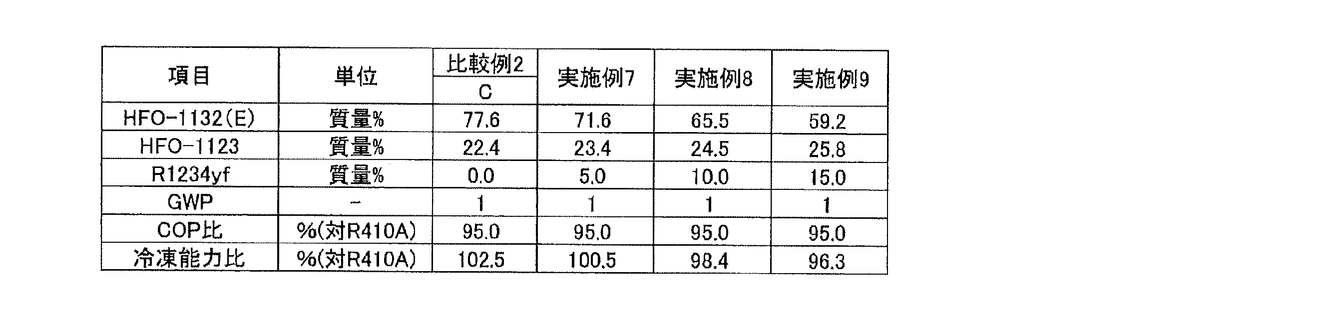

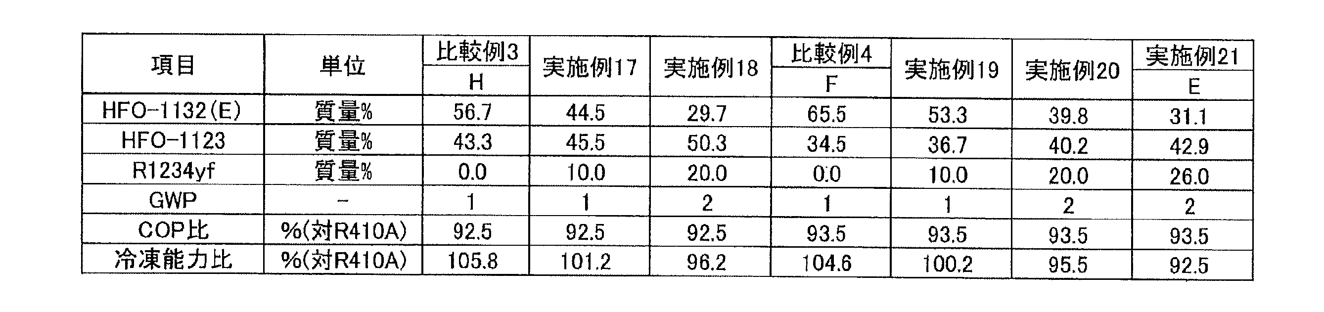
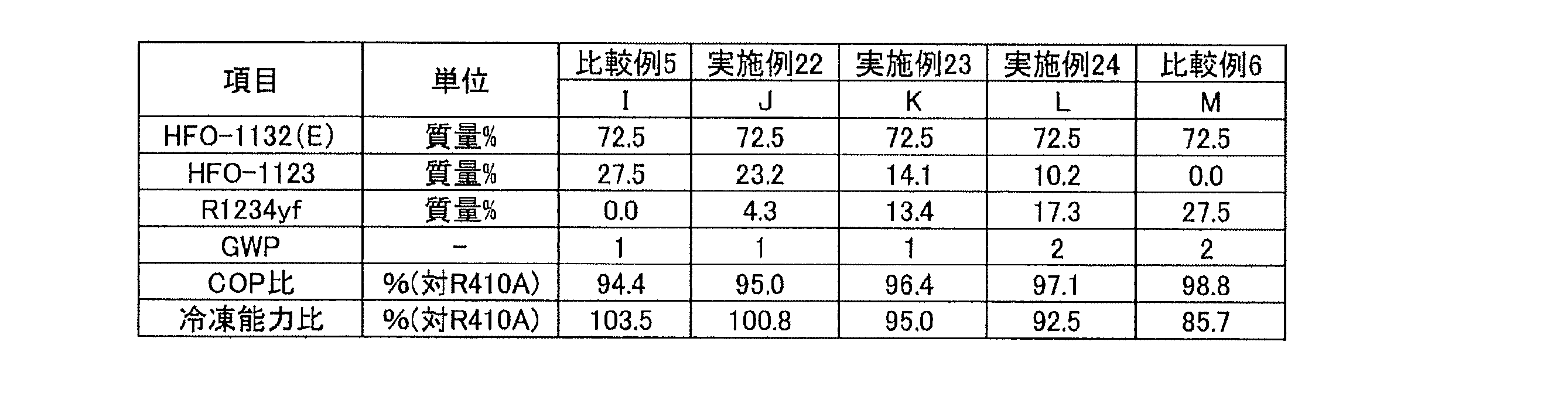
点D(87.6, 0.0, 12.4)、
点G(18.2, 55.1, 26.7)、
点H(56.7, 43.3, 0.0)及び
点O(100.0, 0.0, 0.0)
の4点をそれぞれ結ぶ線分OD、DG、GH及びHOで囲まれる図形(図1B)の範囲内又は前記線分OD、DG及びGH上にある場合(ただし、点O及び点Hは除く)、R410Aを基準とする冷凍能力比が92.5%以上となり、かつR410Aを基準とするCOP比が92.5%以上となることが判る。
点D(87.6, 0.0, 12.4)、
点E(31.1, 42.9, 26.0)、
点F(65.5, 34.5, 0.0)及び
点O(100.0, 0.0, 0.0)
の4点をそれぞれ結ぶ線分OD、DE、EF及びFOで囲まれる図形(図1B)の範囲内又は前記線分OD、DE及びEF上にある場合(ただし、点O及び点Fは除く)、R410Aを基準とする冷凍能力比が93.5%以上となり、かつR410Aを基準とするCOP比が93.5%以上となることが判る。
点A(93.4, 0.0, 6.6)、
点B(55.6, 26.6, 17.8)、
点C(77.6, 22.4, 0.0)及び
点O(100.0, 0.0, 0.0)
の4点をそれぞれ結ぶ線分OA、AB、BC及びCOで囲まれる図形(図1B)の範囲内又は前記線分OA、AB及びBC上にある場合(ただし、点O及び点Cは除く)、R410Aを基準とする冷凍能力比が95%以上となり、かつR410Aを基準とするCOP比が95%以上となることが判る。
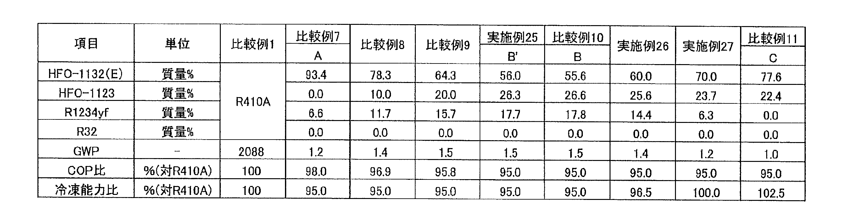
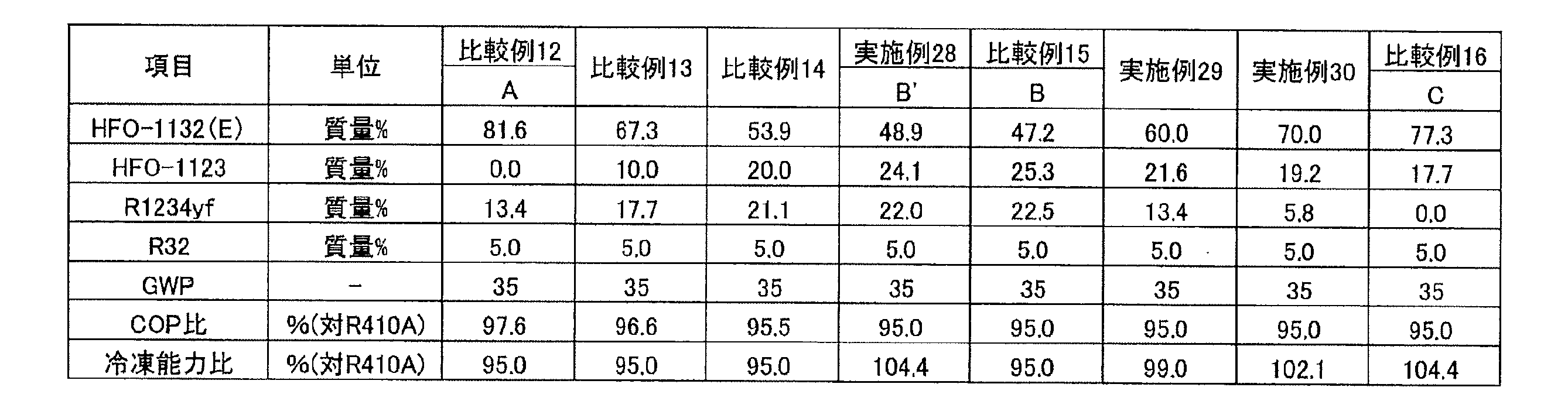
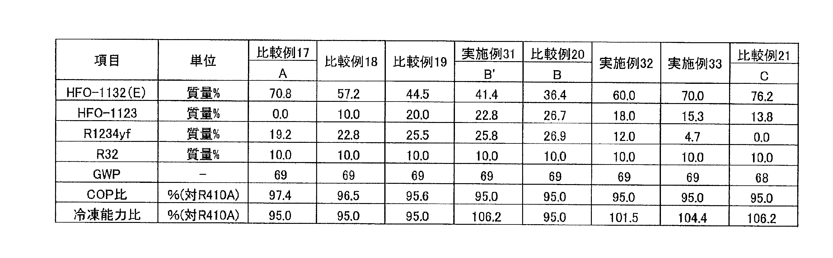

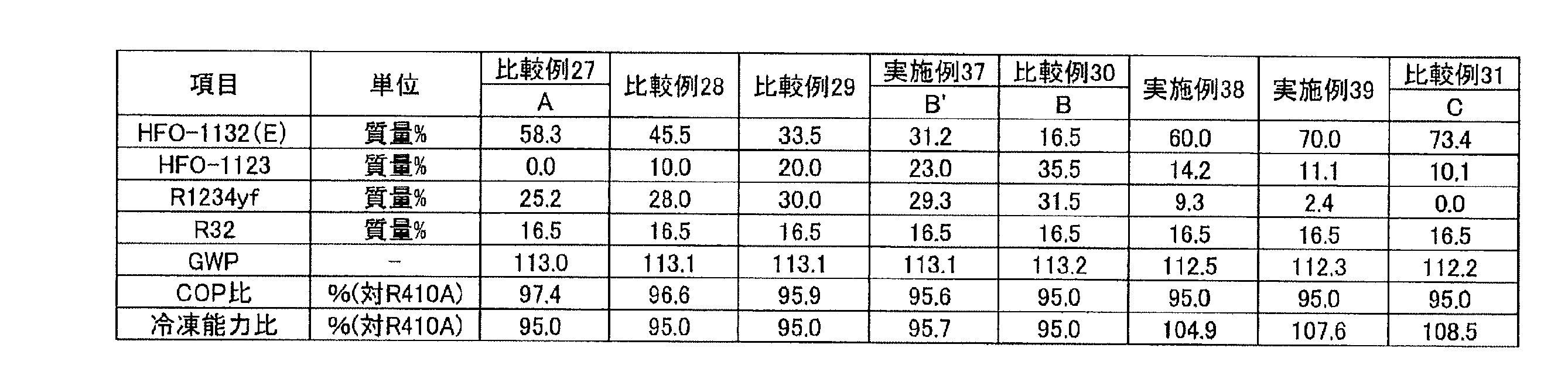


0<a≦10.0のとき、
点A(0.02a2-2.46a+93.4, 0, -0.02a2+2.46a+6.6)、
点B’(-0.008a2-1.38a+56, 0.018a2-0.53a+26.3, -0.01a2+1.91a+17.7)、
点C(-0.016a2+1.02a+77.6, 0.016a2-1.02a+22.4, 0)及び
点O(100.0, 0.0, 0.0)
の4点をそれぞれ結ぶ直線で囲まれる図形の範囲内又は前記直線OA、AB’及びB’C上にあり(ただし、点O及び点Cは除く)、
10.0<a≦16.5のとき、
点A(0.0244a2-2.5695a+94.056, 0, -0.0244a2+2.5695a+5.944)、
点B’(0.1161a2-1.9959a+59.749, 0.014a2-0.3399a+24.8, -0.1301a2+2.3358a+15.451)、
点C(-0.0161a2+1.02a+77.6, 0.0161a2-1.02a+22.4, 0)及び
点O(100.0, 0.0, 0.0)
の4点をそれぞれ結ぶ直線で囲まれる図形の範囲内又は前記直線OA、AB’及びB’C上にあり(ただし、点O及び点Cは除く)、又は
16.5<a≦21.8のとき、
点A(0.0161a2-2.3535a+92.742, 0, -0.0161a2+2.3535a+7.258)、
点B’(-0.0435a2-0.0435a+50.406, -0.0304a2+1.8991a-0.0661, 0.0739a2-1.8556a+49.6601)、
点C(-0.0161a2+0.9959a+77.851, 0.0161a2-0.9959a+22.149, 0)及び
点O(100.0, 0.0, 0.0)
の4点をそれぞれ結ぶ直線で囲まれる図形の範囲内又は前記直線OA、AB’及びB’C上にある(ただし、点O及び点Cは除く)本開示の冷媒は、R410Aを基準とする冷凍能力比が95%以上となり、かつR410Aを基準とするCOP比が95%以上となることが判る。

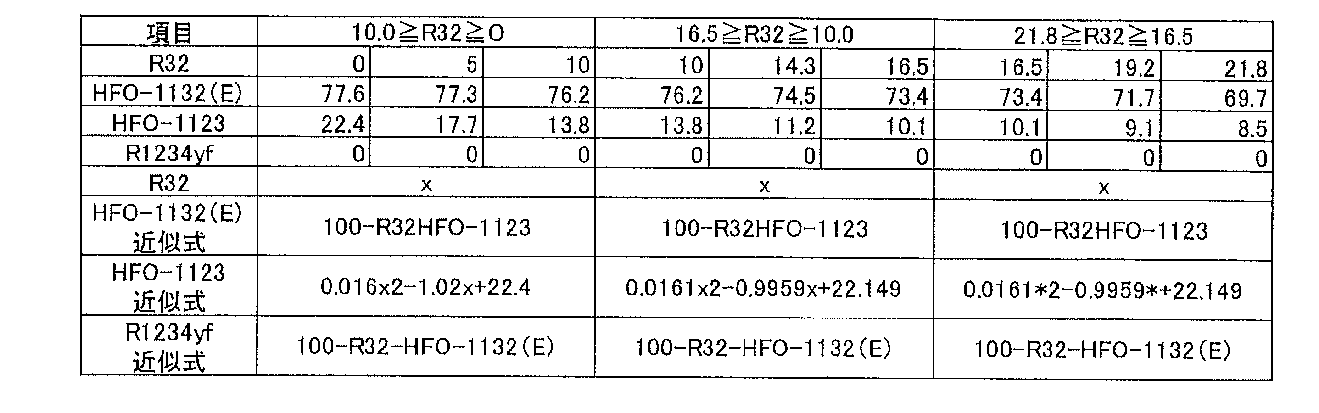
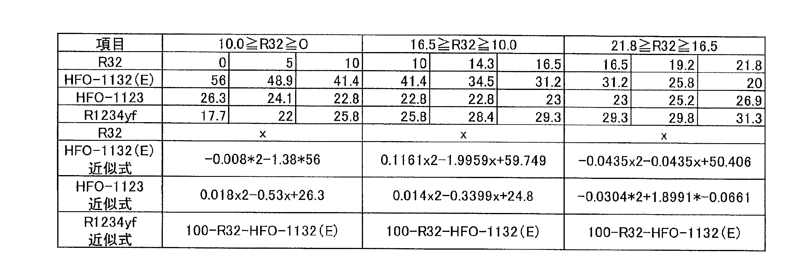
本開示の冷媒1Bは、
HFO-1132(E)及びHFO-1123の合計を、冷媒1Bの全体に対して99.5質量%以上含み、かつ
HFO-1132(E)を、冷媒1Bの全体に対して62.5質量%~72.5質量%含む、混合冷媒である。
以下に、冷媒1Bの実施例を挙げてさらに詳細に説明する。ただし、本開示の冷媒1Bは、これらの実施例に限定されるものではない。
蒸発温度 5℃
凝縮温度 45℃
過熱温度 1K
過冷却温度 5K
圧縮機効率 70%
COP =(冷凍能力又は暖房能力)/消費電力量
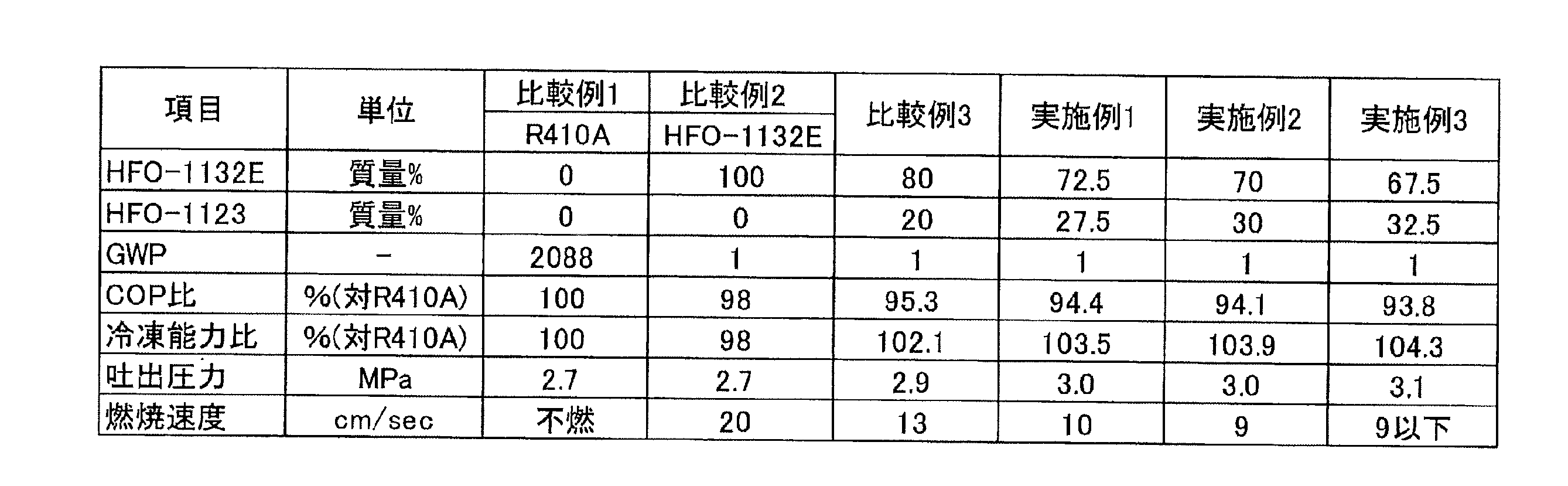
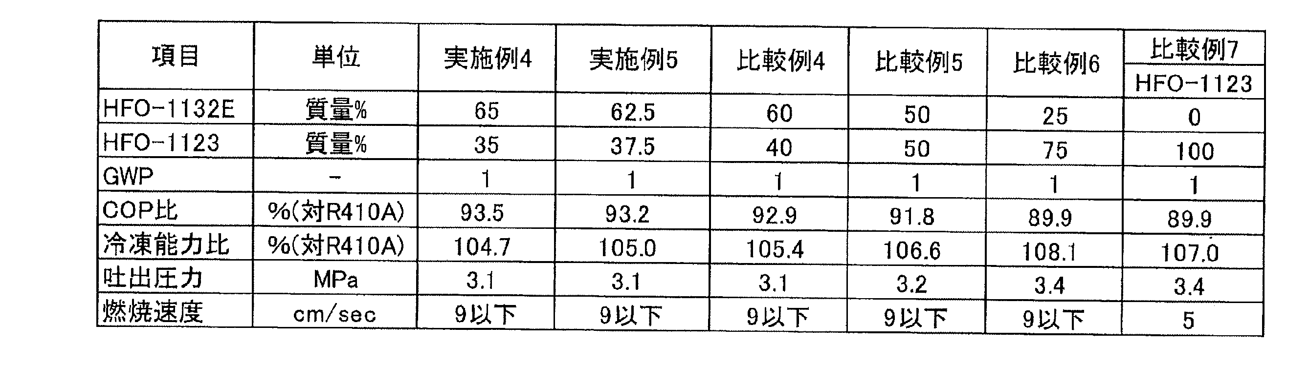
本開示の冷媒1Cは、HFO-1132(E)、R32及び2,3,3,3-テトラフルオロ-1-プロペン(R1234yf)を含む混合冷媒である。
点A(71.1, 0.0, 28.9)、
点C(36.5, 18.2, 45.3)、
点F(47.6, 18.3, 34.1)及び
点D(72.0, 0.0, 28.0)
の4点をそれぞれ結ぶ線分AC、CF、FD、及びDAで囲まれる図形の範囲内又は前記線分上にあり、
前記線分ACは、
座標(0.0181y2-2.2288y+71.096, y, -0.0181y2+1.2288y+28.904)
で表わされ、
前記線分FDは、
座標(0.02y2-1.7y+72, y, -0.02y2+0.7y+28)
で表わされ、かつ
前記線分CF及びDAが直線であるものであれば好ましい。本開示の冷媒1Cは、上記要件が満たされる場合、R410Aを基準とする冷凍能力比が85%以上となり、GWPが125以下となり、かつASHRAEの規格で微燃性(2Lクラス)となる。
点A(71.1, 0.0, 28.9)、
点B(42.6, 14.5, 42.9)、
点E(51.4, 14.6, 34.0)及び
点D(72.0, 0.0, 28.0)
の4点をそれぞれ結ぶ線分AB、BE、ED、及びDAで囲まれる図形の範囲内又は前記線分上にあり、
前記線分ABは、
座標(0.0181y2-2.2288y+71.096, y, -0.0181y2+1.2288y+28.904)
で表わされ、
前記線分EDは、
座標(0.02y2-1.7y+72, y, -0.02y2+0.7y+28)
で表わされ、かつ
前記線分BE及びDAが直線であるものであれば好ましい。本開示の冷媒1Cは、上記要件が満たされる場合、R410Aを基準とする冷凍能力比が85%以上となり、GWPが100以下となり、かつASHRAEの規格で微燃性(2Lクラス)となる。
点G(77.5, 6.9, 15.6)、
点I(55.1, 18.3, 26.6)及び
点J(77.5. 18.4, 4.1)
の3点をそれぞれ結ぶ線分GI、IJ及びJKで囲まれる図形の範囲内又は前記線分上にあり、前記線分GIは、
座標(0.02y2-2.4583y+93.396, y, -0.02y2+1.4583y+6.604)
で表わされ、かつ
前記線分IJ及びJKが直線であるものであれば好ましい。本開示の冷媒1Cは、上記要件が満たされる場合、R410Aを基準とする冷凍能力比が95%以上となり、GWPが100以下となり、かつ重合や分解などの変化を起こしにくく、安定性に優れている。
点G(77.5, 6.9, 15.6)、
点H(61.8, 14.6, 23.6)及び
点K(77.5, 14.6, 7.9)
の3点をそれぞれ結ぶ線分GH、HK及びKGで囲まれる図形の範囲内又は前記線分上にあり、前記線分GHは、
座標(0.02y2-2.4583y+93.396, y, -0.02y2+1.4583y+6.604)
で表わされ、かつ
前記線分HK及びKGが直線であるものであれば好ましい。本開示の冷媒1Cは、上記要件が満たされる場合、R410Aを基準とする冷凍能力比が95%以上となり、GWPが100以下となり、かつ重合や分解などの変化を起こしにくく、安定性に優れている。
以下に、冷媒1Cの実施例を挙げてさらに詳細に説明する。ただし、本開示の冷媒1Cは、これらの実施例に限定されるものではない。

R1234yfは、HFO-1132(E)及びR32のいずれよりも燃焼速度が低いことが判っているためである。
蒸発温度:5℃
凝縮温度:45℃
過熱度:1K
過冷却度;5K
Ecomp(圧縮仕事量):0.7kWh
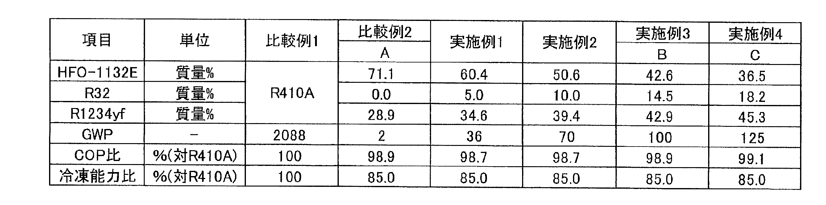
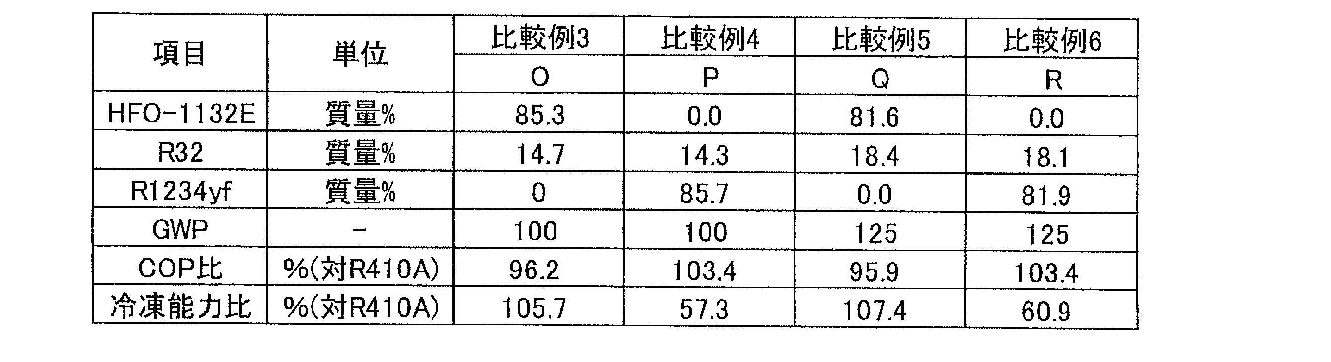


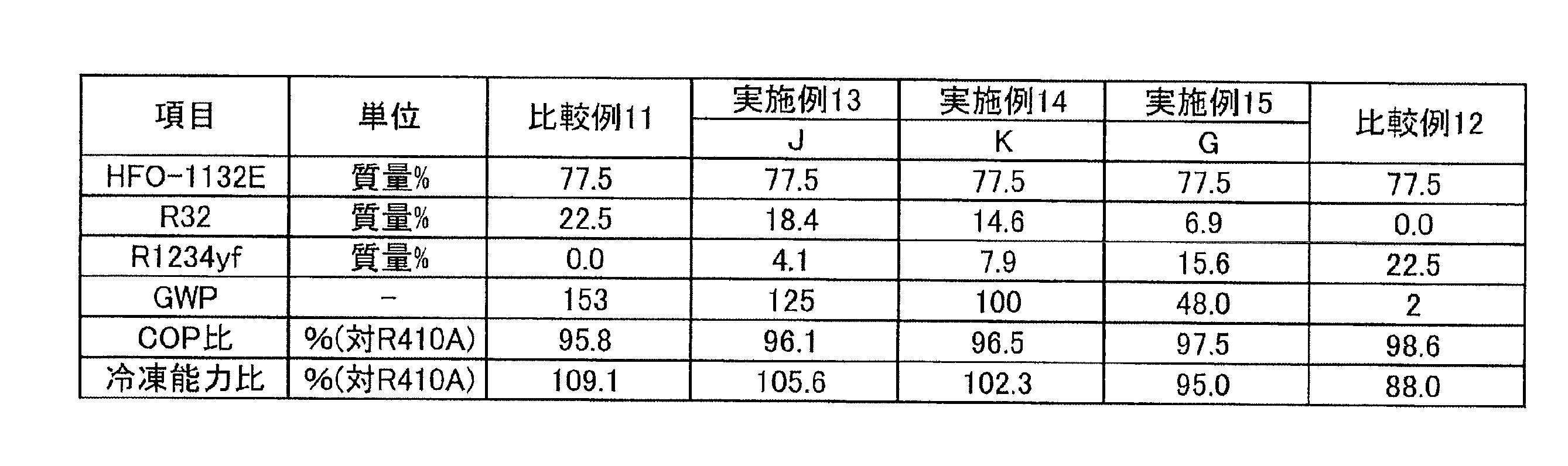
点A(71.1, 0.0, 28.9)、
点C(36.5, 18.2, 45.3)、
点F(47.6, 18.3, 34.1)及び
点D(72.0, 0.0, 28.0)
の4点をそれぞれ結ぶ線分AC、CF、FD、及びDAで囲まれる図形(図1J)の範囲内又は該線分上にある場合、R410Aを基準とする冷凍能力比が85%以上となり、GWPが125以下となり、かつASHRAEの規格で微燃性(2Lクラス)となることが判る。
点A(71.1, 0.0, 28.9)、
点B(42.6, 14.5, 42.9)、
点E(51.4, 14.6, 34.0)及び
点D(72.0, 0.0, 28.0)
の4点をそれぞれ結ぶ線分AB、BE、ED、及びDAで囲まれる図形(図1J)の範囲内又は該線分上にある場合、R410Aを基準とする冷凍能力比が85%以上となり、GWPが100以下となり、かつASHRAEの規格で微燃性(2Lクラス)となることが判る。
点G(77.5, 6.9, 15.6)、
点I(55.1, 18.3, 26.6)及び
点J(77.5. 18.4, 4.1)
の3点をそれぞれ結ぶ線分GI、IJ及びJKで囲まれる図形(図1J)の範囲内又は該線分上にある場合、R410Aを基準とする冷凍能力比が95%以上となり、GWPが125以下となり、かつ重合や分解などの変化を起こしにくく、安定性に優れることが判る。
点G(77.5, 6.9, 15.6)、
点H(61.8, 14.6, 23.6)及び
点K(77.5, 14.6, 7.9)
の3点をそれぞれ結ぶ線分GH、HK及びKGで囲まれる図形(図1J)の範囲内又は該線分上にある場合、R410Aを基準とする冷凍能力比が95%以上となり、GWPが100以下となり、かつ重合や分解などの変化を起こしにくく、安定性に優れることが判る。
本開示の冷媒1Dは、HFO-1132(E)、HFO-1123及びR32を含む混合冷媒である。
点O(100.0, 0.0, 0.0)、
点C’(56.7, 43.3, 0.0)、
点D’(52.2, 38.3, 9.5)、
点E’(41.8, 39.8, 18.4)及び
点A’(81.6, 0.0, 18.4)
の5点をそれぞれ結ぶ線分OC’、C’D’、D’E’、E’A’及びA’Oで囲まれる図形の範囲内又は前記線分C’D’、D’E’及びE’A’上にあり(ただし、点C’及びA’を除く)、
前記線分C’D’は、
座標(-0.0297z2-0.1915z+56.7, 0.0297z2+1.1915z+43.3, z)
で表わされ、
前記線分D’E’は、
座標(-0.0535z2+0.3229z+53.957, 0.0535z2+0.6771z+46.043, z)
で表わされ、かつ
前記線分OC’、E’A’及びA’Oが直線であるものであれば好ましい。本開示の冷媒1Dは、上記要件が満たされる場合、R410Aを基準とするCOP比が92.5%以上となり、かつGWPが125以下となる。
点O(100.0, 0.0, 0.0)、
点C(77.7, 22.3, 0.0)、
点D(76.3, 14.2, 9.5)、
点E(72.2, 9.4, 18.4)及び
点A’(81.6, 0.0, 18.4)
の5点をそれぞれ結ぶ線分OC、CD、DE、EA’及びA’Oで囲まれる図形の範囲内又は前記線分CD、DE及びEA’上にあり(ただし、点C及びA’を除く)、
前記線分CDEは、
座標(-0.017z2+0.0148z+77.684, 0.017z2+0.9852z+22.316, z)
で表わされ、かつ
前記線分OC、EA’及びA’Oが直線であるものであれば好ましい。本開示の冷媒1Dは、上記要件が満たされる場合、R410Aを基準とするCOP比が95%以上となり、かつGWPが125以下となる。
点O(100.0, 0.0, 0.0)、
点C’(56.7, 43.3, 0.0)、
点D’(52.2, 38.3, 9.5)及び
点A(90.5, 0.0, 9.5)
の5点をそれぞれ結ぶ線分OC’、C’D’、D’A及びAOで囲まれる図形の範囲内又は前記線分C’D’及びD’A上にあり(ただし、点C’及びAを除く)、
前記線分C’D’は、
座標(-0.0297z2-0.1915z+56.7, 0.0297z2+1.1915z+43.3, z)
で表わされ、かつ
前記線分OC’、D’A及びAOが直線であるものであれば好ましい。本開示の冷媒1Dは、上記要件が満たされる場合、R410Aを基準とするCOP比が93.5%以上となり、かつGWPが65以下となる。
点O(100.0, 0.0, 0.0)、
点C(77.7, 22.3, 0.0)、
点D(76.3, 14.2, 9.5)、
点A(90.5, 0.0, 9.5)
の5点をそれぞれ結ぶ線分OC、CD、DA及びAOで囲まれる図形の範囲内又は前記線分CD及びDA上にあり(ただし、点C及びAを除く)、
前記線分CDは、
座標(-0.017z2+0.0148z+77.684, 0.017z2+0.9852z+22.316, z)
で表わされ、かつ
前記線分OC、DA及びAOが直線であるものであれば好ましい。本開示の冷媒1Dは、上記要件が満たされる場合、R410Aを基準とするCOP比が95%以上となり、かつGWPが65以下となる。
以下に、冷媒1Dの実施例を挙げてさらに詳細に説明する。ただし、本開示の冷媒1Dは、これらの実施例に限定されるものではない。
凝縮温度:45℃
過熱度:1K
過冷却度;5K
Ecomp(圧縮仕事量):0.7kWh
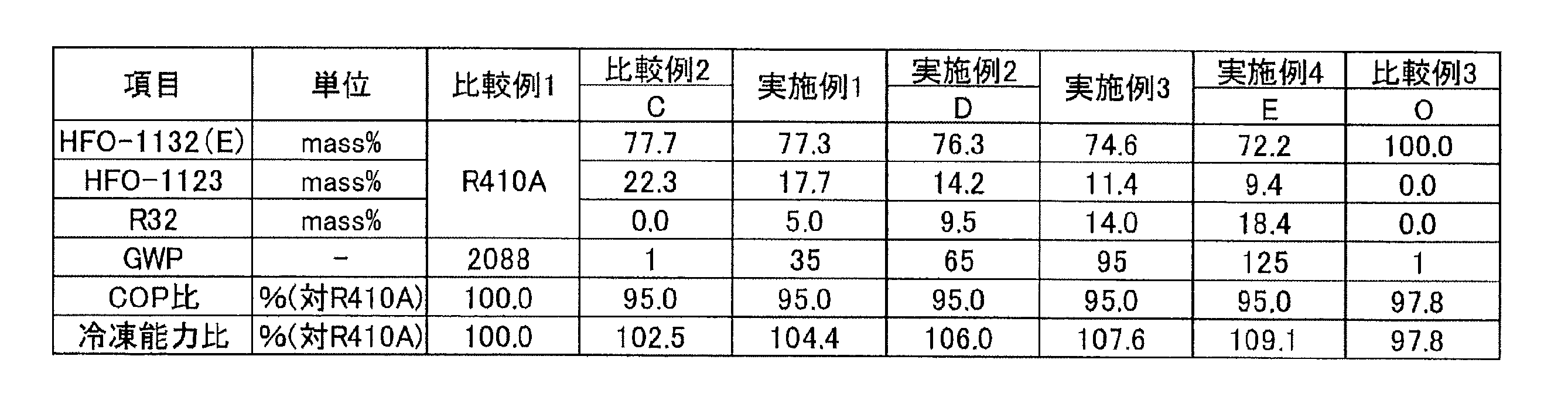
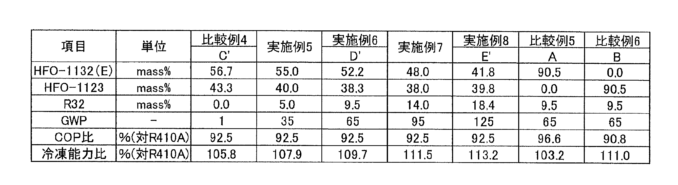

点O(100.0, 0.0, 0.0)、
点C’(56.7, 43.3, 0.0)、
点D’(52.2, 38.3, 9.5)、
点E’(41.8, 39.8, 18.4)及び
点A’(81.6, 0.0, 18.4)
の5点をそれぞれ結ぶ線分OC’、C’D’、D’E’、E’A’及びA’Oで囲まれる図形(図1K)の範囲内又は前記線分C’D’、D’E’及びE’A’上にある場合(ただし、点C’及びA’を除く)、R410Aを基準とするCOP比が92.5%以上となり、かつGWPが125以下となることが判る。
点O(100.0, 0.0, 0.0)、
点C(77.7, 22.3, 0.0)、
点D(76.3, 14.2, 9.5)、
点E(72.2, 9.4, 18.4)及び
点A’(81.6, 0.0, 18.4)
の5点をそれぞれ結ぶ線分OC、CD、DE、EA’及びA’Oで囲まれる図形(図1K)の範囲内又は前記線分CD、DE及びEA’上にある場合(ただし、点C及びA’を除く)、R410Aを基準とするCOP比が95%以上となり、かつGWPが125以下となることが判る。
点O(100.0, 0.0, 0.0)、
点C’(56.7, 43.3, 0.0)、
点D’(52.2, 38.3, 9.5)及び
点A(90.5, 0.0, 9.5)
の5点をそれぞれ結ぶ線分OC’、C’D’、D’A及びAOで囲まれる図形(図1K)の範囲内又は前記線分C’D’及びD’A上にある場合(ただし、点C’及びAを除く)、R410Aを基準とするCOP比が92.5%以上となり、かつGWPが65以下となることが判る。
点O(100.0, 0.0, 0.0)、
点C(77.7, 22.3, 0.0)、
点D(76.3, 14.2, 9.5)、
点A(90.5, 0.0, 9.5)
の5点をそれぞれ結ぶ線分OC、CD、DA及びAOで囲まれる図形(図1K)の範囲内又は前記線分CD及びDA上にある場合(ただし、点C及びAを除く)、R410Aを基準とするCOP比が95%以上となり、かつGWPが65以下となることが判る。
本開示の冷媒1Eは、CO2、並びにR32、HFO-1132(E)及びR1234yfを含む混合冷媒である。
点I(0.0, 72.0, 28.0-w)
点J(18.3, 48.5, 33.2-w)
点K(36.8, 35.6, 27.6-w)
点L(51.7, 28.9, 19.4-w)
点B’’(-1.5278w2+2.75w+50.5, 0.0, 1.5278w2-3.75w+49.5)
点D(-2.9167w+40.317, 0.0, 1.9167w+59.683)
点C(0.0, -4.9167w+58.317, 3.9167w+41.683)
の7点をそれぞれ結ぶ曲線IJ、曲線JK及び曲線KL、並びに直線LB’’、直線B’’D、直線DC及び直線CIで囲まれる図形の範囲内又は前記線分上にあり(ただし、直線B’’D及び直線CIの上の点は除く)、
1.2<w≦4.0のとき、
点I(0.0, 72.0, 28.0-w)
点J(18.3, 48.5, 33.2-w)
点K(36.8, 35.6, 27.6-w)
点L(51.7, 28.9, 19.4-w)
点B’’(51.6, 0.0, 48.4-w)
点D(-2.8226w+40.211, 0.0, 1.8226w+59.789)
点C(0.0, 0.1081w2-5.169w+58.447, -0.1081w2+4.169w+41.553)
の7点をそれぞれ結ぶ曲線IJ、曲線JK及び曲線KL、並びに直線LB’’、直線B’’D、直線DC及び直線CIで囲まれる図形の範囲内又は前記線分上にあり(ただし、直線B’’D及び直線CIの上の点は除く)、
4.0<w≦7.0のとき、
点I(0.0, 72.0, 28.0-w)
点J(18.3, 48.5, 33.2-w)
点K(36.8, 35.6, 27.6-w)
点L(51.7, 28.9, 19.4-w)
点B’’(51.6, 0.0, 48.4-w)
点D(-2.8w+40.1, 0.0, 1.8w+59.9)
点C(0.0, 0.0667w2-4.9667w+58.3, -0.0667w2+3.9667w+41.7)
の7点をそれぞれ結ぶ曲線IJ、曲線JK及び曲線KL、並びに直線LB’’、直線B’’D、直線DC及び直線CIで囲まれる図形の範囲内又は前記線分上にあり(ただし、直線B’’D及び直線CIの上の点は除く)、かつ
曲線IJは、
座標(x, 0.0236x2-1.716x+72, -0.0236x2+0.716x+28-w)
で表わされ、
曲線JKは、
座標(x, 0.0095x2-1.2222x+67.676, -0.0095x2+0.2222x+32.324-w)
で表わされ、
曲線KLは、
座標(x, 0.0049x2-0.8842x+61.488, -0.0049x2-0.1158x+38.512)
で表わされるものである。
0<w≦1.2のとき、
点I(0.0, 72.0, 28.0-w)
点J(18.3, 48.5, 33.2-w)
点K(36.8, 35.6, 27.6-w)
点F(-0.0833w+36.717, -4.0833w+5.1833, 3.1666w+58.0997)
点C(0.0, -4.9167w+58.317, 3.9167w+41.683)
の5点をそれぞれ結ぶ曲線IJ及び曲線JK、並びに直線KF、直線FC及び直線CIで囲まれる図形の範囲内又は前記線分上にあり(ただし、直線CIの上の点は除く)、
1.2<w≦1.3のとき、
点I(0.0, 72.0, 28.0-w)
点J(18.3, 48.5, 33.2-w)
点K(36.8, 35.6, 27.6-w)
点F(36.6, -3w+3.9, 2w+59.5)
点C(0.0, 0.1081w2-5.169w+58.447, -0.1081w2+4.169w+41.553)
の5点をそれぞれ結ぶ曲線IJ及び曲線JK、並びに直線KF、直線FC及び直線CIで囲まれる図形の範囲内又は前記線分上にあり(ただし、直線CIの上の点は除く)、
1.3<w≦4.0のとき、
点I(0.0, 72.0, 28.0-w)
点J(18.3, 48.5, 33.2-w)
点K(36.8, 35.6, 27.6-w)
点B’(36.6, 0.0, -w+63.4)
点D(-2.8226w+40.211, 0.0, 1.8226w+59.789)
点C(0.0, 0.1081w2-5.169w+58.447, -0.1081w2+4.169w+41.553)
の6点をそれぞれ結ぶ曲線IJ及び曲線JK、並びに直線KB’、直線B’D、直線DC及び直線CIで囲まれる図形の範囲内又は前記線分上にあり(ただし、直線CIの上の点は除く)、
4.0<w≦7.0のとき、
点I(0.0, 72.0, 28.0-w)
点J(18.3, 48.5, 33.2-w)
点K(36.8, 35.6, 27.6-w)
点B’(36.6, 0.0, -w+63.4)
点D(-2.8w+40.1, 0.0, 1.8w+59.9)
点C(0.0, 0.0667w2-4.9667w+58.3, -0.0667w2+3.9667w+41.7)
の6点をそれぞれ結ぶ曲線IJ及び曲線JK、並びに直線KB’、直線B’D、直線DC及び直線CIで囲まれる図形の範囲内又は前記線分上にあり(ただし、直線CIの上の点は除く)、かつ曲線IJは、
座標(x, 0.0236x2-1.716x+72, -0.0236x2+0.716x+28-w)
で表わされ、
曲線JKは、
座標(x, 0.0095x2-1.2222x+67.676, -0.0095x2+0.2222x+32.324-w)
で表わされるものであれば好ましい。本開示の冷媒1Eは、上記要件が満たされる場合、R410Aを基準とする冷凍能力比が80%以上となり、GWPが250以下となり、かつWCF微燃となる。
0<w≦1.2のとき、
点I(0.0, 72.0, 28.0-w)
点J(18.3, 48.5, 33.2-w)
点E(18.2, -1.1111w2-3.1667w+31.9, 1.1111w2+2.1667w+49.9)
点C(0.0, -4.9167w+58.317, 3.9167w+41.683)
の4点をそれぞれ結ぶ曲線IJ及び曲線JK、並びに直線KF、直線FC及び直線CIで囲まれる図形の範囲内又は前記線分上にあり(ただし、直線CIの上の点は除く)、
1.2<w≦4.0のとき、
点I(0.0, 72.0, 28.0-w)
点J(18.3, 48.5, 33.2-w)
点E(-0.0365w+18.26, 0.0623w2-4.5381w+31.856, -0.0623w2+3.5746w+49.884)
点C(0.0, 0.1081w2-5.169w+58.447, -0.1081w2+4.169w+41.553)
の4点をそれぞれ結ぶ曲線IJ及び曲線JK、並びに直線KF、直線FC及び直線CIで囲まれる図形の範囲内又は前記線分上にあり(ただし、直線CIの上の点は除く)、
4.0<w≦7.0のとき、
点I(0.0, 72.0, 28.0-w)
点J(18.3, 48.5, 33.2-w)
点E(18.1, 0.0444w2-4.3556w+31.411, -0.0444w2+3.3556w+50.489)
点C(0.0, 0.0667w2-4.9667w+58.3, -0.0667w2+3.9667w+41.7)
の4点をそれぞれ結ぶ曲線IJ及び曲線JK、並びに直線KF、直線FC及び直線CIで囲まれる図形の範囲内又は前記線分上にあり(ただし、直線CIの上の点は除く)、かつ
曲線IJは、
座標(x, 0.0236x2-1.716x+72, -0.0236x2+0.716x+28-w)
で表わされるものであれば好ましい。本開示の冷媒1Eは、上記要件が満たされる場合、R410Aを基準とする冷凍能力比が80%以上となり、GWPが125以下となり、かつWCF微燃となる。
0<w≦0.6のとき、
点G(-5.8333w2-3.1667w+22.2, 7.0833w2+1.4167w+26.2, -1.25w2+0.75w+51.6)
点O(36.8, 0.8333w2+1.8333w+22.6, -0.8333w2-2.8333w+40.6)
点P(51.7, 1.1111w2+20.5, -1.1111w2-w+27.8)
点B’’(-1.5278w2+2.75w+50.5, 0.0, 1.5278w2-3.75w+49.5)
点D(-2.9167w+40.317, 0.0, 1.9167w+59.683)
の5点をそれぞれ結ぶ曲線GO及び曲線OP、並びに直線PB’’、直線B’’D及び直線DGで囲まれる図形の範囲内又は前記線分上にあり(ただし、直線B’’Dの上の点は除く)、
0.6<w≦1.2のとき、
点G(-5.8333w2-3.1667w+22.2, 7.0833w2+1.4167w+26.2, -1.25w2+0.75w+51.6)
点N(18.2, 0.2778w2+3w+27.7, -0.2778w2-4w+54.1)
点O(36.8, 0.8333w2+1.8333w+22.6, -0.8333w2-2.8333w+40.6)
点P(51.7, 1.1111w2+20.5, -1.1111w2-w+27.8)
点B’’(-1.5278w2+2.75w+50.5, 0.0, 1.5278w2-3.75w+49.5)
点D(-2.9167w+40.317, 0.0, 1.9167w+59.683)
の6点をそれぞれ結ぶ曲線GN、曲線NO、及び曲線OP、並びに直線PB’’、直線B’’D及び直線DGで囲まれる図形の範囲内又は前記線分上にあり(ただし、直線B’’Dの上の点は除く)、
かつ
曲線GOは、
0<w≦0.6のとき、
座標(x, (0.00487w2-0.0059w+0.0072)x2+(-0.279w2+0.2844w-0.6701)x+3.7639w2-0.2467w+37.512, 100-w-x-y)
で表わされ、
曲線GNは、
0.6<w≦1.2のとき、
座標(x, (0.0122w2-0.0113w+0.0313)x2+(-0.3582w2+0.1624w-1.4551)x+2.7889w2+3.7417w+43.824 , 100-w-x-y)
で表わされ、
曲線NOは、
0.6<w≦1.2のとき、
座標(x, (0.00487w2-0.0059w+0.0072)x2+(-0.279w2+0.2844w-0.6701)x+3.7639w2-0.2467w+37.512, 100-w-x-y)
で表され、
曲線OPは、
0<w≦1.2のとき、
座標(x, (0.0074w2-0.0133w+0.0064)x2+(-0.5839w2+1.0268w-0.7103)x+11.472w2-17.455w+40.07, 100-w-x-y)
で表わされ、
1.2<w≦4.0のとき、
点M(0.0, -0.3004w2+2.419w+55.53, 0.3004w2-3.419w+44.47)
点W(10.0, -0.3645w2+3.5024w+44.422, 0.3645w2-4.5024w+55.57)
点N(18.2, -0.3773w2+3.319w+28.26, 0.3773w2-4.319w+53.54)
点O(36.8, -0.1392w2+1.4381w+24.475, 0.1392w2-2.4381w+38.725)
点P(51.7, -0.2381w2+1.881w+20.186, 0.2381w2-2.881w+28.114)
点B’’(51.6, 0.0, -w+48.4)
点D(-2.8226w+40.211, 0.0, 1.8226w+59.789)
点C(0.0, 0.1081w2-5.169w+58.447, -0.1081w2+4.169w+41.553)
の8点をそれぞれ結ぶ曲線MW、曲線WN、曲線NO及び曲線OP、並びに直線PB’’、直線B’’D、直線DC及び直線CMで囲まれる図形の範囲内又は前記線分上にあり(ただし、直線B’’D及び直線CMの上の点は除く)、かつ
曲線MWは、
座標(x, (0.0043w2-0.0359w+0.1509)x2+(-0.0493w2+0.4669w-3.6193)x-0.3004w2+2.419w+55.53, 100-w-x-y)
で表わされ、
曲線WNは、
座標(x, (0.0055w2-0.0326w+0.0665)x2+(-0.1571w2+0.8981w-2.6274)x+0.6555w2-2.2153w+54.044, 100-w-x-y)
で表わされ、
曲線NOは、
座標(x, (-0.00062w2+0.0036w+0.0037)x2+(0.0375w2-0.239w-0.4977)x-0.8575w2+6.4941w+36.078, 100-w-x-y)
で表わされ、
曲線OPは、
座標(x, (-0.000463w2+0.0024w-0.0011)x2+(0.0457w2-0.2581w-0.075)x-1.355w2+8.749w+27.096, 100-w-x-y)
で表わされ、
4.0<w≦7.0のとき、
点M(0.0, -0.0667w2+0.8333w+58.133, 0.0667w2-1.8333w+41.867)
点W(10.0, -0.0667w2+1.1w+39.267, 0.0667w2-2.1w+50.733)
点N(18.2, -0.0889w2+1.3778w+31.411, 0.0889w2-2.3778w+50.389)
点O(36.8, -0.0444w2+0.6889w+25.956, 0.0444w2-1.6889w+37.244)
点P(51.7, -0.0667w2+0.8333w+21.633, 0.0667w2-1.8333w+26.667)
点B’’(51.6, 0.0, -w+48.4)
点D(-2.8w+40.1, 0.0, 1.8w+59.9)
点C(0.0, 0.0667w2-4.9667w+58.3, -0.0667w2+3.9667w+41.7)
の8点をそれぞれ結ぶ曲線MW、曲線WN、曲線NO及び曲線OP、並びに直線PB’’、直線B’’D、直線DC及び直線CMで囲まれる図形の範囲内又は前記線分上にあり(ただし、直線B’’D及び直線CMの上の点は除く)、かつ
曲線MWは、
座標(x, (0.00357w2-0.0391w+0.1756)x2+(-0.0356w2+0.4178w-3.6422)x-0.0667w2+0.8333w+58.103, 100-w-x-y)
で表わされ、
曲線WNは、
座標(x, (-0.002061w2+0.0218w-0.0301)x2+(0.0556w2-0.5821w-0.1108)x-0.4158w2+4.7352w+43.383, 100-w-x-y)
で表わされ、
曲線NOは、
座標(x, 0.0082x2+(0.0022w2-0.0345w-0.7521)x-0.1307w2+2.0247w+42.327, 100-w-x-y)
で表わされ、
曲線OPは、
座標(x, (-0.0006258w2+0.0066w-0.0153)x2+(0.0516w2-0.5478w+0.9894)x-1.074w2+11.651w+10.992, 100-w-x-y)
で表わされるものであれば好ましい。本開示の冷媒1Eは、上記要件が満たされる場合、R410Aを基準とする冷凍能力比が80%以上となり、GWPが350以下となり、かつASHRAE微燃となる。
0<w≦0.6のとき、
点G(-5.8333w2-3.1667w+22.2, 7.0833w2-1.4167w+26.2, -1.25w2+3.5834w+51.6)
点O(36.8, 0.8333w2+1.8333w+22.6, -0.8333w2-2.8333w+40.6)
点F(-0.0833w+36.717, -4.0833w+5.1833, 3.1666w+58.0997)
の3点をそれぞれ結ぶ曲線GO、並びに直線OF及び直線FGで囲まれる図形の範囲内又は前記線分上にあり、かつ
曲線GOは、
座標(x, (0.00487w2-0.0059w+0.0072) x2+(-0.279w2+0.2844w-0.6701)x+3.7639w2-0.2467w+37.512, 100-w-x-y)
で表わされ、
0.6<w≦1.2のとき、
点G(-5.8333w2-3.1667w+22.2, 7.0833w2-1.4167w+26.2, -1.25w2+3.5834w+51.6)
点N(18.2, 0.2778w2+3.0w+27.7, -0.2.778w2-4.0w+54.1)
点O(36.8, 0.8333w2+1.8333w+22.6, -0.8333w2-2.8333w+40.6)
点F(-0.0833w+36.717, -4.0833w+5.1833, 3.1666w+58.0997)
の4点をそれぞれ結ぶ曲線GN及び曲線NO、並びに直線OF及び直線FGで囲まれる図形の範囲内又は前記線分上にあり、かつ
曲線GNは、
0.6<w≦1.2のとき、
座標(x, (0.0122w2-0.0113w+0.0313)x2+(-0.3582w2+0.1624w-1.4551)x+2.7889w2+3.7417w+43.824, 100-w-x-y)
で表わされ、
曲線NOは、
0.6<w≦1.2のとき、
座標(x, (0.00487w2-0.0059w+0.0072)x2+(-0.279w2+0.2844w-0.6701)x+3.7639w2-0.2467w+37.512, 100-w-x-y)
で表され
1.2<w≦1.3のとき、
点M(0.0, -0.3004w2+2.419w+55.53, 0.3004w2-3.419w+44.47)
点W(10.0, -0.3645w2+3.5024w34.422, 0.3645w2-4.5024w+55.578)
点N(18.2, -0.3773w2+3.319w+28.26, 0.3773w2-4.319w+53.54)
点O(36.8, -0.1392w2+1.4381w+24.475, 0.1392w2-2.4381w+38.725)
点F(36.6, -3w+3.9, 2w+59.5)
点C(0.1081w2-5.169w+58.447, 0.0, -0.1081w2+4.169w+41.553)
の6点をそれぞれ結ぶ曲線MW、曲線WN及び曲線NO、並びに直線OF及び直線FC及び直線CMで囲まれる図形の範囲内又は前記線分上にあり(ただし、直線CMの上の点は除く)、かつ
曲線MWは、
座標(x, (0.0043w2-0.0359w+0.1509)x2+(-0.0493w2+0.4669w-3.6193)x-0.3004w2+2.419w+55.53, 100-w-x-y)
で表わされ、
曲線WNは、
座標(x, (0.0055w2-0.0326w+0.0665)x2+(-0.1571w2+0.8981w-2.6274)x+0.6555w2-2.2153w+54.044, 100-w-x-y)
で表わされ、
曲線NOは、
座標(x, (-0.00062w2+0.0036w+0.0037)x2+(0.0375w2-0.239w-0.4977)x-0.8575w2+6.4941w+36.078, 100-w-x-y)
で表わされ、
1.3<w≦4.0のとき、
点M(0.0, -0.3004w2+2.419w+55.53, 0.3004w2-3.419w+44.47)
点W(10.0, -0.3645w2+3.5024w+34.422, 0.3645w2-4.5024w+55.578)
点N(18.2, -0.3773w2+3.319w+28.26, 0.3773w2-4.319w+53.54)
点O(36.8, -0.1392w2+1.4381w+24.475, 0.1392w2-2.4381w+38.725)
点B’(36.6, 0.0, -w+63.4)
点D(-2.8226w+40.211, 0.0, 1.8226w+59.789)
点C(0.0, 0.1081w2-5.169w+58.447, -0.1081w2+4.169w+41.553)
の7点をそれぞれ結ぶ曲線MW、曲線WN及び曲線NO、並びに直線OB’、直線B’D、及び直線DC及び直線CMで囲まれる図形の範囲内又は前記線分上にあり(ただし、直線CMの上の点は除く)、かつ
曲線MWは、
座標(x, (0.0043w2-0.0359w+0.1509)x2+(-0.0493w2+0.4669w-3.6193)x-0.3004w2+2.419w+55.53, 100-w-x-y)
で表わされ、
曲線WNは、
座標(x, (0.0055w2-0.0326w+0.0665)x2+(-0.1571w2+0.8981w-2.6274)x+0.6555w2-2.2153w+54.044, 100-w-x-y)
曲線NOは、
座標(x, (-0.00062w2+0.0036w+0.0037)x2+(0.0457w2-0.2581w-0.075)x-1.355w2+8.749w+27.096, 100-w-x-y)
で表わされ、
4.0<w≦7.0のとき、
点M(0.0, -0.0667w2+0.8333w58.133, 0.0667w2-1.8333w+41.867)
点W(10.0, -0.0667w2+1.1w+39.267, 0.0667w2-2.1w+50.733)
点N(18. 2, -0.0889w2+1.3778w+31.411, 0.0889w2-2.3778w+50.389)
点O(36.8, -0.0444w2+0.6889w+25.956, 0.0444w2-1.6889w+37.244)
点B’(36.6, 0.0, -w+63.4)
点D(-2.8w+40. 1, 0.0, 1.8w+59.9)
点C(0.0, 0.0667w2-4.9667w+58.3, -0.0667w2+3.9667w+41.7)
の7点をそれぞれ結ぶ曲線MW、曲線WN及び曲線NO、並びに直線OB’、直線B’D、及び直線DC及び直線CMで囲まれる図形の範囲内又は前記線分上にあり(ただし、直線CMの上の点は除く)、かつ
曲線MWは、
座標(x, (0.00357w2-0.0391w+0.1756)x2+(-0.0356w2+0.4178w-3.6422)x-0.0667w2+0.8333w+58.103, 100-w-x-y)
で表わされ、
曲線WNは、
座標(x, (-0.002061w2+0.0218w-0.0301)x2+(0.0556w2-0.5821w-0.1108)x-0.4158w2+4.7352w+43.383, 100-w-x-y)
曲線NOは、
座標(x, (0.0082x2+(0.0022w2-0.0345w-0.7521)x-0.1307w2+2.0247w+42.327, 100-w-x-y)
で表わされるものであれば好ましい。本開示の冷媒1Eは、上記要件が満たされる場合、R410Aを基準とする冷凍能力比が80%以上となり、GWPが250以下となり、かつASHRAE微燃となる。
1.2<w≦4.0のとき、
点M(0.0, -0.3004w2+2.419w+55.53, 0.3004w2-3.419w+44.47)
点W(10.0, -0.3645w2+3.5024w+34.422, 0.3645w2-4.5024w+55.578)
点N(18.2, -0.3773w2+3.319w+28.26, 0.3773w2-4.319w+53.54)
点E(-0.0365w+18.26, 0.0623w2-4.5381w+31.856, -0.0623w2+3.5746w+49.884)
点C(0.0, 0.1081w2-5.169w+58.447, -0.1081w2+4.169w+41.553)
の5点をそれぞれ結ぶ曲線MW及び曲線WN、並びに直線NE、直線EC及び直線CMで囲まれる図形の範囲内又は前記線分上にあり(ただし、直線CMの上の点は除く)、かつ
曲線MWは、
座標(x, (0.0043w2-0.0359w+0.1509)x2+(-0.0493w2+0.4669w-3.6193)x-0.3004w2+2.419w+55.53, 100-w-x-y)
で表わされ、
曲線WNは、
座標(x, (0.0055w2-0.0326w+0.0665)x2+(-0.1571w2+0.8981w-2.6274)x+0.6555w2-2.2153w+54.044, 100-w-x-y)
で表わされ、
4.0<w≦7.0のとき、
点M(0.0, -0.0667w2+0.8333w+58.133, 0.0667w2-1.8333w+41.867)
点W(10.0, -0.0667w2+1.1w+39.267, 0.0667w2-2.1w+50.733)
点N(18.2, -0.0889w2+1.3778w+31.411, 0.0889w2-2.3778w+50.389)
点E(18.1, 0.0444w2-4.3556w+31.411, -0.0444w2+3.3556w+50.489)
点C(0.0, 0.0667w2-4.9667w+58.3, -0.0667w2+3.9667w+41.7)
の5点をそれぞれ結ぶ曲線MW及び曲線WN、並びに直線NE、直線EC及び直線CMで囲まれる図形の範囲内又は前記線分上にあり(ただし、直線CMの上の点は除く)、かつ
曲線MWは、
座標(x, (0.00357w2-0.0391w+0.1756)x2+(-0.0356w2+0.4178w-3.6422)x-0.0667w2+0.8333w+58.103, 100-w-x-y)
で表わされ、
曲線WNは、
座標(x, (-0.002061w2+0.0218w-0.0301)x2+(0.0556w2-0.5821w-0.1108)x-0.4158w2+4.7352w+43.383, 100-w-x-y)
で表わされるものであれば好ましい。本開示の冷媒1Eは、上記要件が満たされる場合、R410Aを基準とする冷凍能力比が80%以上となり、GWPが125以下となり、かつASHRAE微燃となる。
以下に、冷媒1Eの実施例を挙げてさらに詳細に説明する。ただし、本開示の冷媒1Dは、これらの実施例に限定されるものではない。
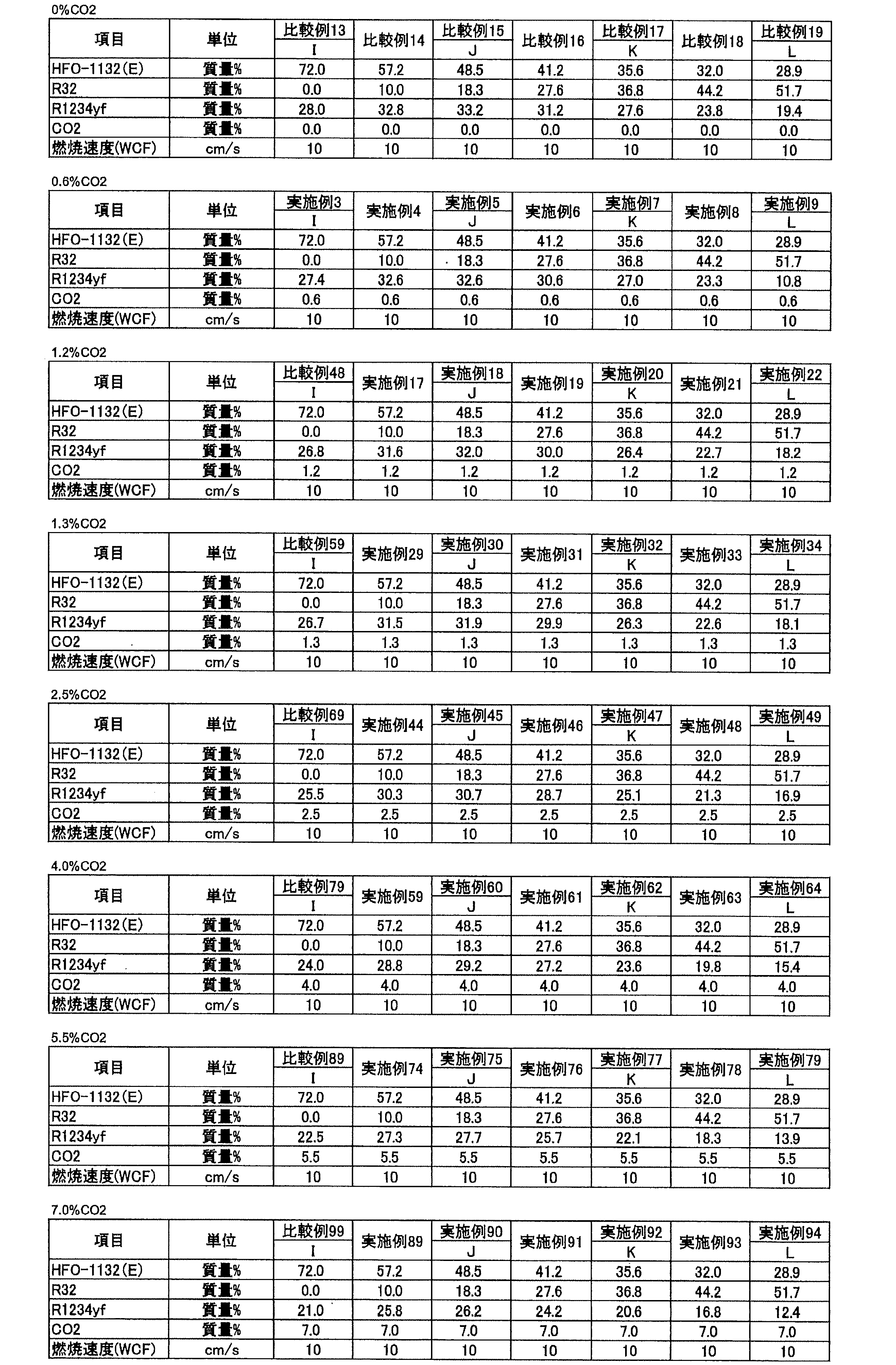
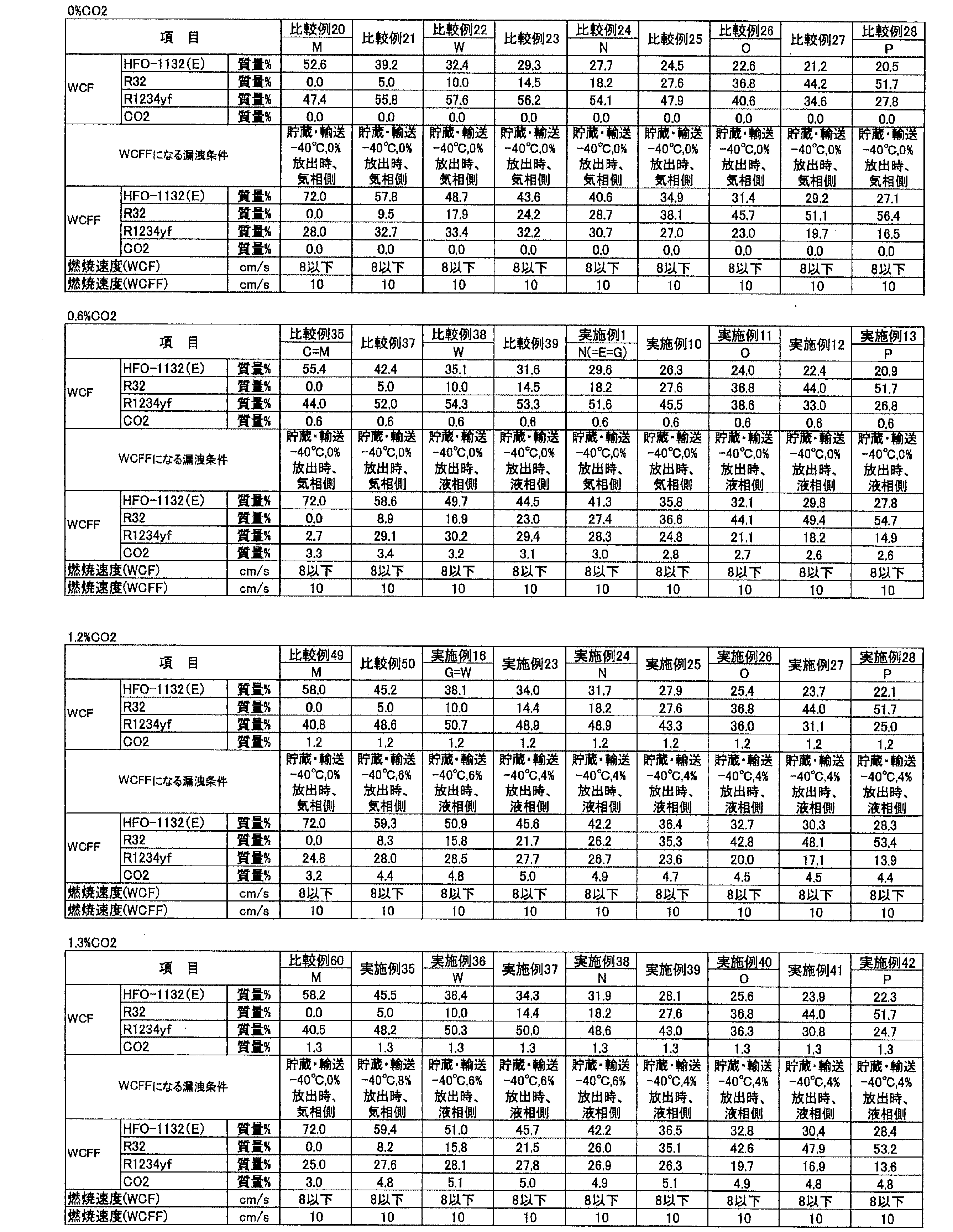
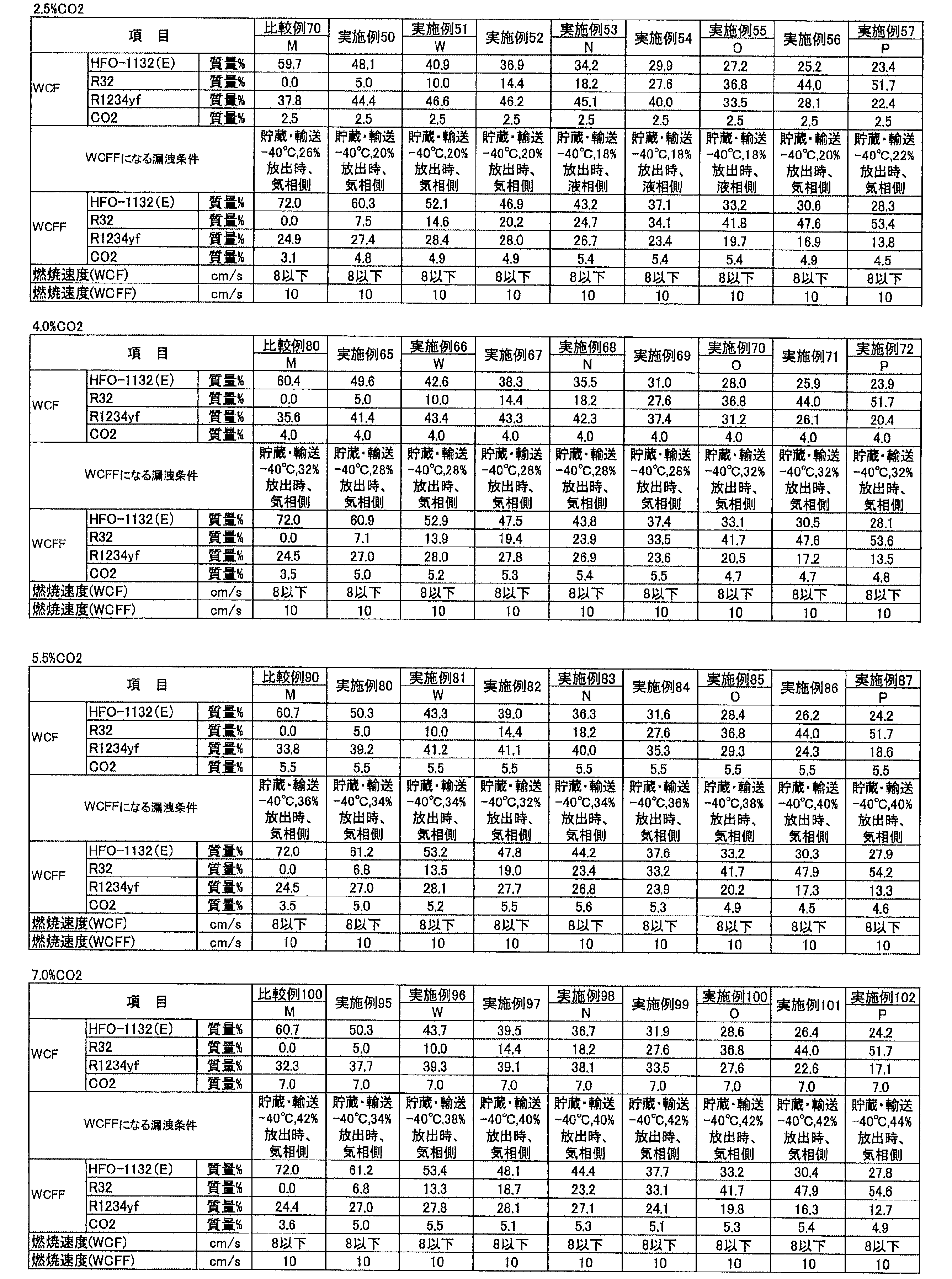
凝縮温度:45℃
過熱度:5K
過冷却度;5K
Ecomp(圧縮仕事量):0.7kWh
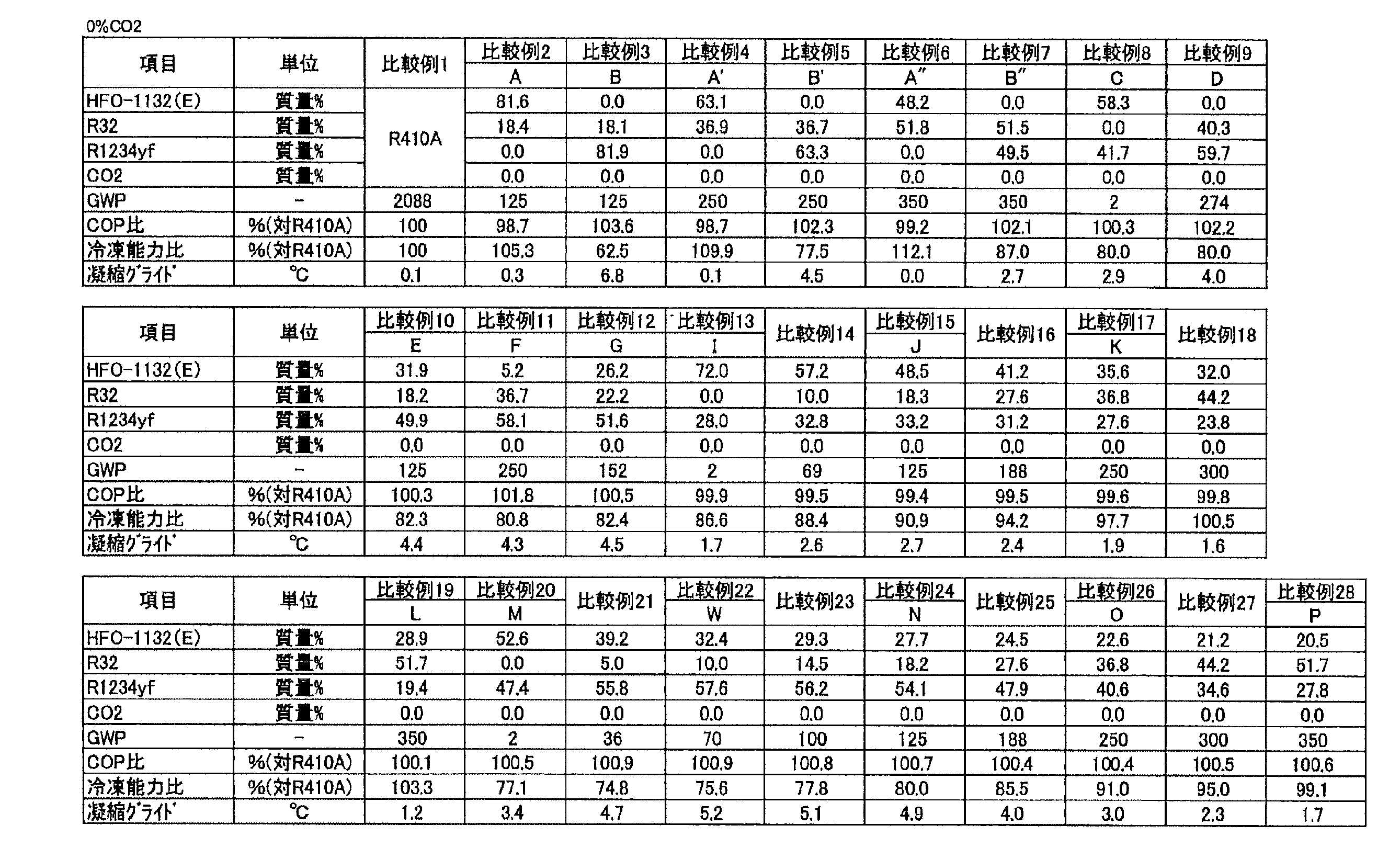
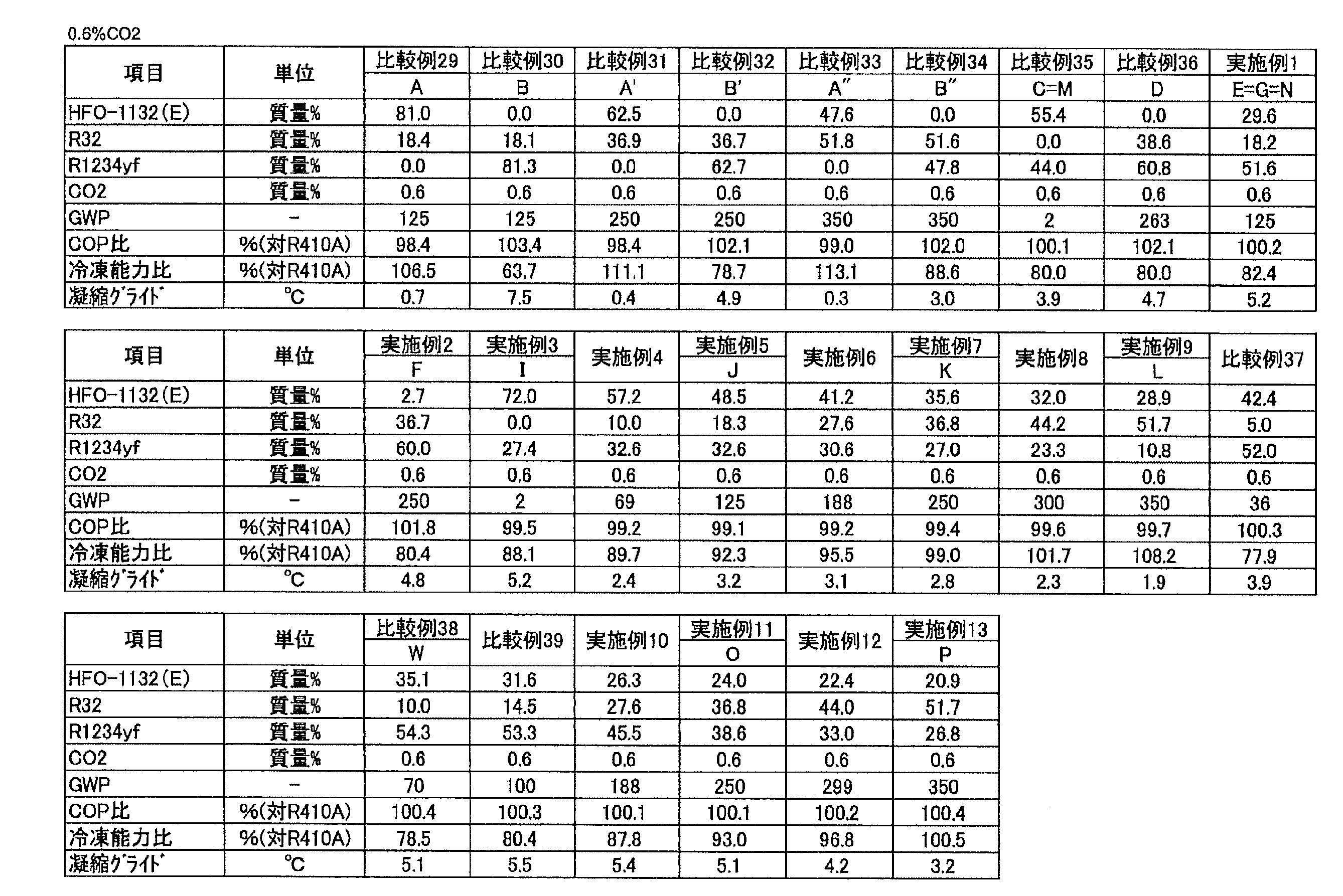
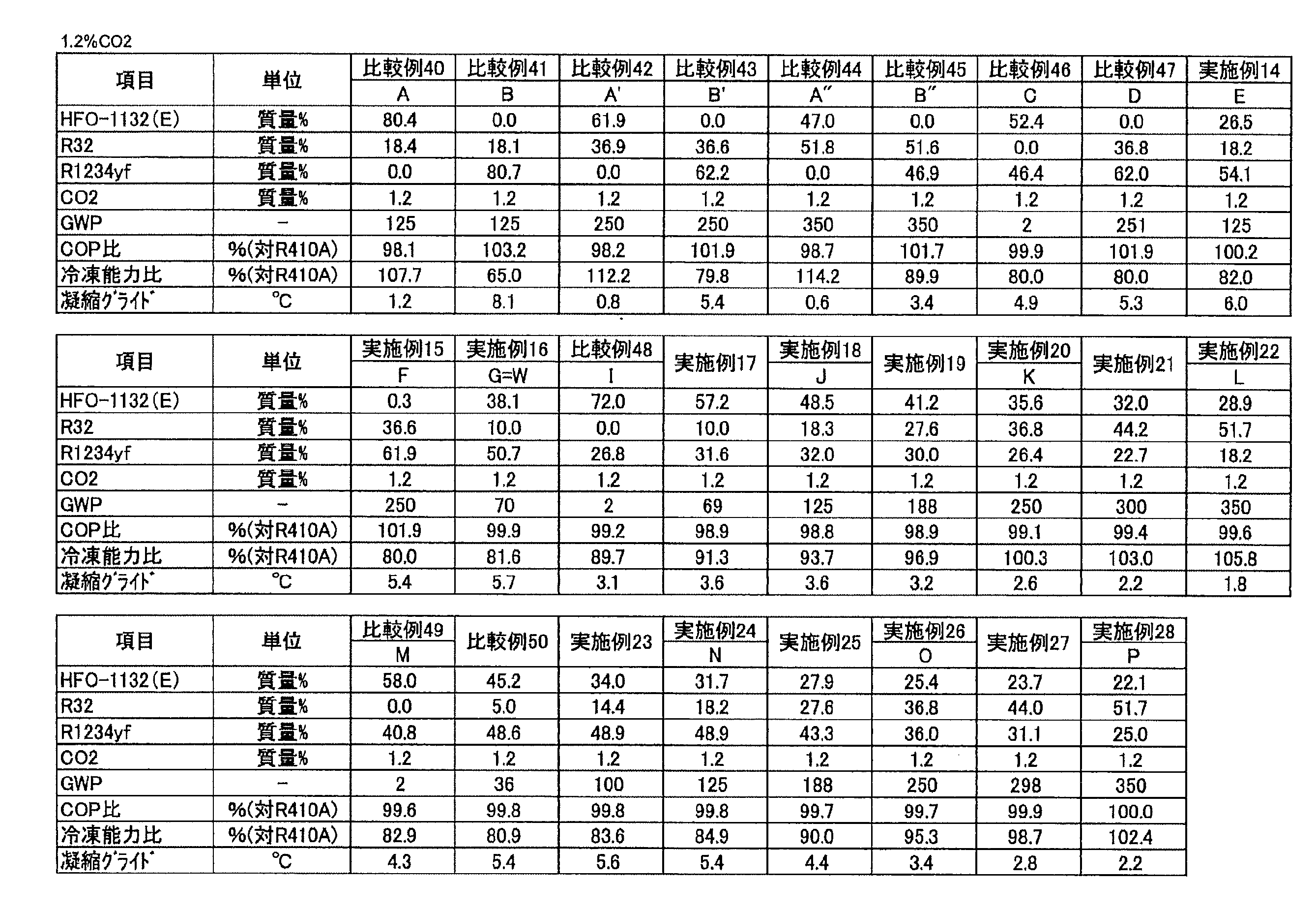
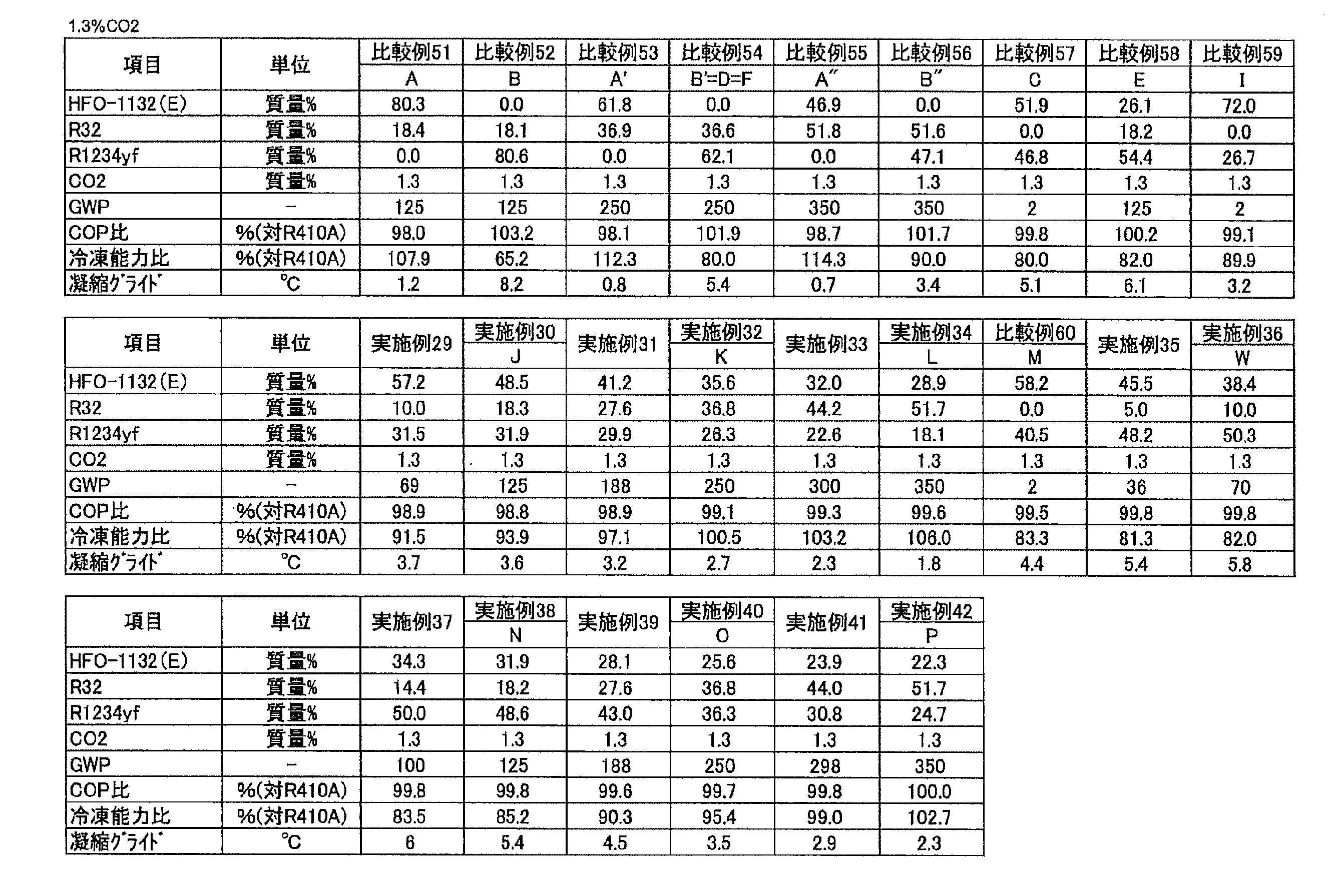
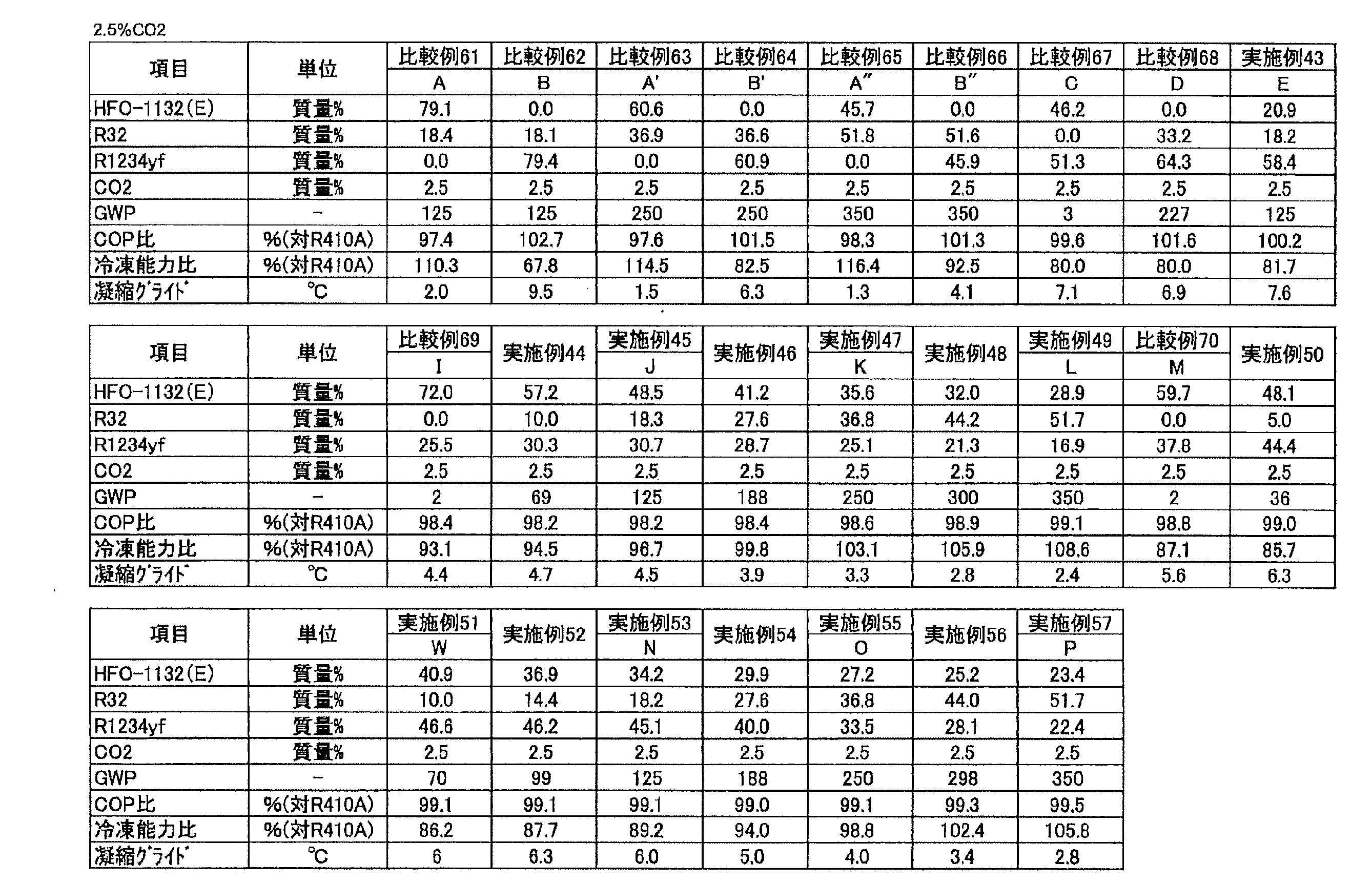
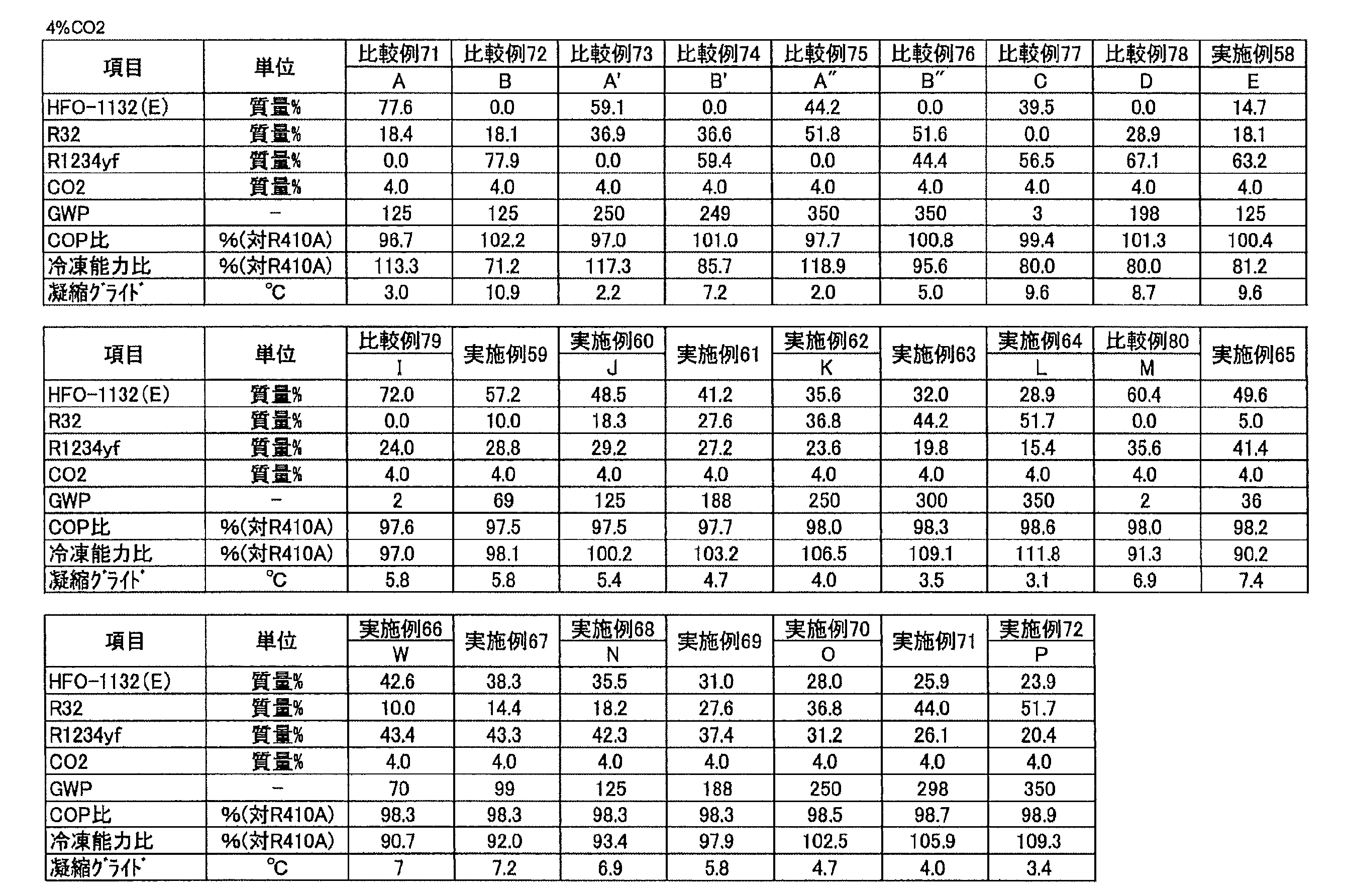
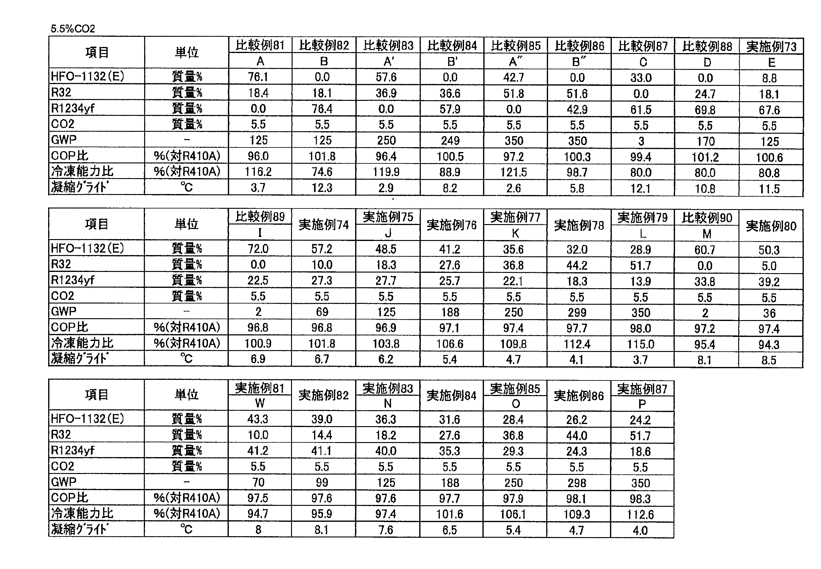
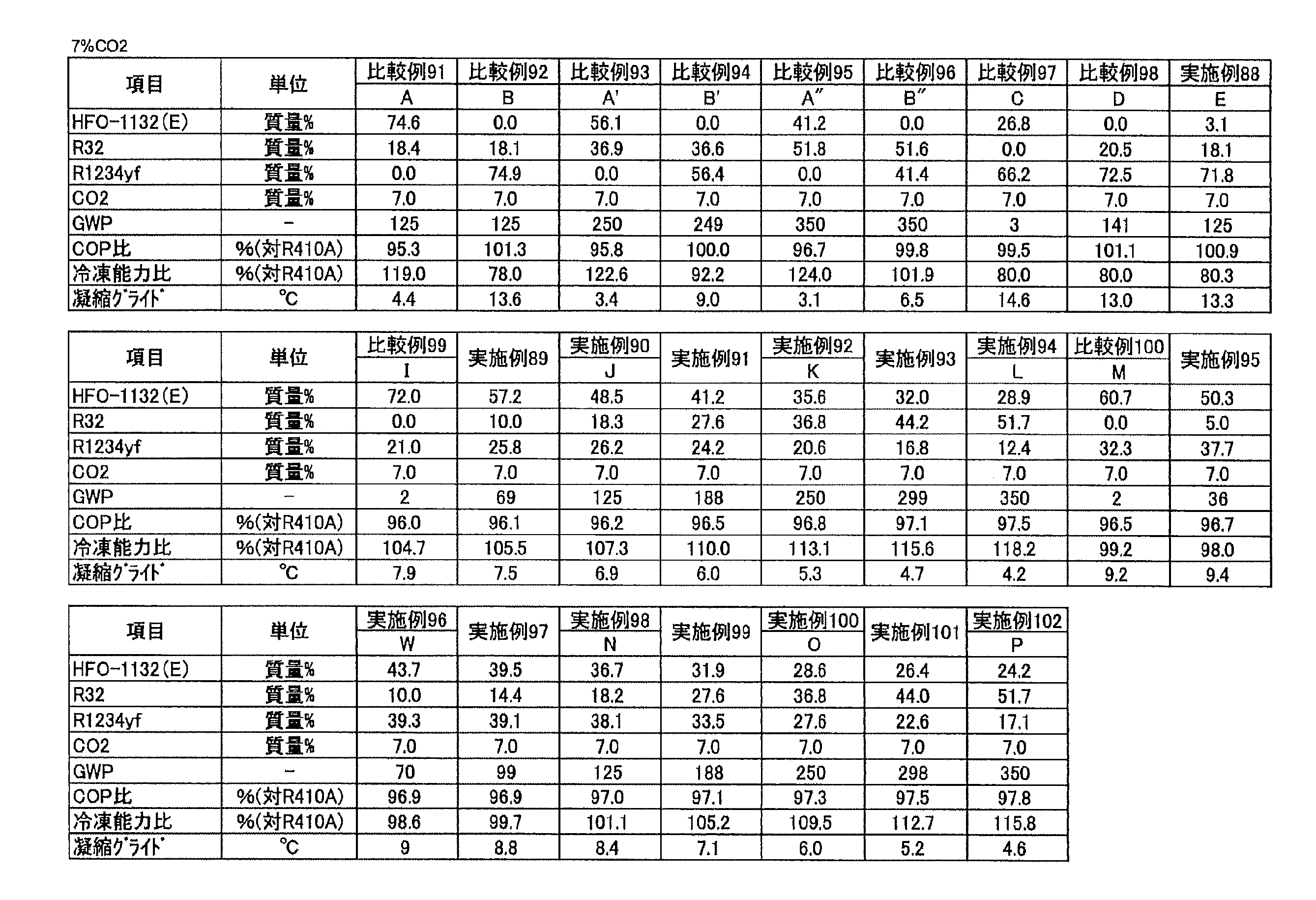

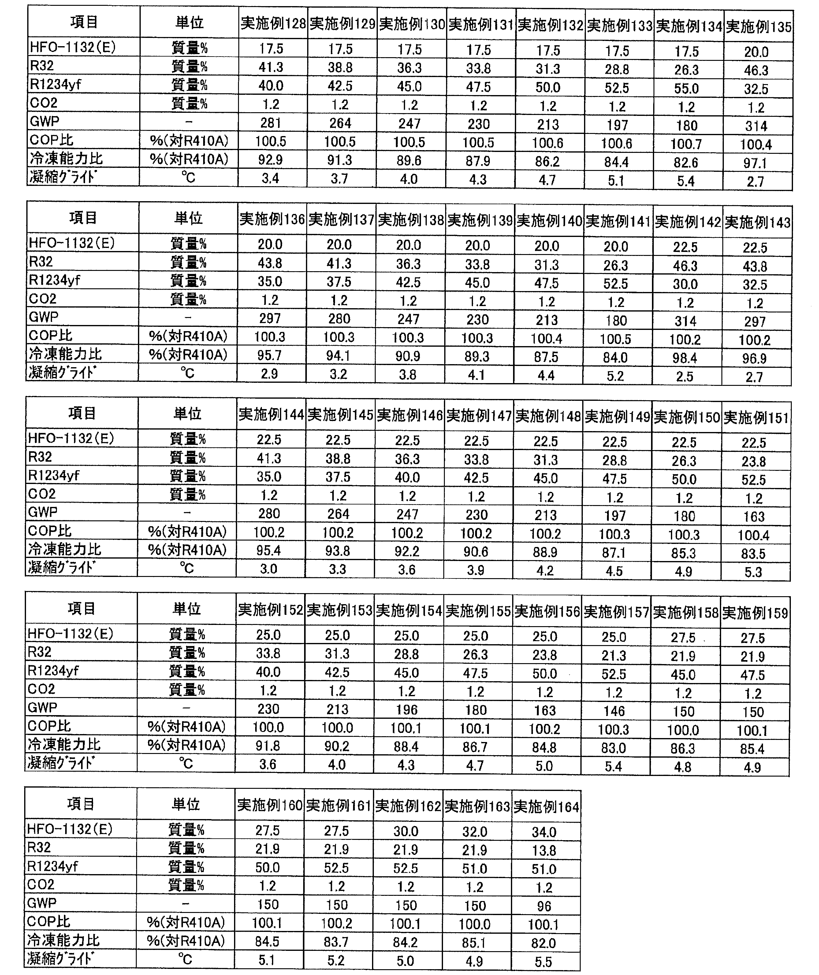
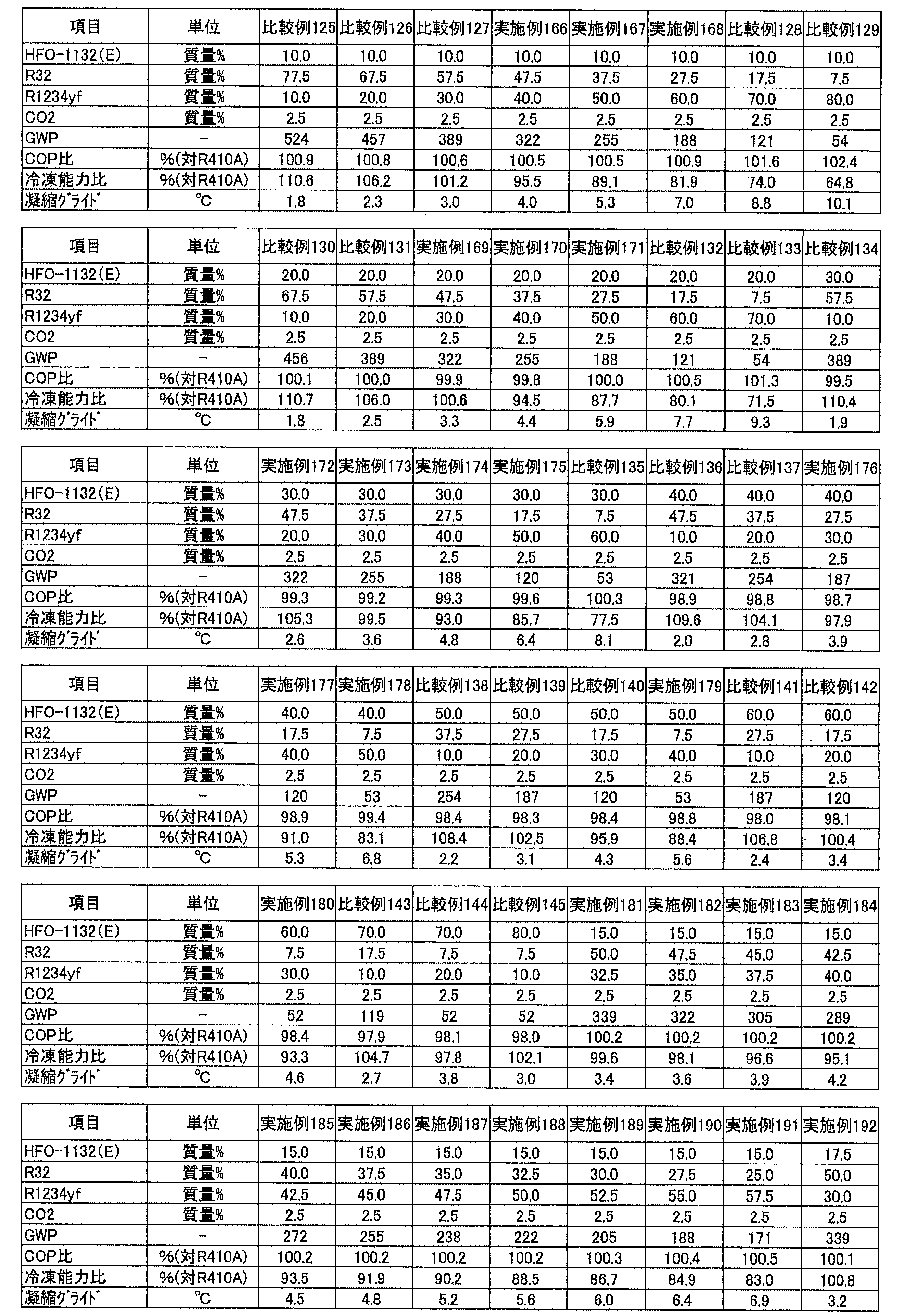
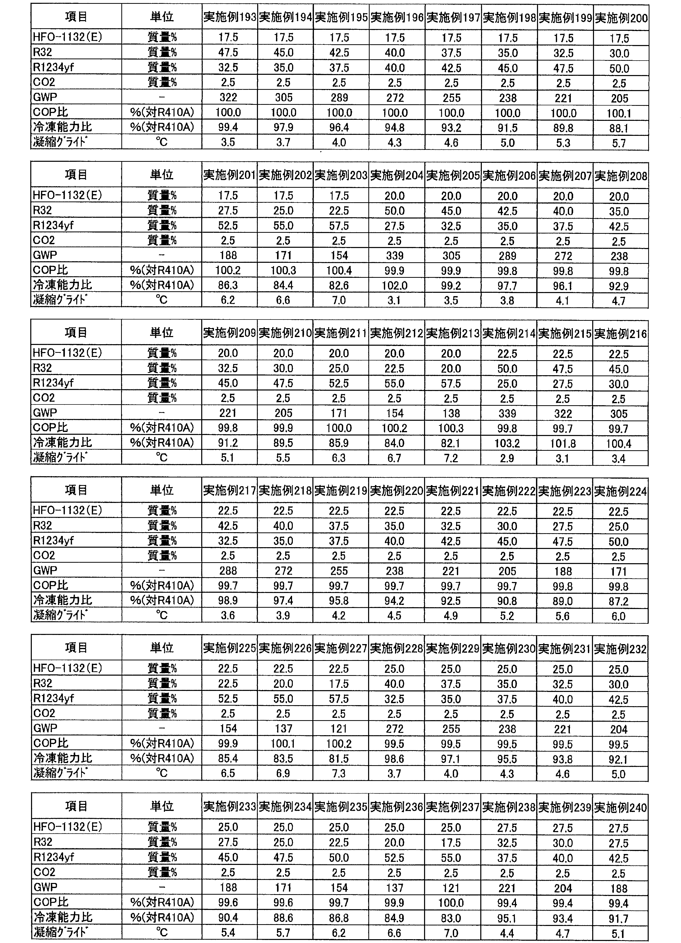
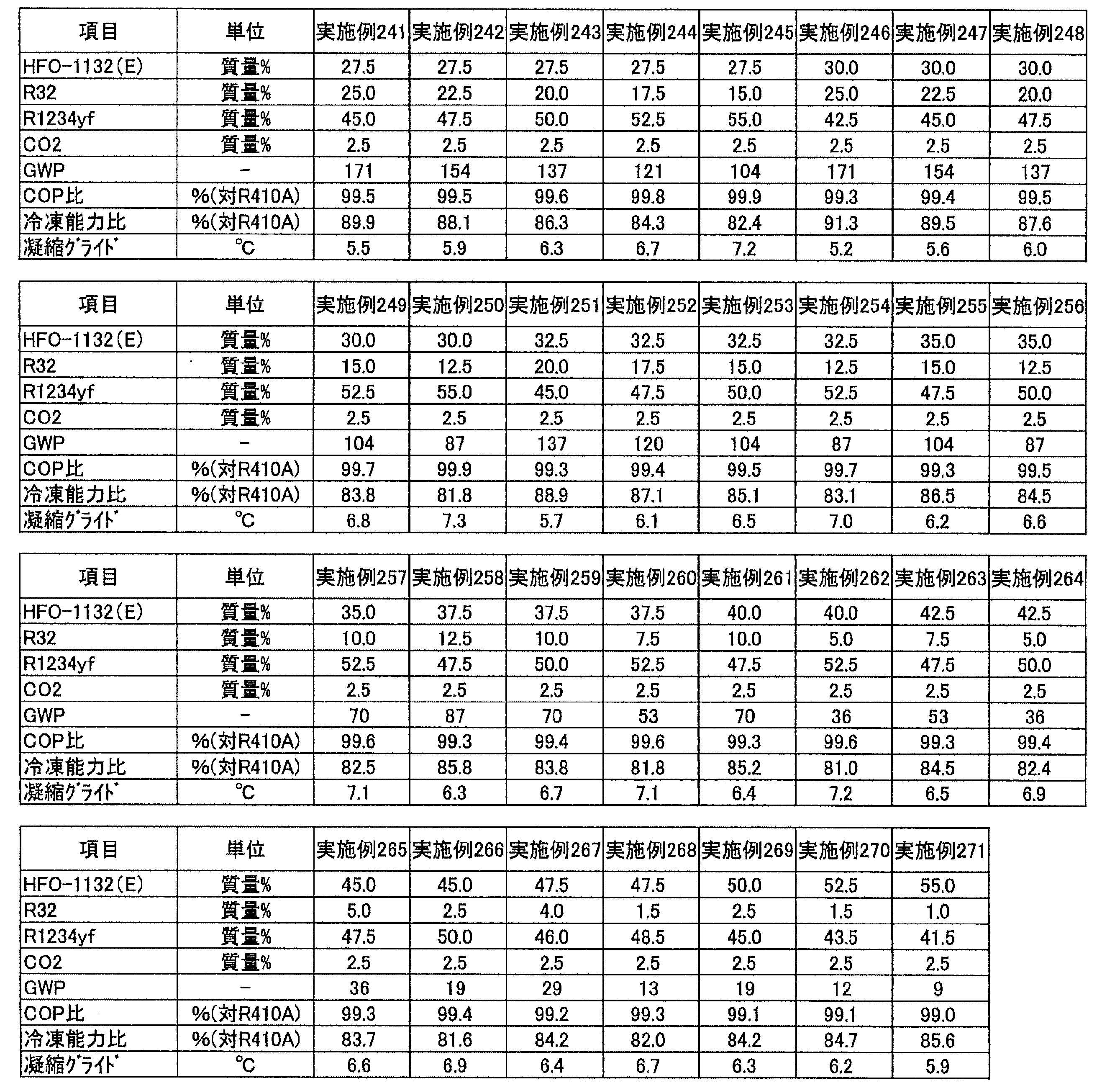
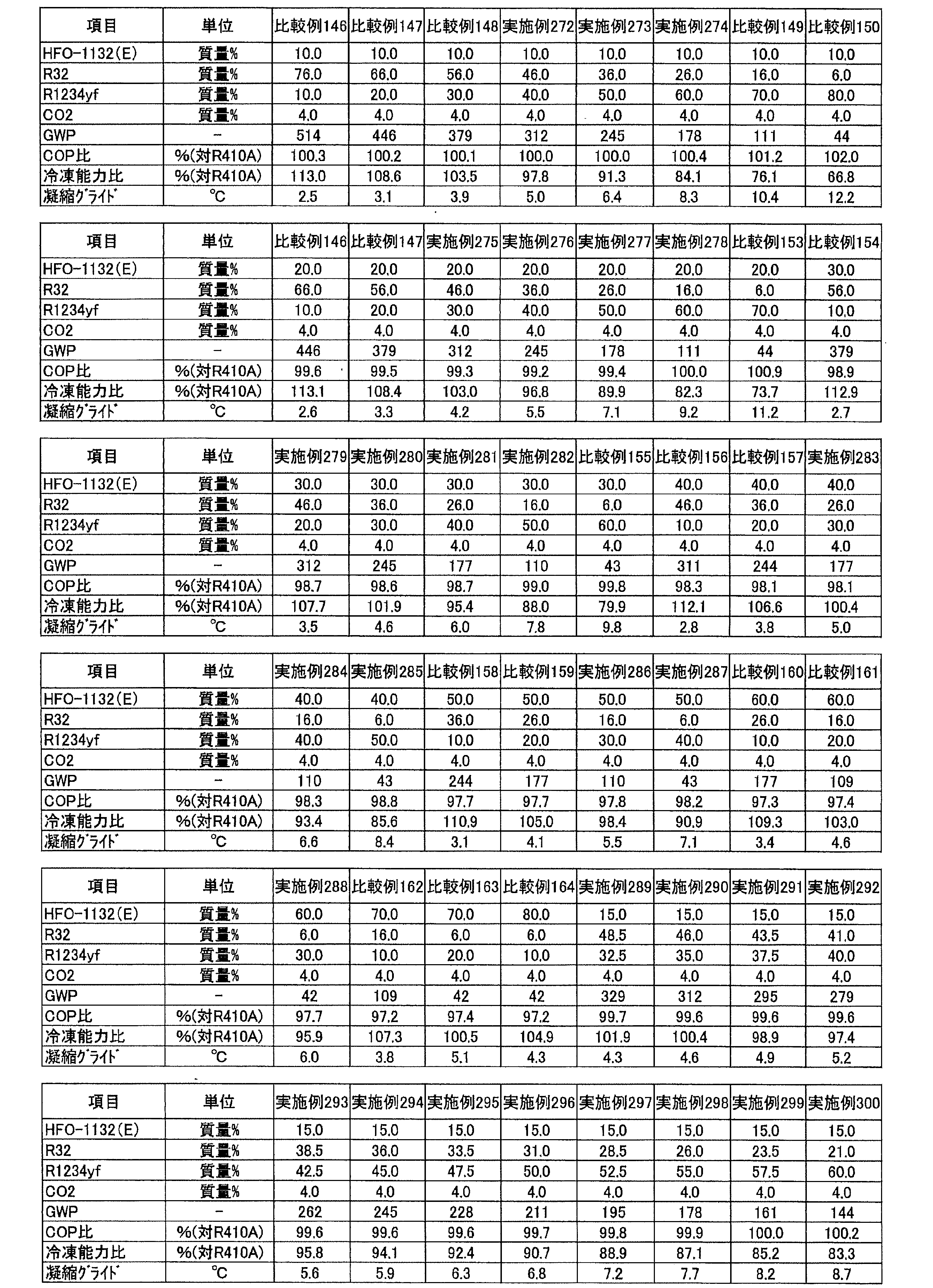
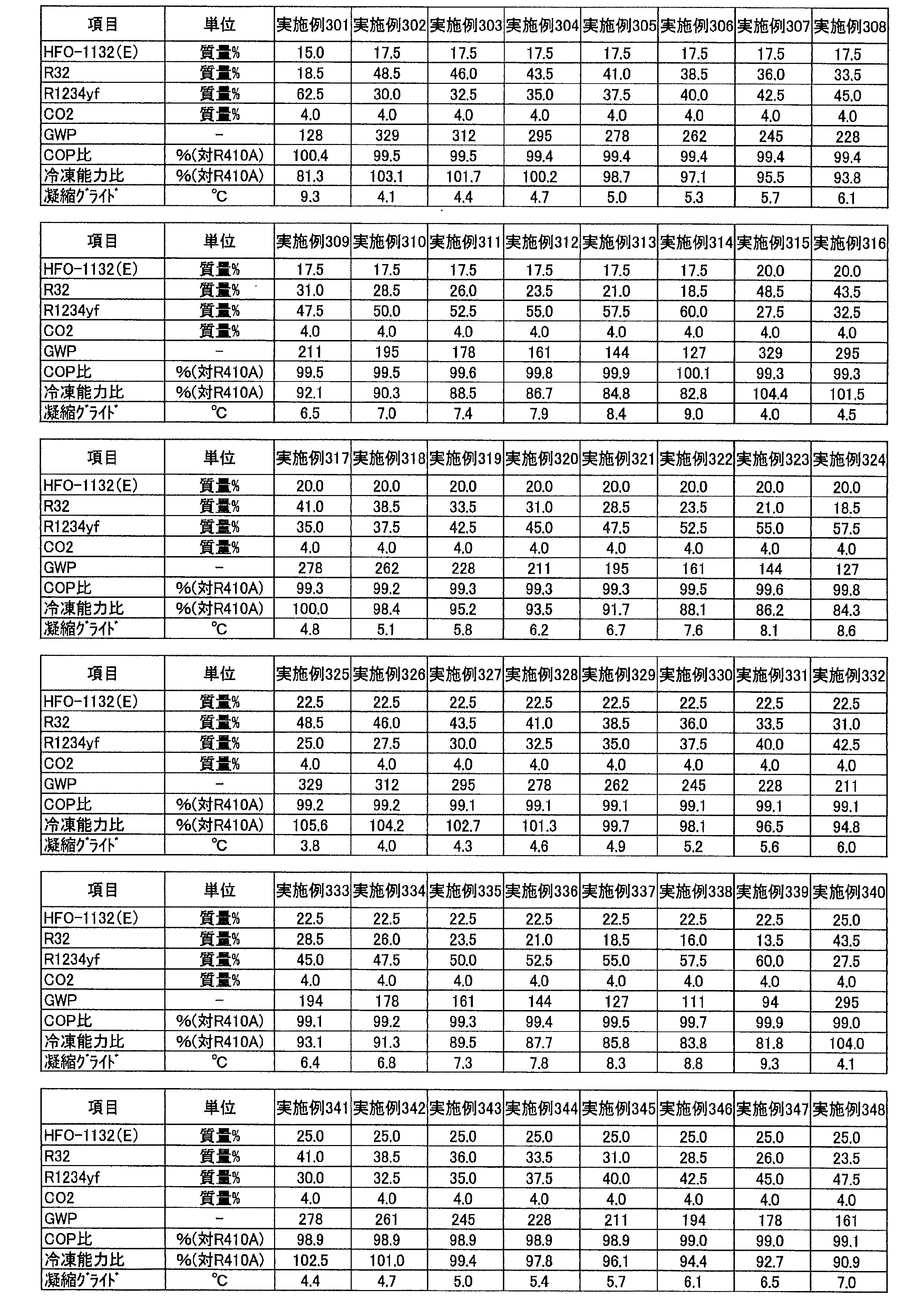

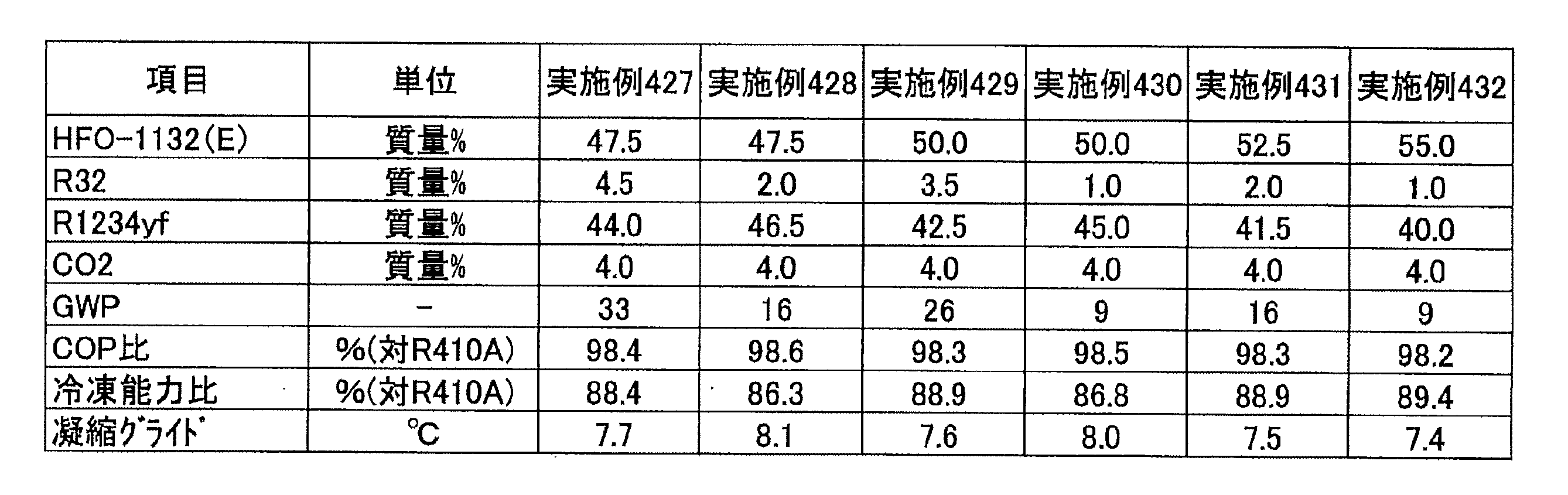
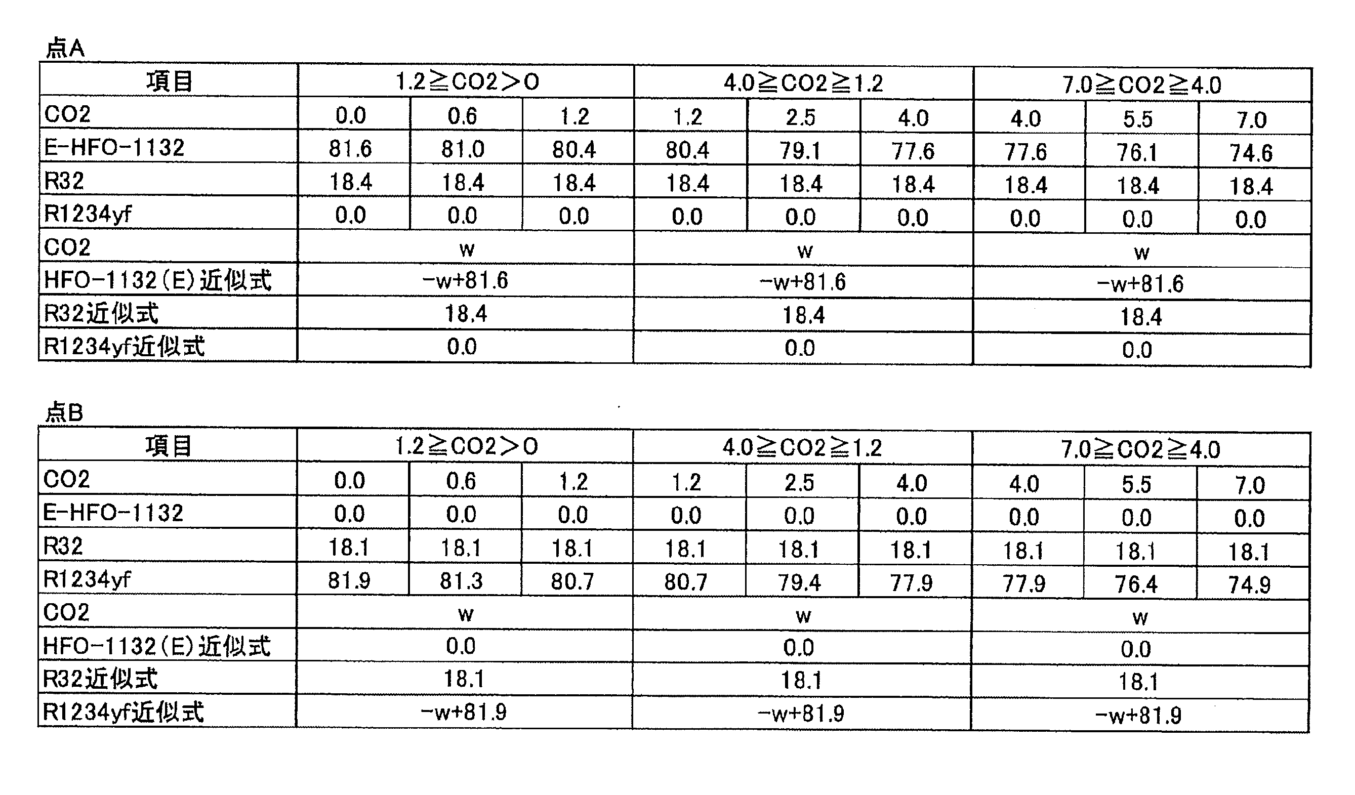
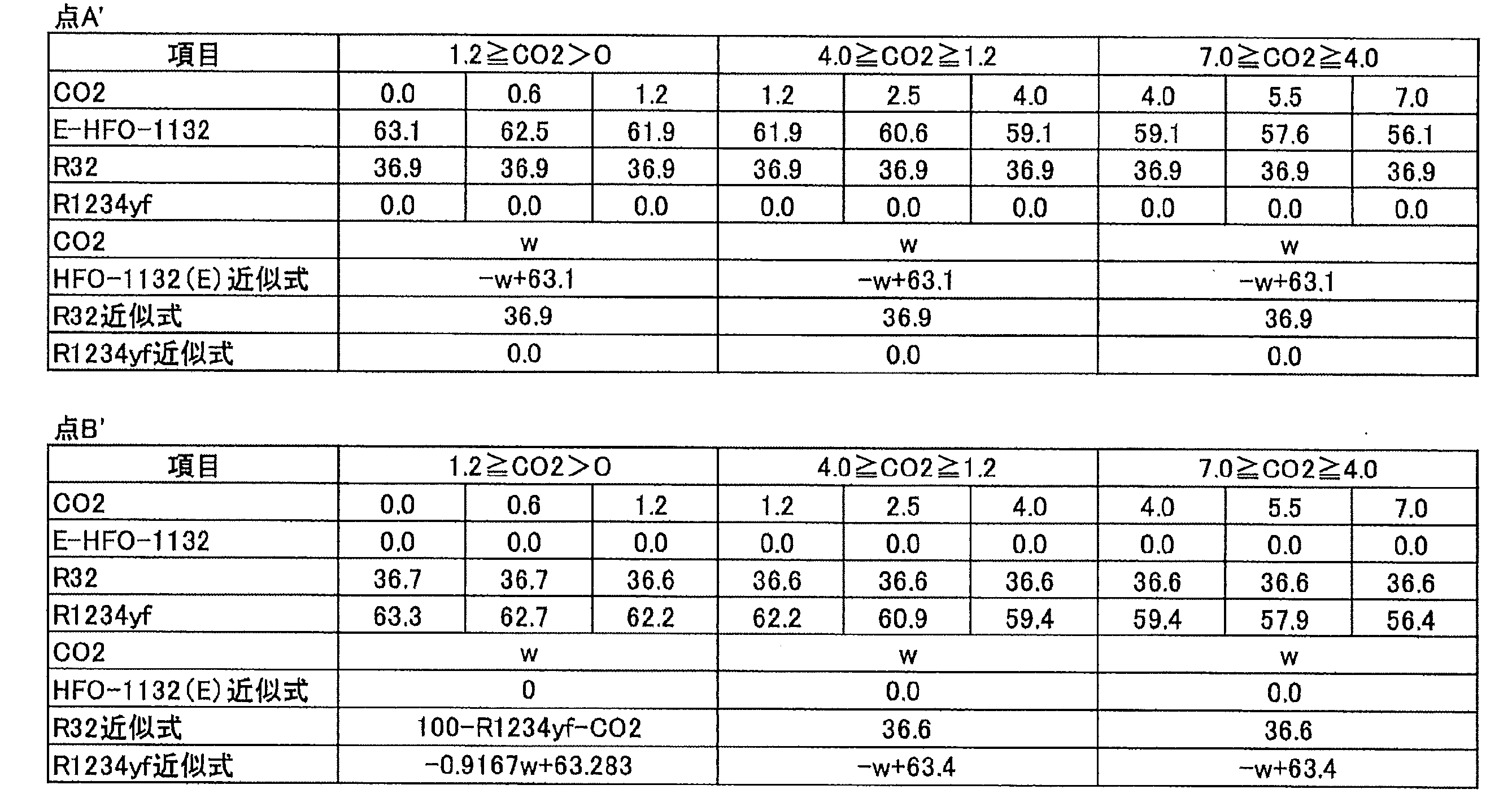
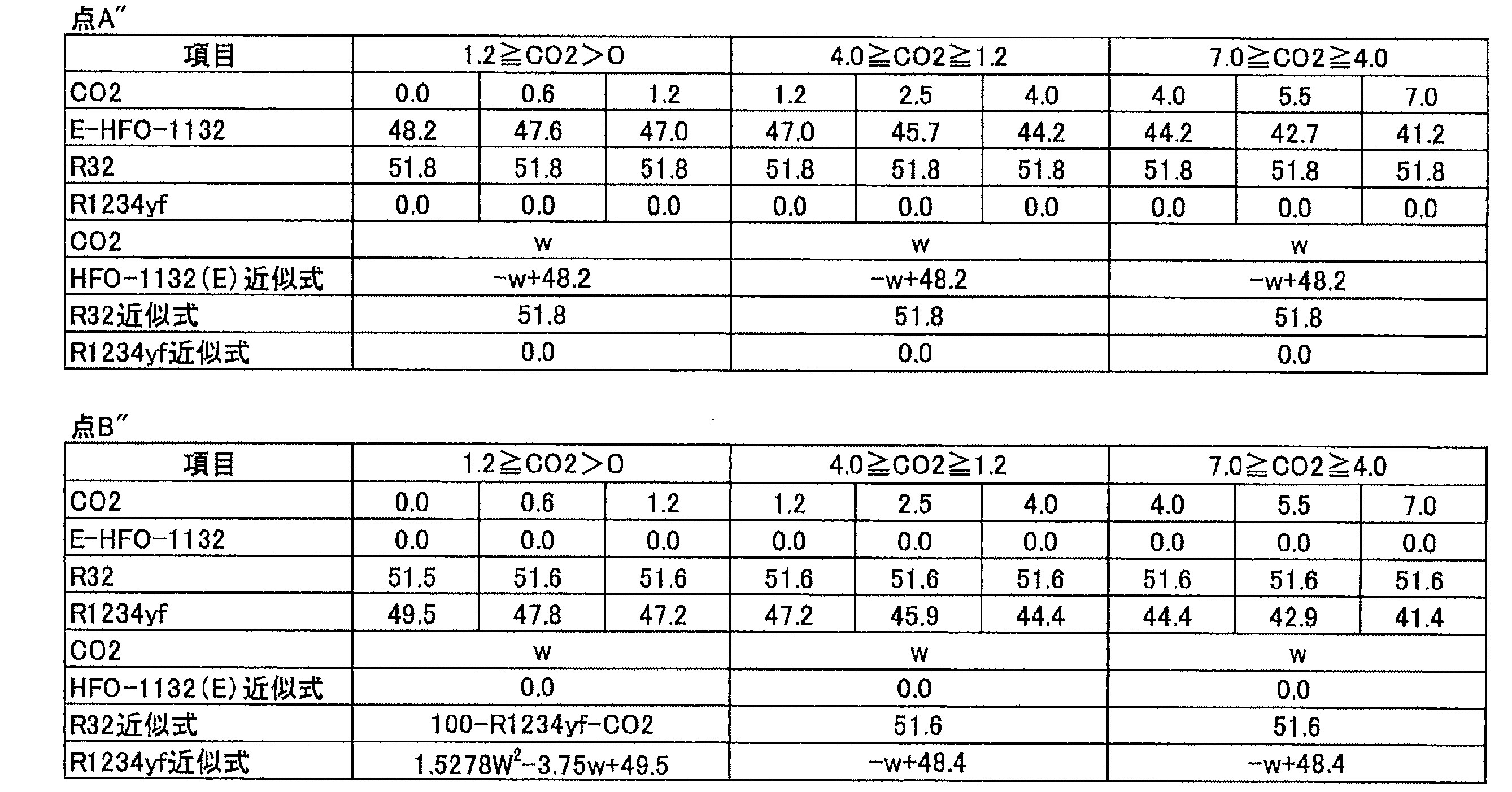
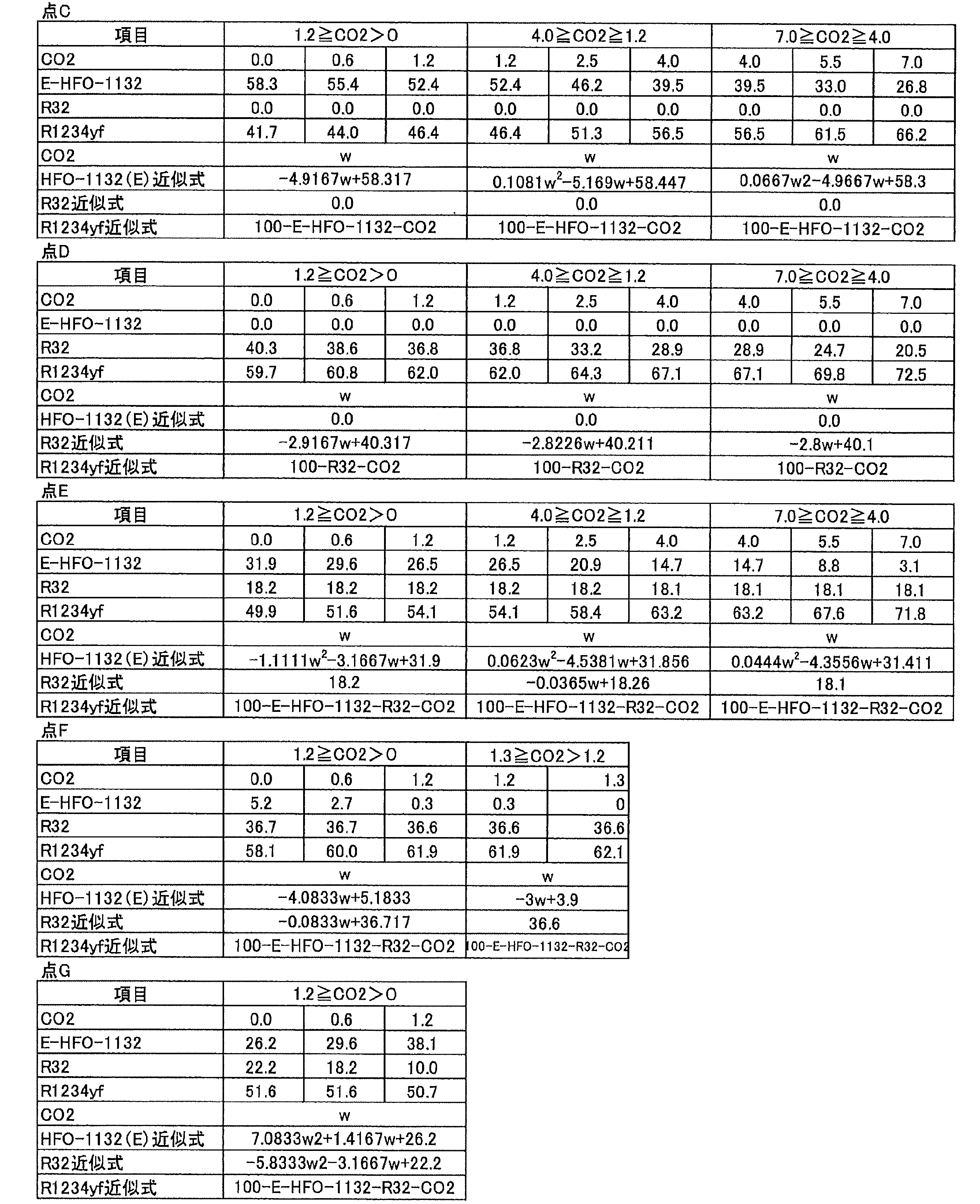
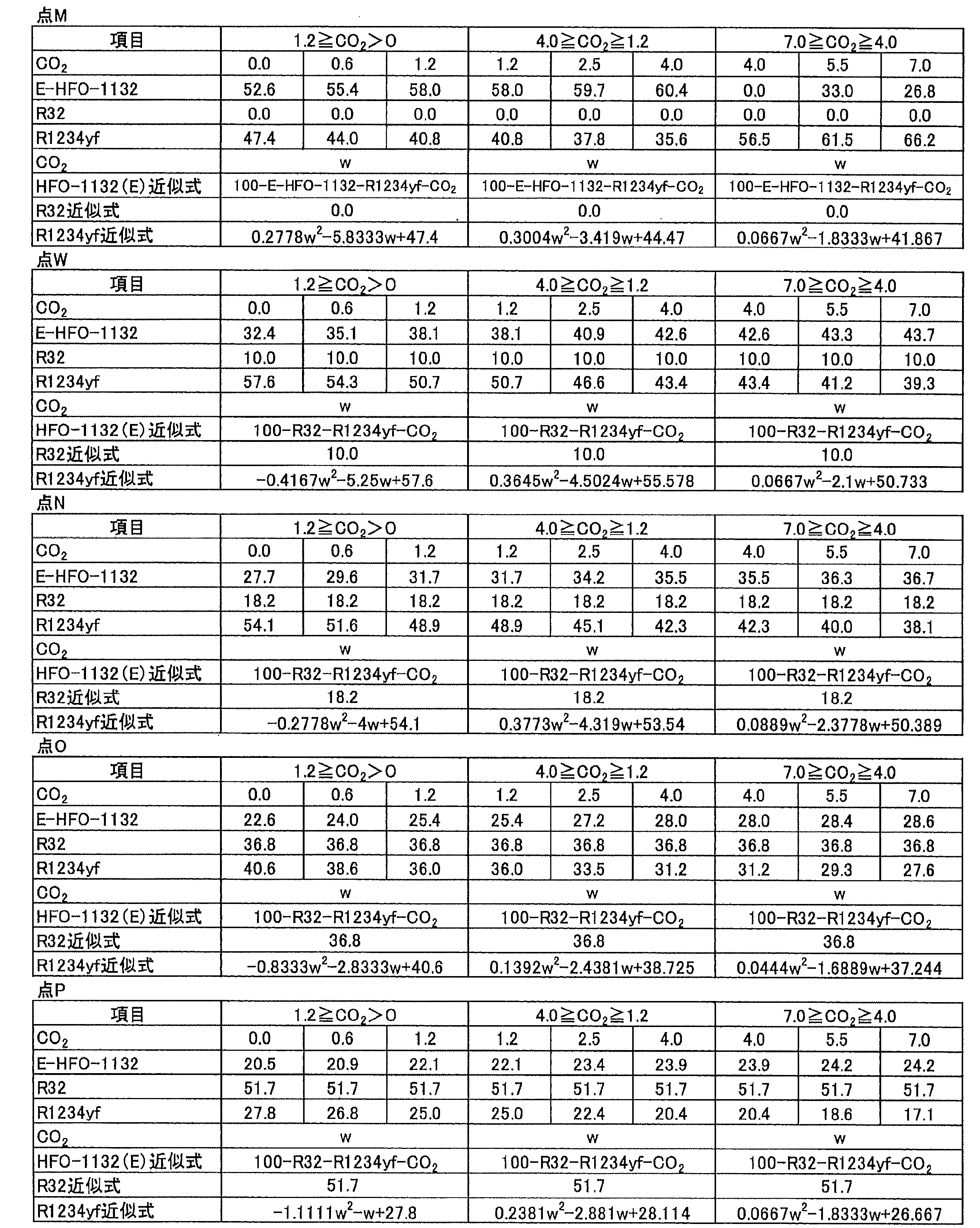
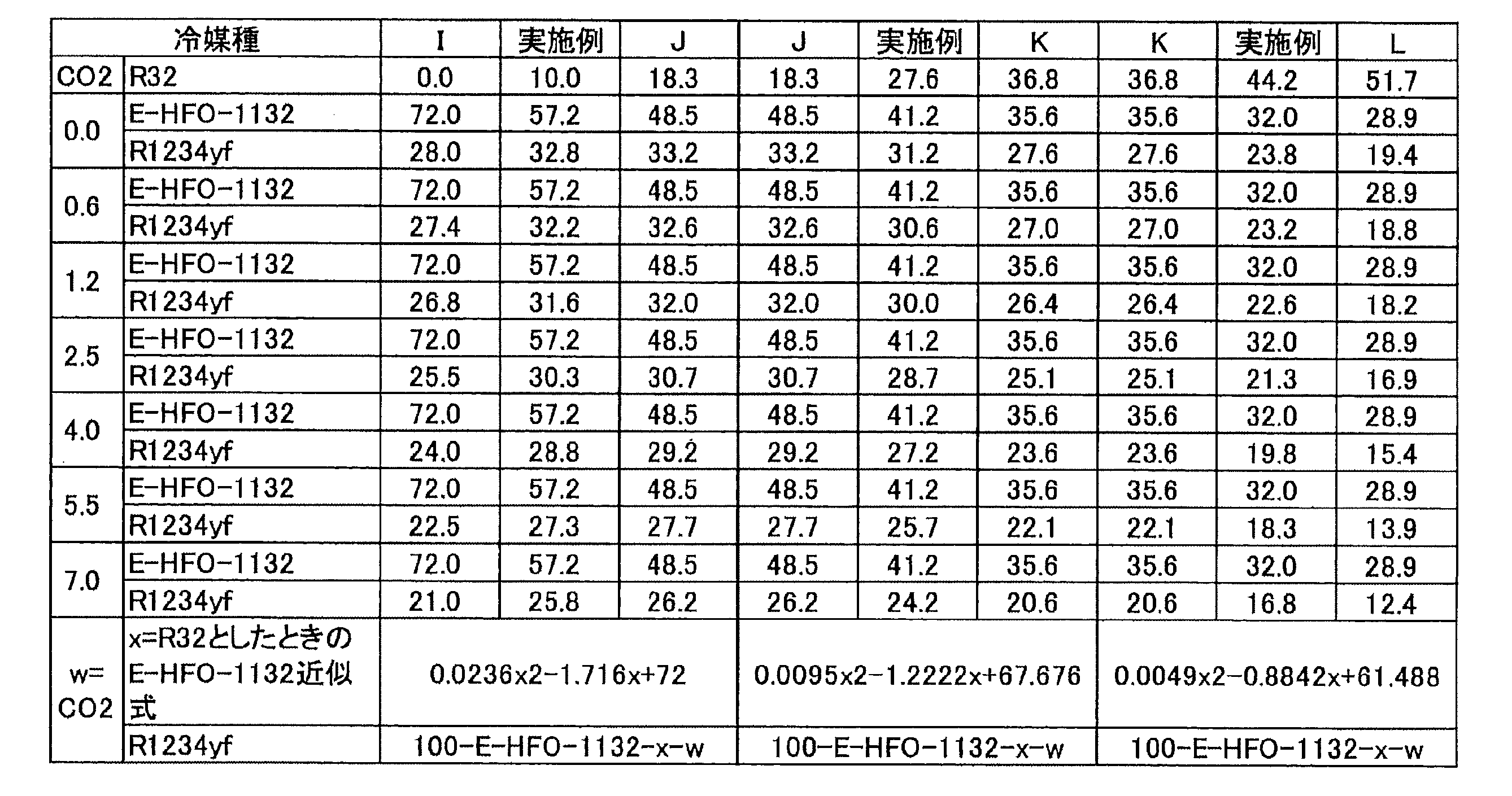
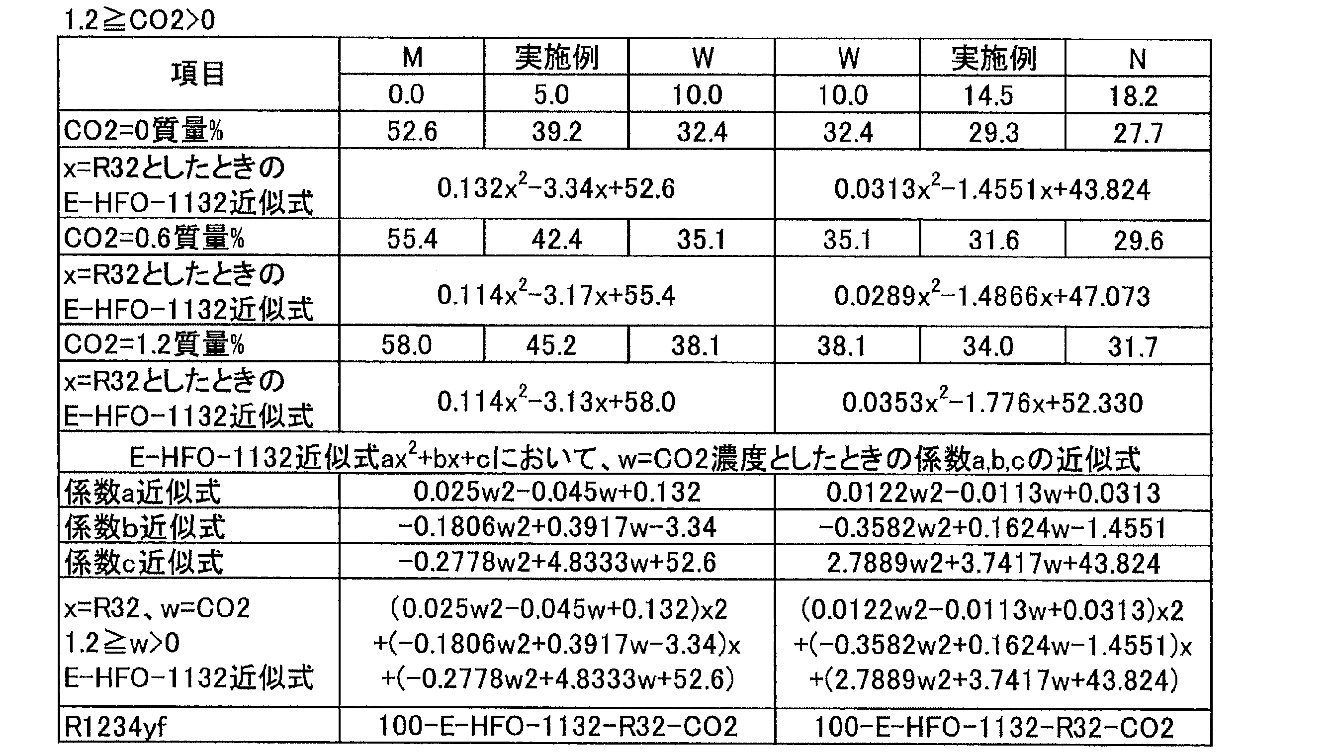

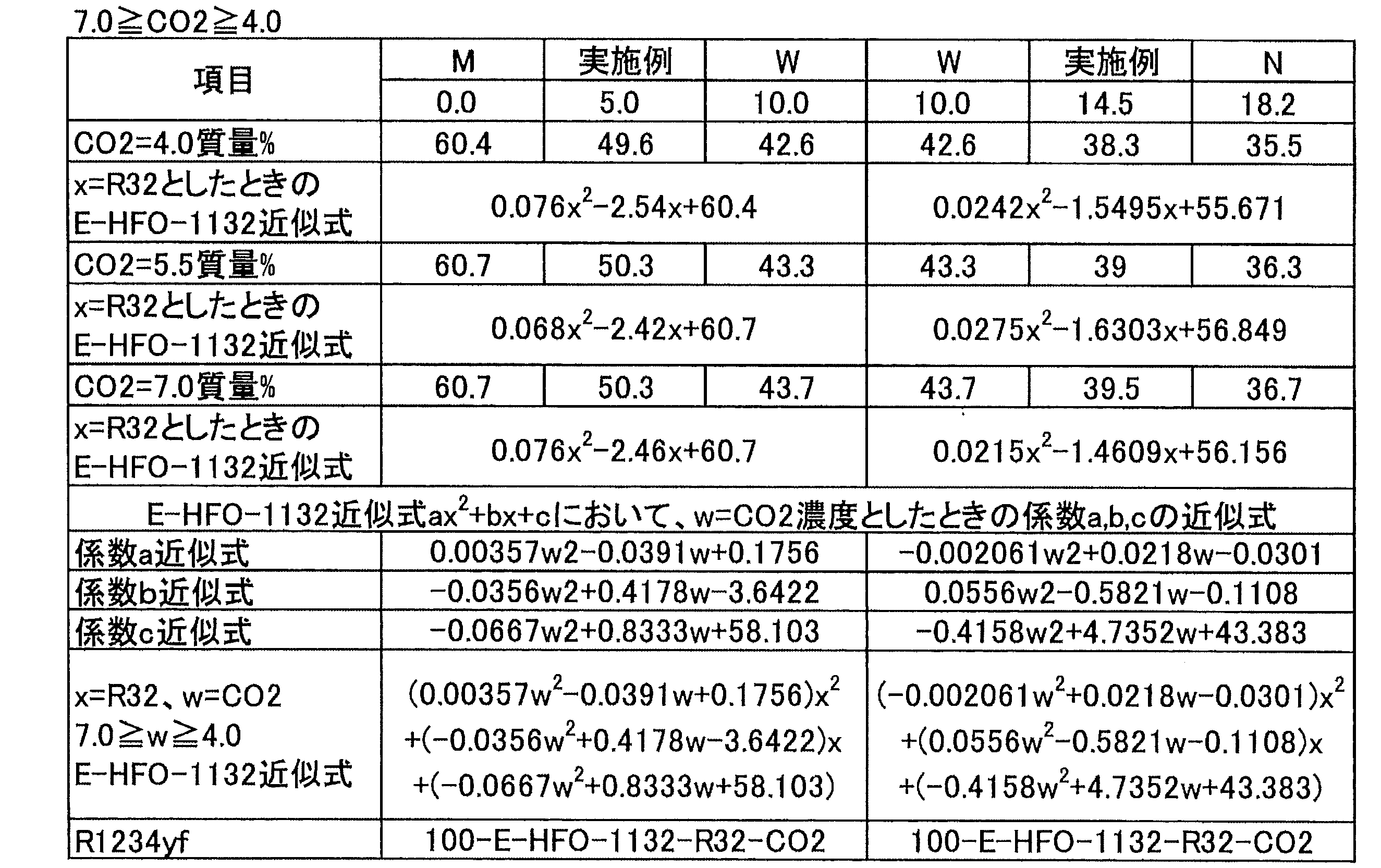
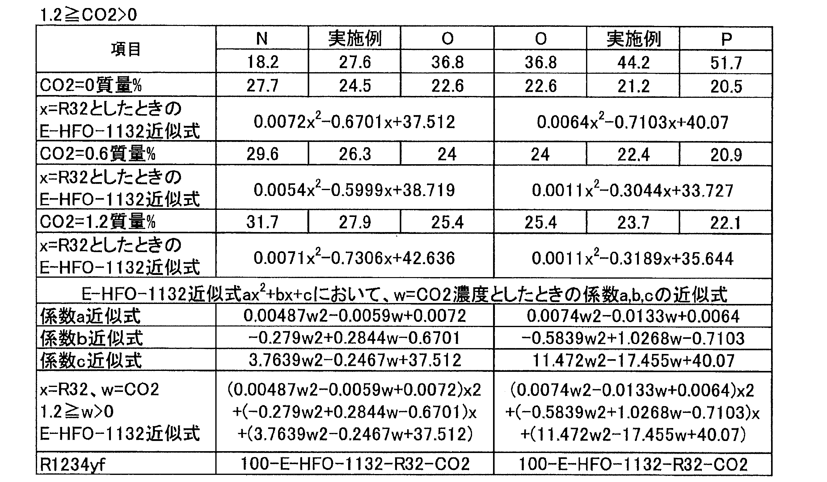

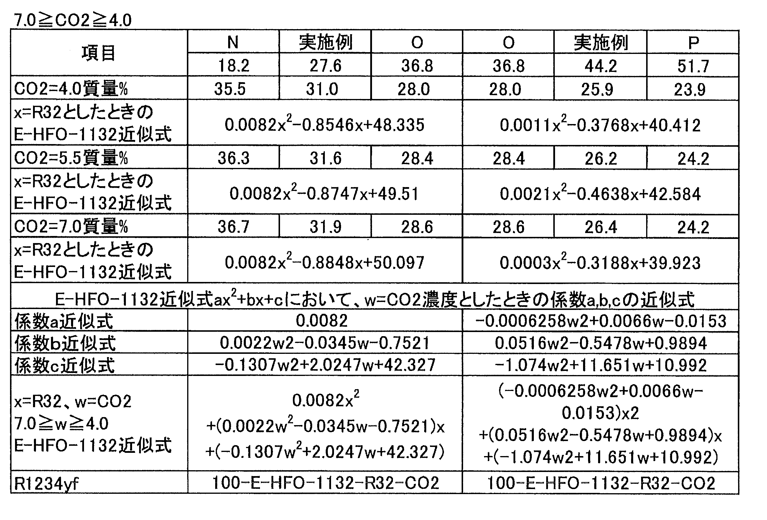
以下、本開示において用いられる冷媒である冷媒2A~冷媒2Eについて、詳細に説明する。
冷媒2Aとしては、「冷媒2A1」及び「冷媒2A2」が挙げられる。以下、冷媒2A1及び冷媒2A2についてそれぞれ説明する。本開示において、冷媒2A1及び冷媒2A2は、それぞれ混合冷媒である。
冷媒2A1は、HFO-1132(E)、HFC-32及びHFO-1234yfを必須成分として含有する混合冷媒である。以下、本項目において、HFO-1132(E)、HFC-32及びHFO-1234yfを「三成分」とも称する。
点A(HFO-1132(E)/HFC-32/HFO-1234yf=51.8/1.0/47.2質量%)、
点B(HFO-1132(E)/HFC-32/HFO-1234yf=35.3/1.0/63.7質量%)、
点C(HFO-1132(E)/HFC-32/HFO-1234yf=10.1/18.0/71.9質量%)及び
点D(HFO-1132(E)/HFC-32/HFO-1234yf=27.8/18.0/54.2質量%)、
の4点を通る図形で囲まれた領域の範囲内にある。
点A(HFO-1132(E)/HFC-32/HFO-1234yf=51.8/1.0/47.2質量%)、
点B(HFO-1132(E)/HFC-32/HFO-1234yf=35.3/1.0/63.7質量%)、
点C(HFO-1132(E)/HFC-32/HFO-1234yf=10.1/18.0/71.9質量%)及び
点D(HFO-1132(E)/HFC-32/HFO-1234yf=27.8/18.0/54.2質量%)、
の4点をそれぞれ結ぶ直線a、曲線b、直線c及び曲線dで囲まれた領域の範囲内にある。
A:ANSI/ASHRAE34-2013規格に従い測定された燃焼速度が5cm/sであって、HFC-32の濃度(質量%)が1.0質量%である質量比
B:HFC-32の濃度(質量%)が1.0質量%であって、冷凍能力がR404Aに対して95%である質量比
C:冷凍能力がR404Aに対して95%であって、GWPが125である質量比
D:GWPが125であって、ANSI/ASHRAE34-2013規格に従い測定された燃焼速度が5cm/sである質量比
「ANSI/ASHRAE34-2013規格に従い測定された燃焼速度が5cm/s」とは、ANSI/ASHRAE34-2013規格でのクラス2L(微燃)に区分するための基準である燃焼速度(10cm/s)の半分の数値であり、クラス2Lに規定される冷媒の中でも比較的安全であることを意味する。具体的には、「燃焼速度(10cm/s)の半分の数値」であると、万が一着火した場合にも火炎が伝播しにくいという点で比較的安全である。なお、以下ANSI/ASHRAE34-2013規格に従い測定された燃焼速度を、単に「燃焼速度」とも称する。
また、直線aよりも三角組成図の頂点HFC-32側の領域では、予想外に冷凍能力が大きい。
y=1.0
z=100-x-y
35.3≦x≦51.8
点B及びCは、いずれも曲線b上にある。曲線bは、冷凍能力がR404Aに対して95%である質量比を示す曲線である。曲線bよりも三角組成図の頂点HFO-1132(E)側及び頂点HFC-32側の領域では、三成分の混合冷媒の冷凍能力がR404Aに対して95%を超える。
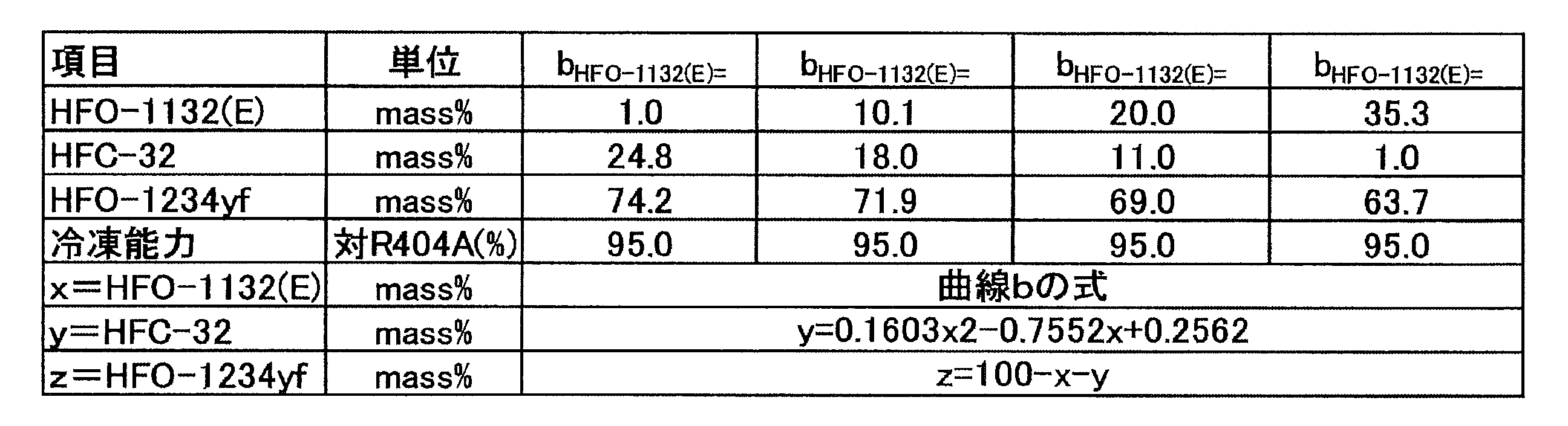
y=18.0
z=100-x-y
10.1≦x≦27.8
点A及びDは、いずれも曲線d上にある。曲線dは、燃焼速度が5cm/sになる質量比を示す曲線である。曲線dよりも三角組成図の頂点HFO-1234yf側の領域では、三成分の混合冷媒は、燃焼速度が5.0cm/s未満である。
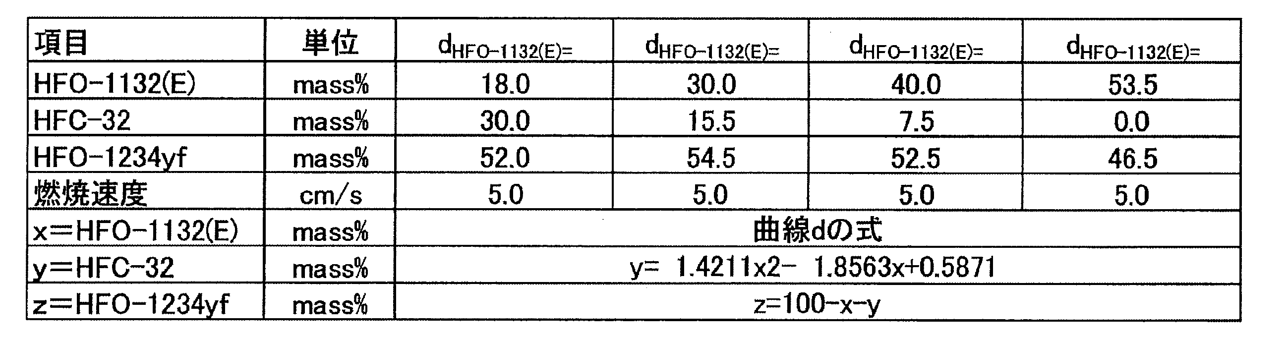
点A(HFO-1132(E)/HFC-32/HFO-1234yf=51.8/1.0/47.2質量%)、
点B(HFO-1132(E)/HFC-32/HFO-1234yf=35.3/1.0/63.7質量%)、
点E(HFO-1132(E)/HFC-32/HFO-1234yf=15.2/14.3/70.5質量%)及び
点F(HFO-1132(E)/HFC-32/HFO-1234yf=31.1/14.3/54.6質量%)、
の4点を通る図形で囲まれた領域の範囲内にあることが好ましい。
点A(HFO-1132(E)/HFC-32/HFO-1234yf=51.8/1.0/47.2質量%)、
点B(HFO-1132(E)/HFC-32/HFO-1234yf=35.3/1.0/63.7質量%)、
点E(HFO-1132(E)/HFC-32/HFO-1234yf=15.2/14.3/70.5質量%)及び
点F(HFO-1132(E)/HFC-32/HFO-1234yf=31.1/14.3/54.6質量%)
の4点をそれぞれ結ぶ直線a、曲線b、直線e及び曲線dで囲まれた領域の範囲内にあることが好ましい。
E:冷凍能力がR404Aに対して95%であって、GWPが100である質量比
F:GWPが100であって、ANSI/ASHRAE34-2013規格に従い測定された燃焼速度が5cm/sである、GWP=100の質量比
直線a及び曲線bについては、上記の通りである。点Eは曲線b上にある。
y=14.3
z=100-x-y
15.2≦x≦31.1
点A及びFは、いずれも曲線d上にある。曲線dについては、上記の通りである。
点A(HFO-1132(E)/HFC-32/HFO-1234yf=51.8/1.0/47.2質量%)、
点B(HFO-1132(E)/HFC-32/HFO-1234yf=35.3/1.0/63.7質量%)、
点C(HFO-1132(E)/HFC-32/HFO-1234yf=10.1/18.0/71.9質量%)及び
点D(HFO-1132(E)/HFC-32/HFO-1234yf=27.8/18.0/54.2質量%)、
の4点を通る図形で囲まれた領域の範囲内にあることが好ましい。
点A(HFO-1132(E)/HFC-32/HFO-1234yf=51.8/1.0/47.2質量%)、
点B(HFO-1132(E)/HFC-32/HFO-1234yf=35.3/1.0/63.7質量%)、
点E(HFO-1132(E)/HFC-32/HFO-1234yf=15.2/14.3/70.5質量%)及び
点F(HFO-1132(E)/HFC-32/HFO-1234yf=31.1/14.3/54.6質量%)、
の4点を通る図形で囲まれた領域の範囲内にあることがより好ましい。
冷媒2A2は、HFO-1132(E)、HFC-32及びHFO-1234yfを必須成分として含有する混合冷媒である。以下、本項目において、HFO-1132(E)、HFC-32及びHFO-1234yfを「三成分」とも称する。
点P(HFO-1132(E)/HFC-32/HFO-1234yf=45.6/1.0/53.4質量%)、
点B(HFO-1132(E)/HFC-32/HFO-1234yf=35.3/1.0/63.7質量%)、
点Q(HFO-1132(E)/HFC-32/HFO-1234yf=1.0/24.8/74.2質量%)、
点R(HFO-1132(E)/HFC-32/HFO-1234yf=1.0/29.2/69.8質量%)及び
点S(HFO-1132(E)/HFC-32/HFO-1234yf=6.5/29.2/64.3質量%)、
の5点を通る図形で囲まれた領域の範囲内にある、組成物。
点P(HFO-1132(E)/HFC-32/HFO-1234yf=45.6/1.0/53.4質量%)、
点B(HFO-1132(E)/HFC-32/HFO-1234yf=35.3/1.0/63.7質量%)、
点Q(HFO-1132(E)/HFC-32/HFO-1234yf=1.0/24.8/74.2質量%)、
点R(HFO-1132(E)/HFC-32/HFO-1234yf=1.0/29.2/69.8質量%)及び
点S(HFO-1132(E)/HFC-32/HFO-1234yf=6.5/29.2/64.3質量%)、
の5点をそれぞれ結ぶ直線p、曲線q、直線r、直線s及び曲線tで囲まれた領域の範囲内にある。
P:40℃での圧力が1.85MPaであって、HFC-32の濃度(質量%)が1.0質量%である質量比
B:HFC-32の濃度(質量%)が1.0質量%であって、冷凍能力がR404Aに対して95%である質量比
Q:冷凍能力がR404Aに対して95%であって、HFO-1132(E)の濃度(質量%)が1.0質量%である質量比
R:HFO-1132(E)の濃度(質量%)が1.0質量%であって、GWPが200である質量比
S:GWPが200であって、40℃での圧力が1.85MPaである質量比
「40℃での圧力が1.85MPaになる質量比」とは、温度40(℃)での飽和圧力が1.85MPaである質量比を意味する。
y=1.0
z=100-x-y
35.3≦x≦45.6
点B及びQは、いずれも曲線q上にある。曲線qは、冷凍能力がR404Aに対して95%になる質量比を示す曲線である。曲線qよりも三角組成図の頂点HFO-1132(E)側及び頂点HFC-32側の領域では、三成分の混合冷媒の冷凍能力がR404Aに対して95%を超える。
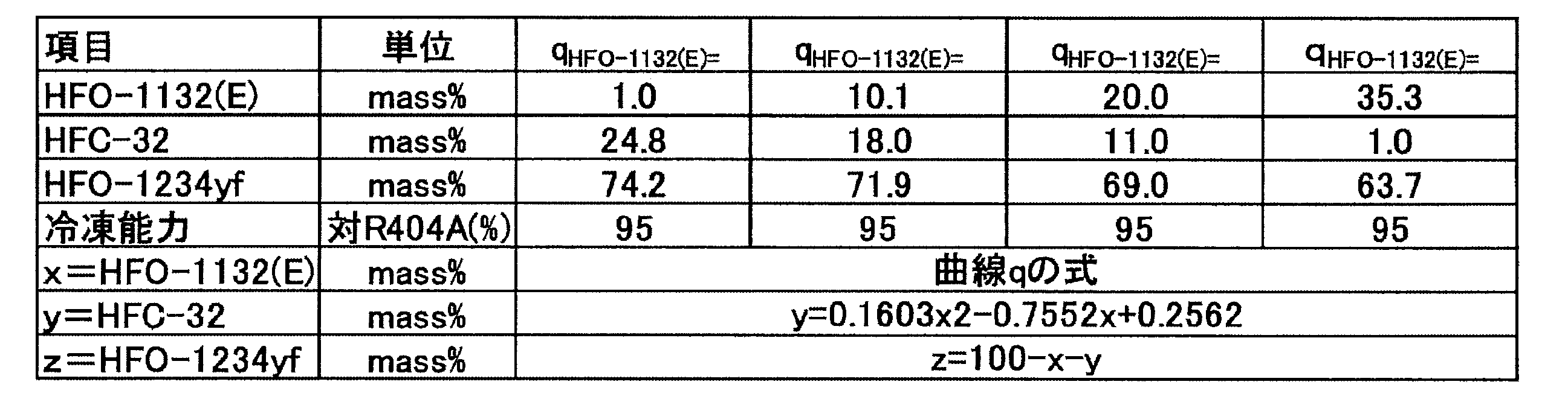
x=1.0
z=100-x-y
24.8≦y≦29.2
点R及びSは、いずれも直線s上にある。すなわち、線分RSは直線sの一部である。直線sは、GWPが200である質量比を示す直線である。直線sよりも三角組成図の頂点HFO-1132(E)側及び頂点HFO-1234yf側の領域では、三成分の混合冷媒のGWPが200未満である。
y=29.2
z=100-x-y
1.0≦x≦6.5
点P及びSは、いずれも曲線t上にある。曲線tは、40℃での圧力が1.85MPaになる質量比を示す曲線である。曲線tよりも三角組成図の頂点HFO-1234yf側の領域では、三成分の混合冷媒の40℃での圧力が1.85MPa未満である。
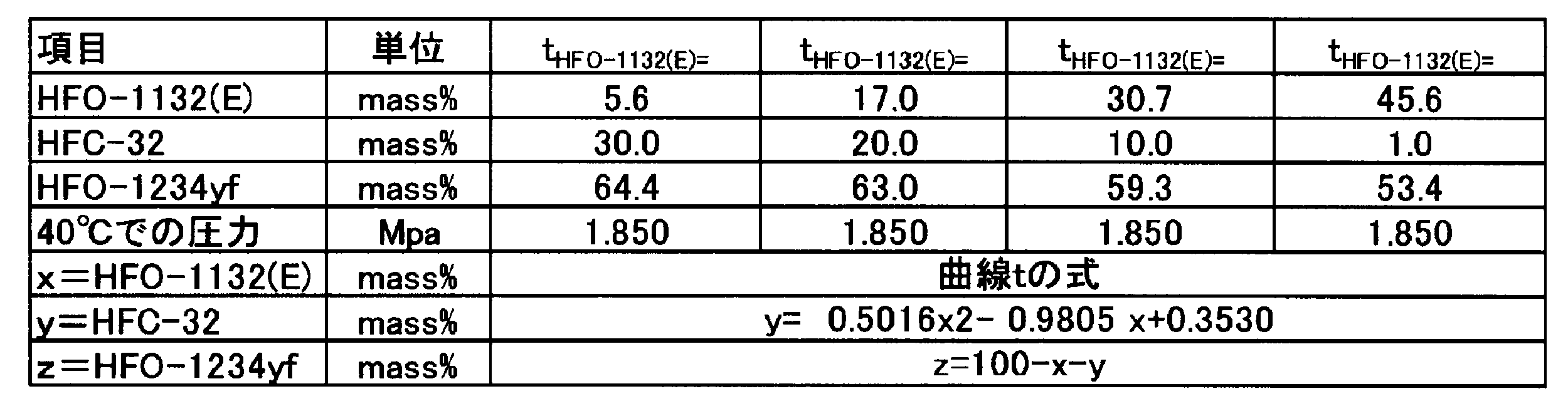
点P(HFO-1132(E)/HFC-32/HFO-1234yf=45.6/1.0/53.4質量%)、
点B(HFO-1132(E)/HFC-32/HFO-1234yf=35.3/1.0/63.7質量%)、
点Q(HFO-1132(E)/HFC-32/HFO-1234yf=1.0/24.8/74.2質量%)、
点R(HFO-1132(E)/HFC-32/HFO-1234yf=1.0/29.2/69.8質量%)及び
点S(HFO-1132(E)/HFC-32/HFO-1234yf=6.5/29.2/64.3質量%)、
の5点を通る図形で囲まれた領域の範囲内にあることが好ましい。
以下に、実施例を挙げて更に詳細に説明する。ただし、本開示は、これらの実施例に限定されるものではない。
実施例1-1~1-11、比較例1-1~1-6及び参考例1-1(R404A)に示される混合冷媒のGWPは、IPCC(Intergovernmental Panel on Climate Change)第4次報告書の値に基づいて評価した。
蒸発温度 -40℃
凝縮温度 40℃
過熱温度 20K
過冷却温度 0K
圧縮機効率 70%
COP=(冷凍能力又は暖房能力)/消費電力量
試験容器:280mmφ球形(内容積:12リットル)
試験温度:60℃±3℃
圧力:101.3kPa±0.7kPa
水分:乾燥空気1gにつき0.0088g±0.0005g(23℃における相対湿度50%の水分量)
冷媒組成物/空気混合比:1vol.%刻み±0.2vol.%
冷媒組成物混合:±0.1質量%
点火方法:交流放電、電圧15kV、電流30mA、ネオン変圧器
電極間隔:6.4mm(1/4inch)
スパーク:0.4秒±0.05秒
判定基準:
・着火点を中心に90度より大きく火炎が広がった場合=火炎伝播あり(可燃)
・着火点を中心に90度以下の火炎の広がりだった場合=火炎伝播なし(不燃)
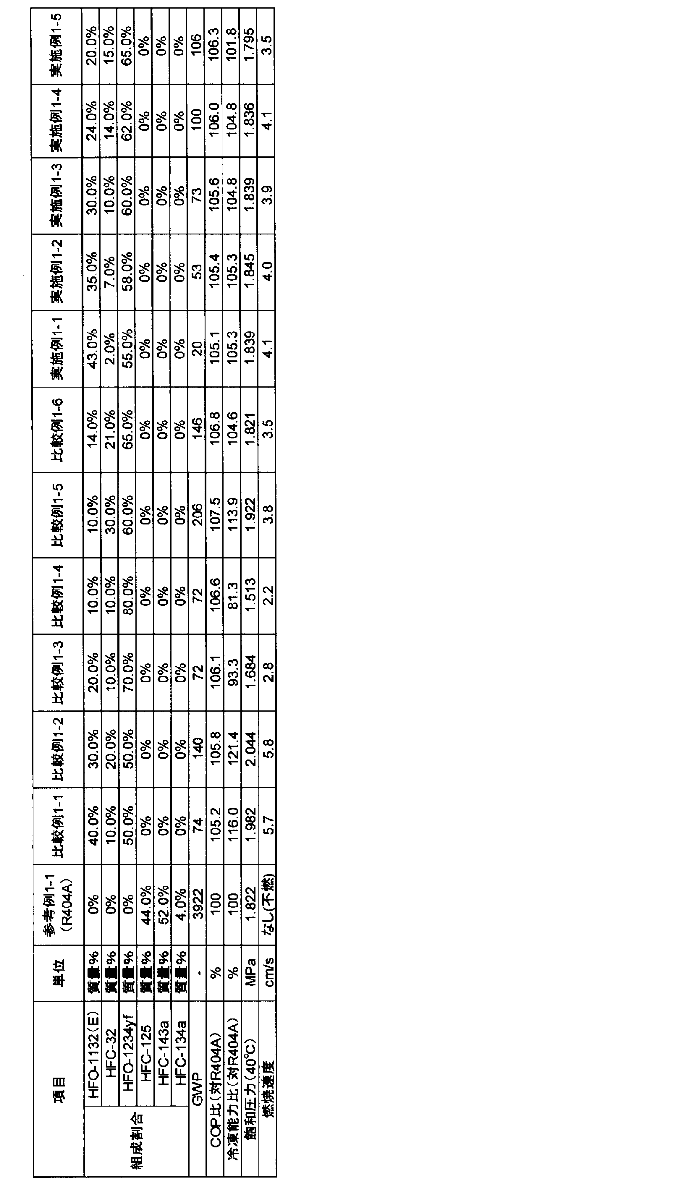

実施例2-1~2-11、比較例2-1~2-5及び参考例2-1(R404A)に示される混合冷媒のGWPは、IPCC第4次報告書の値に基づいて評価した。
蒸発温度 -40℃
凝縮温度 40℃
過熱温度 20K
過冷却温度 0K
圧縮機効率 70%
試験例2の結果を表207及び208に示す。表207及び208は、本開示の冷媒2A2の実施例及び比較例を示している。表207及び208中、各用語の意味は、試験例1と同様である。
COP=(冷凍能力又は暖房能力)/消費電力量
混合冷媒の燃焼性は、試験例1と同様にして判断した。燃焼速度試験は、試験例1と同様にして行った。
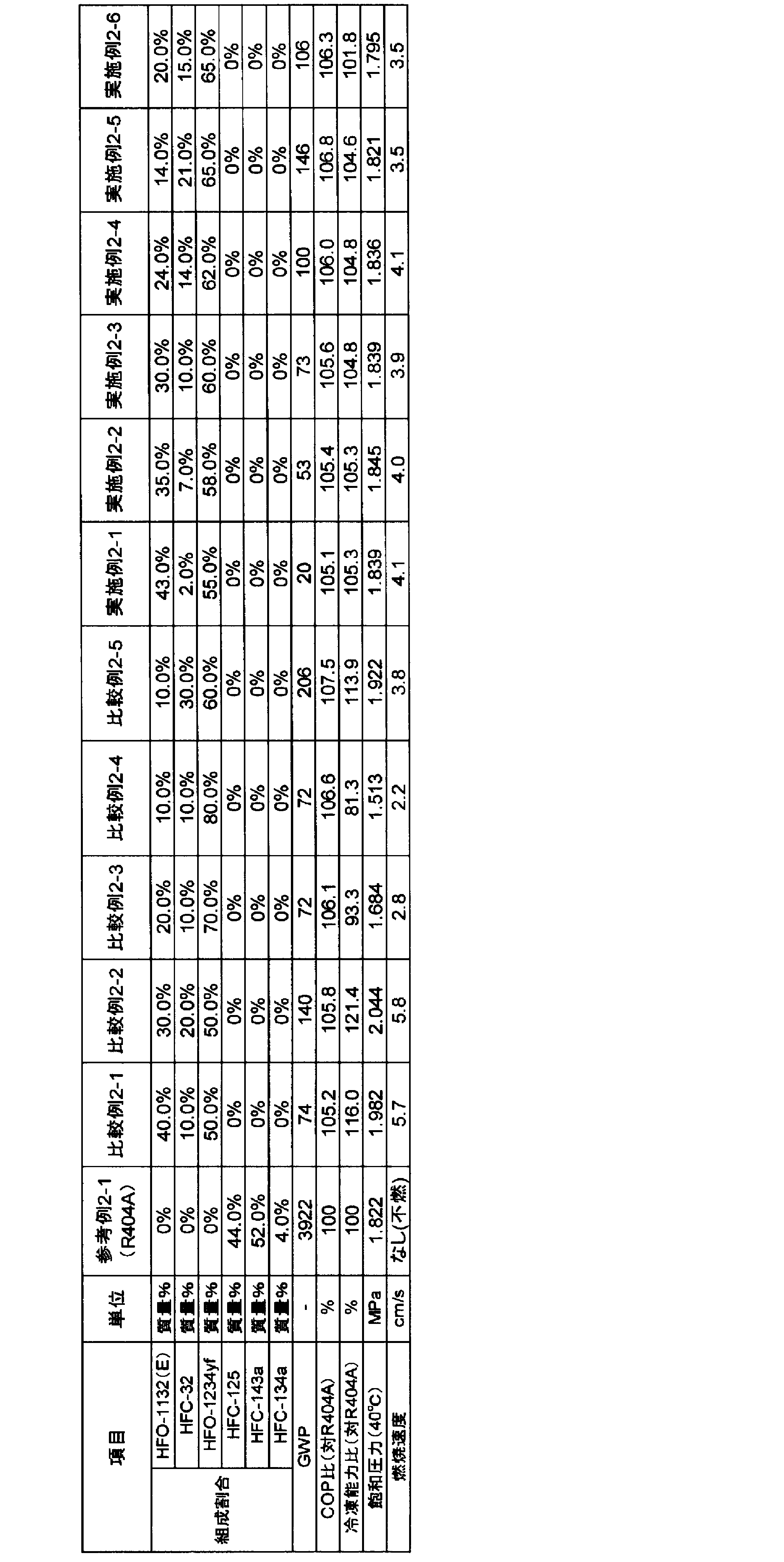

冷媒2Bは、HFO-1132(E)、HFO-1123及びHFO-1234yfを必須成分として含有する混合冷媒である。以下、本項目において、HFO-1132(E)、HFO-1123及びHFO-1234yfを「三成分」とも称する。
点A(HFO-1132(E)/HFO-1123/HFO-1234yf=42.5/1.0/56.5質量%)、
点B(HFO-1132(E)/HFO-1123/HFO-1234yf=27.1/1.0/71.9質量%)、
点C(HFO-1132(E)/HFO-1123/HFO-1234yf=1.0/30.4/68.6質量%)、
点D(HFO-1132(E)/HFO-1123/HFO-1234yf=1.0/57.0/42.0質量%)及び
点E(HFO-1132(E)/HFO-1123/HFO-1234yf=42.5/24.1/33.4質量%)
の5点を通る図形で囲まれた領域の範囲内にある。
点A(HFO-1132(E)/HFO-1123/HFO-1234yf=42.5/1.0/56.5質量%)、
点B(HFO-1132(E)/HFO-1123/HFO-1234yf=27.1/1.0/71.9質量%)、
点C(HFO-1132(E)/HFO-1123/HFO-1234yf=1.0/30.4/68.6質量%)、
点D(HFO-1132(E)/HFO-1123/HFO-1234yf=1.0/57.0/42.0質量%)及び
点E(HFO-1132(E)/HFO-1123/HFO-1234yf=42.5/24.1/33.4質量%)
の5点をそれぞれ結ぶ直線a、曲線b、直線c、曲線d及び直線eで囲まれた領域の範囲内にある。
A:ANSI/ASHRAE34-2013規格に従い測定された燃焼速度が3.0cm/sであって、HFO-1123の濃度(質量%)が1.0質量%である質量比
B:HFO-1123の濃度(質量%)が1.0質量%であって、冷凍能力がR404Aに対して85%である質量比
C:冷凍能力がR404Aに対して85%であって、HFO-1132(E)の濃度(質量%)が1.0質量%である質量比
D:HFO-1132(E)の濃度(質量%)が1.0質量%であって、40℃での飽和圧力が2.25MPaである質量比
E:40℃での飽和圧力が2.25MPaであって、ANSI/ASHRAE34-2013規格に従い測定された燃焼速度が3.0cm/sである質量比
「ANSI/ASHRAE34-2013規格に従い測定された燃焼速度が3.0cm/s」とは、ANSI/ASHRAE34-2013規格でのクラス2L(微燃)に区分するための基準である燃焼速度(10cm/s)の半分未満の数値であり、クラス2Lに規定される冷媒の中でも比較的安全であることを意味する。
具体的には、「燃焼速度(10cm/s)の半分未満の数値」であると、万が一着火した場合にも火炎が伝播しにくいという点で比較的安全である。なお、以下ANSI/ASHRAE34-2013規格に従い測定された燃焼速度を、単に「燃焼速度」とも称する。
y=1.0
z=100-x-y
27.1≦x≦42.5
点B及びCは、いずれも曲線b上にある。曲線bは、冷凍能力がR404Aに対して85%である質量比を示す曲線である。曲線bよりも三角組成図の頂点HFO-1132(E)側及び頂点HFO-1123側の領域では、三成分の混合冷媒の冷凍能力がR404Aに対して85%を超える。

x=1.0
z=100-x-y
30.4≦y≦57.0
点D及びEは、いずれも曲線d上にある。曲線dは、40℃での飽和圧力が2.25MPaである質量比を示す曲線である。曲線dよりも三角組成図の頂点HFO-1234yf側の領域では、三成分の混合冷媒は、40℃での飽和圧力が2.25MPa未満である。

x=42.5
z=100-x-y
1.0≦y≦24.1
HFO-1132(E)、HFO-1123及びHFO-1234yfの三元混合冷媒は、点A、B、C、D及びEの5点をそれぞれ結ぶ線で囲まれた領域(ABCDE領域)の範囲内の質量比において、(1)GWPが125以下であること、(2)冷凍能力が対R404A比で85%以上であること、(3)40℃での飽和圧力が2.25MPa以下であること、及び(4)燃焼速度が3.0cm/s以下であること、という諸特性を有する。
点A(HFO-1132(E)/HFO-1123/HFO-1234yf=42.5/1.0/56.5質量%)、
点B(HFO-1132(E)/HFO-1123/HFO-1234yf=27.1/1.0/71.9質量%)、
点C(HFO-1132(E)/HFO-1123/HFO-1234yf=1.0/30.4/68.6質量%)、
点F(HFO-1132(E)/HFO-1123/HFO-1234yf=1.0/52.2/46.8質量%)及び
点G(HFO-1132(E)/HFO-1123/HFO-1234yf=42.5/18.9/38.6質量%)
の5点を通る図形で囲まれた領域の範囲内にあることが好ましい。
点A(HFO-1132(E)/HFO-1123/HFO-1234yf=42.5/1.0/56.5質量%)、
点B(HFO-1132(E)/HFO-1123/HFO-1234yf=27.1/1.0/71.9質量%)、
点C(HFO-1132(E)/HFO-1123/HFO-1234yf=1.0/30.4/68.6質量%)、
点F(HFO-1132(E)/HFO-1123/HFO-1234yf=1.0/52.2/46.8質量%)及び
点G(HFO-1132(E)/HFO-1123/HFO-1234yf=42.5/18.9/38.6質量%)
の5点をそれぞれ結ぶ直線a、曲線b、直線c、曲線f及び直線eで囲まれた領域の範囲内にあることが好ましい。
F:HFO-1132(E)の濃度(質量%)が1.0質量%であって、40℃での飽和圧力が2.15MPaである質量比
G:40℃での飽和圧力が2.15MPaであって、ANSI/ASHRAE34-2013規格に従い測定された燃焼速度が3.0cm/sである質量比
直線a、曲線b、直線c及び直線eについては、上記の通りである。点Fは直線c上にあり、点Gは直線e上にある。
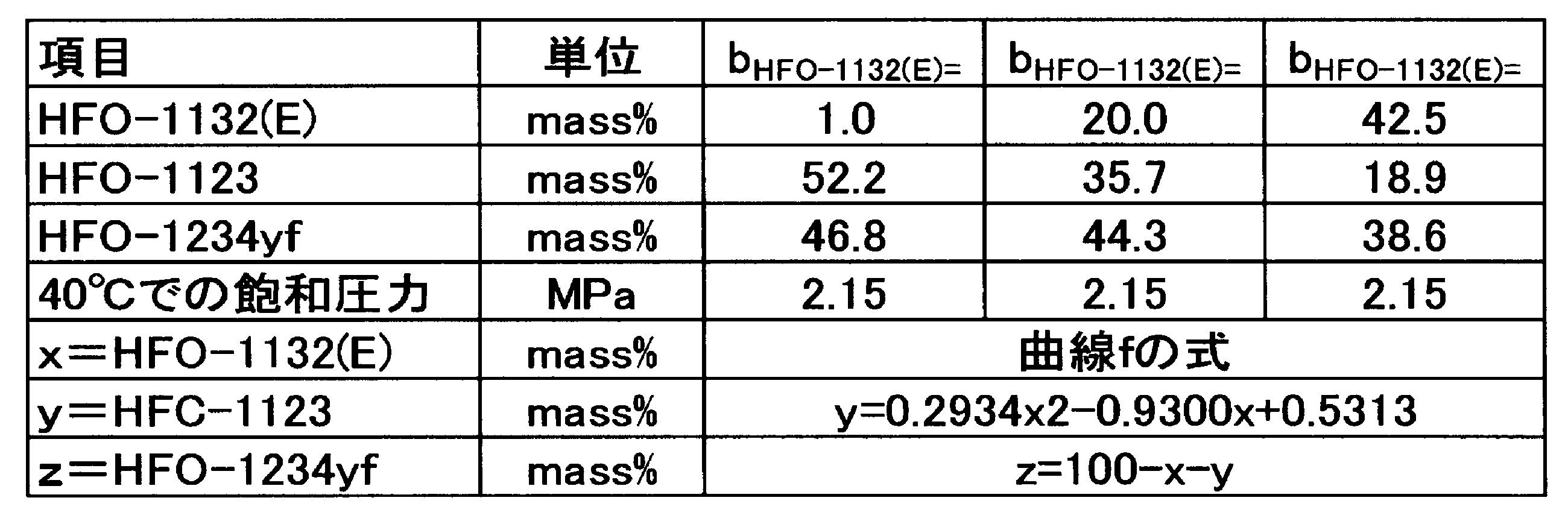
点A(HFO-1132(E)/HFO-1123/HFO-1234yf=42.5/1.0/56.5質量%)、
点B(HFO-1132(E)/HFO-1123/HFO-1234yf=27.1/1.0/71.9質量%)、
点C(HFO-1132(E)/HFO-1123/HFO-1234yf=1.0/30.4/68.6質量%)、
点H(HFO-1132(E)/HFO-1123/HFO-1234yf=1.0/35.2/63.8質量%)、
点I(HFO-1132(E)/HFO-1123/HFO-1234yf=27.4/29.8/42.8質量%)及び
点G(HFO-1132(E)/HFO-1123/HFO-1234yf=42.5/18.9/38.6質量%)
の6点を通る図形で囲まれた領域の範囲内にあることが好ましい。
点A(HFO-1132(E)/HFO-1123/HFO-1234yf=42.5/1.0/56.5質量%)、
点B(HFO-1132(E)/HFO-1123/HFO-1234yf=27.1/1.0/71.9質量%)、
点C(HFO-1132(E)/HFO-1123/HFO-1234yf=1.0/30.4/68.6質量%)、
点H(HFO-1132(E)/HFO-1123/HFO-1234yf=1.0/35.2/63.8質量%)、
点I(HFO-1132(E)/HFO-1123/HFO-1234yf=27.4/29.8/42.8質量%)及び
点G(HFO-1132(E)/HFO-1123/HFO-1234yf=42.5/18.9/38.6質量%)
の6点をそれぞれ結ぶ直線a、曲線b、直線c、曲線g、曲線f及び直線eで囲まれた領域の範囲内にあることが好ましい。
H:HFO-1132(E)の濃度(質量%)が1.0質量%であって、COPがR404Aに対して100%である質量比
I:COPがR404Aに対して100%であって、40℃での飽和圧力が2.15MPaである質量比
直線a、曲線b、直線c、直線e及び曲線fについては、上記の通りである。点Hは直線c上にあり、点Iは曲線f上にある。
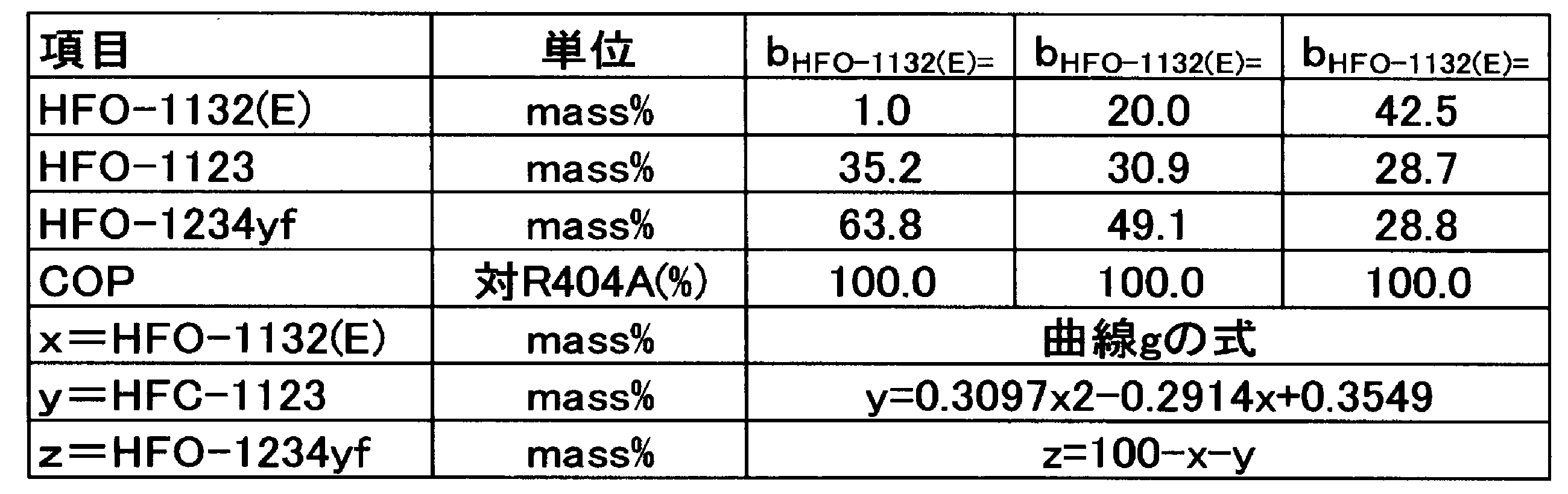
点A(HFO-1132(E)/HFO-1123/HFO-1234yf=42.5/1.0/56.5質量%)、
点B(HFO-1132(E)/HFO-1123/HFO-1234yf=27.1/1.0/71.9質量%)、
点C(HFO-1132(E)/HFO-1123/HFO-1234yf=1.0/30.4/68.6質量%)、
点D(HFO-1132(E)/HFO-1123/HFO-1234yf=1.0/57.0/42.0質量%)及び
点E(HFO-1132(E)/HFO-1123/HFO-1234yf=42.5/24.1/33.4質量%)
の5点を通る図形で囲まれた領域の範囲内にあることが好ましい。
点A(HFO-1132(E)/HFO-1123/HFO-1234yf=42.5/1.0/56.5質量%)、
点B(HFO-1132(E)/HFO-1123/HFO-1234yf=27.1/1.0/71.9質量%)、
点C(HFO-1132(E)/HFO-1123/HFO-1234yf=1.0/30.4/68.6質量%)、
点F(HFO-1132(E)/HFO-1123/HFO-1234yf=1.0/52.2/46.8質量%)及び
点G(HFO-1132(E)/HFO-1123/HFO-1234yf=42.5/18.9/38.6質量%)
の5点を通る図形で囲まれた領域の範囲内にあることがより好ましい。
点A(HFO-1132(E)/HFO-1123/HFO-1234yf=42.5/1.0/56.5質量%)、
点B(HFO-1132(E)/HFO-1123/HFO-1234yf=27.1/1.0/71.9質量%)、
点C(HFO-1132(E)/HFO-1123/HFO-1234yf=1.0/30.4/68.6質量%)、
点H(HFO-1132(E)/HFO-1123/HFO-1234yf=1.0/35.2/63.8質量%)、
点I(HFO-1132(E)/HFO-1123/HFO-1234yf=27.4/29.8/42.8質量%)及び
点G(HFO-1132(E)/HFO-1123/HFO-1234yf=42.5/18.9/38.6質量%)
の6点を通る図形で囲まれた領域の範囲内にあることが更に好ましい。
以下に、実施例を挙げて更に詳細に説明する。ただし、本開示は、これらの実施例に限定されるものではない。
実施例1~38、比較例1~9及び参考例1(R404A)に示される混合冷媒のGWPは、IPCC(Intergovernmental Panel on Climate Change)第4次報告書の値に基づいて評価した。
蒸発温度 -40℃
凝縮温度 40℃
過熱温度 20K
過冷却温度 0K
圧縮機効率 70%
COP=(冷凍能力又は暖房能力)/消費電力量
試験容器:280mmφ球形(内容積:12リットル)
試験温度:60℃±3℃
圧力:101.3kPa±0.7kPa
水分:乾燥空気1gにつき0.0088g±0.0005g(23℃における相対湿度50%の水分量)
冷媒組成物/空気混合比:1vol.%刻み±0.2vol.%
冷媒組成物混合:±0.1質量%
点火方法:交流放電、電圧15kV、電流30mA、ネオン変圧器
電極間隔:6.4mm(1/4inch)
スパーク:0.4秒±0.05秒
判定基準:
・着火点を中心に90度より大きく火炎が広がった場合=火炎伝播あり(可燃)
・着火点を中心に90度以下の火炎の広がりだった場合=火炎伝播なし(不燃)

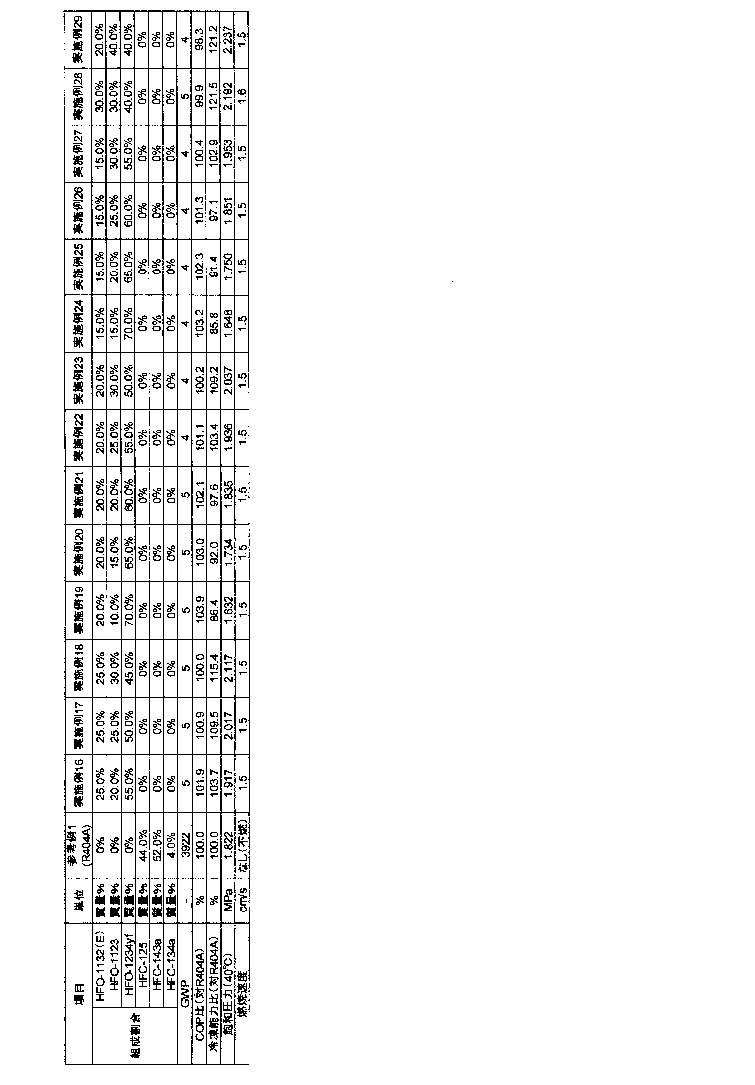

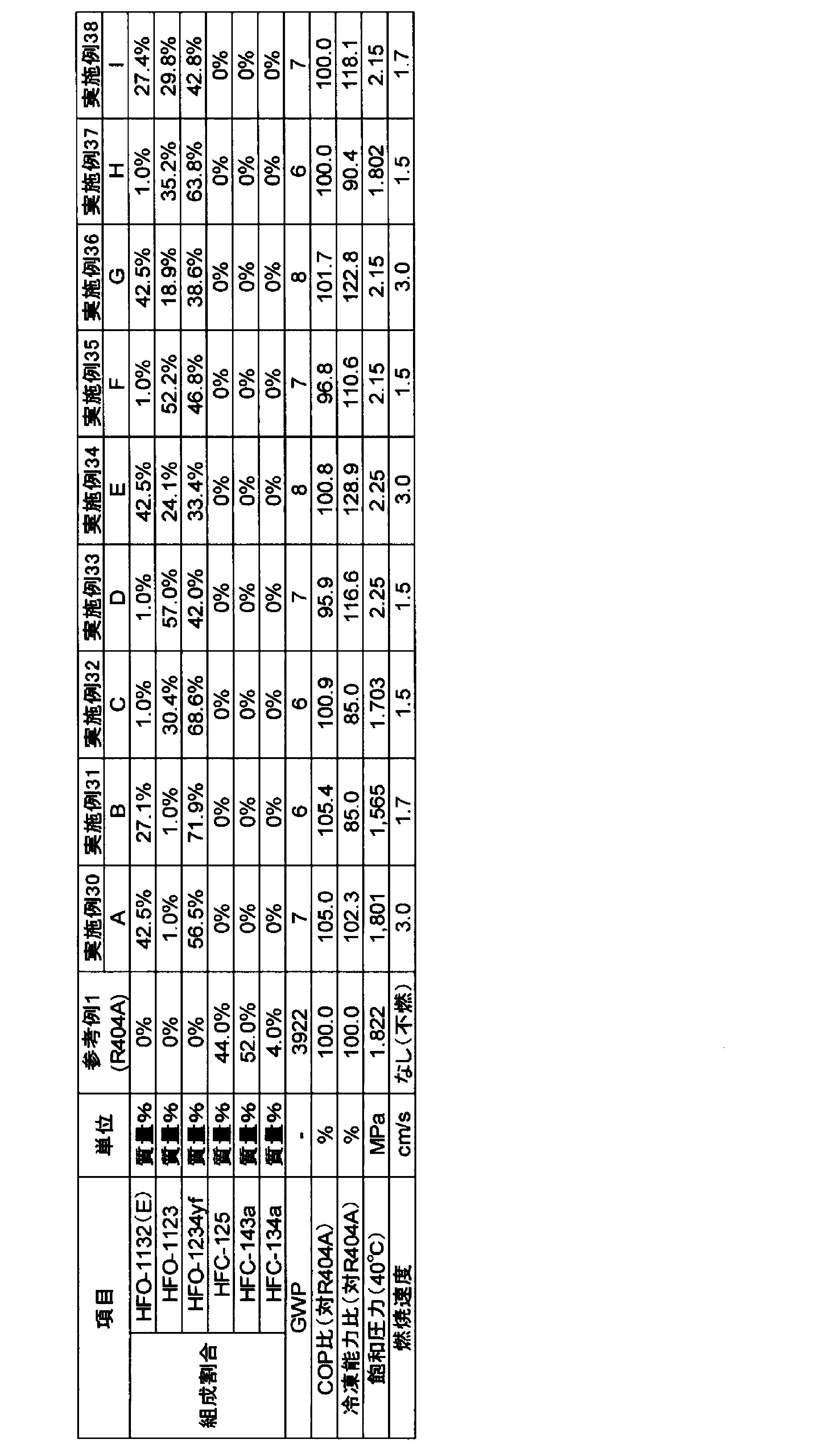
冷媒2Cは、一つの態様において、HFO-1132(E)及びHFO-1234yfを含有し、HFO-1132(E)及びHFO-1234yfの全質量に対して、HFO-1132(E)の含有割合は35.0~65.0質量%であり、HFO-1234yfの含有割合は65.0~35.0質量%である。この冷媒を「冷媒2C1」ということがある。
冷媒2C1は、上述の構成を有することによって、(1)GWPが十分小さいこと(100以下)、(2)R404Aと同等又はそれ以上のCOPを有すること、及び(3)R404Aと同等又はそれ以上の冷凍能力を有すること、という諸特性を有する。
また、冷媒2C1において、HFO-1132(E)及びHFO-1234yfの全質量に対する、HFO-1132(E)の含有割合が65.0質量%以下であることにより、冷媒2C1の冷凍サイクルにおける飽和温度40℃の飽和圧力を好適な範囲(特に2.10Mpa以下)に維持することができる。
圧縮比=凝縮圧力(Mpa)/蒸発圧力(Mpa)
更にこの場合、冷媒2C1は、飽和温度40℃における飽和圧力が、1.75MPa以上2.00MPa以下となるため、市販のR404A用冷凍装置に対して大きな設計変更なく適用することができる。
本開示の組成物に含まれる冷媒は、一つの態様において、HFO-1132(E)及びHFO-1234yfを含有し、HFO-1132(E)及びHFO-1234yfの全質量に対して、HFO-1132(E)の含有割合が40.5~49.2質量%であり、HFO-1234yfの含有割合が59.5~50.8質量%である。この冷媒を「冷媒2C2」ということがある。
また、冷媒2C2において、HFO-1132(E)及びHFO-1234yfの全質量に対する、HFO-1132(E)の含有割合が49.2質量%以下であることにより、冷媒2C2の冷凍サイクルにおける飽和温度40℃の飽和圧力を好適な範囲(特に2.10Mpa以下)に維持することができる。
更にこの場合、冷媒2C2は、飽和温度40℃の飽和圧力が、1.76MPa以上1.88MPa以下となり、市販のR404A用冷凍装置に対して大きな設計変更なく適用することができる。
本開示の組成物に含まれる冷媒は、一つの態様において、HFO-1132(E)及びHFO-1234yfを含有し、HFO-1132(E)及びHFO-1234yfの全質量に対して、HFO-1132(E)の含有割合が31.1~39.8質量%であり、HFO-1234yfの含有割合が68.9~60.2質量%である。この冷媒を「冷媒2C3」ということがある。
また、冷媒2C3において、HFO-1132(E)及びHFO-1234yfの全質量に対する、HFO-1132(E)の含有割合が39.8質量%以下であることにより、冷媒2C3の冷凍サイクルにおける吐出温度を90℃以下に維持し、R134a用冷凍装置の部材の寿命を長く確保することができる。
冷媒2C3は、このような構成を有することによって、(1)GWPが十分小さいこと(100以下)、(2)R134aと同等程度のCOPを有すること、(3)R134aと比べて150%以上の冷凍能力を有すること、及び(4)吐出温度が90.0℃以下であることという、諸特性を有する。
本開示の組成物に含まれる冷媒は、一つの態様において、HFO-1132(E)及びHFO-1234yfを含有し、HFO-1132(E)及びHFO-1234yfの全質量に対して、HFO-1132(E)の含有割合が21.0~28.4質量%であり、HFO-1234yfの含有割合が79.0~71.6質量%である。この冷媒を「冷媒2C4」ということがある。
本開示の組成物に含まれる冷媒は、一つの態様において、HFO-1132(E)及びHFO-1234yfを含有し、HFO-1132(E)及びHFO-1234yfの全質量に対して、HFO-1132(E)の含有割合は12.1~72.0質量%であり、HFO-1234yfの含有割合は87.9~28.0質量%である。この冷媒を「冷媒2C5」ということがある。
以下に、実施例を挙げて更に詳細に説明する。ただし、本開示は、これらの実施例に限定されるものではない。
実施例1-1~1-13、比較例1-1~1-2及び参考例1-1(R404A)に示される混合冷媒のGWPは、IPCC第4次報告書の値に基づいて評価した。
蒸発温度 -50℃
凝縮温度 40℃
過熱温度 20K
過冷却温度 0K
圧縮機効率 70%
表217中、「飽和圧力(40℃)」とは、飽和温度40℃における飽和圧力を示す。表217中、「吐出温度(℃)」とは、上記混合冷媒の冷凍サイクル理論計算において、冷凍サイクル中で最も温度が高くなる温度を示す。
COP=(冷凍能力又は暖房能力)/消費電力量
圧縮比=凝縮圧力(Mpa)/蒸発圧力(Mpa)
試験容器:280mmφ球形(内容積:12リットル)
試験温度:60℃±3℃
圧力:101.3kPa±0.7kPa
水分:乾燥空気1gにつき0.0088g±0.0005g(23℃における相対湿度50%の水分量)冷媒組成物/空気混合比:1vol.%刻み±0.2vol.%
冷媒組成物混合:±0.1質量%
点火方法:交流放電、電圧15kV、電流30mA、ネオン変圧器
電極間隔:6.4mm(1/4inch)
スパーク:0.4秒±0.05秒
判定基準:
・着火点を中心に90度より大きく火炎が広がった場合=火炎伝播あり(可燃)
・着火点を中心に90度以下の火炎の広がりだった場合=火炎伝播なし(不燃)
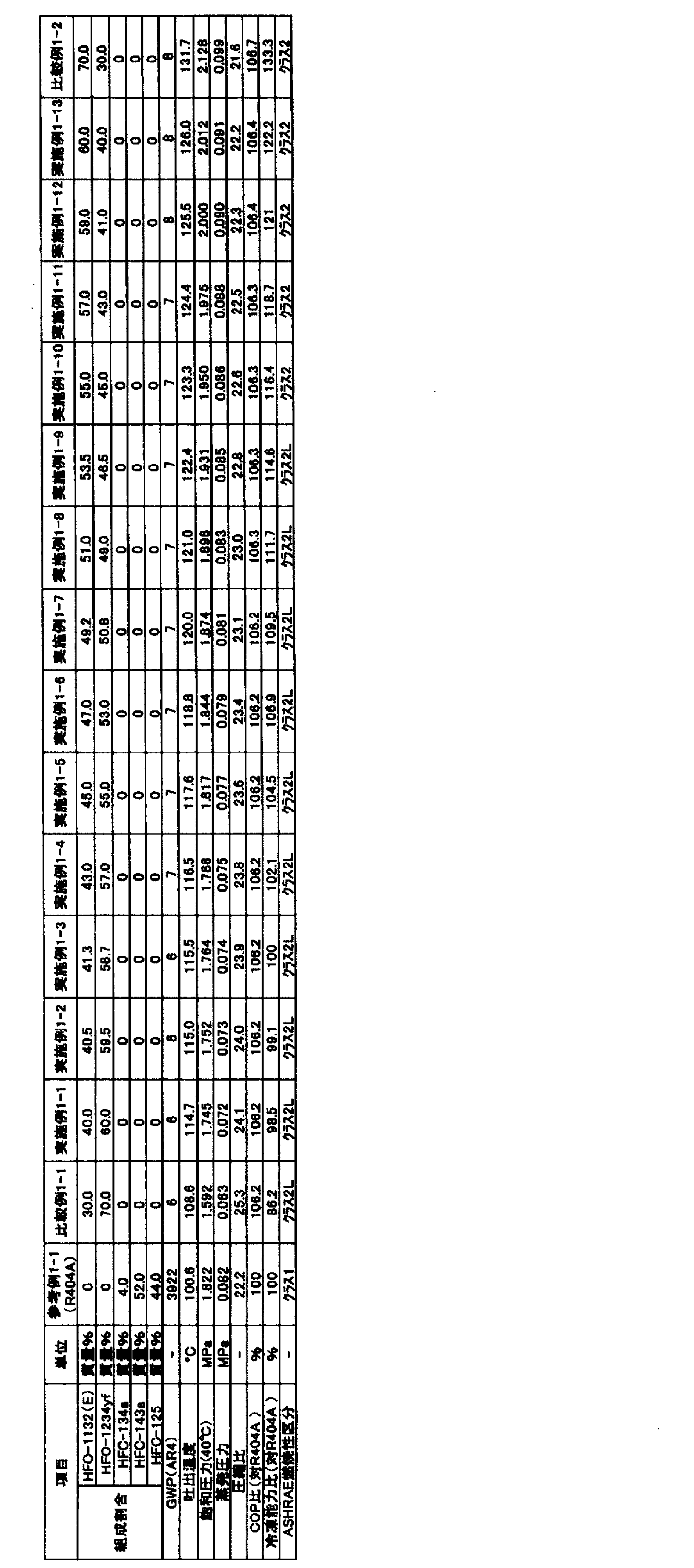
実施例1-14~1-26、比較例1-3~1-4及び参考例1-2(R404A)に示される混合冷媒のGWPは、IPCC第4次報告書の値に基づいて評価した。
蒸発温度 -35℃
凝縮温度 40℃
過熱温度 20K
過冷却温度 0K
圧縮機効率 70%
上記用語の意味は、試験例1-1と同様である。
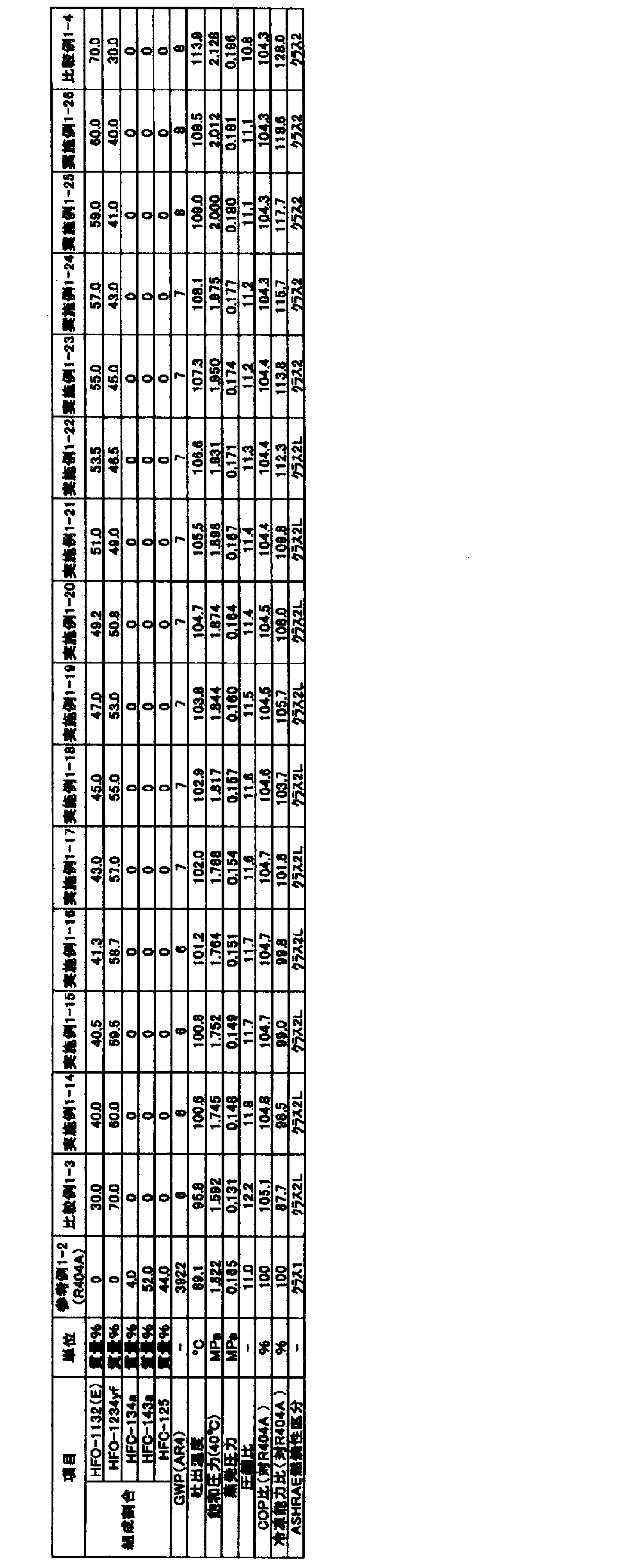
実施例1-27~1-39、比較例1-5~1-6及び参考例1-3(R404A)に示される混合冷媒のGWPは、IPCC第4次報告書の値に基づいて評価した。
蒸発温度 -10℃
凝縮温度 40℃
過熱温度 20K
過冷却温度 0K
圧縮機効率 70%
上記用語の意味は、試験例1-1と同様である。
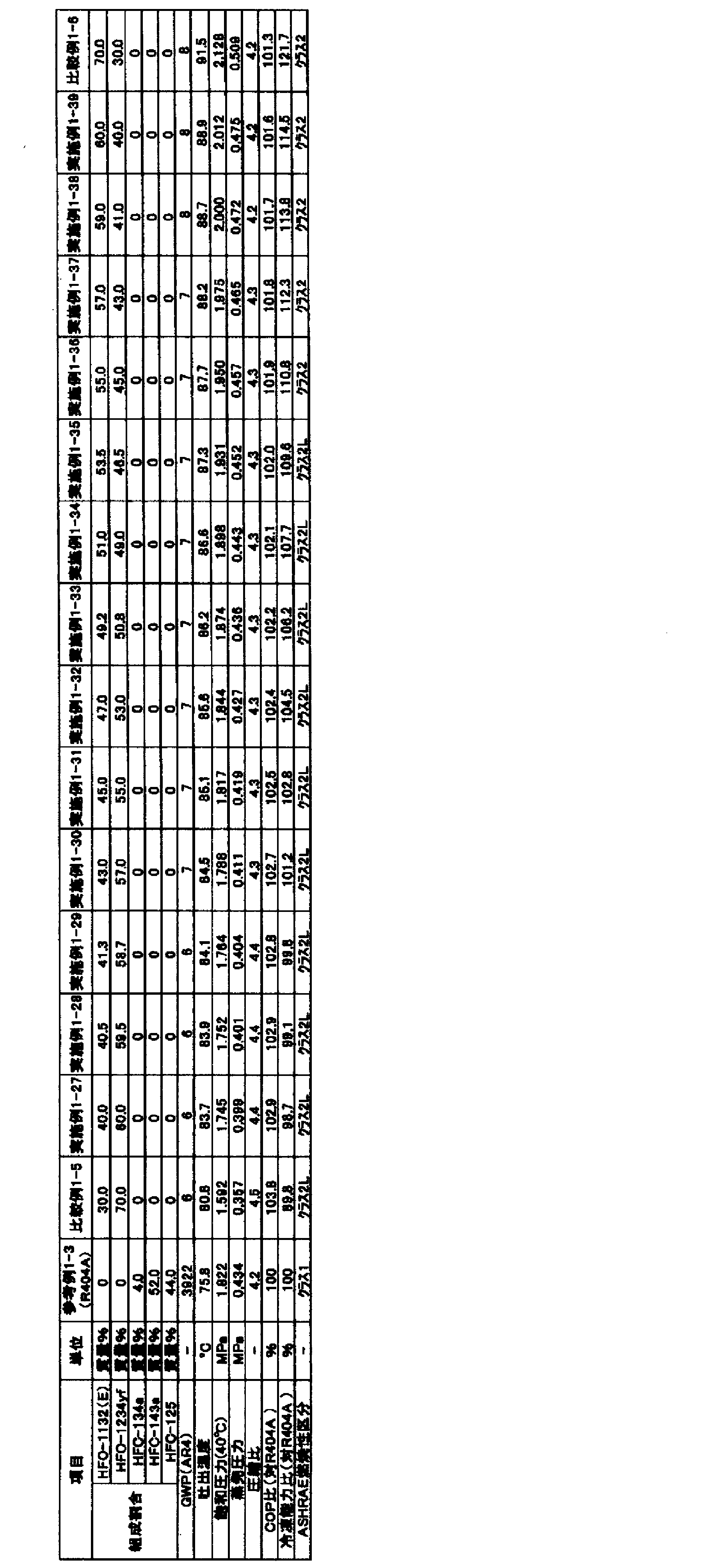
比較例1-7~1-21及び参考例1-4(R404A)に示される混合冷媒のGWPは、IPCC第4次報告書の値に基づいて評価した。
蒸発温度 -80℃
凝縮温度 40℃
過熱温度 20K
過冷却温度 0K
圧縮機効率 70%

比較例1-22~1-36及び参考例1-5(R404A)に示される混合冷媒のGWPは、IPCC第4次報告書の値に基づいて評価した。
蒸発温度 10℃
凝縮温度 40℃
過熱温度 20K
過冷却温度 0K
圧縮機効率 70%
上記用語の意味は、試験例1-1と同様である。

実施例2-1~2-6、比較例2-1~2-9及び参考例2-1(R404A)に示される混合冷媒のGWPは、IPCC第4次報告書の値に基づいて評価した。
蒸発温度 -50℃
凝縮温度 40℃
過熱温度 20K
過冷却温度 0K
圧縮機効率 70%
表222中、「飽和圧力(40℃)」とは、飽和温度40℃における飽和圧力を示す。表222中、「吐出温度(℃)」とは、上記混合冷媒の冷凍サイクル理論計算において、冷凍サイクル中で最も温度が高くなる温度を示す。
COP=(冷凍能力又は暖房能力)/消費電力量
圧縮比=凝縮圧力(Mpa)/蒸発圧力(Mpa)
試験容器:280mmφ球形(内容積:12リットル)
試験温度:60℃±3℃
圧力:101.3kPa±0.7kPa
水分:乾燥空気1gにつき0.0088g±0.0005g(23℃における相対湿度50%の水分量)冷媒組成物/空気混合比:1vol.%刻み±0.2vol.%
冷媒組成物混合:±0.1質量%
点火方法:交流放電、電圧15kV、電流30mA、ネオン変圧器
電極間隔:6.4mm(1/4inch)
スパーク:0.4秒±0.05秒
判定基準:
・着火点を中心に90度より大きく火炎が広がった場合=火炎伝播あり(可燃)
・着火点を中心に90度以下の火炎の広がりだった場合=火炎伝播なし(不燃)

実施例2-7~2-12、比較例2-10~2-18及び参考例2-2(R404A)に示される混合冷媒のGWPは、IPCC第4次報告書の値に基づいて評価した。
蒸発温度 -35℃
凝縮温度 40℃
過熱温度 20K
過冷却温度 0K
圧縮機効率 70%
上記用語の意味は、試験例2-1と同様である。

実施例2-13~2-18、比較例2-19~2-27及び参考例2-3(R404A)に示される混合冷媒のGWPは、IPCC第4次報告書の値に基づいて評価した。
蒸発温度 -10℃
凝縮温度 40℃
過熱温度 20K
過冷却温度 0K
圧縮機効率 70%
上記用語の意味は、試験例2-1と同様である。
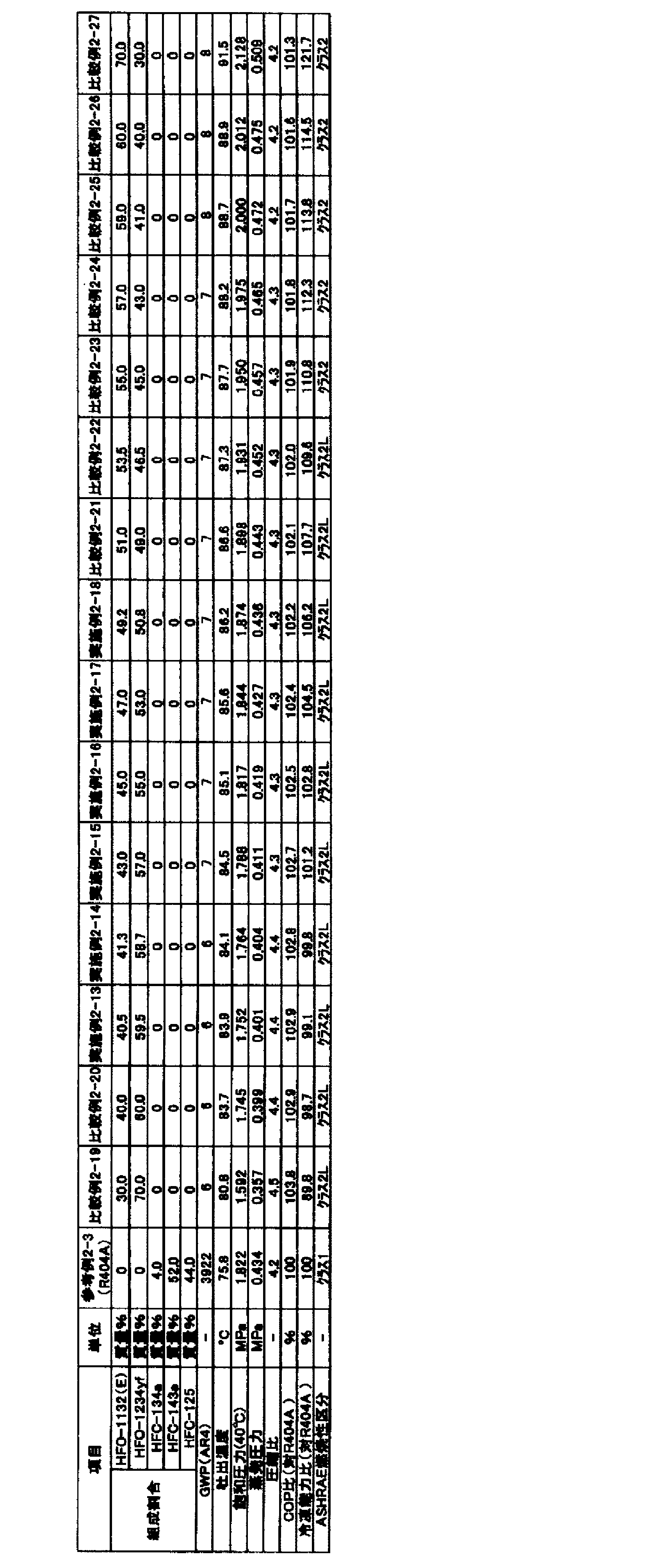
実施例2-19~2-24、比較例2-28~2-36及び参考例2-4(R404A)に示される混合冷媒のGWPは、IPCC第4次報告書の値に基づいて評価した。
蒸発温度 -80℃
凝縮温度 40℃
過熱温度 20K
過冷却温度 0K
圧縮機効率 70%

実施例2-25~2-30、比較例2-37~2-45及び参考例2-5(R404A)に示される混合冷媒のGWPは、IPCC第4次報告書の値に基づいて評価した。
蒸発温度 10℃
凝縮温度 40℃
過熱温度 20K
過冷却温度 0K
圧縮機効率 70%
上記用語の意味は、試験例2-1と同様である。
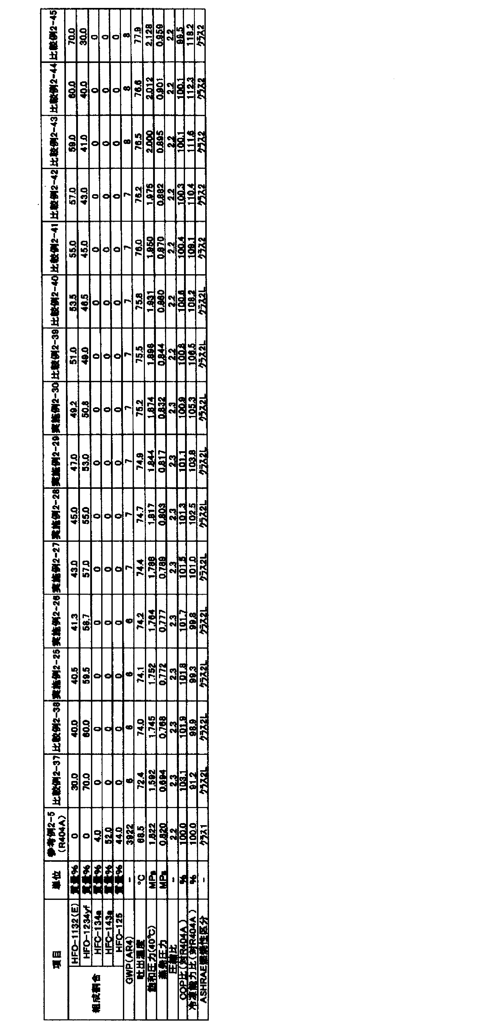
実施例3-1~3-5、比較例3-1~3-5、参考例3-1(R134a)及び参考例3-2(R404A)に示される混合冷媒のGWPは、IPCC第4次報告書の値に基づいて評価した。
蒸発温度 -10℃
凝縮温度 45℃
過熱温度 20K
過冷却温度 0K
圧縮機効率 70%
「蒸発温度-10℃」とは、冷凍装置が備える蒸発器における混合冷媒の蒸発温度が-10℃であることを意味する。また、「凝縮温度45℃」とは、冷凍装置が備える凝縮器における混合冷媒の凝縮温度が45℃であることを意味する。
COP=(冷凍能力又は暖房能力)/消費電力量
臨界温度は、National Institute of Science and Technology(NIST)及びReference Fluid Thermodynamic and Transport Properties Database(Refprop 9.0)を使用し、計算を実施することにより求めた。
試験容器:280mmφ球形(内容積:12リットル)
試験温度:60℃±3℃
圧力:101.3kPa±0.7kPa
水分:乾燥空気1gにつき0.0088g±0.0005g(23℃における相対湿度50%の水分量)冷媒組成物/空気混合比:1vol.%刻み±0.2vol.%
冷媒組成物混合:±0.1質量%
点火方法:交流放電、電圧15kV、電流30mA、ネオン変圧器
電極間隔:6.4mm(1/4inch)
スパーク:0.4秒±0.05秒
判定基準:
・着火点を中心に90度より大きく火炎が広がった場合=火炎伝播あり(可燃)
・着火点を中心に90度以下の火炎の広がりだった場合=火炎伝播なし(不燃)

実施例4-1~4-7及び比較例4-1~4-5に示される混合冷媒のGWPは、IPCC第4次報告書の値に基づいて評価した。
蒸発温度 5℃
凝縮温度 45℃
過熱温度 5K
過冷却温度 5K
圧縮機効率 70%
「蒸発温度 5℃」とは、冷凍装置が備える蒸発器における混合冷媒の蒸発温度が5℃であることを意味する。また、「凝縮温度 45℃」とは、冷凍装置が備える凝縮器における混合冷媒の凝縮温度が45℃であることを意味する。
COP=(冷凍能力又は暖房能力)/消費電力量
臨界温度は、National Institute of Science and Technology(NIST)及びReference Fluid Thermodynamic and Transport Properties Database(Refprop 9.0)を使用し、計算を実施することにより求めた。
試験容器:280mmφ球形(内容積:12リットル)
試験温度:60℃±3℃
圧力:101.3kPa±0.7kPa
水分:乾燥空気1gにつき0.0088g±0.0005g(23℃における相対湿度50%の水分量)
冷媒組成物/空気混合比:1vol.%刻み±0.2vol.%
冷媒組成物混合:±0.1質量%
点火方法:交流放電、電圧15kV、電流30mA、ネオン変圧器
電極間隔:6.4mm(1/4inch)
スパーク:0.4秒±0.05秒
判定基準:
・着火点を中心に90度より大きく火炎が広がった場合=火炎伝播あり(可燃)
・着火点を中心に90度以下の火炎の広がりだった場合=火炎伝播なし(不燃)
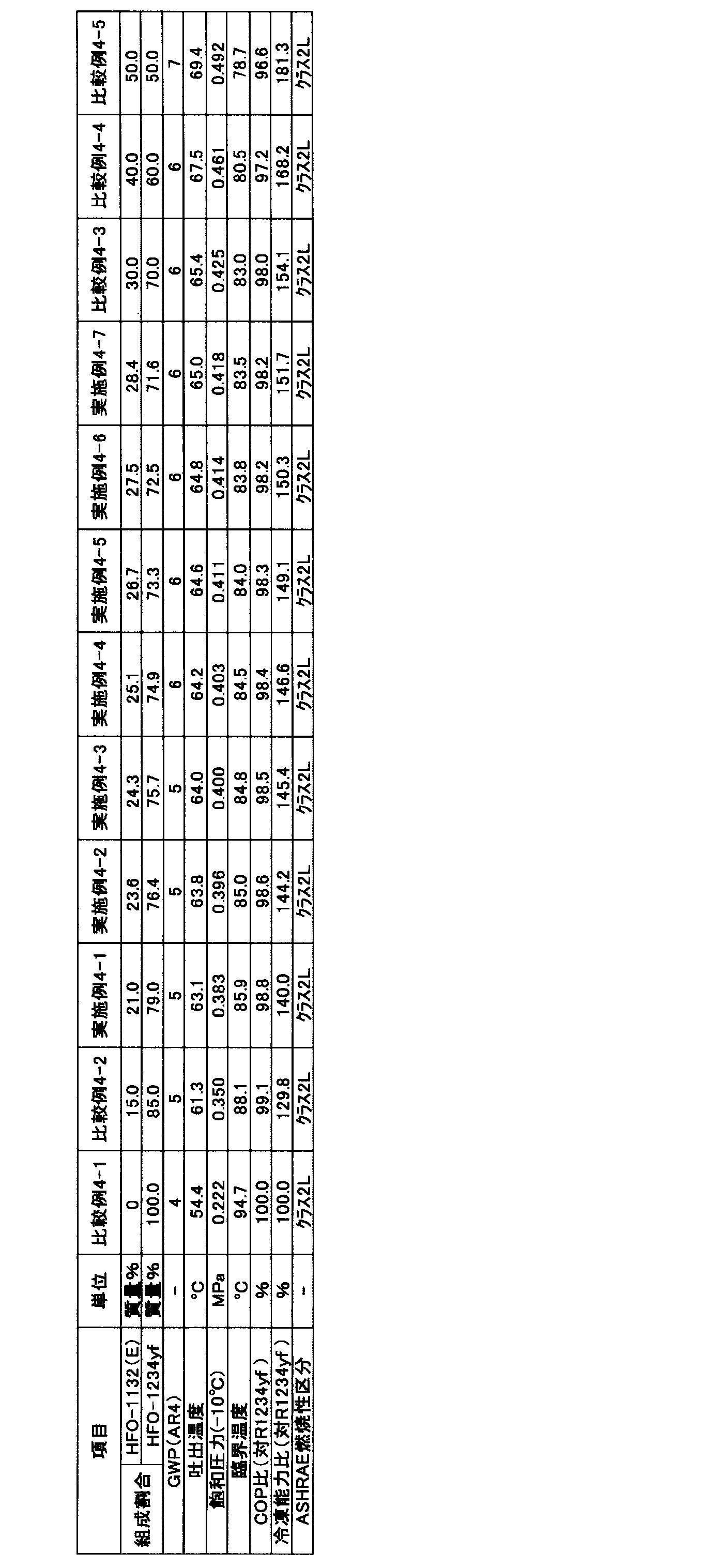
実施例5-1~5-13、比較例5-1~5-3及び参考例5-1(R134a)に示される混合冷媒のGWPは、IPCC第4次報告書の値に基づいて評価した。
蒸発温度 -30℃
凝縮温度 30℃
過熱温度 5K
過冷却温度 5K
圧縮機効率 70%
「蒸発温度 -30℃」とは、冷凍装置が備える蒸発器における混合冷媒の蒸発温度が-30℃であることを意味する。また、「凝縮温度 30℃」とは、冷凍装置が備える凝縮器における混合冷媒の凝縮温度が30℃であることを意味する。
COP=(冷凍能力又は暖房能力)/消費電力量
混合冷媒の燃焼性は、混合冷媒の混合組成をWCF濃度とし、ANSI/ASHRAE34-2013規格に従い燃焼速度を測定することにより判断した。燃焼速度の測定は以下の通り行った。まず、使用した混合冷媒は99.5%又はそれ以上の純度とし、真空ゲージ上に空気の痕跡が見られなくなるまで凍結、ポンピング及び解凍のサイクルを繰り返すことにより脱気した。閉鎖法により燃焼速度を測定した。初期温度は周囲温度とした。点火は、試料セルの中心で電極間に電気的スパークを生じさせることにより行った。放電の持続時間は1.0~9.9msとし、点火エネルギーは典型的には約0.1~1.0Jであった。シュリーレン写真を使って炎の広がりを視覚化した。光を通す2つのアクリル窓を備えた円筒形容器(内径:155mm、長さ:198mm)を試料セルとして用い、光源としてはキセノンランプを用いた。炎のシュリーレン画像を高速デジタルビデオカメラで600fpsのフレーミング速度で記録し、PCに保存した。
暖房使用時の消費電力量=暖房能力/暖房COP
なお、暖房COPとは「暖房効率」を意味する。
蒸発温度 -30℃
凝縮温度 30℃
過熱温度 5K
過冷却温度 5K
圧縮機効率 70%
走行可能距離=(電池容量)/(動力の消費電力量+暖房での消費電力量)
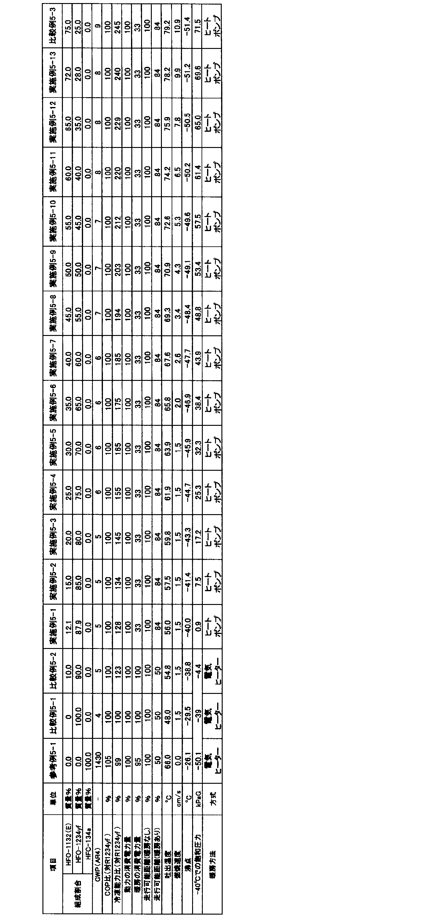
本開示の冷媒2Dは、ジフルオロメタン(HFC-32)、2,3,3,3-テトラフルオロプロペン(HFO-1234yf)、並びに、1,1-ジフルオロエチレン(HFO-1132a)及びテトラフルオロエチレン(FO-1114)の少なくとも一種を含有することを特徴とする。そして、上記特徴を有する本開示の冷媒2Dは、R404A及び/又はR410Aと同等以上の成績係数(COP)と冷凍能力(Cap)とを有し、GWPが十分に小さいという三種の性能を兼ね備えている。
点R(21.80, 3.95, 74.25)、
点S(21.80, 3.05, 75.15)、及び
点T(20.95, 75.30, 3.75)、
の3点をそれぞれ結ぶ線分RS、ST及びTRで囲まれる三角形の範囲内又は前記線分上にあることを特徴とする(図2Aの拡大図中、線分RS、ST及びTRで囲まれる三角形の範囲内又は前記線分上)。
本開示の冷媒2D(第3形態の冷媒2D)は、HFC-32、HFO-1234yf及びHFO-1132aを含み、
前記冷媒において、HFC-32、HFO-1132a及びHFO-1234yfの、これらの総和を基準とする質量%をそれぞれx、y及びzとするとき、HFC-32、HFO-1132a及びHFO-1234yfの総和が100質量%となる3成分組成図において、座標(x, y, z)が、
点L(74.0, 19.9, 6.1)、
点F(49.1, 25.9, 25.0)、
点G(0.0, 48.6, 51.4)、
点O(0.0, 0.0, 100)、及び
点B(73.9, 0.0, 26.1)、
の5点をそれぞれ結ぶ線分LF、FG、GO、OB及びBLで囲まれる図形の範囲内又は前記線分上(但し、線分GO及びOB上を除く)にあり、
前記線分LFは、
座標(y=0.0021x2-0.4975x+45.264)で表わされ、
前記線分FGは、
座標(y=0.0031x2-0.6144x+48.6)で表わされ、且つ、
前記線分GO、OB及びBLが直線であることを特徴とする。
前記冷媒において、HFC-32、HFO-1132a及びHFO-1234yfの、これらの総和を基準とする質量%をそれぞれx、y及びzとするとき、HFC-32、HFO-1132a及びHFO-1234yfの総和が100質量%となる3成分組成図において、座標(x, y, z)が、
点P(59.1, 23.2, 17.7)、
点F(49.1, 25.9, 25.0)、
点G(0.0, 48.6, 51.4)、
点O(0.0, 0.0, 100)及び
点B’(59.0, 0.0, 40.2)、
の5点をそれぞれ結ぶ線分PF、FG、GO、OB’及びB’Pで囲まれる図形の範囲内又は前記線分上(但し、線分GO及びOB’上を除く)にあり、
前記線分PFは、
座標(y=0.0021x2-0.4975x+45.264)で表わされ、
前記線分FGは、
座標(y=0.0031x2-0.6144x+48.6)で表わされ、且つ、
前記線分GO、OB’及びB’Pが直線であることを特徴とする。
前記冷媒において、HFC-32、HFO-1132a及びHFO-1234yfの、これらの総和を基準とする質量%をそれぞれx、y及びzとするとき、HFC-32、HFO-1132a及びHFO-1234yfの総和が100質量%となる3成分組成図において、座標(x, y, z)が、
点M(74.0, 19.5, 6.5)、
点I(62.9, 15.5, 21.6)、
点J(33.5, 0.0, 66.5)、及び
点B(73.9, 0.0, 26.1)、
の4点をそれぞれ結ぶ線分MI、IJ、JB及びBMで囲まれる図形の範囲内又は前記線分上(但し、線分JB上を除く)にあり、
前記線分MIは、
座標(y=0.006x2+1.1837x-35.264)で表わされ、
前記線分IJは、
座標(y=0.0083x2-0.2719x-0.1953)で表わされ、且つ、
前記線分JB及びBMが直線であることを特徴とする。
前記冷媒において、HFC-32、HFO-1132a及びHFO-1234yfの、これらの総和を基準とする質量%をそれぞれx、y及びzとするとき、HFC-32、HFO-1132a及びHFO-1234yfの総和が100質量%となる3成分組成図において、座標(x, y, z)が、
点Q(59.1, 12.7, 28.2)、
点J(33.5, 0.0, 66.5)、及び
点B’(59.0, 0.0, 40.2)、
の3点をそれぞれ結ぶ線分QJ、JB’及びB’Qで囲まれる図形の範囲内又は前記線分上(但し、線分JB’上を除く)にあり、
前記線分QJは、
座標(y=0.0083x2-0.2719x-0.1953)で表わされ、且つ、
前記線分JB’及びB’Qがで直線であることを特徴とする。
前記冷媒において、HFC-32、HFO-1132a及びHFO-1234yfの、これらの総和を基準とする質量%をそれぞれx、y及びzとするとき、HFC-32、HFO-1132a及びHFO-1234yfの総和が100質量%となる3成分組成図において、座標(x, y, z)が、
点Q(59.1, 12.7, 28.2)、
点U(59.0, 5.5, 35.5)、及び
点V(52.5, 8.4, 39.1)、
の3点をそれぞれ結ぶ線分QU、UV及びVQで囲まれる図形の範囲内又は前記線分上にあり、
前記線分VQは、
座標(y=0.0083x2-0.2719x-0.1953)で表わされ、且つ、
前記線分UVは、
座標(y=0.0026x2-0.7385x+39.946)で表わされ
前記線分QUが直線であることを特徴とする。
本開示の冷媒2Dは、上記の特性や効果を損なわない範囲内で、HFC-32、HFO-1234yf、並びに、HFO-1132a及びFO-1114の少なくとも一種に加えて、更に他の追加的な冷媒を含有する混合冷媒であってもよい。この場合、HFC-32、HFO-1234yf、並びに、HFO-1132a及びFO-1114の少なくとも一種の合計量が、本開示の冷媒全体に対して、99.5質量%以上100質量%未満であることが好ましく、99.75質量%以上100質量%未満であることがより好ましく、99.9質量%%以上100質量%未満であることが更に好ましい。 上記追加的な冷媒としては、特に限定されず、この分野で広く使用されている公知の冷媒の中から幅広く選択できる。上記混合冷媒は、上記追加的な冷媒を単独で含んでいてもよいし、上記追加的な冷媒を2種以上を含んでいてもよい。
以下に、実施例を挙げて更に詳細に説明する。ただし、本開示は、これらの実施例に限定されるものではない。
実施例17~87及び比較例2~18(第3形態~第7形態の冷媒2Dに対応)
各実施例及び比較例に示される混合冷媒のGWP、並びに、R404A(R125/143a/R134a=44/52/4重量%)、R410A(R32/R125=50/50重量%)のGWPは、IPCC(Intergovernmental Panel on Climate Change)第4次報告書の値に基づいて評価した。
蒸発温度 -40℃
凝縮温度 40℃
過熱温度 20K
過冷却温度 0K
圧縮機効率 70%
蒸発温度 5℃
凝縮温度 45℃
過熱温度 5K
過冷却温度 5K
圧縮機効率 70%
COP=(冷凍能力又は暖房能力)/消費電力量

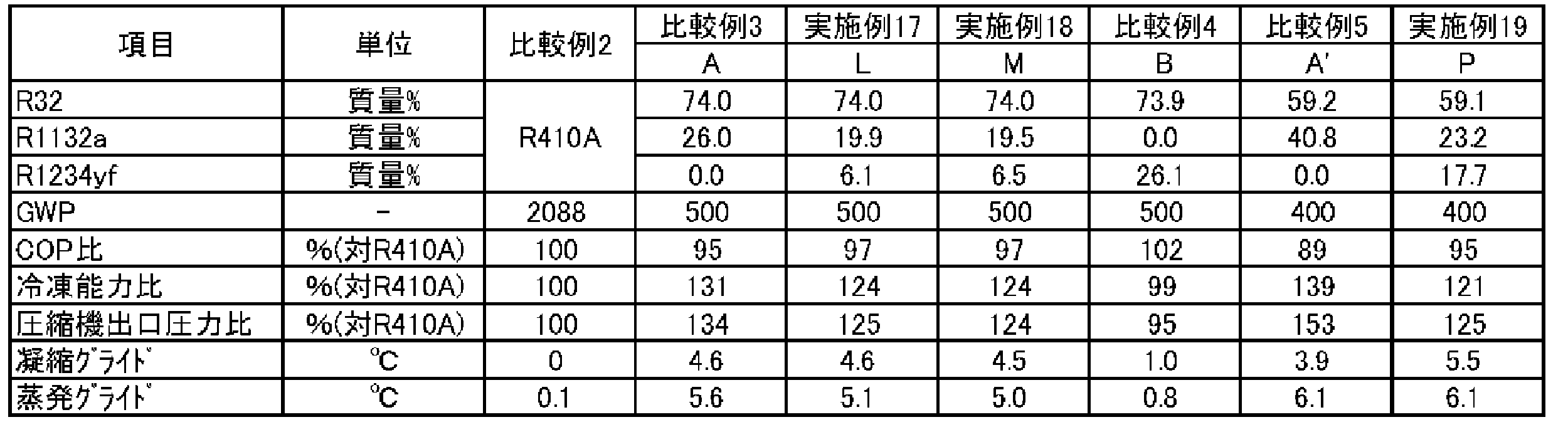
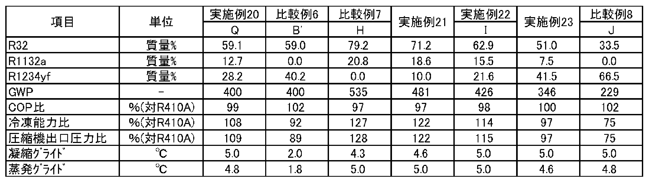
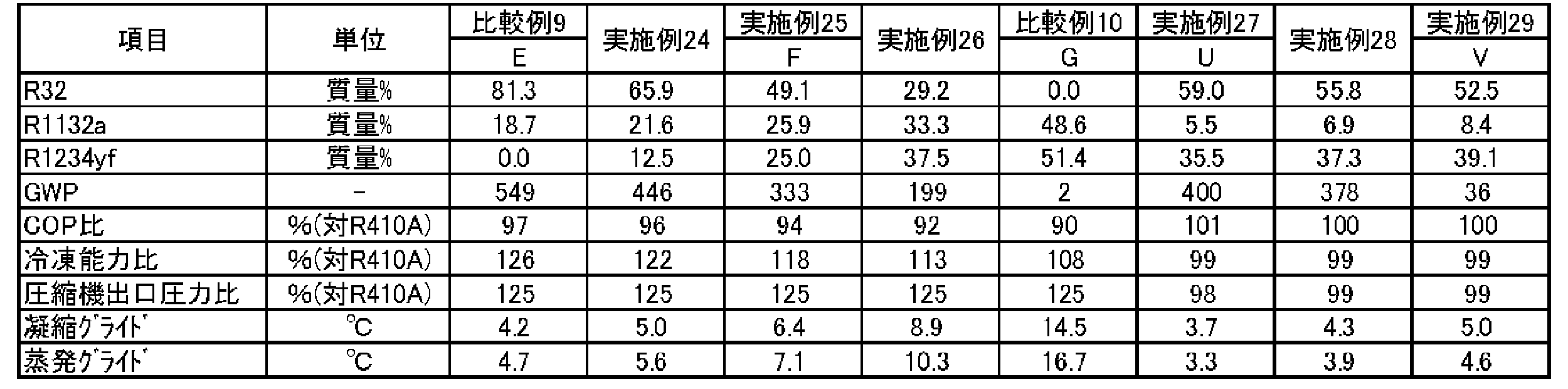
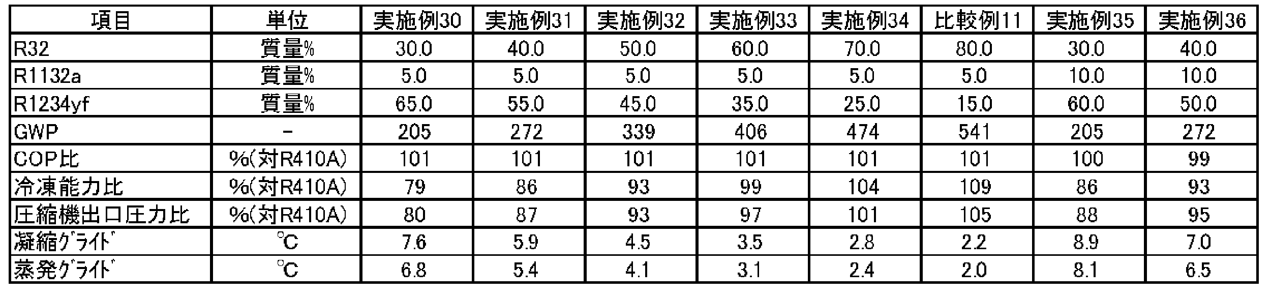


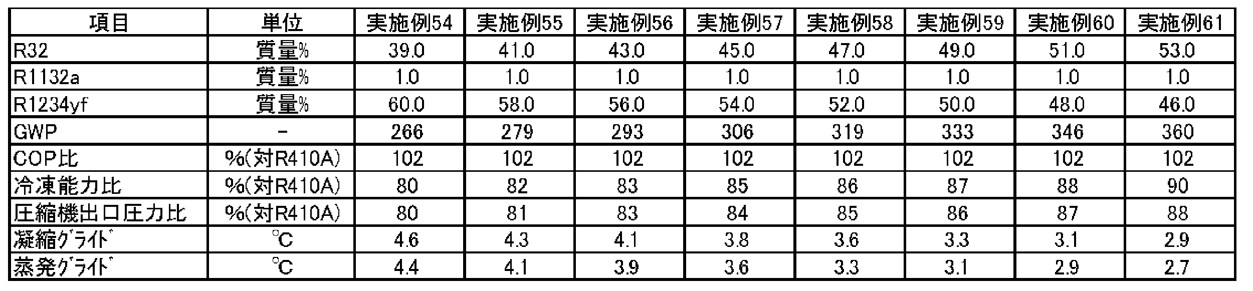
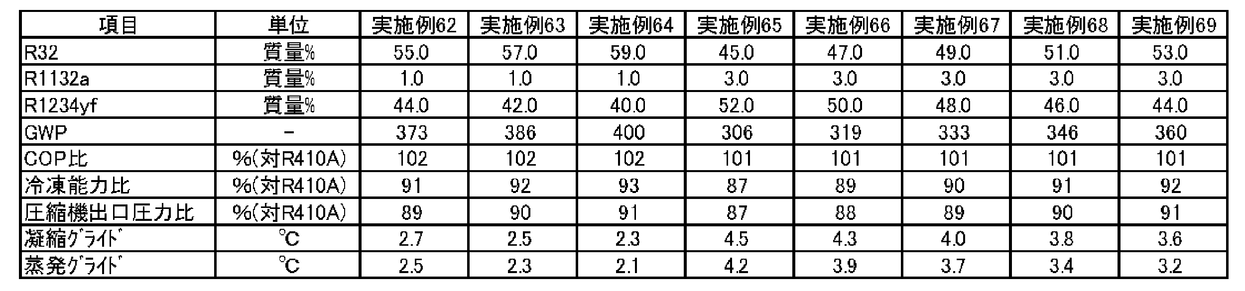
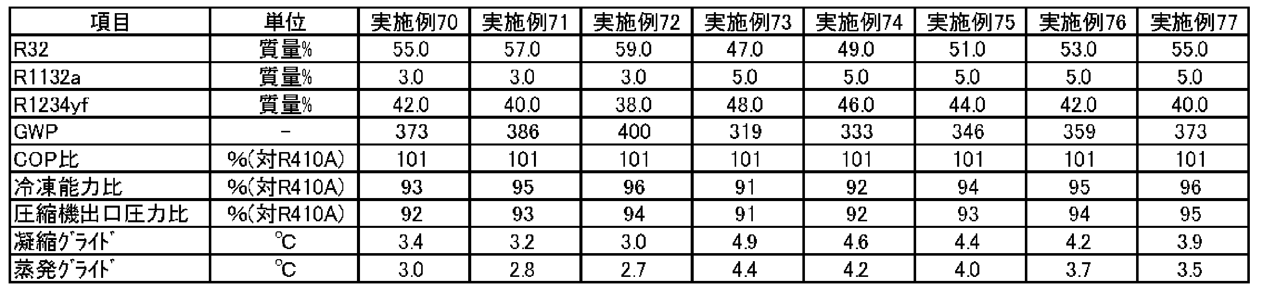
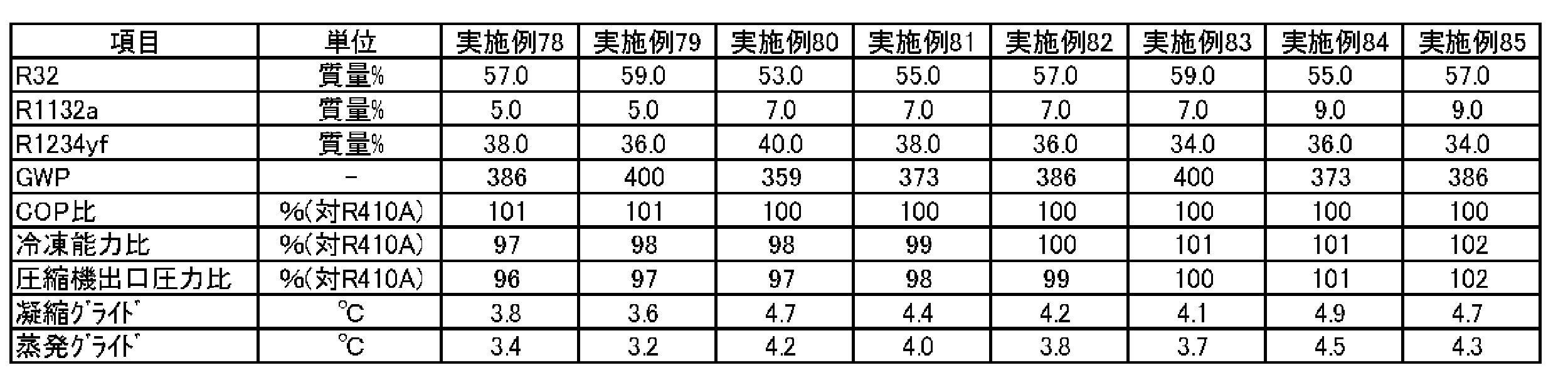

本開示の冷媒2Eは、R32、CO2、R125、R134a及びR1234yfを含有する混合冷媒である。
要件1-1-1)
43.8≧x≧41、かつ0.5≧r≧0.25であるとき、
点A(-0.6902x+43.307, 100-a-x, 0.0)、
点Or=0.25~0.5((-2.2857x+87.314)r2+(1.7143x-55.886)r+(-0.9643x+55.336), (2.2857x-112.91)r2+(-1.7143x+104.69)r+(-0.25x+11.05), 100-a-b-x)、
点Dr=0.25~0.5(0.0, -28.8r2+54.0r+(-x+49.9), 100-b-x)及び
点Q(0.0, 100-x, 0.0)
を結ぶ線分で囲まれる四角形の範囲内又は該線分上にあるか(ただし、線分Dr=0.25~0.5Q及びQA上の点は除く)、又は
1-1-2)
43.8≧x≧41、かつ1.0≧r≧0.5であるとき、
点A(-0.6902x+43.307, 100-a-c, 0.0)、
点Or=0.5~1.0((-0.2857x+8.5143)r2+(0.5x-10.9)+(-0.8571x+52.543), (-0.2857x+4.5143)r2+(0.5x+0.9)r+(-0.7143x+33.586), 100-a-b-x)、
点Dr=0.5~1.0(0.0, (-0.5714x+12.229)r2+(0.8571x-0.3429)r+(-1.2857x+66.814), 100-b-x)及び
点Q(0.0, 100-x, 0.0)
を結ぶ線分で囲まれる四角形の範囲内又は該線分上にあるか(ただし、線分Dr=0.5~1.0Q及びQA上の点は除く)、又は
1-2-1)
46.5≧x≧43.8、かつ0.5≧r≧0.25であるとき、
点A(-0.6902x+43.307, 100-a-x, 0.0)、
点Or=0.25~0.5((1.1852x-64.711)r2+(-0.7407x+51.644)r+(-0.5556x+37.433), (-2.3704x+91.022)r2+(2.0741x-61.244)r+(-0.963x+42.278), 100-a-b-x)、
点Dr=0.25~0.5(0.0, -28.8r2+54.0r+(-x+49.9), 100-b-x)及び
点Q(0.0, 100-x, 0.0)
を結ぶ線分で囲まれる四角形の範囲内又は該線分上にあるか(ただし、線分Dr=0.25~0.5Q及びQA上の点は除く)、又は
要件1-2-2)
46.5≧x≧43、かつ1.0≧r≧0.5であるとき、
点A(-0.6902x+43.307, 100-a-x, 0.0)、
点Or=0.5~1.0((0.2963x-16.978)r2+(-0.3704x+27.222)r+(-0.5185x+37.711), -8.0r2+22.8r+(-0.5185x+25.011), 100-a-b-x)、
点Dr=0.5~1.0(0.0, -12.8r2+37.2r+(-x+54.3), 100-b-x)及び
点Q(0.0, 100-x, 0.0)
を結ぶ線分で囲まれる四角形の範囲内又は該線分上にあるか(ただし、線分Dr=0.5~1.0Q及びQA上の点は除く)、
要件1-3-1)
50≧x≧46.5、かつ0.5≧r≧0.25であるとき、
点A(-0.6902x+43.307, 100-a-x, 0.0)、
点Or=0.25~0.5(-9.6r2+17.2r+(-0.6571x+42.157), -19.2r2+(0.2286x+24.571)r+(-0.6286x+26.729), 100-a-b-x)、
点Dr=0.25~0.5(0.0, (0.9143x-71.314)r2+(-0.5714x+80.571)+(-0.9143x+45.914), 100-b-x)及び
点Q(0.0, 100-x, 0.0)
を結ぶ線分で囲まれる四角形の範囲内又は該線分上にあるか(ただし、線分Dr=0.25~0.5Q及びQA上の点は除く)、又は
1-3-2)
50≧x≧46.5、かつ1.0≧r≧0.5であるとき、
点A(-0.6902x+43.307, 100-a-x, 0.0)、
点Or=0.5~1.0((-0.2286x+7.4286)r2+(0.4x-8.6)r+(-0.8x+50.8), (0.2286x-18.629)r2+(-0.2857x+36.086)r+(-0.4286x+20.829), 100-a-b-x)、
点Dr=0.5~1.0(0.0, (0.2286x-23.429)r2+(-0.4x+55.8)r+(-0.8286x+46.329), 100-b-x)及び
点Q(0.0, 100-x, 0.0)
を結ぶ線分で囲まれる四角形の範囲内又は該線分上にある(ただし、線分Dr=0.5~1.0Q及びQA上の点は除く)。
要件2-1-1)
43.8≧x≧41、かつ0.5≧r≧0.25であるとき、
点Fr=0.25~0.5(0.0, (-1.1429x+37.257)r2+(1.2857x-38.714)r-(-1.7143x+106.89), 100-b-x)、
点Pr=0.25~0.5((-1.1429x+34.057)r2+(1.0x-21.0)r+(-0.4643x+27.636), (2.2857x-119.31)r2+(-2.0x+122.0)r+(-0.3929x+19.907), 100-a-b-x)及び
点Dr=0.25~0.5(0.0, -28.8r2+54.0r+(-x+49.9), 100-b-x)
を結ぶ線分で囲まれる三角形の範囲内又は該線分上にあるか(ただし、線分Dr=0.25~0.5Fr=0.25~0.5上の点は除く)、又は
2-1-2)43.8≧x≧41、かつ1.0≧r≧0.5であるとき、
点Fr=0.5~1.0(0.0, (3.7143x-159.49)r2+(-5.0714x+222.53)r+(0.25x+25.45), 100-b-x)、
点Pr=0.5~1.0((3.4286x-138.17)r2+(-5.4286x+203.57)+(1.6071x-41.593), (-2.8571x+106.74)r2+(4.5714x-143.63)r+(-2.3929x+96.027), 100-a-b-x)及び
点Dr=0.5~1.0(0.0, (-0.5714x+12.229)r2+(0.8571x-0.3429)r+(-1.2857x+66.814), 100-b-x)
を結ぶ線分で囲まれる三角形の範囲内又は該線分上にあるか(ただし、線分Dr=0.5~1.0Fr=0.5~1.0上の点は除く)、又は
2-2-1)46.5≧x≧43、かつ0.5≧r≧0.25であるとき、
点Fr=0.25~0.5(0.0, (9.4815x-428.09)r2+(-7.1111x+329.07)r+(-0.2593x+43.156), 100-b-x)、
点Pr=0.25~0.5((-8.2963x+347.38)r2+(4.8889x-191.33)r+(-0.963x+49.478), (7.1111x-330.67)r2+(-4.1481x+216.09)r+(-0.2593x+14.056), 100-a-b-x)及び
点Dr=0.25~0.5(0.0, -28.8r2+54.0r+(-x+49.9), 100-b-x)
を結ぶ線分で囲まれる三角形の範囲内又は該線分上にあるか(ただし、線分Dr=0.25~0.5Fr=0.25~0.5上の点は除く)、又は
2-2-2)46.5≧x≧43、かつ1.0≧r≧0.5であるとき、
点Fr=0.5~1.0(0.0, (-4.7407x+210.84)r2+(6.963x-304.58)r+(-3.7407x+200.24), 100-b-x)、
点Pr=0.5~1.0((0.2963x-0.9778)r2+(0.2222x-43.933)r+(-0.7778x+62.867), (-0.2963x-5.4222)r2+(-0.0741x+59.844)r+(-0.4444x+10.867), 100-a-b-x)及び
点Dr=0.5~1.0(0.0, -12.8r2+37.2r+(-x+54.3), 100-b-x)
を結ぶ線分で囲まれる三角形の範囲内又は該線分上にあるか(ただし、線分Dr=0.5~1.0Fr=0.5~1.0上の点は除く)、又は
2-3-1)50≧x≧46.5、かつ0.37≧r≧0.25であるとき、
点Fr=0.25~0.37(0.0, (-35.714x+1744.0)r2+(23.333x-1128.3)r+(-5.144x+276.32), 100-b-x)、
点Pr=0.25~0.37((11.905x-595.24)r2+(-7.6189x+392.61)r+(0.9322x-39.027), (-27.778x+1305.6)r2+(17.46x-796.35)r+(-3.5147x+166.48),100-a-b-x)及び
点Dr=0.25~0.37(0.0, (0.9143x-71.314)r2+(-0.5714x+80.571)+(-0.9143x+45.914), 100-b-x)
を結ぶ線分で囲まれる三角形の範囲内又は該線分上にあるか(ただし、線分Dr=0.25~0.37Fr=0.25~0.37上の点は除く)、又は
2-3-2)50≧x≧46.5、かつ1.0≧r≧0.5であるとき、
点Fr=0.5~1.0(0.0, (2.2857x-115.89)r2+(-3.0857x+162.69)r+(-0.3714x+43.571), 100-b-x)、
点Pr=0.5~1.0((-3.2x+161.6)r2+(4.4571x-240.86)r+(-2.0857x+123.69), (2.5143x-136.11)r2+(-3.3714x+213.17)r+(0.5429x-35.043), 100-a-b-x)及び
点Dr=0.5~1.0(0.0, (0.2286x-23.429)r2+(-0.4x+55.8)r+(-0.8286x+46.329), 100-b-x)
を結ぶ線分で囲まれる三角形の範囲内又は該線分上にある(ただし、線分Dr=0.5~1.0Fr=0.5~1.0上の点は除く)。
以下に、実施例を挙げてさらに詳細に説明する。ただし、本開示は、これらの実施例に限定されるものではない。
1.WCF不燃限界、及びASHRAE不燃限界(WCF&WCFF不燃)の計算
R32、CO2、R125、R134a及びR1234yfのみからなる混合冷媒の組成は、以下のようにして表わす。すなわち、R32、CO2、R125、R134a及びR1234yfの総和を基準とする、R32の質量%をa、CO2の質量%をb、R125の質量%をc1、R134aの質量%をc2、R125及びR134aの合計の質量%をc、R1234yfの質量%をxとし、c1/(c1+c2)をrとする場合、R32が(100-x)質量%の点と、CO2が(100-x)質量%の点と、R125及びR134aの合計が(100-x)質量%の点とを頂点とする3成分組成図における座標(a,b,c)により、この混合冷媒の組成を特定する。
2元混合冷媒の不燃限界は、ASTM E681-2009に基づく燃焼試験の測定装置(図2E)及び測定方法に基づいて求めた。
試験容器:280 mmφ球形(内容積:12リットル)
試験温度: 60℃±3℃
圧力 :101.3 kPa±0.7 kPa
水分 :乾燥空気1 gにつき0.0088 g±0.0005 g
2元冷媒組成物/空気混合比:1 vol.%刻み±0.2 vol.%
2元冷媒組成物混合: ±0.1 質量%
点火方法:交流放電、電圧15kV、電流30mA、ネオン変圧器
電極間隔:6.4 mm (1/4 inch)
スパーク:0.4 秒 ±0.05 秒
判定基準:
・着火点を中心に90度より火炎が広がった場合 = 燃焼(伝播)
・着火点を中心に90度以下の火炎の広がりだった場合= 火炎伝播なし(不燃)
表232に記載の可燃性冷媒及び不燃性冷媒の組合せについてそれぞれ試験を行った。可燃性冷媒に対して不燃性冷媒を段階的に添加していき、各段階において燃焼試験を行った。
その結果、可燃性冷媒R32と不燃性冷媒R134aとの混合冷媒では、R32=43.0質量%、R134a=57.0質量%から火炎伝播は認められなくなり、この組成を不燃限界とした。また、可燃性冷媒R32と不燃性冷媒R125では、R32=63.0質量%、R125=37.0質量%、可燃性冷媒R32と不燃性冷媒2CO2では、R32=43.5質量%、CO2=56.5質量%、可燃性冷媒1234yfと不燃性冷媒R134aでは、1234yf=62.0質量%、R134a=38.0質量%、可燃性冷媒1234yfと不燃性冷媒R125では、1234yf=79.0質量%、R125=21.0質量%、可燃性冷媒1234yfと不燃性冷媒2CO2では、1234yf=63.0質量%、CO2=37.0質量%からそれぞれ火炎伝播は認められなくなり、これらの組成を不燃限界とした。表232に結果をまとめた。
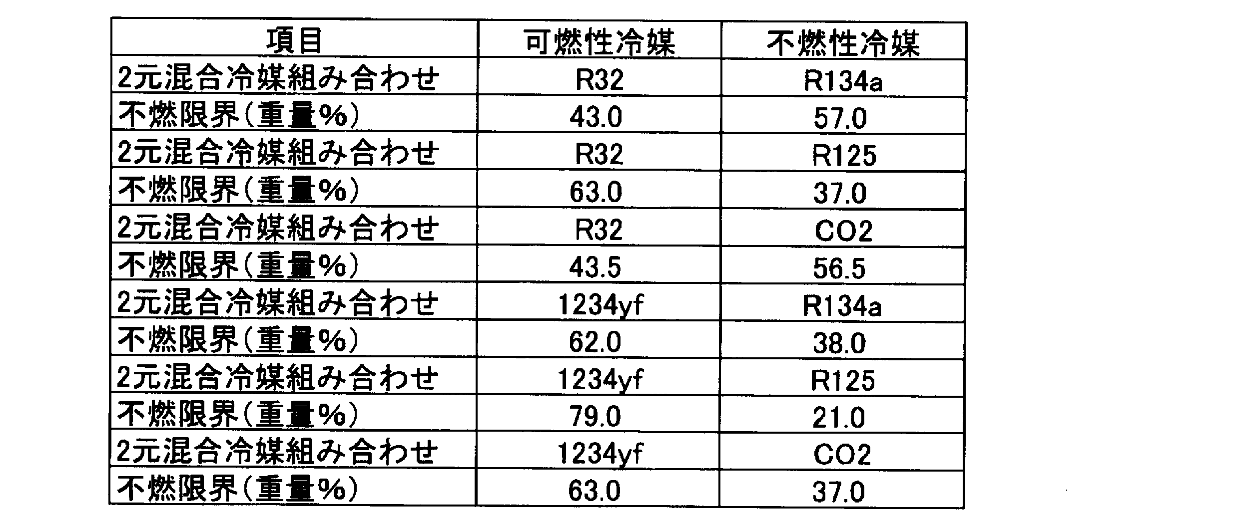
a+b=59質量%とし、以下の手順で混合組成が不燃限界組成になっているかどうかを調べた。
(2) R32換算不燃冷媒濃度=R125濃度×(63/37)+R134a濃度×(43/57)+CO2濃度×(43.5/56.5)
ここで、R32換算不燃冷媒組成-R32換算可燃冷媒組成の値がプラスで最小値を示す値を計算上の不燃限界組成とした。表233に計算結果を示すが、点A(15.0,44.0,0)が計算上の不燃限界組成であった。

a+c=29質量%とし、前記と同様の手順でこの条件での不燃限界組成を求め、その結果を表234に示す。

a+c=44質量%とし、前記と同様の手順でこの条件での不燃限界組成を求め、その結果を表235に示す。

a+c=59質量%とし、前記と同様の手順でこの条件での不燃限界組成を求め、その結果を表236に示す。

表233で示す組成、
可燃限界組成-1-1)(R32/CO2/R125/R134a)=(15.1/43.9/0.0/0.0)、
不燃限界組成-1-2)(R32/CO2/R125/R134a)=(15.0/44.0/0.0/0.0)、
表235で示す組成、
可燃限界組成-2-1)(R32/CO2/R125/R134a)=(18.3/15.0/6.4/19.3)、
不燃限界組成-2-2)(R32/CO2/R125/R134a)=(18.2/15.0/6.5/19.3)、
を[1]で示したASTM E681に従って燃焼試験を行ったところ、組成-1-1)、組成-2-1)は火炎伝播が認められ、組成1-1-2)、組成-2-2)は火炎伝播は認められなかった。従って、2元混合冷媒の不燃限界から求めた混合冷媒の不燃限界は実際の不燃限界を示しているといえる。
5) x=41質量%、r=0.25、a=0質量%の場合 点Br=0.25(0.0,b,c(c1+c2))
Refleakで貯蔵/輸送時の漏洩試験、装置からの漏洩試験、漏洩・再充填試験を行なったところ、貯蔵/輸送時の漏洩条件が一番燃えやすい条件であり、かつ、-40℃での漏洩が一番燃えやすい条件であった。従って、ASHRAE不燃限界は、貯蔵/輸送時で-40℃での漏洩試験を、Refleakでの漏洩シミューレーションを行い以下の手順で求めた。表237は漏洩シミュレーションでの可燃/不燃の限界となる代表値を示す。初期組成が(0.0,39.5,19.5(4.9+14.6))のときに輸送及び貯蔵条件では-40℃、52%放出時に大気圧になり、その時の液側の濃度はx=67.0質量%で(0.0,2.5,30.5(6.1+24.4))であり、前記した不燃判定では大気圧条件で不燃となる限界であった。一方、初期組成が(0.0,39.6,19.4(4.9+14.5))では-40℃、52%放出時に大気圧になり、その時の液側濃度はx=67.1%で(0.0,2.6,30.3(6.1+24.2))であり、前記した不燃判定では可燃であった。従って、初期組成が(0.0,39.5,19.5(4.9+14.6))をWCF組成とした場合に、WCF組成、WCFF組成ともに計算上不燃と判断されるので、(0.0,39.5,19.5(4.9+14.6))がASHRAE不燃限界組成である。

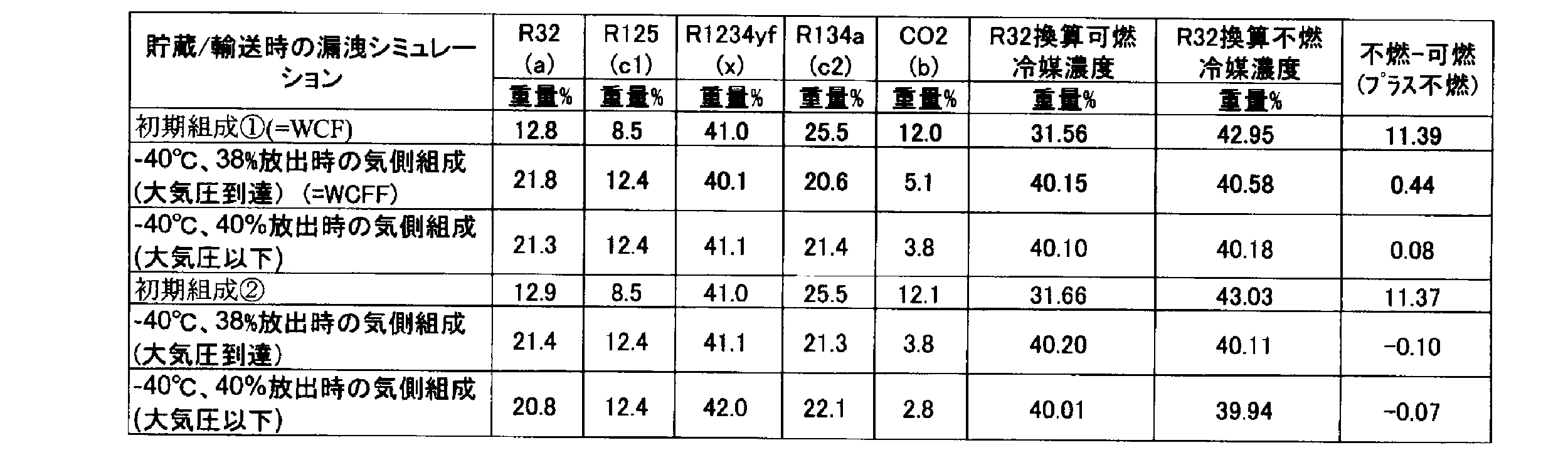
上記と同様に調べた結果を表239に示す。

上記と同様に調べた結果を表240に示す。
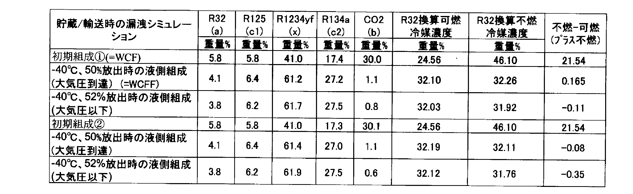
下記組成を[1]で示したASTM E681に従って燃焼試験を行ったところ、組成-3-1)、組成-4-1)、及び組成5-1)は火炎伝播が認められず、組成-3-2)、組成-4-2)、及び組成-5-2)は火炎伝播が認められた。従って、表237,238,239の計算で示したASHRAE不燃限界は実際の不燃限界を示しているといえる。
組成3-1)
x=R1234yf=41.0質量%、(R32/CO2/R125/R134a)=(0.0/39.5/4.9/14.6)の-40℃、52%放出時の液側組成、x=67.0%、(R32/CO2/R125/R134a)=(0.0/2.5/6.1/24.4)
組成3-2)
x=R1234yf=41.0質量%、(R32/CO2/R125/R134a)=(0.0/39.6/4.9/14.5)の-40℃、52%放出時の液側組成、x=67.1%、(R32/CO2/R125/R134a)=(0.0/2.6/6.1/24.2)
組成4-1)
x=R1234yf=41.0質量%、(R32/CO2/R125/R134a)=(12.8/12.2/8.5/25.5)の-40℃、38%放出時の気側組成、x=40.1%、(R32/CO2/R125/R134a)=(21.8/5.1/12.4/20.6)
組成4-2)
x=R1234yf=41.0質量%、(R32/CO2/R125/R134a)=(12.9/12.1/8.5/25.5)の-40℃、38%放出時の気側組成、x=41.1%、(R32/CO2/R125/R134a)=(21.4/3.8/12.4/21.3)
組成5-1)
x=R1234yf=41.0質量%、(R32/CO2/R125/R134a)=(5.8/30.0/5.8/17.4)の-40℃、50%放出時の液側組成、x=61.2%、(R32/CO2/R125/R134a)=(4.1/1.1/6.4/27.2)
組成5-2)
x=R1234yf=41.0質量%、(R32/CO2/R125/R134a)=(5.8/30.1/5.8/17.3)の-40℃、50%放出時の液側組成、x=61.4%、(R32/CO2/R125/R134a)=(4.1/1.1/6.4/27.0)
図2Oには表237,238,239,240で示したASHRAE不燃限界点と点Fr=0.25 と点Pr=0.25より結んだ直線Fr=0.25 Pr=0.25を示す。ASHRAE不燃限界点は、図2Oで示すように直線Fr=0.25Pr=0.25より可燃冷媒R32側にあるが、安全率も見込んでここでは点Fr=0.25、点Pr=0.25を求めることで得られる直線Fr=0.25Pr=0.25をASHRAE不燃限界線とする。
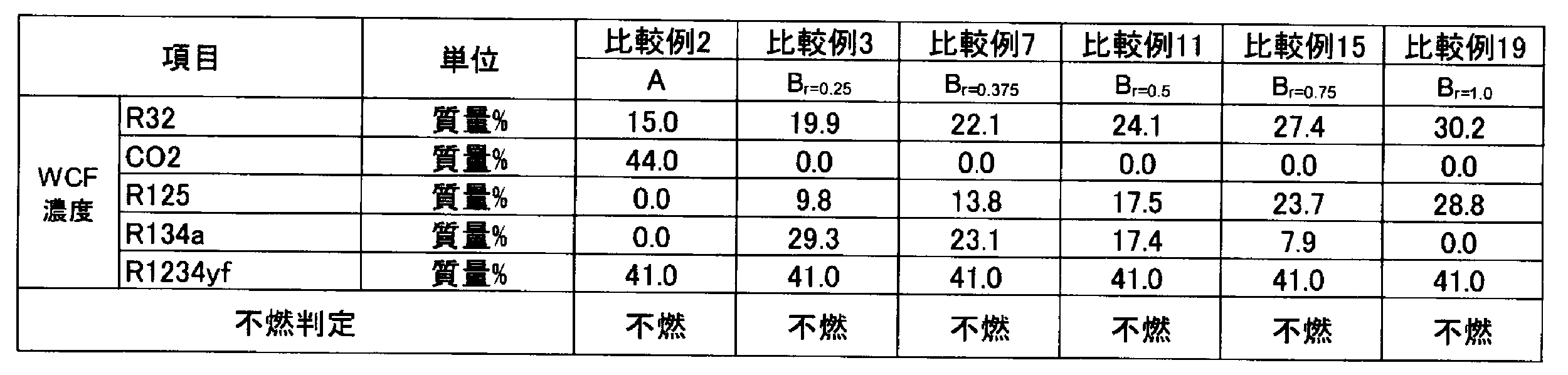
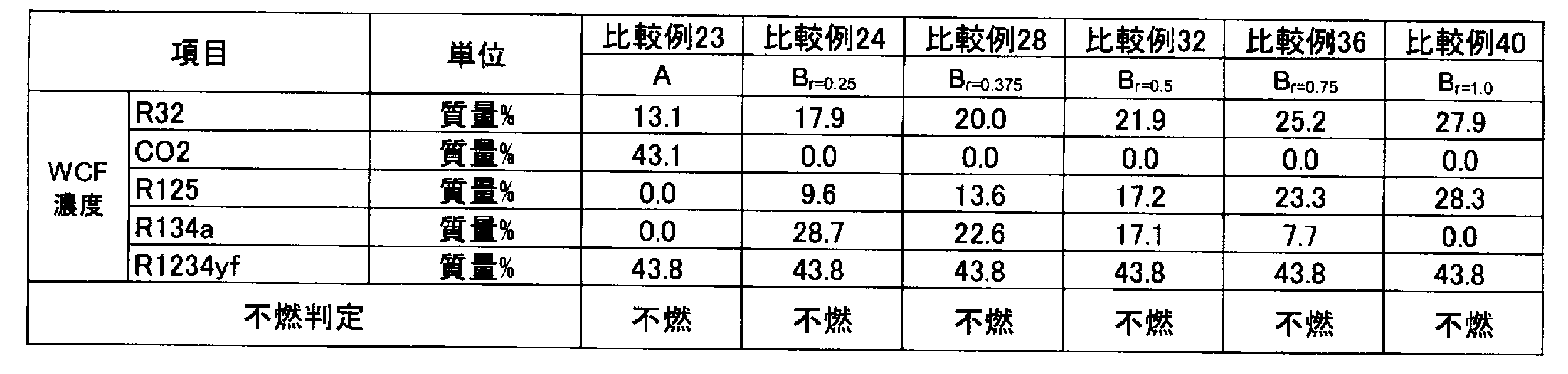
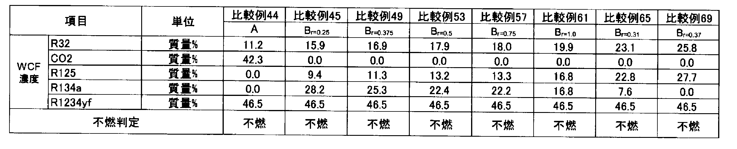

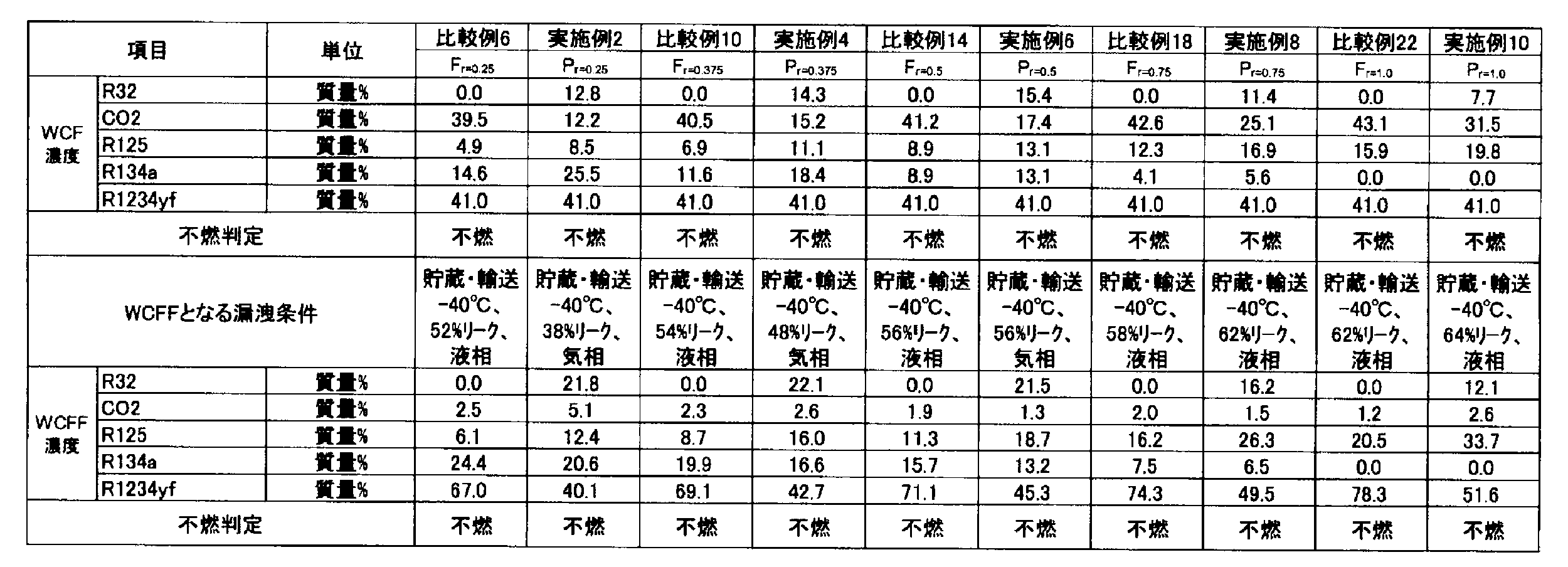

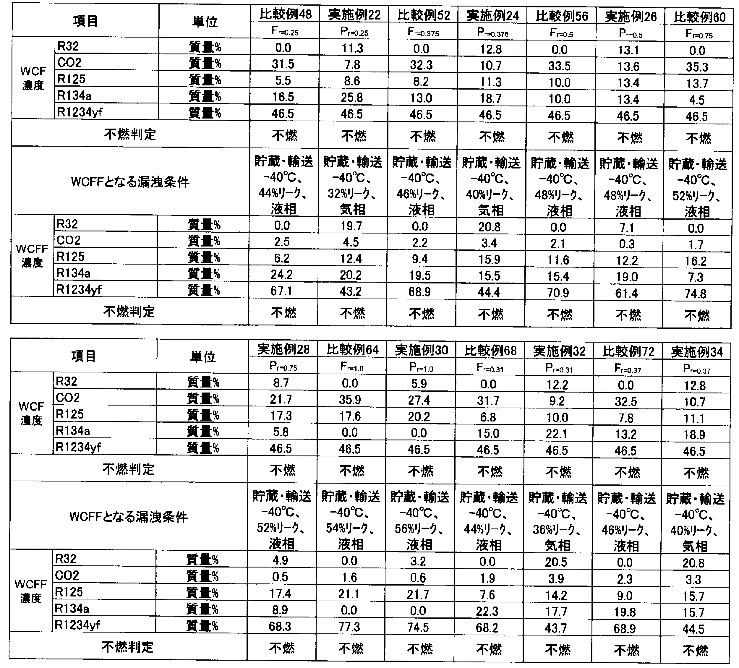

R410A、R32、R125、R1234yf、R134a及びCO2の混合物を含有する組成物のGWPは、IPCC(Intergovernmental Panel on Climate Change)第4次報告書の値に基づいて評価した。また、R410A 並びにR32、R125、R1234yf、R134a及びCO2の混合物を含有する組成物の冷凍能力は、National Institute of Science and Technology(NIST) Reference Fluid Thermodynamic and Transport Properties Database(Refprop 9.0)を使い、下記条件で混合冷媒の冷凍サイクル理論計算を実施することにより求めた。
蒸発温度 -10℃
凝縮温度 45℃
過熱温度 20K
過冷却温度 5K
圧縮機効率 70%
また、これらの結果をもとに算出したGWP、COP及び冷凍能力を表249~280に示す。なお、COP及び冷凍能力については、R410Aに対する割合を示す。
COP =(冷凍能力又は暖房能力)/消費電力量
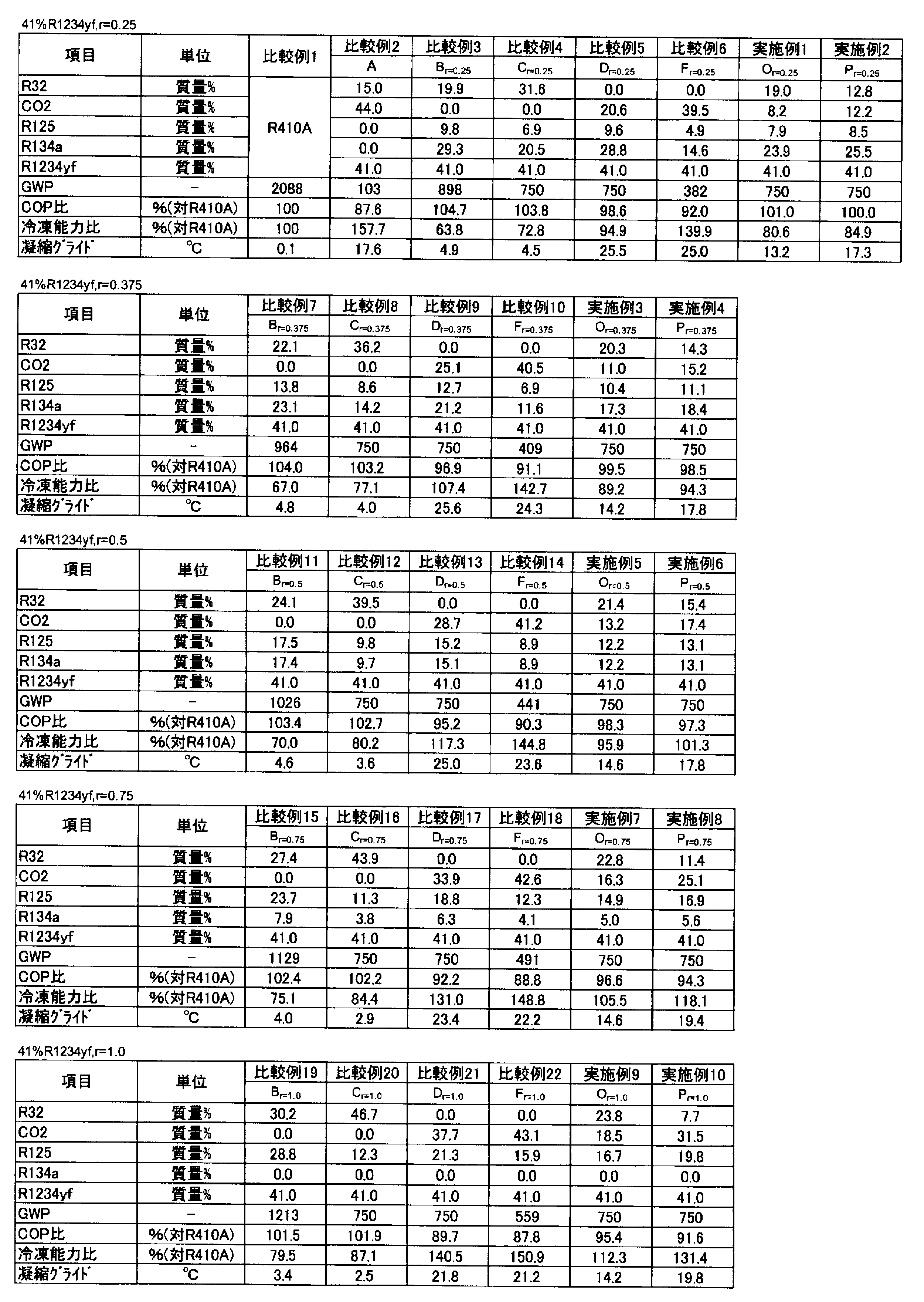


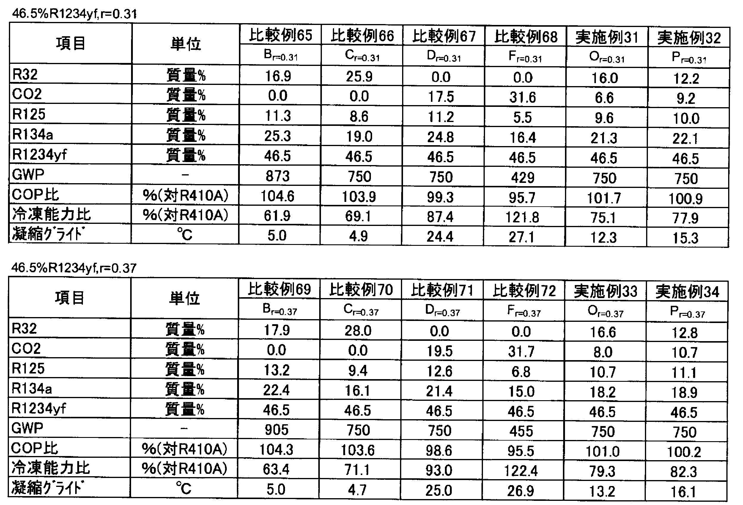
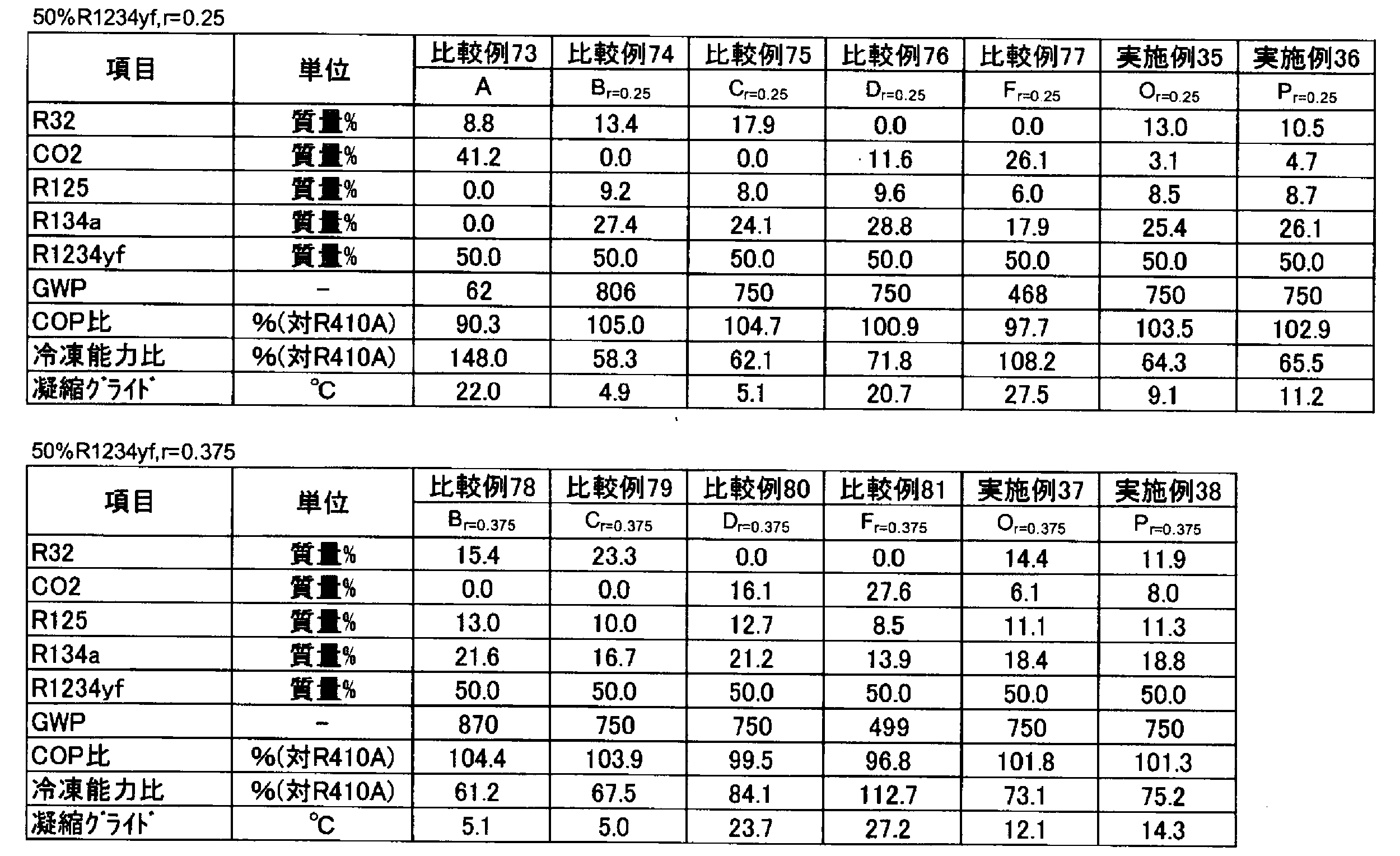
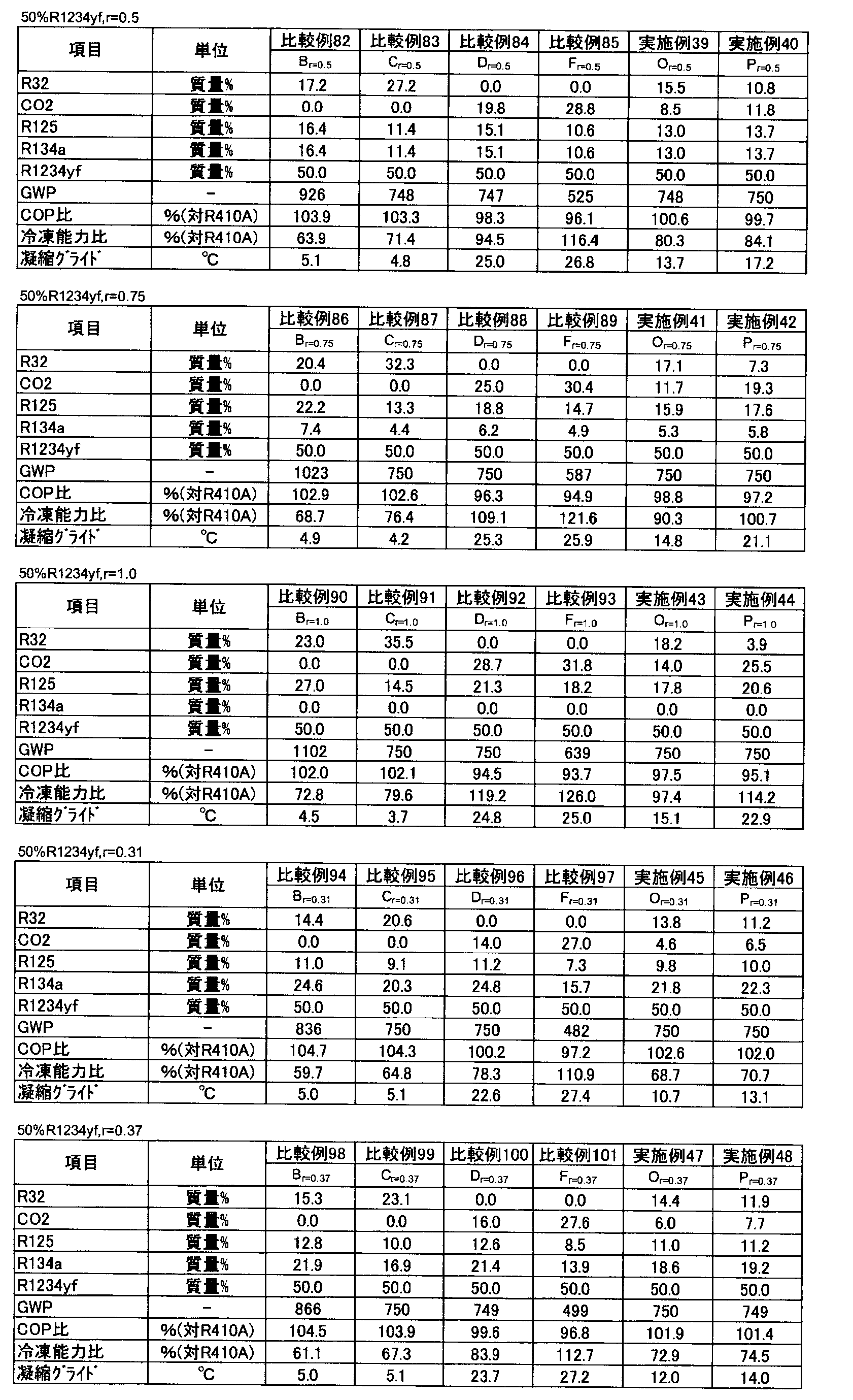

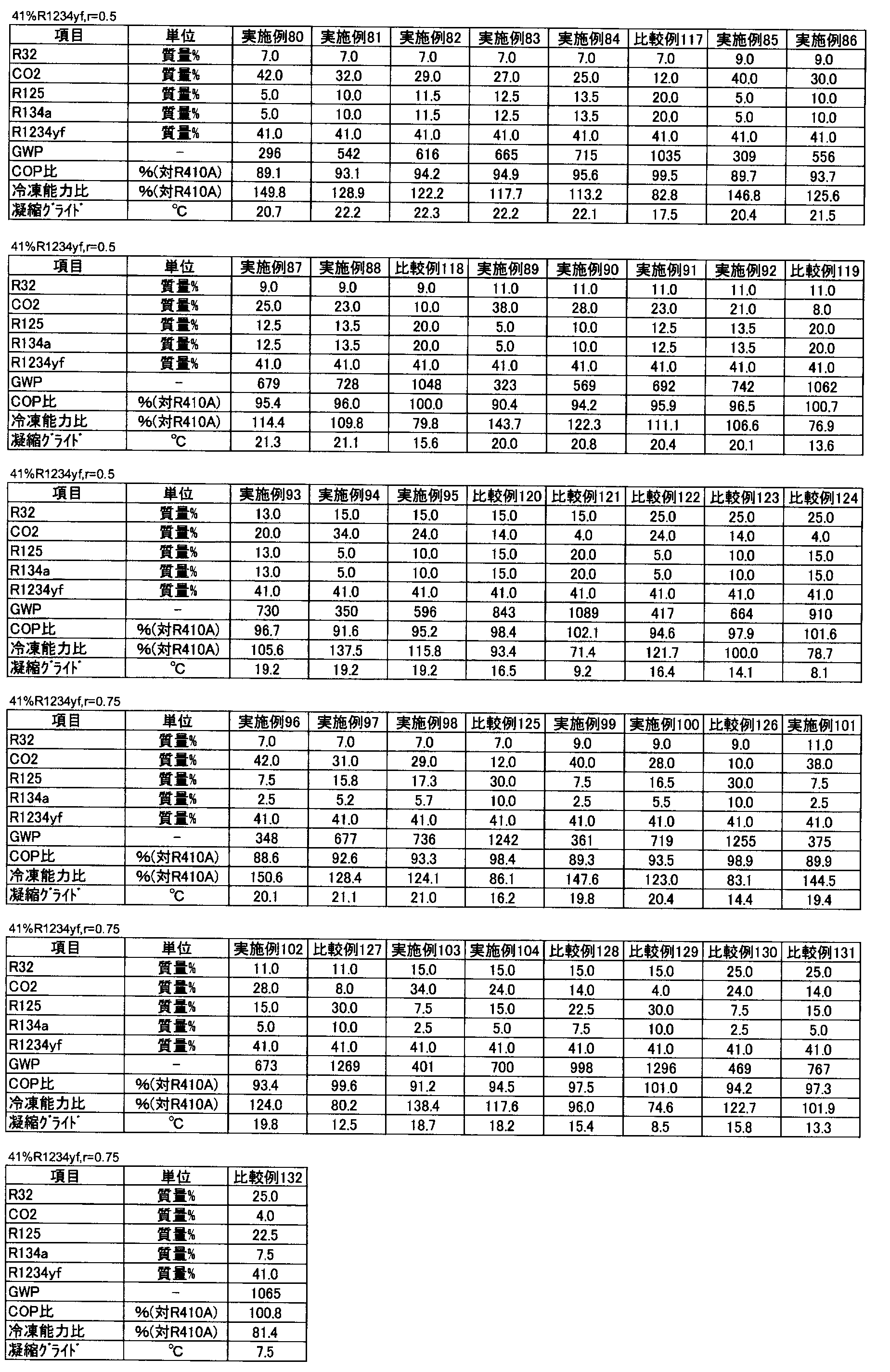
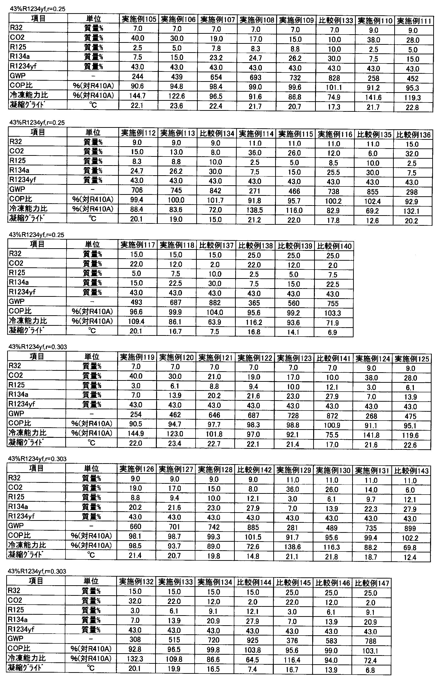
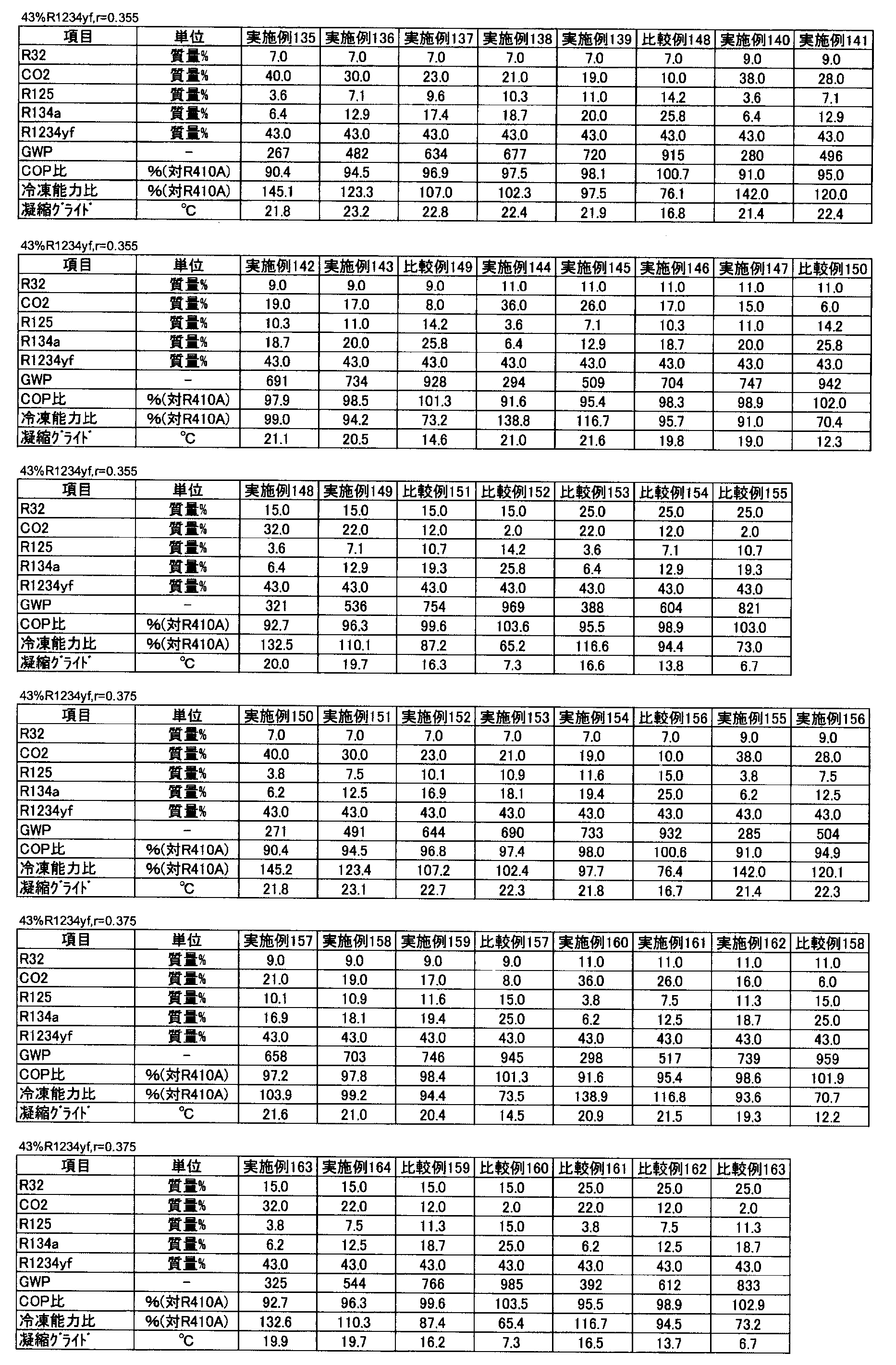

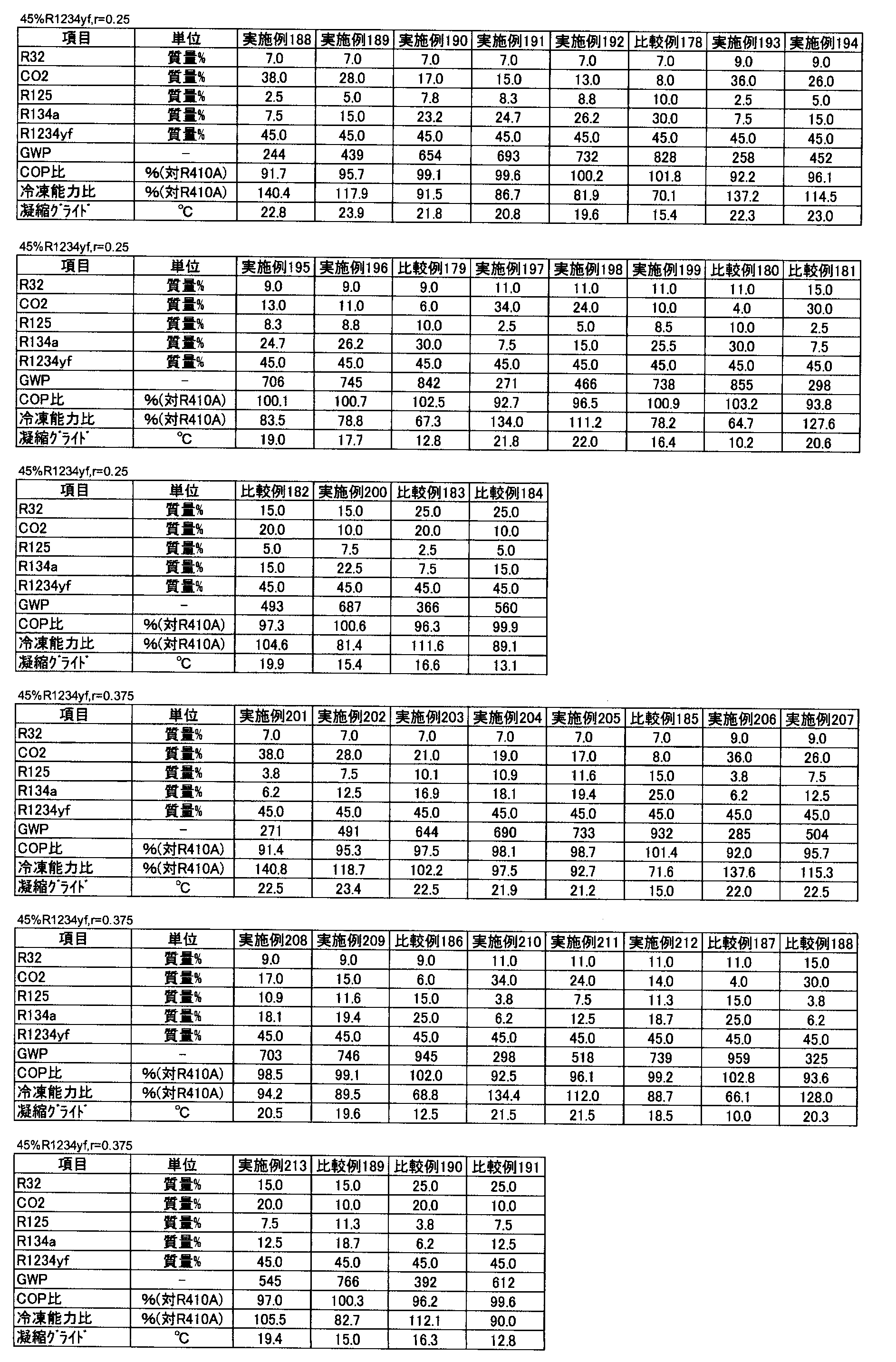

点A
上記のようにして明らかになった、点Aの4種の組成に基づいて、以下のようにして最小二乗法によりR1234yfの割合(x)の関数として点Aの座標の近似式を求めた。すなわち、点Aの座標(a,b,c)=(-0.6902x+43.307, 100-a-x, 0.0)となることが判った。

また、上記のようにして明らかになった、点Brの組成に基づいて、以下のようにして最小二乗法と計算によりr、及びR1234yfの割合(x)の関数として点Brの座標の近似式を求めた。
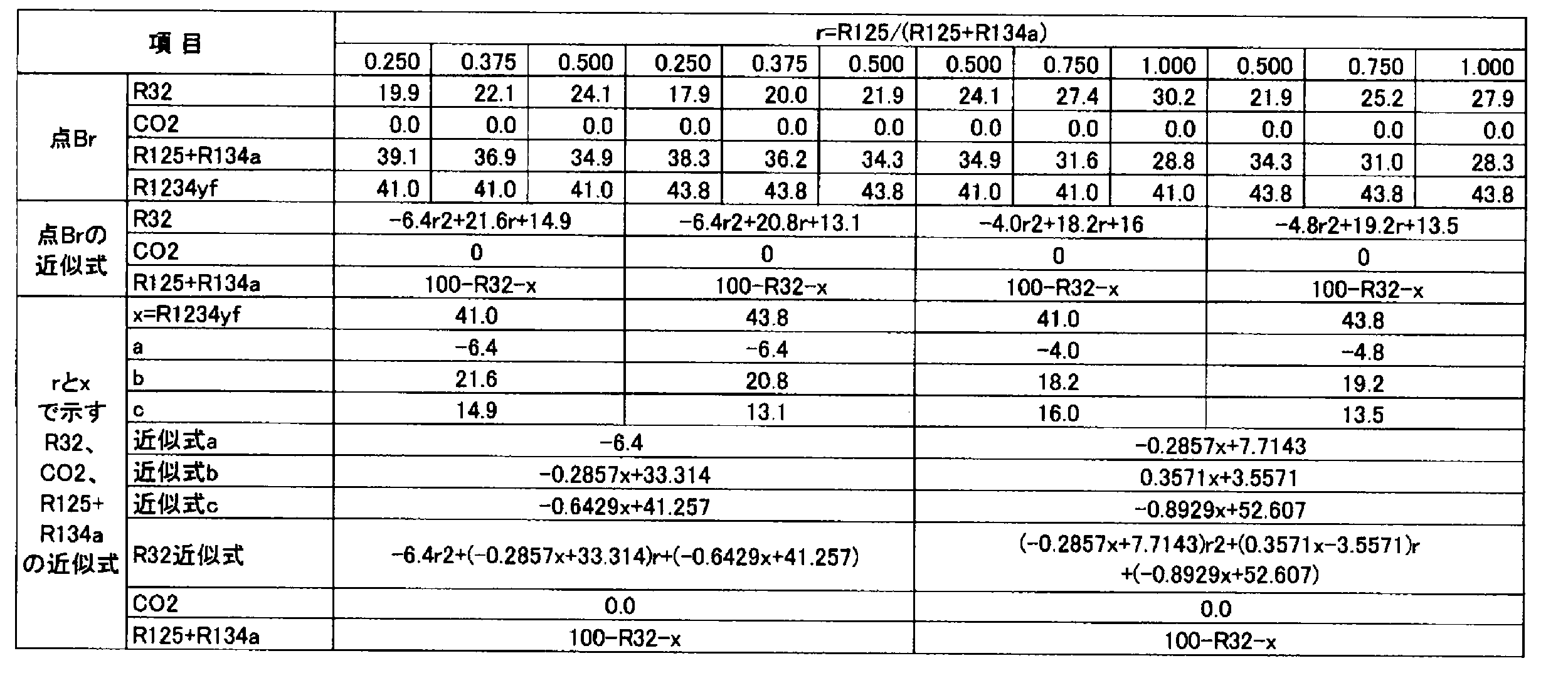
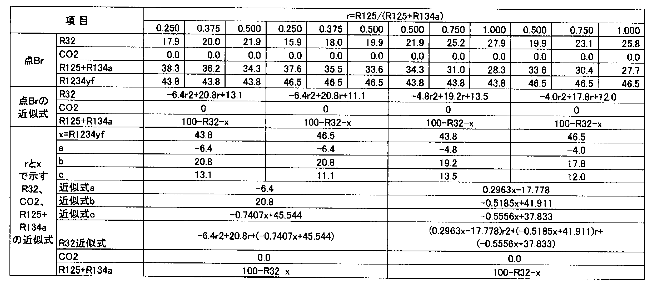

また、上記のようにして明らかになった、点Cr、点Drの組成に基づいて、以下のようにして最小二乗法と計算によりr、及びR1234yfの割合(x)の関数として点Cr、点Dr座標の近似式を求めた。
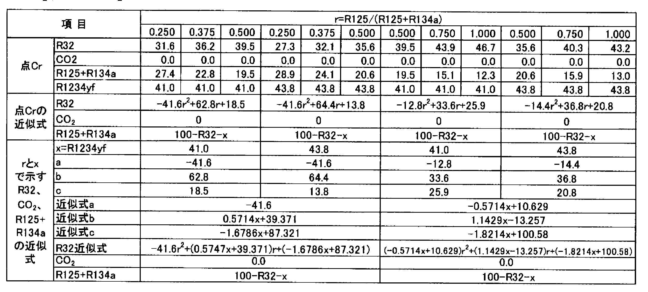

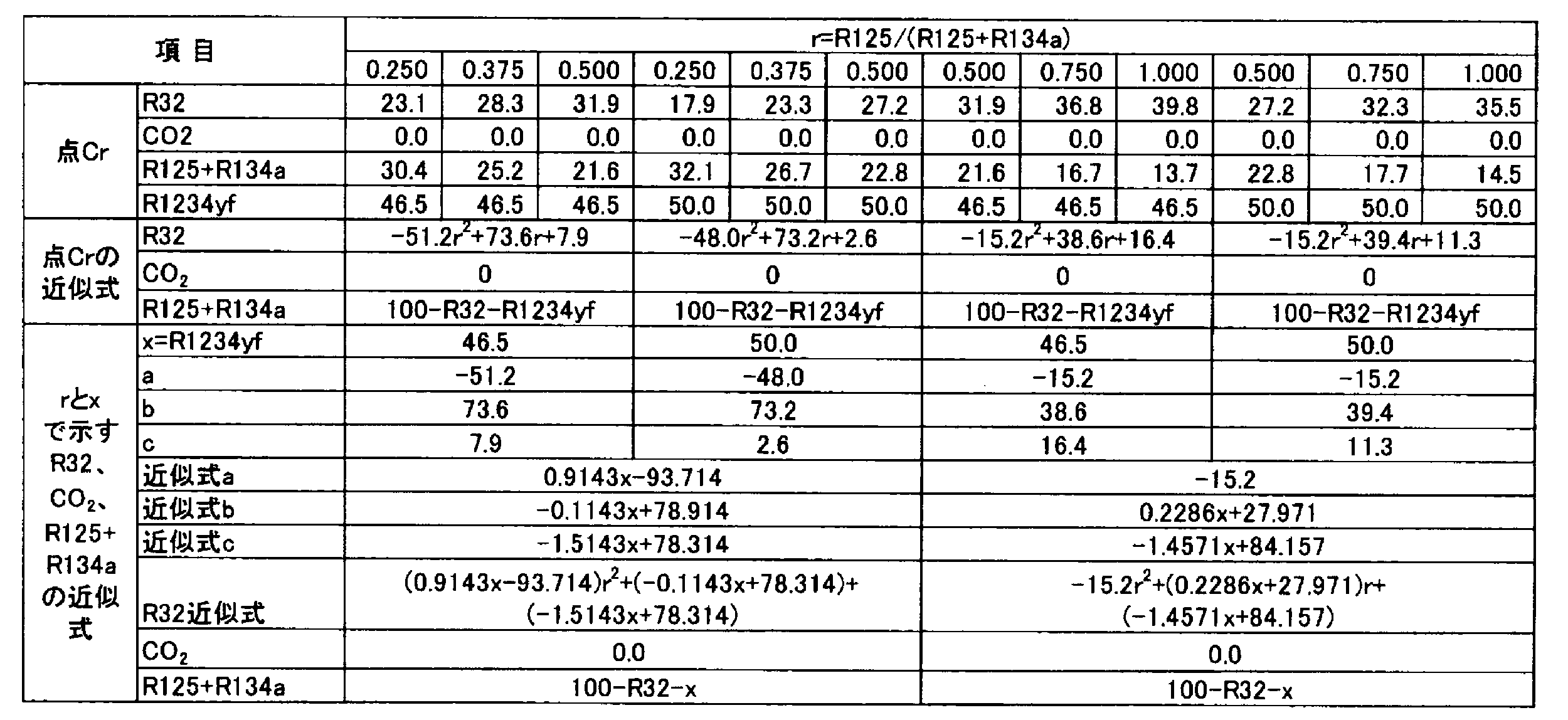

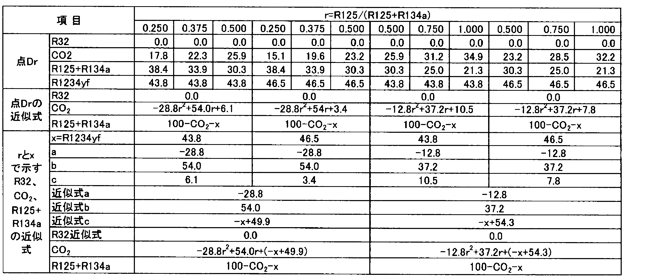
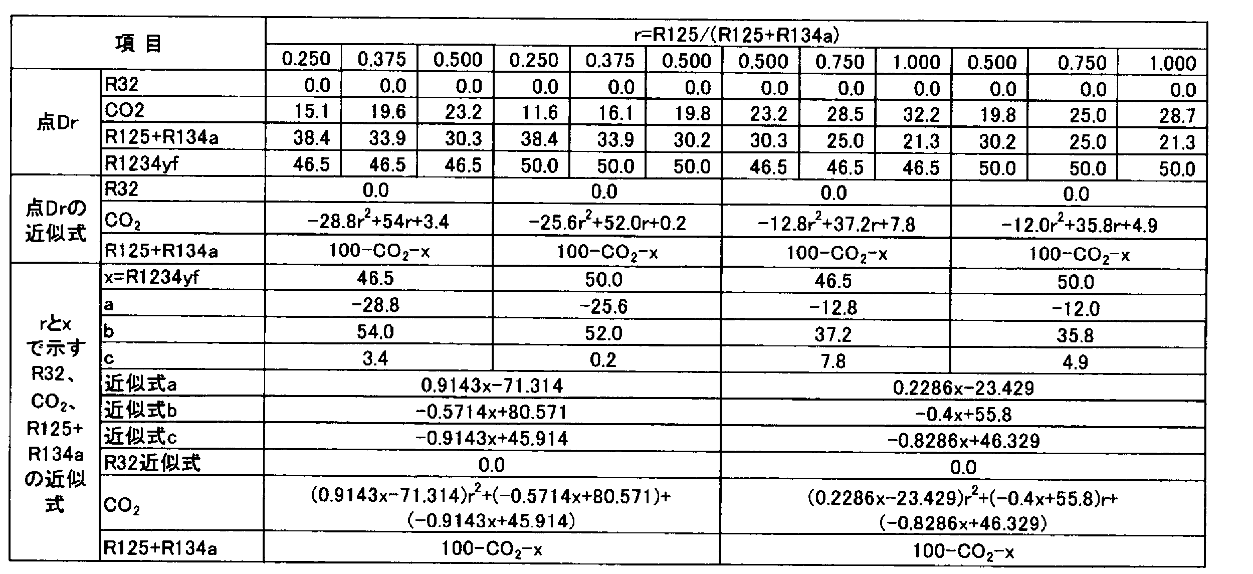
線分ABrと線分CrDrとの交点であるOrの各点は実施例及び比較例で示しているが、Orの組成に基づいて、以下のようにして最小二乗法と計算によりr、及びR1234yfの割合(x)の関数として点Or座標の近似式を求めた。


点Frと点Prの各点は実施例及び比較例で示しているが、各組成に基づいて、以下のようにして最小二乗法と計算によりr、及びR1234yfの割合(x)の関数として点Fr、点Pr座標の近似式を求めた。
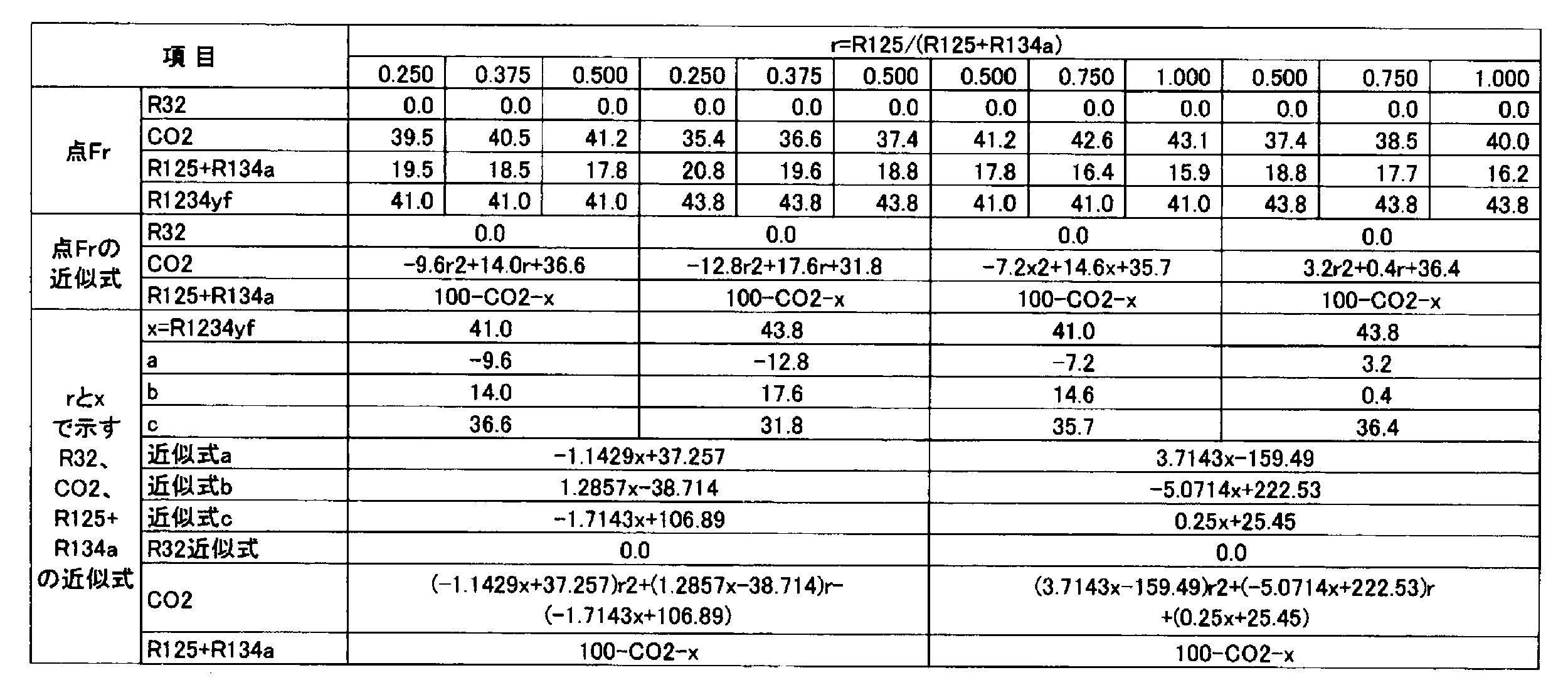
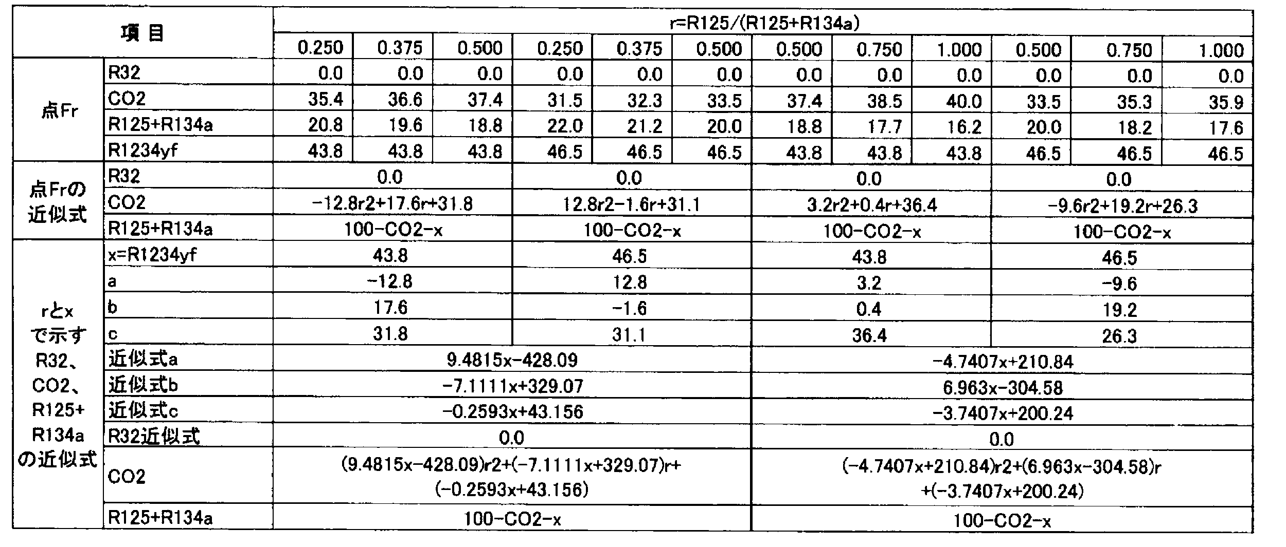
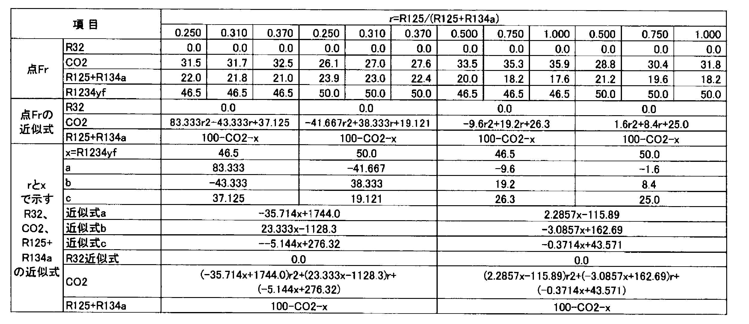
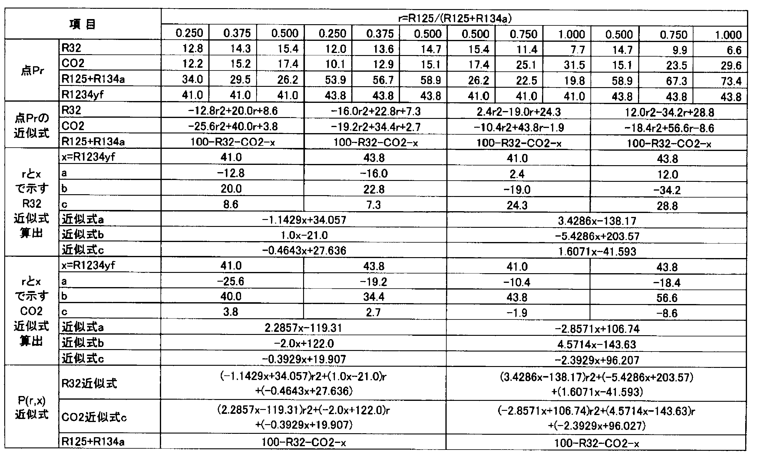

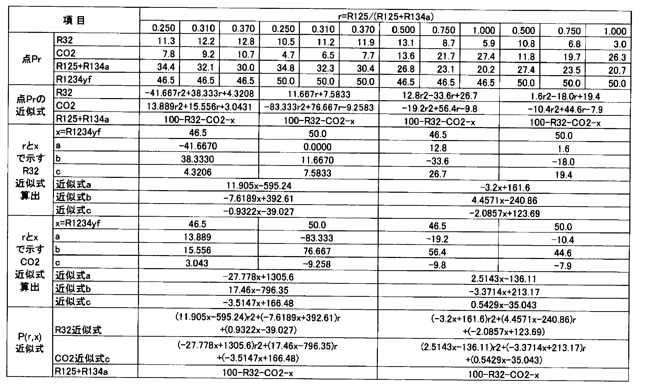
以下、本開示において用いられる冷媒である冷媒3A、冷媒3Bについて、詳細に説明する。
本開示の組成物に含まれる冷媒は、一つの態様において、HFO-1132(Z)及びHFO-1234yfを含有する。この冷媒を「冷媒3A」ということがある。
本開示の組成物に含まれる冷媒は、一つの態様において、HFO-1132(Z)及びHFO-1234yfを含有し、HFO-1132(Z)及びHFO-1234yfの全質量に対して、HFO-1132(Z)の含有割合が41.0~49.2質量%であり、HFO-1234yfの含有割合が59.0~50.8質量%である。この冷媒を「冷媒3B」ということがある。
(用途)
本開示の冷媒を含有する組成物は、作動流体として、1)冷凍サイクルを運転する工程を含む冷凍方法、2)冷凍サイクルを運転する冷凍装置の運転方法等における既存の冷媒の用途に幅広く利用することができる。
本開示の冷媒組成物は、本開示の冷媒を少なくとも含み、本開示の冷媒と同じ用途のために使用することができる。
本開示の冷媒組成物は微量の水を含んでもよい。
トレーサーは、本開示の冷媒組成物が希釈、汚染、その他何らかの変更があった場合、その変更を追跡できるように検出可能な濃度で本開示の冷媒組成物に添加される。
HCC-40(クロロメタン、CH3Cl)
HFC-41(フルオロメタン、CH3F)
HFC-161(フルオロエタン、CH3CH2F)
HFC-245fa(1,1,1,3,3-ペンタフルオロプロパン、CF3CH2CHF2)
HFC-236fa(1,1,1,3,3,3-ヘキサフルオロプロパン、CF3CH2CF3)
HFC-236ea(1,1,1,2,3,3-ヘキサフルオロプロパン、CF3CHFCHF2)
HCFC-22(クロロジフルオロメタン、CHClF2)
HCFC-31(クロロフルオロメタン、CH2ClF)
CFC-1113(クロロトリフルオロエチレン、CF2=CClF)
HFE-125(トリフルオロメチル-ジフルオロメチルエーテル、CF3OCHF2)
HFE-134a(トリフルオロメチル-フルオロメチルエーテル、CF3OCH2F)
HFE-143a(トリフルオロメチル-メチルエーテル、CF3OCH3)
HFE-227ea(トリフルオロメチル-テトラフルオロエチルエーテル、CF3OCHFCF3)
HFE-236fa(トリフルオロメチル-トリフルオロエチルエーテル、CF3OCH2CF3)
上記トレーサー化合物は、10質量百万分率(ppm)~1000ppmの合計濃度で冷媒組成物中に存在し得る。上記トレーサー化合物は30ppm~500ppmの合計濃度で冷媒組成物中に存在することが好ましく、50ppm~300ppmの合計濃度で冷媒組成物中に存在することがより好ましく、75ppm~250ppmの合計濃度で冷媒組成物中に存在することが更に好ましく、100ppm~200ppmの合計濃度で冷媒組成物中に存在することが特に好ましい。
本開示の冷媒組成物は、紫外線蛍光染料を1種単独で含有してもよいし、2種以上を含有してもよい。
本開示の冷媒組成物は、安定剤を1種単独で含有してもよいし、2種以上を含有してもよい。
本開示の冷媒組成物は、重合禁止剤を1種単独で含有してもよいし、2種以上を含有してもよい。
キノンメチルエーテル、ジメチル-t-ブチルフェノール、2,6-ジ-tert-ブチル-p-クレゾール、ベンゾトリアゾール等が挙げられる。
量%であり、0.05~3質量%が好ましく、0.1~2質量%がより好ましく、0.25~1.5質量%が更に好ましく、0.5~1質量%が特に好ましい。
本開示の冷媒組成物は、以下の成分も含み得るものとして挙げられる。
式(B)で表わされる有機化合物の含有量は限定的ではないが、これらの合計量として、冷
媒組成物の全量に対して0.5質量%以下が好ましく、0.3質量%以下がより好ましく、0.1質量%以下が特に好ましい。
本開示の冷凍機油含有作動流体は、本開示の冷媒又は冷媒組成物と、冷凍機油とを少なくとも含み、冷凍装置における作動流体として用いられる。具体的には、本開示の冷凍機油含有作動流体は、冷凍装置の圧縮機において使用される冷凍機油と、冷媒又は冷媒組成物とが互いに混じり合うことにより得られる。
本開示の組成物は、冷凍機油を1種単独で含有してもよいし、2種以上を含有してもよい。
好ましい。
本開示の冷凍機油含有作動流体は、相溶化剤を一種単独で含有してもよいし、二種以上を含有してもよい。
実施例1-1~1-3、比較例1-1~1-6及び参考例1-1(R134a)に示される混合冷媒のGWPは、IPCC第4次報告書の値に基づいて評価した。
<空調条件>
蒸発温度 10℃
凝縮温度 40℃
過熱温度 20K
過冷却温度 0K
圧縮機効率 70%
COP=(冷凍能力又は暖房能力)/消費電力量
圧縮比=凝縮圧力(Mpa)/蒸発圧力(Mpa)
超となる混合冷媒は「クラス2(弱燃)」であるとした。R134aは火炎伝播がなかったため、「クラス1(不燃)」であるとした。表401中、「ASHRAE燃焼性区分」とは、この判定基準に基づく結果を示している。
試験容器:280mmφ球形(内容積:12リットル)
試験温度:60℃±3℃
圧力:101.3kPa±0.7kPa
水分:乾燥空気1gにつき0.0088g±0.0005g(23℃における相対湿度50%の水分量)
冷媒組成物/空気混合比:1vol.%刻み±0.2vol.%
冷媒組成物混合:±0.1質量%
点火方法:交流放電、電圧15kV、電流30mA、ネオン変圧器
電極間隔:6.4mm(1/4inch)
スパーク:0.4秒±0.05秒
判定基準:
・着火点を中心に90度より大きく火炎が広がった場合=火炎伝播あり(可燃)
・着火点を中心に90度以下の火炎の広がりだった場合=火炎伝播なし(不燃)

実施例1-4~1-6、比較例1-7~1-12及び参考例1-2(R134a)に示される混合冷媒のGWPは、IPCC第4次報告書の値に基づいて評価した。
<空調条件>
蒸発温度 5℃
凝縮温度 45℃
過熱温度 5K
過冷却温度 5K
圧縮機効率 70%
上記用語の意味は、試験例1-1と同様である。
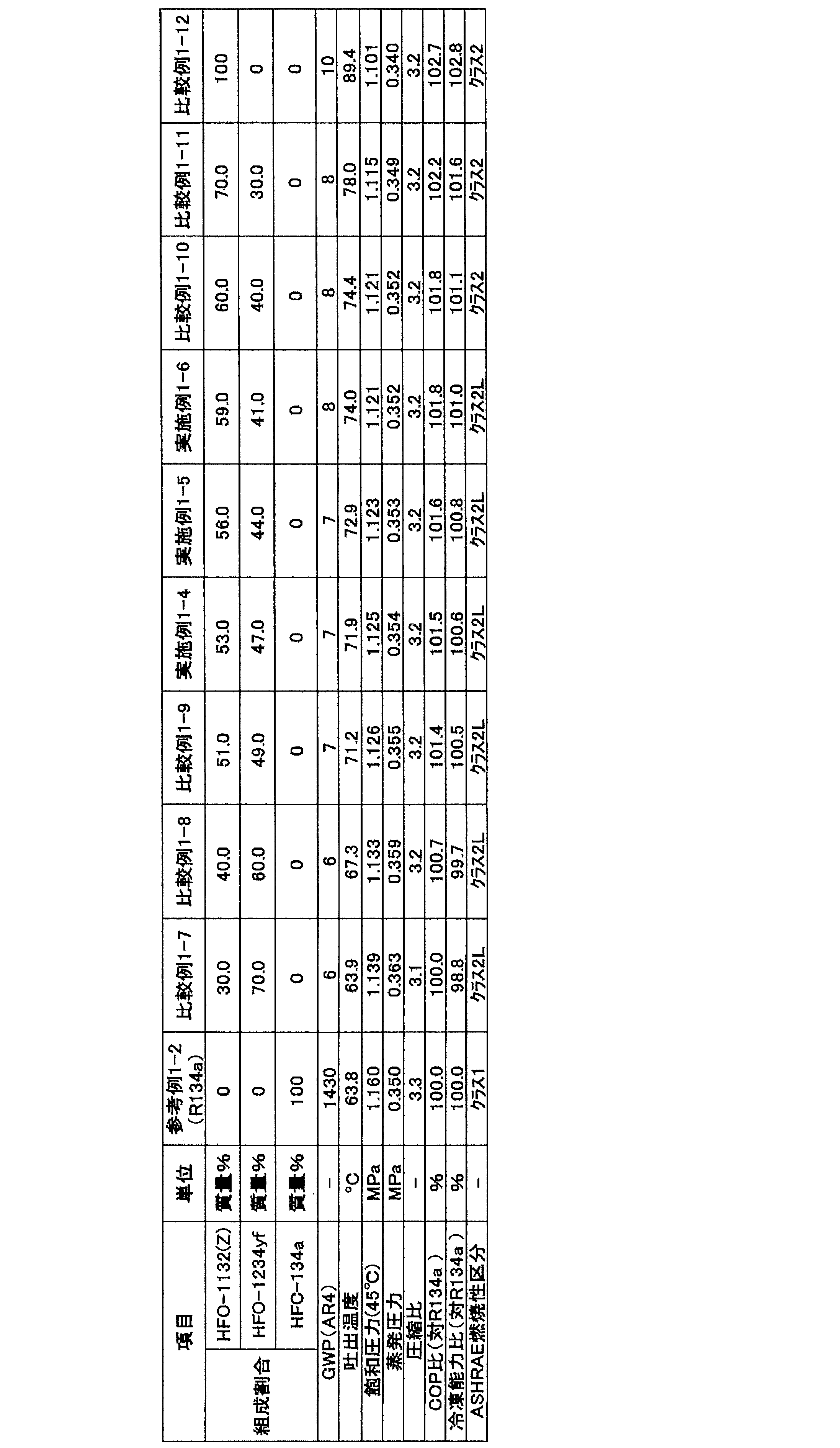
実施例1-7~1-9、比較例1-13~1-18及び参考例1-3(R134a)に示される混合冷媒のGWPは、IPCC第4次報告書の値に基づいて評価した。
<空調条件>
蒸発温度 -10℃
凝縮温度 40℃
過熱温度 20K
過冷却温度 0K
圧縮機効率 70%
上記用語の意味は、試験例1-1と同様である。
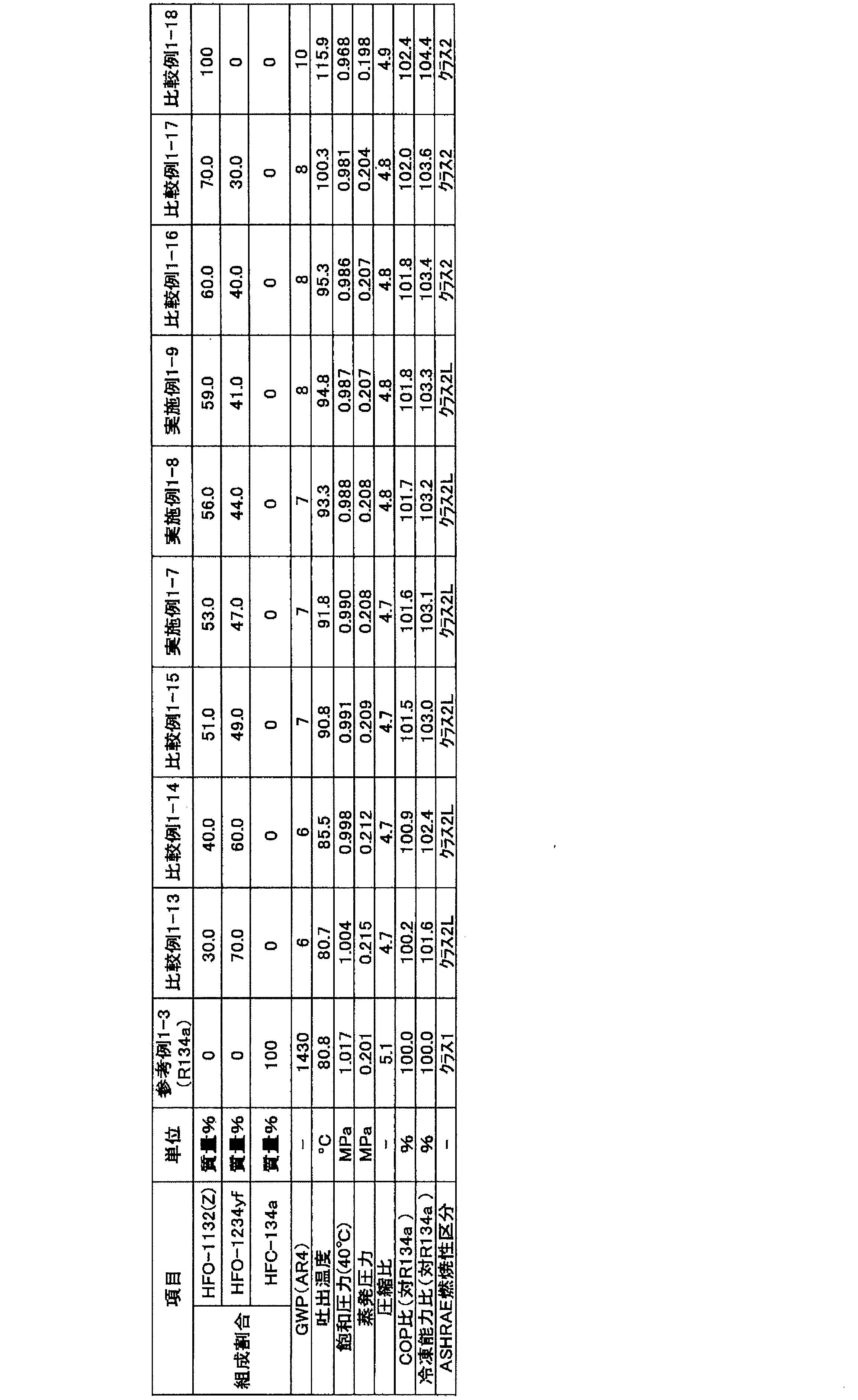
実施例1-10~1-12、比較例1-19~1-24及び参考例1-4(R134a)に示される混合冷媒のGWPは、IPCC第4次報告書の値に基づいて評価した。
蒸発温度 -35℃
凝縮温度 40℃
過熱温度 20K
過冷却温度 0K
圧縮機効率 70%

実施例1-13~1-15、比較例1-25~1-30及び参考例1-5(R134a)に示される混合冷媒のGWPは、IPCC第4次報告書の値に基づいて評価した。
<空調条件>
蒸発温度 -50℃
凝縮温度 40℃
過熱温度 20K
過冷却温度 0K
圧縮機効率 70%
上記用語の意味は、試験例1-1と同様である。

実施例1-16~1-18、比較例1-31~1-36及び参考例1-6(R134a)に示される混合冷媒のGWPは、IPCC第4次報告書の値に基づいて評価した。
蒸発温度 -65℃
凝縮温度 40℃
過熱温度 20K
過冷却温度 0K
圧縮機効率 70%
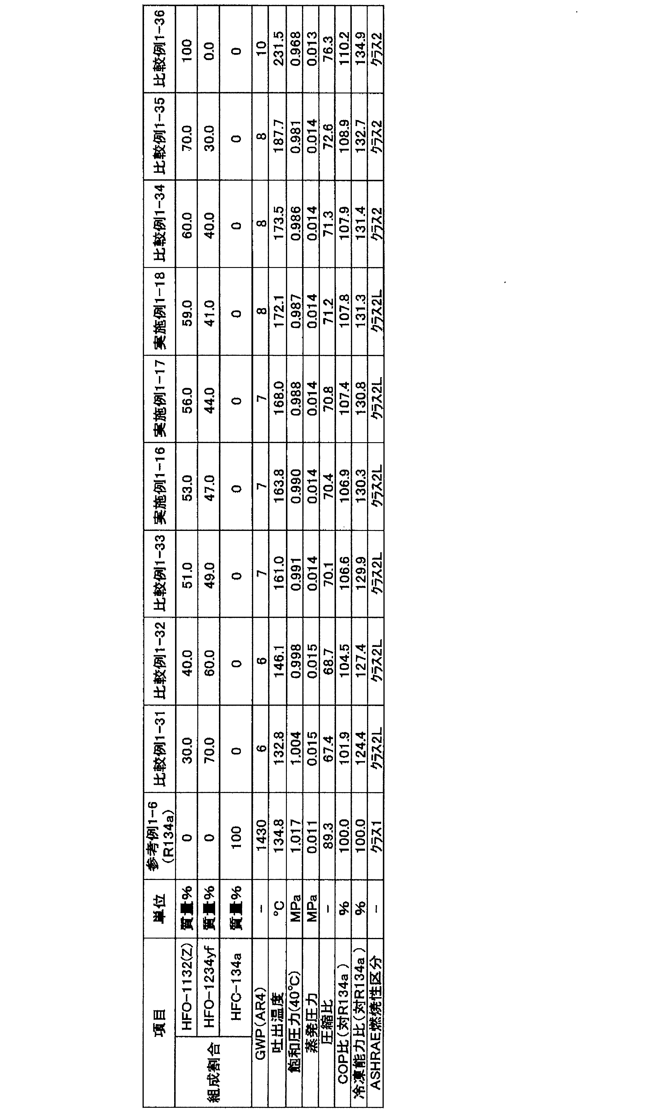
実施例2-1~2-4、比較例2-1~2-6及び参考例2-1(R134a)に示される混合冷媒のGWPは、IPCC第4次報告書の値に基づいて評価した。
<空調条件>
蒸発温度 10℃
凝縮温度 40℃
過熱温度 20K
過冷却温度 0K
圧縮機効率 70%
「蒸発温度10℃」とは、冷凍装置が備える蒸発器における混合冷媒の蒸発温度が10℃であることを意味する。また、「凝縮温度40℃」とは、冷凍装置が備える凝縮器における混合冷媒の凝縮温度が40℃であることを意味する。
COP=(冷凍能力又は暖房能力)/消費電力量
圧縮比=凝縮圧力(Mpa)/蒸発圧力(Mpa)
試験容器:280mmφ球形(内容積:12リットル)
試験温度:60℃±3℃
圧力:101.3kPa±0.7kPa
水分:乾燥空気1gにつき0.0088g±0.0005g(23℃における相対湿度50%の水分量)
冷媒組成物/空気混合比:1vol.%刻み±0.2vol.%
冷媒組成物混合:±0.1質量%
点火方法:交流放電、電圧15kV、電流30mA、ネオン変圧器
電極間隔:6.4mm(1/4inch)
スパーク:0.4秒±0.05秒
判定基準:
・着火点を中心に90度より大きく火炎が広がった場合=火炎伝播あり(可燃)
・着火点を中心に90度以下の火炎の広がりだった場合=火炎伝播なし(不燃)
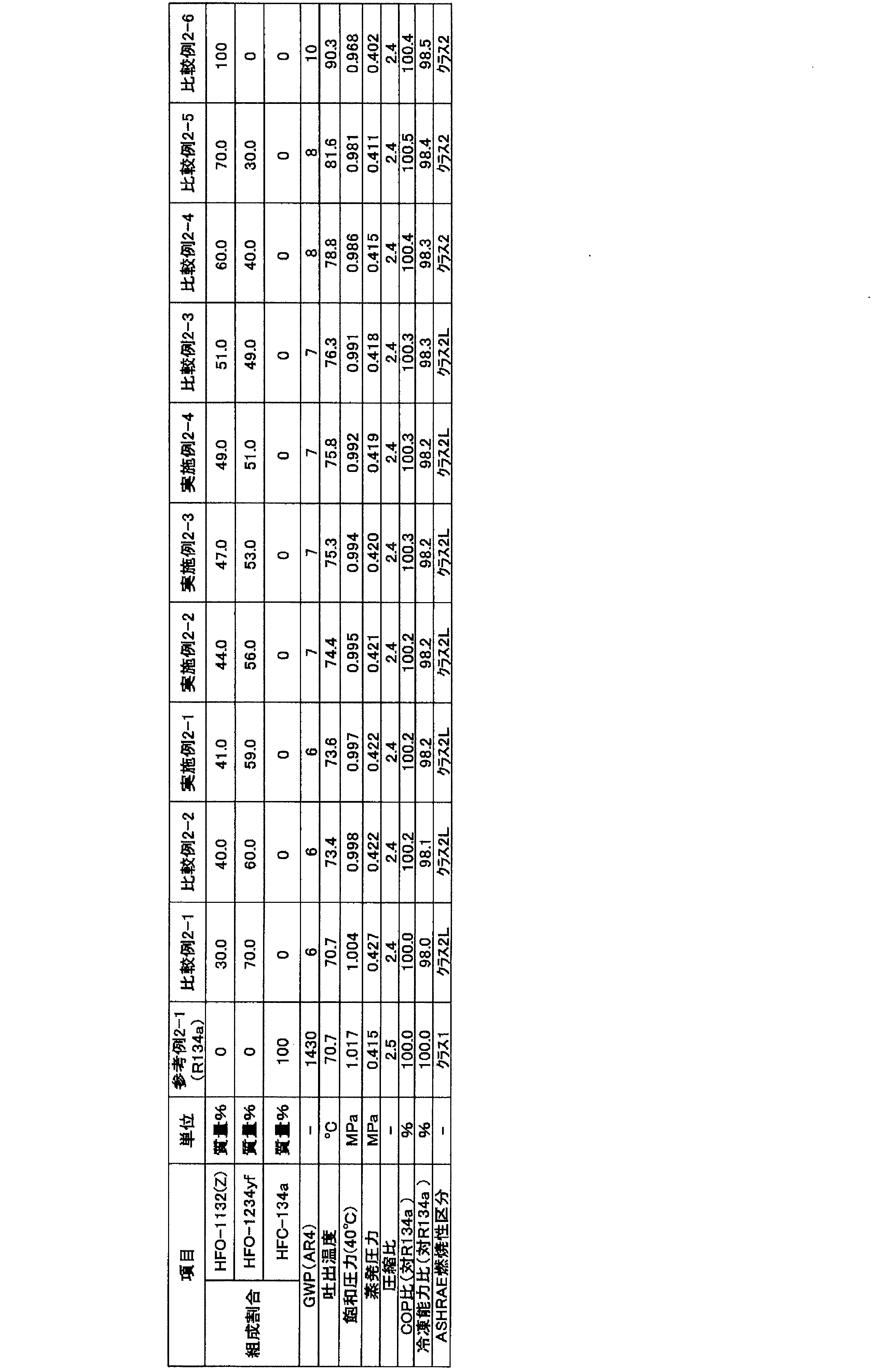
実施例2-5~2-8、比較例2-7~2-12及び参考例2-2(R134a)に示され
る混合冷媒のGWPは、IPCC第4次報告書の値に基づいて評価した。
圧力及び蒸発圧力は、NIST、Refprop 9.0を使用し、下記条件で混合冷媒の冷凍サイクル
理論計算を実施することにより求めた。
<空調条件>
蒸発温度 5℃
凝縮温度 45℃
過熱温度 5K
過冷却温度 5K
圧縮機効率 70%
上記用語の意味は、試験例2-1と同様である。

実施例2-9~2-12、比較例2-13~2-18及び参考例2-3(R134a)に示される混合冷媒のGWPは、IPCC第4次報告書の値に基づいて評価した。
蒸発温度 -10℃
凝縮温度 40℃
過熱温度 20K
過冷却温度 0K
圧縮機効率 70%

実施例2-13~2-16、比較例2-19~2-24及び参考例2-4(R134a)に示される混合冷媒のGWPは、IPCC第4次報告書の値に基づいて評価した。
<空調条件>
蒸発温度 -35℃
凝縮温度 40℃
過熱温度 20K
過冷却温度 0K
圧縮機効率 70%
上記用語の意味は、試験例2-1と同様である。
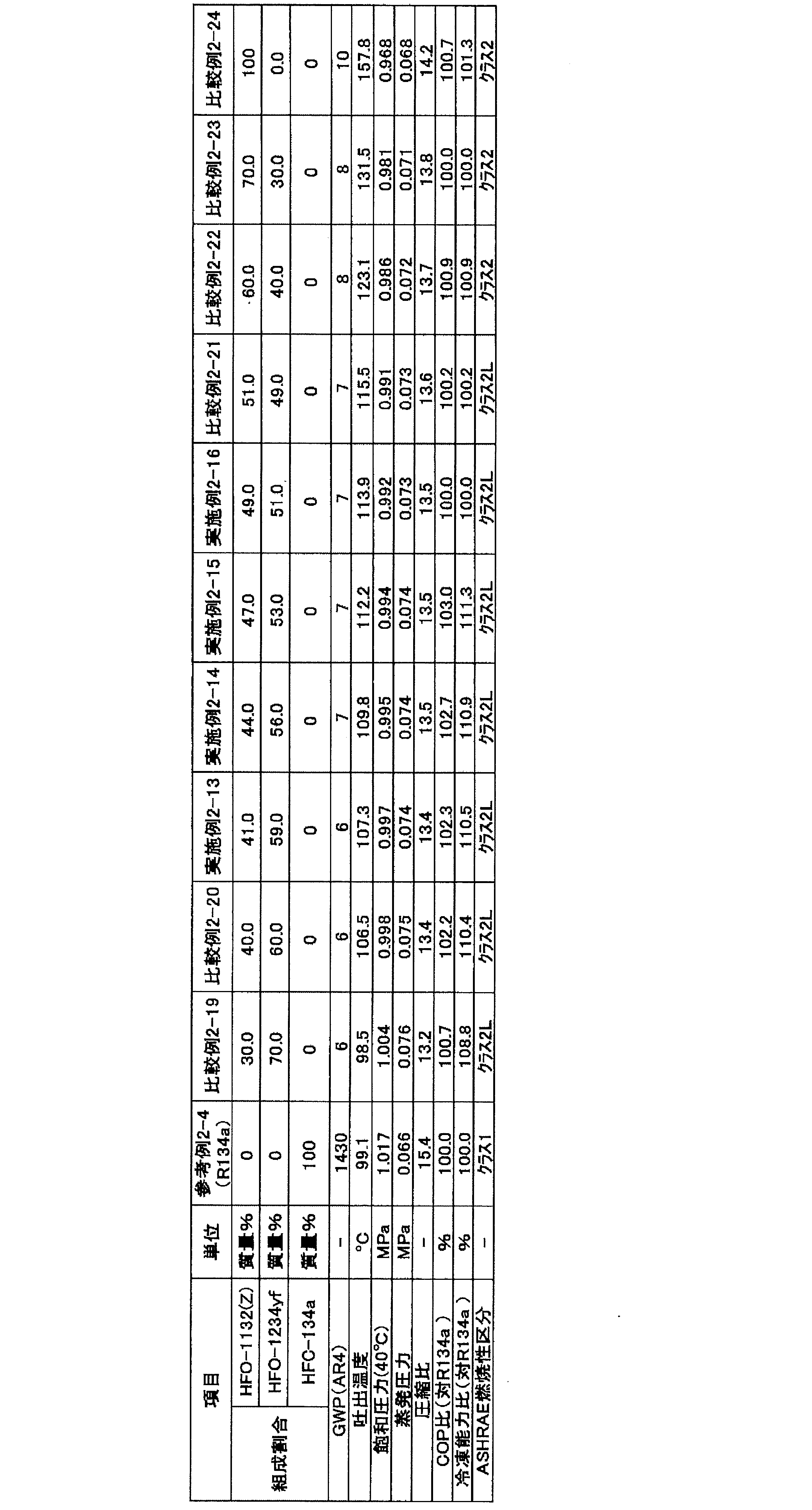
実施例2-17~2-20、比較例2-25~2-30及び参考例2-5(R134a)に示される混合冷媒のGWPは、IPCC第4次報告書の値に基づいて評価した。
蒸発温度 -50℃
凝縮温度 40℃
過熱温度 20K
過冷却温度 0K
圧縮機効率 70%
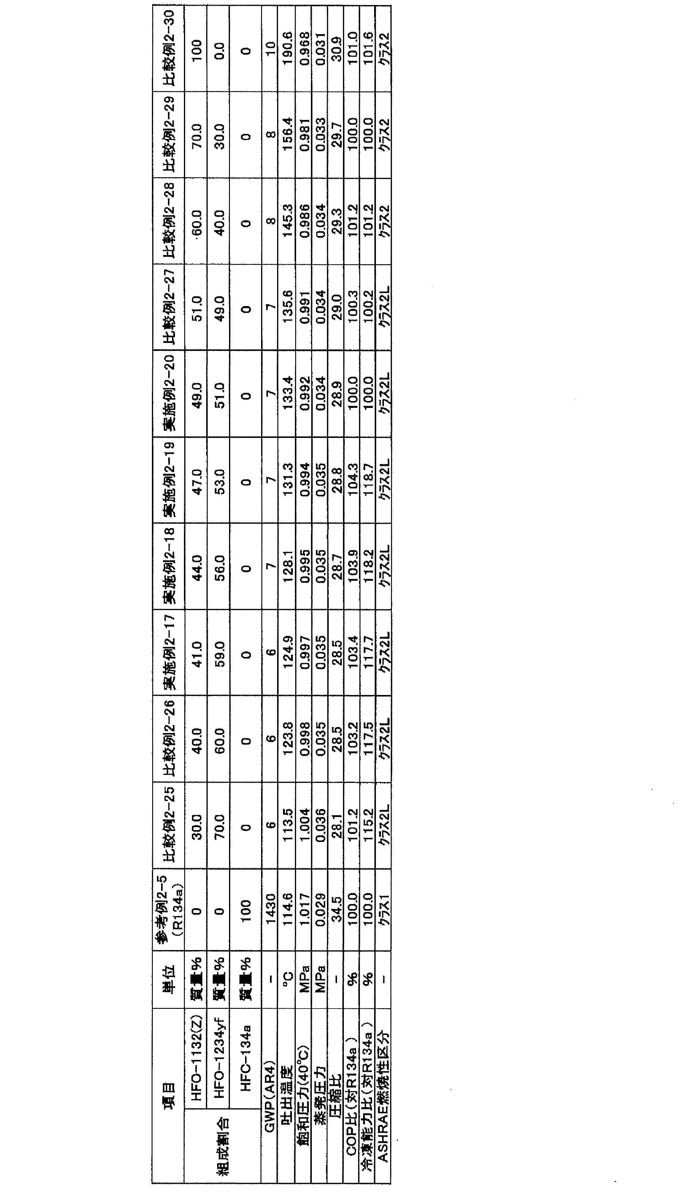
実施例2-21~2-24、比較例2-31~2-36及び参考例2-6(R134a)に示される混合冷媒のGWPは、IPCC第4次報告書の値に基づいて評価した。
蒸発温度 -65℃
凝縮温度 40℃
過熱温度 20K
過冷却温度 0K
圧縮機効率 70%

第2グループの技術としての冷凍機油は、冷媒組成物と共存させて冷凍サイクルを行わせることで、冷凍サイクル装置内の潤滑性を高めることが可能であり、効率的なサイクル性能を発揮させることも可能となる。
含酸素系合成油であるエステル系冷凍機油やエーテル系冷凍機油は、主として、炭素原子と酸素原子を有して構成されている。エステル系冷凍機油やエーテル系冷凍機油においては、この炭素原子と酸素原子の比率(炭素/酸素モル比)が小さすぎると吸湿性が高くなり、当該比率が大きすぎると冷媒との相溶性が低下してしまうことから、当該比率はモル比で2以上7.5以下であることが好ましい。
エステル系冷凍機油としては、化学的安定性の観点から、二塩基酸と1価アルコールとの二塩基酸エステル油、ポリオールと脂肪酸とのポリオールエステル油、またはポリオールと多価塩基酸と1価アルコール(又は脂肪酸)とのコンプレックスエステル油、ポリオール炭酸エステル油等が基油成分として挙げられる。
二塩基酸エステル油としては、シュウ酸、マロン酸、コハク酸、グルタル酸、アジピン酸、ピメリン酸、スベリン酸、アゼライン酸、セバシン酸、フタル酸、イソフタル酸、テレフタル酸等の二塩基酸、特に、炭素数5~10の二塩基酸(グルタル酸、アジピン酸、ピメリン酸、スベリン酸、アゼライン酸、セバシン酸等)と、直鎖または分枝アルキル基を有する炭素数1~15の一価アルコール(メタノール、エタノール、プロパノール、ブタノール、ペンタノール、ヘキサノール、ヘプタノール、オクタノール、ノナノール、デカノール、ウンデカノール、ドデカノール、トリデカノール、テトラデカノール、ペンタデカノール等)とのエステルが好ましい。この二塩基酸エステル油としては、具体的には、グルタル酸ジトリデシル、アジピン酸ジ(2-エチルヘキシル)、アジピン酸ジイソデシル、アジピン酸ジトリデシル、セバシン酸ジ(3-エチルヘキシル)等が挙げられる。
ポリオールエステル油とは、多価アルコールと脂肪酸(カルボン酸)とから合成されるエステルであり、炭素/酸素モル比が2以上7.5以下、好ましくは3.2以上5.8以下のものである。
(i)ブタン酸、2-メチルプロパン酸、ペンタン酸、2-メチルブタン酸、3-メチルブタン酸、2,2-ジメチルプロパン酸、2-メチルペンタン酸、3-メチルペンタン酸、4-メチルペンタン酸、2,2-ジメチルブタン酸、2,3-ジメチルブタン酸、3,3-ジメチルブタン酸およびヘキサン酸から選ばれる1~13種と、2-メチルヘキサン酸、3-メチルヘキサン酸、4-メチルヘキサン酸、5-メチルヘキサン酸、2,2-ジメチルペンタン酸、2,3-ジメチルペンタン酸、2,4-ジメチルペンタン酸、3,3-ジメチルペンタン酸、3,4-ジメチルペンタン酸、4,4-ジメチルペンタン酸、2-エチルペンタン酸、3-エチルペンタン酸および2-エチル-3-メチルブタン酸から選ばれる1~13種との組合せ;
(ii)ブタン酸、2-メチルプロパン酸、ペンタン酸、2-メチルブタン酸、3-メチルブタン酸、2,2-ジメチルプロパン酸、2-メチルペンタン酸、3-メチルペンタン酸、4-メチルペンタン酸、2,2-ジメチルブタン酸、2,3-ジメチルブタン酸、3,3-ジメチルブタン酸およびヘキサン酸から選ばれる1~13種と、2-メチルヘプタン酸、3-メチルヘプタン酸、4-メチルヘプタン酸、5-メチルヘプタン酸、6-メチルヘプタン酸、2,2-ジメチルヘキサン酸、3,3-ジメチルヘキサン酸、4,4-ジメチルヘキサン酸、5,5-ジメチルヘキサン酸、2,3-ジメチルヘキサン酸、2,4-ジメチルヘキサン酸、2,5-ジメチルヘキサン酸、3,4-ジメチルヘキサン酸、3,5-ジメチルヘキサン酸、4,5-ジメチルヘキサン酸、2,2,3-トリメチルペンタン酸、2,3,3-トリメチルペンタン酸、2,4,4-トリメチルペンタン酸、3,4,4-トリメチルペンタン酸、2-エチルヘキサン酸、3-エチルヘキサン酸、2-プロピルペンタン酸、2-メチル-2-エチルペンタン酸、2-メチル-3-エチルペンタン酸および3-メチル-3-エチルペンタン酸から選ばれる1~25種との組合せ;
(iii)ブタン酸、2-メチルプロパン酸、ペンタン酸、2-メチルブタン酸、3-メチルブタン酸、2,2-ジメチルプロパン酸、2-メチルペンタン酸、3-メチルペンタン酸、4-メチルペンタン酸、2,2-ジメチルブタン酸、2,3-ジメチルブタン酸、3,3-ジメチルブタン酸およびヘキサン酸から選ばれる1~13種と、2-メチルオクタン酸、3-メチルオクタン酸、4-メチルオクタン酸、5-メチルオクタン酸、6-メチルオクタン酸、7-メチルオクタン酸、8-メチルオクタン酸、2,2-ジメチルヘプタン酸、3,3-ジメチルヘプタン酸、4,4-ジメチルヘプタン酸、5,5-ジメチルヘプタン酸、6,6-ジメチルヘプタン酸、2,3-ジメチルヘプタン酸、2,4-ジメチルヘプタン酸、2,5-ジメチルヘプタン酸、2,6-ジメチルヘプタン酸、3,4-ジメチルヘプタン酸、3,5-ジメチルヘプタン酸、3,6-ジメチルヘプタン酸、4,5-ジメチルヘプタン酸、4,6-ジメチルヘプタン酸、2-エチルヘプタン酸、3-エチルヘプタン酸、4-エチルヘプタン酸、5-エチルヘプタン酸、2-プロピルヘキサン酸、3-プロピルヘキサン酸、2-ブチルペンタン酸、2,2,3-トリメチルヘキサン酸、2,2,3-トリメチルヘキサン酸、2,2,4-トリメチルヘキサン酸、2,2,5-トリメチルヘキサン酸、2,3,4-トリメチルヘキサン酸、2,3,5-トリメチルヘキサン酸、3,3,4-トリメチルヘキサン酸、3,3,5-トリメチルヘキサン酸、3,5,5-トリメチルヘキサン酸、4,4,5-トリメチルヘキサン酸、4,5,5-トリメチルヘキサン酸、2,2,3,3-テトラメチルペンタン酸、2,2,3,4-テトラメチルペンタン酸、2,2,4,4-テトラメチルペンタン酸、2,3,4,4-テトラメチルペンタン酸、3,3,4,4-テトラメチルペンタン酸、2,2-ジエチルペンタン酸、2,3-ジエチルペンタン酸、3,3-ジエチルペンタン酸、2-エチル-2,3,3-トリメチル酪酸、3-エチル-2,2,3-トリメチル酪酸および2,2-ジイソプロピルプロピオン酸から選ばれる1~50種との組合せ。
(i)2-メチルプロパン酸と、2-メチルヘキサン酸、3-メチルヘキサン酸、4-メチルヘキサン酸、5-メチルヘキサン酸、2,2-ジメチルペンタン酸、2,3-ジメチルペンタン酸、2,4-ジメチルペンタン酸、3,3-ジメチルペンタン酸、3,4-ジメチルペンタン酸、4,4-ジメチルペンタン酸、2-エチルペンタン酸、3-エチルペンタン酸および2-エチル-3-メチルブタン酸から選ばれる1~13種との組合せ;
(ii)2-メチルプロパン酸と、2-メチルヘプタン酸、3-メチルヘプタン酸、4-メチルヘプタン酸、5-メチルヘプタン酸、6-メチルヘプタン酸、2,2-ジメチルヘキサン酸、3,3-ジメチルヘキサン酸、4,4-ジメチルヘキサン酸、5,5-ジメチルヘキサン酸、2,3-ジメチルヘキサン酸、2,4-ジメチルヘキサン酸、2,5-ジメチルヘキサン酸、3,4-ジメチルヘキサン酸、3,5-ジメチルヘキサン酸、4,5-ジメチルヘキサン酸、2,2,3-トリメチルペンタン酸、2,3,3-トリメチルペンタン酸、2,4,4-トリメチルペンタン酸、3,4,4-トリメチルペンタン酸、2-エチルヘキサン酸、3-エチルヘキサン酸、2-プロピルペンタン酸、2-メチル-2-エチルペンタン酸、2-メチル-3-エチルペンタン酸および3-メチル-3-エチルペンタン酸から選ばれる1~25種との組合せ;
(iii)2-メチルプロパン酸と、2-メチルオクタン酸、3-メチルオクタン酸、4-メチルオクタン酸、5-メチルオクタン酸、6-メチルオクタン酸、7-メチルオクタン酸、8-メチルオクタン酸、2,2-ジメチルヘプタン酸、3,3-ジメチルヘプタン酸、4,4-ジメチルヘプタン酸、5,5-ジメチルヘプタン酸、6,6-ジメチルヘプタン酸、2,3-ジメチルヘプタン酸、2,4-ジメチルヘプタン酸、2,5-ジメチルヘプタン酸、2,6-ジメチルヘプタン酸、3,4-ジメチルヘプタン酸、3,5-ジメチルヘプタン酸、3,6-ジメチルヘプタン酸、4,5-ジメチルヘプタン酸、4,6-ジメチルヘプタン酸、2-エチルヘプタン酸、3-エチルヘプタン酸、4-エチルヘプタン酸、5-エチルヘプタン酸、2-プロピルヘキサン酸、3-プロピルヘキサン酸、2-ブチルペンタン酸、2,2,3-トリメチルヘキサン酸、2,2,3-トリメチルヘキサン酸、2,2,4-トリメチルヘキサン酸、2,2,5-トリメチルヘキサン酸、2,3,4-トリメチルヘキサン酸、2,3,5-トリメチルヘキサン酸、3,3,4-トリメチルヘキサン酸、3,3,5-トリメチルヘキサン酸、3,5,5-トリメチルヘキサン酸、4,4,5-トリメチルヘキサン酸、4,5,5-トリメチルヘキサン酸、2,2,3,3-テトラメチルペンタン酸、2,2,3,4-テトラメチルペンタン酸、2,2,4,4-テトラメチルペンタン酸、2,3,4,4-テトラメチルペンタン酸、3,3,4,4-テトラメチルペンタン酸、2,2-ジエチルペンタン酸、2,3-ジエチルペンタン酸、3,3-ジエチルペンタン酸、2-エチル-2,3,3-トリメチル酪酸、3-エチル-2,2,3-トリメチル酪酸および2,2-ジイソプロピルプロピオン酸から選ばれる1~50種との組合せ。
コンプレックスエステル油とは、脂肪酸および二塩基酸と、一価アルコールおよびポリオールとのエステルである。脂肪酸、二塩基酸、一価アルコール、ポリオールとしては、上述と同様のものを用いることができる。
ポリオール炭酸エステル油とは、炭酸とポリオールとのエステルである。
エーテル系冷凍機油としては、ポリビニルエーテル油、ポリオキシアルキレン油等が挙げられる。
ポリビニルエーテル油としては、ビニルエーテルモノマーの重合体、ビニルエーテルモノマーとオレフィン性二重結合を有する炭化水素モノマーとの共重合体、オレフィン性二重結合とポリオキシアルキレン鎖を有するモノマーとビニルエーテルモノマーとの共重合体等が挙げられる。
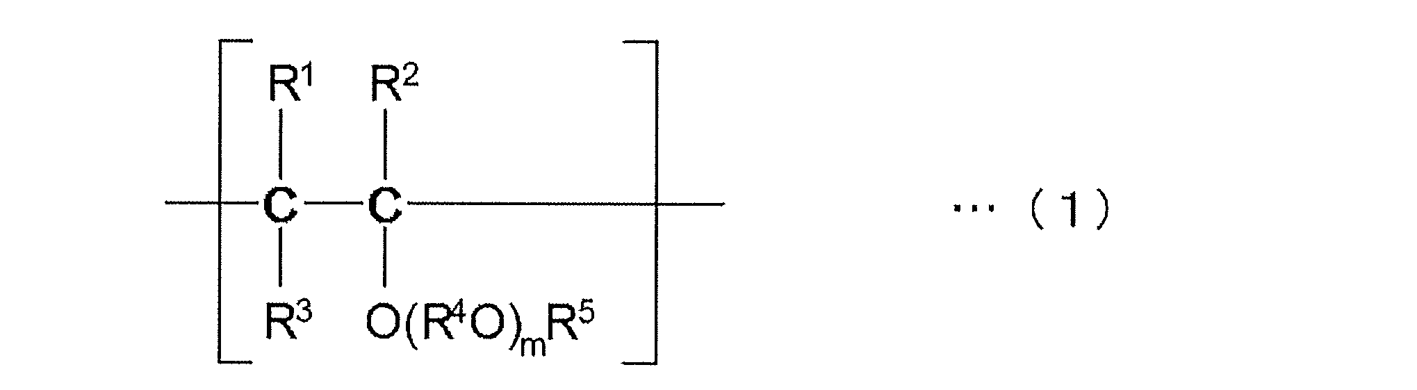
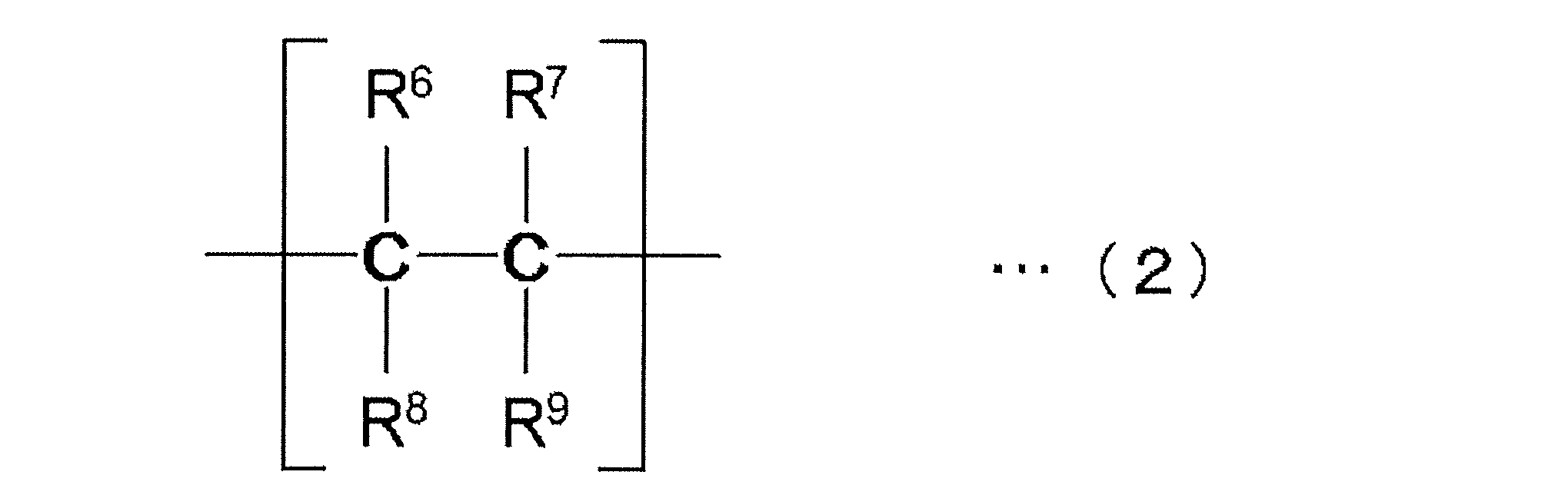

上記ポリビニルエーテル系化合物に対応する各種のものがあるが、例えば、ビニルメチルエーテル;ビニルエチルエーテル;ビニル-n-プロピルエーテル;ビニル-イソプロピルエーテル;ビニル-n-ブチルエーテル;ビニル-イソブチルエーテル;ビニル-sec-ブチルエーテル;ビニル-tert-ブチルエーテル;ビニル-n-ペンチルエーテル;ビニル-n-ヘキシルエーテル;ビニル-2-メトキシエチルエーテル;ビニル-2-エトキシエチルエーテル;ビニル-2-メトキシ-1-メチルエチルエーテル;ビニル-2-メトキシ-プロピルエーテル;ビニル-3,6-ジオキサヘプチルエーテル;ビニル-3,6,9-トリオキサデシルエーテル;ビニル-1,4-ジメチル-3,6-ジオキサヘプチルエーテル;ビニル-1,4,7-トリメチル-3,6,9-トリオキサデシルエーテル;ビニル-2,6-ジオキサ-4-ヘプチルエーテル;ビニル-2,6,9-トリオキサ-4-デシルエーテル;1-メトキシプロペン;1-エトキシプロペン;1-n-プロポキシプロペン;1-イソプロポキシプロペン;1-n-ブトキシプロペン;1-イソブトキシプロペン;1-sec-ブトキシプロペン;1-tert-ブトキシプロペン;2-メトキシプロペン;2-エトキシプロペン;2-n-プロポキシプロペン;2-イソプロポキシプロペン;2-n-ブトキシプロペン;2-イソブトキシプロペン;2-sec-ブトキシプロペン;2-tert-ブトキシプロペン;1-メトキシ-1-ブテン;1-エトキシ-1-ブテン;1-n-プロポキシ-1-ブテン;1-イソプロポキシ-1-ブテン;1-n-ブトキシ-1-ブテン;1-イソブトキシ-1-ブテン;1-sec-ブトキシ-1-ブテン;1-tert-ブトキシ-1-ブテン;2-メトキシ-1-ブテン;2-エトキシ-1-ブテン;2-n-プロポキシ-1-ブテン;2-イソプロポキシ-1-ブテン;2-n-ブトキシ-1-ブテン;2-イソブトキシ-1-ブテン;2-sec-ブトキシ-1-ブテン;2-tert-ブトキシ-1-ブテン;2-メトキシ-2-ブテン;2-エトキシ-2-ブテン;2-n-プロポキシ-2-ブテン;2-イソプロポキシ-2-ブテン;2-n-ブトキシ-2-ブテン;2-イソブトキシ-2-ブテン;2-sec-ブトキシ-2-ブテン;2-tert-ブトキシ-2-ブテン等が挙げられる。これらのビニルエーテル系モノマーは公知の方法により製造することができる。


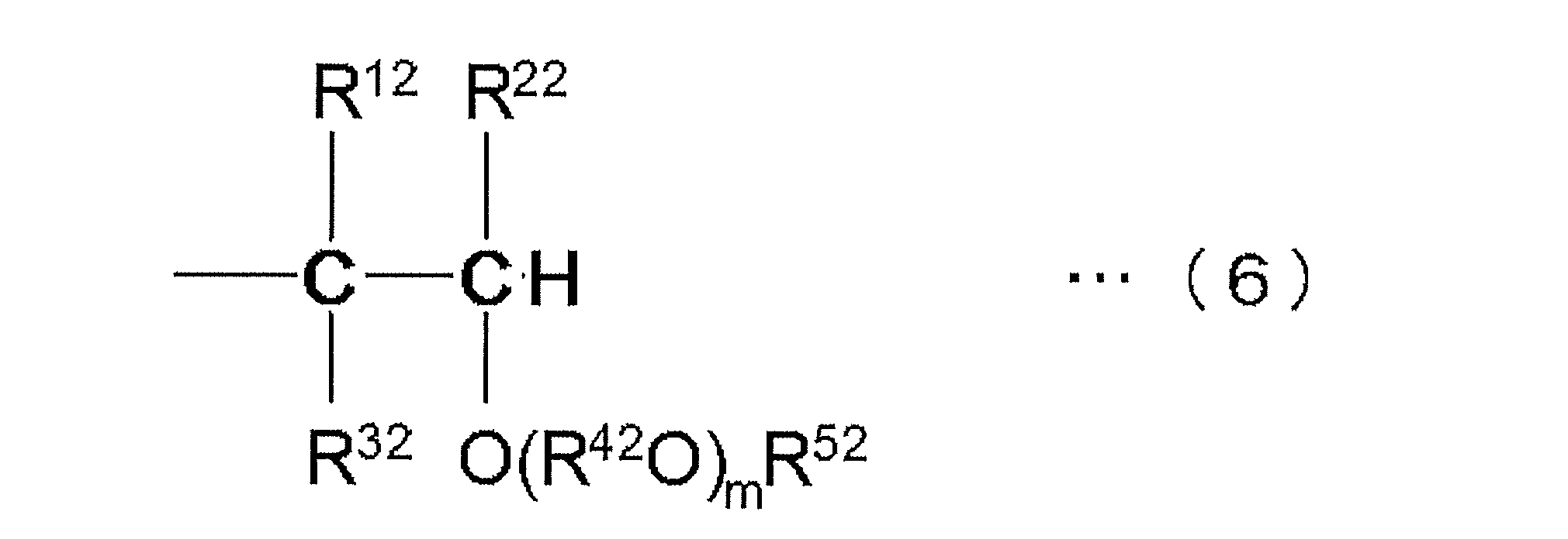
(式中、R12、R22およびR32は互いに同一でも異なっていてもよく、それぞれ水素原子または炭素数1~8の炭化水素基を示し、R42は炭素数1~10の二価の炭化水素基または炭素数2~20の二価のエーテル結合酸素含有炭化水素基を示し、R52は炭素数1~20の炭化水素基を示し、mはポリビニルエーテルについてのmの平均値が0~10となるような数を示し、mが2以上の場合には、複数のR42Oは同一でも異なっていてもよい。)

(式中、R62、R72、R82およびR92は互いに同一でも異なっていてもよく、それぞれ水素原子または炭素数1~20の炭化水素基を示す。)
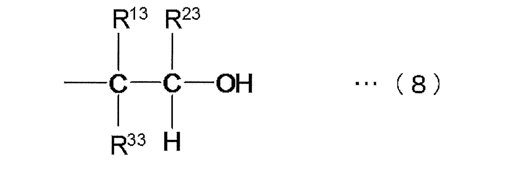
(式中、R13、R23およびR33は互いに同一でも異なっていてもよく、それぞれ水素原子または炭素数1~8の炭化水素基を示す。)
ポリオキシアルキレン油としては、炭素数2~4のアルキレンオキシド(エチレンオキシド、プロピレンオキシド等)を、水や水酸基含有化合物を開始剤として重合させる方法等により得られたポリオキシアルキレン化合物が挙げられる。また、ポリオキシアルキレン化合物の水酸基をエーテル化またはエステル化したものであってもよい。ポリオキシアルキレン油中のオキシアルキレン単位は、1分子中において同一であってもよく、2種以上のオキシアルキレン単位が含まれていてもよい。1分子中に少なくともオキシプロピレン単位が含まれることが好ましい。
R101-[(OR102)k-OR103]l …(9)
(式中、R101は水素原子、炭素数1~10のアルキル基、炭素数2~10のアシル基又は結合部2~6個を有する炭素数1~10の脂肪族炭化水素基、R102は炭素数2~4のアルキレン基、R103は水素原子、炭素数1~10のアルキル基又は炭素数2~10のアシル基、lは1~6の整数、kはk×lの平均値が6~80となる数を示す。)で表される化合物が挙げられる。
(式中、hは6~80の数を表す。)
CH3O-(C2H4O)i-(C3H6O)j-CH3 …(11)
(式中、iおよびjはそれぞれ1以上であり且つiとjとの合計が6~80となる数を表す。)
C4H9O-(C3H6O)h-H …(12)
(式中、hは6~80の数を示す。)
CH3O-(C3H6O)h-H …(13)
(式中、hは6~80の数を表す。)
CH3O-(C2H4O)i-(C3H6O)j-H …(14)
(式中、iおよびjはそれぞれ1以上であり且つiとjとの合計が6~80となる数を表す。)
C4H9O-(C2H4O)i-(C3H6O)j-H …(15)
(式中、iおよびjはそれぞれ1以上であり且つiとjとの合計が6~80となる数を表す。)
CH3COO-(C3H6O)h-COCH3 …(16)
(式中、hは6~80の数を表す。)
このポリオキシアルキレン油は、1種を単独で用いてもよく、2種以上を組み合わせて用いてもよい。
炭化水素系冷凍機油としては、例えば、アルキルベンゼンを用いることができる。
冷凍機油には、1種または2種以上の添加剤が含まれていてもよい。
リン酸エステル類としては、リン酸エステル、亜リン酸エステル、酸性リン酸エステル、及び酸性亜リン酸エステル等を用いることができ、リン酸エステル、亜リン酸エステル、酸性リン酸エステル、及び酸性亜リン酸エステルのアミン塩を含むものを用いることもできる。
以下、上記の冷媒1A、冷媒1B、冷媒1C、冷媒1D、冷媒1E、冷媒2A、冷媒2B、冷媒2C、冷媒2D、冷媒2E、冷媒3A、冷媒3Bのいずれか1つ及び冷凍機油を用いた自動車用空調装置について説明する。自動車用空調装置は、自動車用冷凍サイクル装置である。
図3は、本開示の第1実施形態に係る自動車用空調装置1の概略構成図である。図3において、自動車用空調装置1は、蒸気圧縮式の自動車用冷凍サイクル装置である。「自動車用の冷凍サイクル装置」とは、ガソリン車、ハイブリッド自動車、電気自動車、水素自動車などの自動車で用いられる冷凍サイクル装置の一種である。
図4は、暖房モードにおける冷媒の流通経路を示した自動車用空調装置1の概略構成図である。図4において、暖房モードにおける冷媒の流通部分を実線で示し、冷媒の流通が中止された部分を破線で示している。
圧縮機80では、圧縮機構がモータによって駆動される。モータとして、例えば、インバータから出力される交流電圧によって、その回転数が制御される交流モータが採用される。
外気用熱交換器82は、内部を流通する冷媒と室外ファン90から送風された車室外の空気とを熱交換させる。外気用熱交換器82は、暖房モード時には蒸発器として機能する。また、外気用熱交換器82は、冷房モード時には放熱器として機能する。室外ファン90は、制御装置60から出力される制御電圧によって回転数が制御される。
第1熱交換器85の冷媒出口と、外気用熱交換器82の冷媒入口との間には、暖房モード時に冷媒を減圧させる暖房用制御弁83が接続されている。暖房用制御弁83は、例えば、電動膨張弁であるが、それに限定されるものではない。
圧縮機80の吐出口と第1熱交換器85の冷媒入口とは吐出管によって接続されている。第1熱交換器85は、空調ユニット30において車室内へ送風される送風空気の空気通路を形成する空調ダクト31内に配置されている。
第2熱交換器86は、空調ダクト31内のうち、第1熱交換器85の送風空気流れの上流に配置されて、その内部を流通する冷媒と送風空気とを熱交換させて送風空気を冷却する冷却用熱交換器である。第2熱交換器86の冷媒出口とアキュムレータ80aの入口とは配管によって接続されている。アキュムレータ80aは、内部に流入した冷媒の気液を分離して、サイクル内の余剰冷媒を蓄える気液分離器である。さらに、アキュムレータ80aの気相冷媒出口と圧縮機80の吸入口とは吸入管によって接続される。
外気用熱交換器82の冷媒出口と第2熱交換器86の冷媒入口との間には、冷房モード時に冷媒を減圧させる冷房用制御弁87が接続されている。
外気用熱交換器82の冷媒出口と第2熱交換器86の冷媒出口との間には、逆止弁24、冷房用制御弁87および第2熱交換器86を迂回するバイパス22が設けられている。バイパス22には電磁弁23が設けられている。
電磁弁23は、開閉弁である。電磁弁23は、冷房モードにおける冷媒回路、暖房モードにおける冷媒回路を切り替える冷媒回路切替手段である。電磁弁23は、制御装置60から出力される制御信号によって、その作動が制御される。電磁弁23は、冷房モード時に閉じられ、暖房モード時に開放される。
外気用熱交換器82の冷媒出口と第2熱交換器86の冷媒入口とを繋ぐ冷媒通路には、逆止弁24が設けられている。逆止弁24は、外気用熱交換器82の冷媒出口から第2熱交換器86の冷媒入口への冷媒の流通を許容し、逆方向への冷媒の流通を禁止する。
空調ユニット30は、例えば、車室内最前部のインストルメントパネルの内側に配置されている。空調ユニット30は、その外殻を形成する空調ダクト31内に、送風機32、第2熱交換器86、第1熱交換器85、エアミックスドア34等を収容する。
空調ダクト31は、ある程度の弾性を有し、強度的にも優れた樹脂(例えば、ポリプロピレン)にて成形されており、その内部に車室内へ送風される送風空気の空気通路を形成している。空調ダクト31の送風空気流れ最上流側には、ケース内へ車室内の空気(内気)と外気とを切替導入する空気取込機構33が配置されている。
空気取込機構33は、それぞれ内気を取り込む内気取込口33aと外気を取り込む外気取込口33bを有している。内気取込口33aは、内気ドア43aによって開閉される。外気取込口33bは、外気ドア43bによって開閉される。例えば、内気ドア43aおよび外気ドア43bがモータによって駆動する場合、制御装置60によりモータの回転量を制御することによって内気ドア43aおよび外気ドア43bの開度が調整される。その結果、空調ダクト31内に流入する内気と外気の流量割合が調整される。
エアミックスドア34は、例えば、モータによって駆動される。モータは、制御装置60から出力される制御信号によって、その作動が制御される。
図6は、制御装置60のブロック図である。図6において、制御装置60は、CPU、ROM及びRAM等を含む周知のマイクロコンピュータとその周辺回路とから構成されている。そして、そのROM内に記憶された空調制御プログラムに基づいて各種演算、処理を行い、その出力側に接続された圧縮機80、暖房用制御弁83、冷房用制御弁87、電磁弁23、送風機32等の作動を制御する。
(3-5-1)冷房モード
冷房モードでは、制御装置60が、電磁弁23を閉じ、暖房用制御弁83を全開とし、冷房用制御弁87を 冷媒減圧作用を発揮する絞り状態とする。これにより、冷房モードでは、図5の実線矢印に示すように、圧縮機80→第1熱交換器85→暖房用制御弁83→外気用熱交換器82→冷房用制御弁87→第2熱交換器86→アキュムレータ80a→圧縮機80の吸入口の順で冷媒が循環する。
暖房モードでは、制御装置60が、暖房用制御弁83を絞り状態とし、冷房用制御弁87を全閉とし、電磁弁23を開く。これにより、暖房モードでは、図4の実線矢印 に示すように、圧縮機80→第1熱交換器85→暖房用制御弁83→外気用熱交換器82→バイパス22→アキュムレータ80a→圧縮機80の吸入口の順で冷媒が循環する。
除湿暖房モードでは、制御装置60が、暖房用制御弁83を絞り状態とし、冷房用制御弁87を全開あるいは絞り状態とし、電磁弁23を閉じる。これにより、除湿暖房モードでは、図5の実線矢印に示すように、圧縮機80→第1熱交換器85→暖房用制御弁83→外気用熱交換器82→冷房用制御弁87→第2熱交換器86→アキュムレータ80a→圧縮機80の吸入口の順で冷媒が循環する。つまり、実質的に、冷房モードと同様の順で冷媒が循環する。
自動車用空調装置1が除霜運転を行う場合、エアミックスドア34が第1熱交換器85に向かう通風経路を閉じる。電磁弁23は開状態である。暖房用制御弁83は全開状態である。冷房用制御弁87は全閉状態である。
第1実施形態では、外気用熱交換器82から流出した冷媒をバイパス22に流す場合には、電磁弁23を開状態にし、冷房用制御弁87を全閉状態にしている。また、外気用熱交換器82から流出した冷媒を第2熱交換器86に流す場合には、電磁弁23を閉状態にして、冷房用制御弁87を絞り状態にしている。
(3-7-1)
自動車用空調装置1は、少なくとも1,2-ジフルオロエチレンを含む冷媒が封入された冷媒回路10を備えている。
自動車用空調装置1は、少なくとも1132(E)と1234yfとR32を含む混合冷媒が封入された冷媒回路10を備えている。
自動車用空調装置1は、少なくとも1132(E)と1123とR1234yfを含む冷媒が封入された冷媒回路10を備えている。
自動車用空調装置1は、少なくとも1132(E)/1234yfを含む冷媒が封入された冷媒回路10を備えている。
自動車用空調装置1は、少なくとも1132aとR32とR1234yfを含む冷媒が封入された冷媒回路10を備えている。
自動車用空調装置1は、少なくともR32とR125とR1234yfとR134aとCO2を含む冷媒が封入された冷媒回路10を備えている。
以下、上記の冷媒1A、冷媒1B、冷媒1C、冷媒1D、冷媒1E、冷媒2A、冷媒2B、冷媒2C、冷媒2D、冷媒2E、冷媒3A、冷媒3Bのいずれか1つ及び冷凍機油を用いた自動車用空調装置について説明する。自動車用空調装置は、自動車用冷凍サイクル装置である。
図8は、本開示の第2実施形態に係る自動車用空調装置101の概略構成図である。図8において、自動車用空調装置101は、冷媒回路110と、制御装置160とを備えている。制御装置160は、各種機器を制御するための装置である。自動車用空調装置101では、制御装置160が空調装置の備える各種機器を制御することで、車内の空調(冷房、暖房、及び、除湿暖房等)が行われる。
自動車用空調装置101の冷媒回路110は、図8に示すように、主に、圧縮機180と、四路切替弁181と、外気用熱交換器182と、第1熱交換器185と、第2熱交換器186と、を含む蒸気圧縮式の冷媒回路である。また、冷媒回路110は、分岐部128を含む。
圧縮機180は、回転数が可変なインバータ式の圧縮機であって、吸入したガス冷媒を圧縮するためのものである。
主回路121に接続されている四路切替弁181は、主回路121を流れる冷媒の流路を変更する切替機構を構成している。
四路切替弁181は、圧縮機180の吐出側と外気用熱交換器182と接続し、かつ、第1熱交換器185と圧縮機180の吸入側とを接続する第1状態(図8の実線参照)と、圧縮機180の吐出側と第1熱交換器185とを接続し、かつ、外気用熱交換器182と圧縮機180の吸入側とを接続する第2状態(図8の破線参照)とに切り替わることで、主回路121における冷媒の循環方向が可逆に構成されている(図9及び図10参照)。
外気用熱交換器182は、外気と内部を流れる冷媒との間で熱交換を行わせるためのものである。
第1制御弁183は、外気用熱交換器182と第1熱交換器185とを接続する第1冷媒配管123を流れる冷媒圧力の調整や冷媒流量の調整等を行うための電動膨張弁である。
第1熱交換器185は、車内の空気を熱源として冷媒と熱交換を行うためのものであり、送風機184が第1熱交換器185に接触する空気流れを生成することで、車内の空気と第1熱交換器185を流れる冷媒とを熱交換させることができる。
第2熱交換器186は、第1熱交換器185と同様に、車内の空気を熱源として冷媒と熱交換を行うためのものであり、送風機184が第2熱交換器186に接触する空気流れを生成することで、車内の空気と第2熱交換器186を流れる冷媒とを熱交換させることができる。
第2制御弁187は、第1冷媒配管123から第2熱交換器186に流れる冷媒圧力の調整や冷媒流量の調整等を行うための電動膨張弁であって、その弁開度が調整されることで、第2熱交換器186を蒸発器として機能させることができる。第2制御弁187は、第2熱交換器186の流入側に配置されている。
図11は、制御装置160のブロック図である。図11において、制御装置160は、CPU、ROM及びRAM等を含む周知のマイクロコンピュータとその周辺回路とから構成されている。そして、そのROM内に記憶された空調制御プログラムに基づいて各種演算、処理を行い、その出力側に接続された圧縮機180、四路切替弁181、第1制御弁183、送風機184、第2制御弁187、およびヒータ188等の作動を制御する。
次に、車内の空調として冷房が行われている場合、除湿暖房が行われている場合、暖房が行われている場合、及び、除霜が行われている場合における自動車用空調装置101の動作について説明する。
図9中の矢印は、冷房モード時の冷媒回路110における冷媒の流れを示している。冷房モード時には、四路切替弁181が第1状態に切り替えられ、圧縮機180の回転数は、車内の冷房能力又は除湿能力に応じて調整される。
図10中の矢印は、除湿暖房モード時の冷媒回路110における冷媒の流れを示している。除湿暖房モード時には、四路切替弁181が第2状態に切り替えられ、圧縮機180の回転数は、車内の暖房能力に応じて調整される。
暖房モードは、図10の除湿暖房モードの除湿動作を行わせないモードであるので、図10を参照しながら説明する。暖房モード時には、四路切替弁181が第2状態に切り替えられ、圧縮機180の回転数は、車内の暖房能力に応じて調整される。
除霜モードは、図9の冷房モード時の冷媒流れにおいて、第1制御弁183および第2制御弁187を全開状態にするモードであるので、図9を参照しながら説明する。
第2実施形態では、内気用の熱交換器として第1熱交換器185および第2熱交換器186を並列に設けて、第1熱交換器185を凝縮器として機能させ、第2熱交換器186を蒸発器として機能させることで、暖房と同時に除湿を行うことができる。
(4-6-1)
自動車用空調装置101は、少なくとも1,2-ジフルオロエチレンを含む冷媒が封入された冷媒回路110を備えている。
自動車用空調装置101は、少なくとも1132(E)と1234yfとR32を含む混合冷媒が封入された冷媒回路110を備えている。
自動車用空調装置101は、少なくとも1132(E)と1123とR1234yfを含む冷媒が封入された冷媒回路110を備えている。
自動車用空調装置101は、少なくとも1132(E)/1234yfを含む冷媒が封入された冷媒回路110を備えている。
自動車用空調装置101は、少なくとも1132aとR32とR1234yfを含む冷媒が封入された冷媒回路110を備えている。
自動車用空調装置101は、少なくともR32とR125とR1234yfとR134aとCO2を含む冷媒が封入された冷媒回路110を備えている。
冷媒回路をエコノマイザ熱交換器及びインジェクション弁を用いた冷媒回路としてもよい。
以上、本開示の実施形態を説明したが、特許請求の範囲に記載された本開示の趣旨及び範囲から逸脱することなく、形態や詳細の多様な変更が可能なことが理解されるであろう。
10 冷媒回路
80 圧縮機、
82 外気用熱交換器(凝縮器、蒸発器)
83 暖房用制御弁(減圧部)
85 第1熱交換器(凝縮器)
86 第2熱交換器(蒸発器)
87 冷房用制御弁(減圧部)
101 自動車用空調装置(自動車用冷凍サイクル装置)
110 冷媒回路
180 圧縮機、
182 外気用熱交換器(凝縮器、蒸発器)
183 第1制御弁(減圧部)
185 第1熱交換器(蒸発器、凝縮器)
186 第2熱交換器(蒸発器)
187 第2制御弁(減圧部)
210 冷媒回路
Claims (66)
- 圧縮機と、凝縮器と、減圧部と、蒸発器とを有する冷媒回路(10)と、
前記冷媒回路(10)に封入され、少なくとも1,2-ジフルオロエチレンを含む冷媒と、
を備える、自動車用冷凍サイクル装置。 - 前記冷媒が、トランス-1,2-ジフルオロエチレン(HFO-1132(E))、トリフルオロエチレン(HFO-1123)及び2,3,3,3-テトラフルオロ-1-プロペン(R1234yf)を含む、
請求項1に記載の自動車用冷凍サイクル装置。 - 前記冷媒において、HFO-1132(E)、HFO-1123及びR1234yfの、これらの総和を基準とする質量%をそれぞれx、y及びzとするとき、HFO-1132(E)、HFO-1123及びR1234yfの総和が100質量%となる3成分組成図において、座標(x,y,z)が、
点D(87.6, 0.0, 12.4)、
点G(18.2, 55.1, 26.7)、
点H(56.7, 43.3, 0.0)及び
点O(100.0, 0.0, 0.0)
の4点をそれぞれ結ぶ線分OD、DG、GH及びHOで囲まれる図形の範囲内又は前記線分OD、DG及びGH上にあり(ただし、点O及び点Hは除く)、
前記線分DGは、
座標(0.0047y2-1.5177y+87.598, y, -0.0047y2+0.5177y+12.402)
で表わされ、
前記線分GHは、
座標(-0.0134z2-1.0825z+56.692, 0.0134z2+0.0825z+43.308, z)
で表わされ、かつ
前記線分HO及びODが直線である、
請求項2に記載の自動車用冷凍サイクル装置。 - 前記冷媒において、HFO-1132(E)、HFO-1123及びR1234yfの、これらの総和を基準とする質量%をそれぞれx、y及びzとするとき、HFO-1132(E)、HFO-1123及びR1234yfの総和が100質量%となる3成分組成図において、座標(x,y,z)が、
点L(72.5, 10.2, 17.3)、
点G(18.2, 55.1, 26.7)、
点H(56.7, 43.3, 0.0)及び
点I(72.5, 27.5, 0.0)
の4点をそれぞれ結ぶ線分LG、GH、HI及びILで囲まれる図形の範囲内又は前記線分LG、GH及びIL上にあり(ただし、点H及び点Iは除く)、
前記線分LGは、
座標(0.0047y2-1.5177y+87.598, y, -0.0047y2+0.5177y+12.402)
で表わされ、
前記線分GHは、
座標(-0.0134z2-1.0825z+56.692, 0.0134z2+0.0825z+43.308, z)
で表わされ、かつ
前記線分HI及びILが直線である、
請求項2に記載の自動車用冷凍サイクル装置。 - 前記冷媒が、さらに、ジフルオロメタン(R32)を含有する、
請求項2から請求項4のいずれか1項に記載の自動車用冷凍サイクル装置。 - 前記冷媒において、HFO-1132(E)、HFO-1123及びR1234yf並びにR32の、これらの総和を基準とする質量%をそれぞれx、y及びz並びにaとするとき、HFO-1132(E)、HFO-1123及びR1234yfの総和が100質量%となる3成分組成図において、座標(x,y,z)が、
0<a≦10.0のとき、
点A(0.02a2-2.46a+93.4, 0, -0.02a2+2.46a+6.6)、
点B’(-0.008a2-1.38a+56, 0.018a2-0.53a+26.3, -0.01a2+1.91a+17.7)、
点C(-0.016a2+1.02a+77.6, 0.016a2-1.02a+22.4, 0)及び
点O(100.0, 0.0, 0.0)
の4点をそれぞれ結ぶ直線で囲まれる図形の範囲内又は前記直線OA、AB’及びB’C上にあり(ただし、点O及び点Cは除く)、
10.0<a≦16.5のとき、
点A(0.0244a2-2.5695a+94.056, 0, -0.0244a2+2.5695a+5.944)、
点B’(0.1161a2-1.9959a+59.749, 0.014a2-0.3399a+24.8, -0.1301a2+2.3358a+15.451)、
点C(-0.0161a2+1.02a+77.6, 0.0161a2-1.02a+22.4, 0)及び
点O(100.0, 0.0, 0.0)
の4点をそれぞれ結ぶ直線で囲まれる図形の範囲内又は前記直線OA、AB’及びB’C上にあり(ただし、点O及び点Cは除く)、又は
16.5<a≦21.8のとき、
点A(0.0161a2-2.3535a+92.742, 0, -0.0161a2+2.3535a+7.258)、
点B’(-0.0435a2-0.0435a+50.406, -0.0304a2+1.8991a-0.0661, 0.0739a2-1.8556a+49.6601)、
点C(-0.0161a2+0.9959a+77.851, 0.0161a2-0.9959a+22.149, 0)及び
点O(100.0, 0.0, 0.0)
の4点をそれぞれ結ぶ直線で囲まれる図形の範囲内又は前記直線OA、AB’及びB’C上にある(ただし、点O及び点Cは除く)、
請求項5に記載の自動車用冷凍サイクル装置。 - 前記冷媒が、HFO-1132(E)及びHFO-1123の合計を、該冷媒の全体に対して99.5質量%以上含み、かつ
該冷媒が、HFO-1132(E)を、該冷媒の全体に対して62.5質量%~72.5質量%含む、
請求項2に記載の自動車用冷凍サイクル装置。 - 前記冷媒が、HFO-1132(E)、R32及びR1234yfを含み、
前記冷媒において、HFO-1132(E)、R32及びR1234yfの、これらの総和を基準とする質量%をそれぞれx、y及びzとするとき、HFO-1132(E)、R32及びR1234yfの総和が100質量%となる3成分組成図において、座標(x,y,z)が、
点A(71.1, 0.0, 28.9)、
点C(36.5, 18.2, 45.3)、
点F(47.6, 18.3, 34.1)及び
点D(72.0, 0.0, 28.0)
の4点をそれぞれ結ぶ線分AC、CF、FD、及びDAで囲まれる図形の範囲内又は前記線分上にあり、
前記線分ACは、
座標(0.0181y2-2.2288y+71.096, y, -0.0181y2+1.2288y+28.904)
で表わされ、
前記線分FDは、
座標(0.02y2-1.7y+72, y, -0.02y2+0.7y+28)
で表わされ、かつ
前記線分CF及びDAが直線である、
請求項1に記載の自動車用冷凍サイクル装置。 - 前記冷媒が、HFO-1132(E)、R32及びR1234yfを含み、
前記冷媒において、HFO-1132(E)、R32及びR1234yfの、これらの総和を基準とする質量%をそれぞれx、y及びzとするとき、HFO-1132(E)、R32及びR1234yfの総和が100質量%となる3成分組成図において、座標(x,y,z)が、
点A(71.1, 0.0, 28.9)、
点B(42.6, 14.5, 42.9)、
点E(51.4, 14.6, 34.0)及び
点D(72.0, 0.0, 28.0)
の4点をそれぞれ結ぶ線分AB、BE、ED、及びDAで囲まれる図形の範囲内又は前記線分上にあり、
前記線分ABは、
座標(0.0181y2-2.2288y+71.096, y, -0.0181y2+1.2288y+28.904)
で表わされ、
前記線分EDは、
座標(0.02y2-1.7y+72, y, -0.02y2+0.7y+28)
で表わされ、かつ
前記線分BE及びDAが直線である、
請求項1に記載の自動車用冷凍サイクル装置。 - 前記冷媒が、HFO-1132(E)、R32及びR1234yfを含み、
前記冷媒において、HFO-1132(E)、R32及びR1234yfの、これらの総和を基準とする質量%をそれぞれx、y及びzとするとき、HFO-1132(E)、R32及びR1234yfの総和が100質量%となる3成分組成図において、座標(x,y,z)が、
点G(77.5, 6.9, 15.6)、
点I(55.1, 18.3, 26.6)及び
点J(77.5. 18.4, 4.1)
の3点をそれぞれ結ぶ線分GI、IJ及びJKで囲まれる図形の範囲内又は前記線分上にあり、前記線分GIは、
座標(0.02y2-2.4583y+93.396, y, -0.02y2+1.4583y+6.604)
で表わされ、かつ
前記線分IJ及びJKが直線である、
請求項1に記載の自動車用冷凍サイクル装置。 - 前記冷媒が、HFO-1132(E)、R32及びR1234yfを含み、
前記冷媒において、HFO-1132(E)、R32及びR1234yfの、これらの総和を基準とする質量%をそれぞれx、y及びzとするとき、HFO-1132(E)、R32及びR1234yfの総和が100質量%となる3成分組成図において、座標(x,y,z)が、
点G(77.5, 6.9, 15.6)、
点H(61.8, 14.6, 23.6)及び
点K(77.5, 14.6, 7.9)
の3点をそれぞれ結ぶ線分GH、HK及びKGで囲まれる図形の範囲内又は前記線分上にあり、前記線分GHは、
座標(0.02y2-2.4583y+93.396, y, -0.02y2+1.4583y+6.604)
で表わされ、かつ
前記線分HK及びKGが直線である、
請求項1に記載の自動車用冷凍サイクル装置。 - 前記冷媒が、HFO-1132(E)、HFO-1123及びR32を含み、
前記冷媒において、HFO-1132(E)、HFO-1123及びR32の、これらの総和を基準とする質量%をそれぞれx、y及びzとするとき、HFO-1132(E)、HFO-1123及びR32の総和が100質量%となる3成分組成図において、座標(x,y,z)が、
点O(100.0, 0.0, 0.0)、
点C’(56.7, 43.3, 0.0)、
点D’(52.2, 38.3, 9.5)、
点E’(41.8, 39.8, 18.4)及び
点A’(81.6, 0.0, 18.4)
の5点をそれぞれ結ぶ線分OC’、C’D’、D’E’、E’A’及びA’Oで囲まれる図形の範囲内又は前記線分C’D’、D’E’及びE’A’上にあり(ただし、点C’及びA’を除く)、
前記線分C’D’は、
座標(-0.0297z2-0.1915z+56.7, 0.0297z2+1.1915z+43.3, z)
で表わされ、
前記線分D’E’は、
座標(-0.0535z2+0.3229z+53.957, 0.0535z2+0.6771z+46.043, z)
で表わされ、かつ
前記線分OC’、E’A’及びA’Oが直線である、
請求項1に記載の自動車用冷凍サイクル装置。 - 前記冷媒が、HFO-1132(E)、HFO-1123及びR32を含み、
前記冷媒において、HFO-1132(E)、HFO-1123及びR32の、これらの総和を基準とする質量%をそれぞれx、y及びzとするとき、HFO-1132(E)、HFO-1123及びR32の総和が100質量%となる3成分組成図において、座標(x,y,z)が、
点O(100.0, 0.0, 0.0)、
点C(77.7, 22.3, 0.0)、
点D(76.3, 14.2, 9.5)、
点E(72.2, 9.4, 18.4)及び
点A’(81.6, 0.0, 18.4)
の5点をそれぞれ結ぶ線分OC、CD、DE、EA’及びA’Oで囲まれる図形の範囲内又は前記線分CD、DE及びEA’上にあり(ただし、点C及びA’を除く)、
前記線分CDEは、
座標(-0.017z2+0.0148z+77.684, 0.017z2+0.9852z+22.316, z)
で表わされ、かつ
前記線分OC、EA’及びA’Oが直線である、
請求項1に記載の自動車用冷凍サイクル装置。 - 前記冷媒が、HFO-1132(E)、HFO-1123及びR32を含み、
前記冷媒において、HFO-1132(E)、HFO-1123及びR32の、これらの総和を基準とする質量%をそれぞれx、y及びzとするとき、HFO-1132(E)、HFO-1123及びR32の総和が100質量%となる3成分組成図において、座標(x,y,z)が、
点O(100.0, 0.0, 0.0)、
点C’(56.7, 43.3, 0.0)、
点D’(52.2, 38.3, 9.5)及び
点A(90.5, 0.0, 9.5)
の5点をそれぞれ結ぶ線分OC’、C’D’、D’A及びAOで囲まれる図形の範囲内又は前記線分C’D’及びD’A上にあり(ただし、点C’及びAを除く)、
前記線分C’D’は、
座標(-0.0297z2-0.1915z+56.7, 0.0297z2+1.1915z+43.3, z)
で表わされ、かつ
前記線分OC’、D’A及びAOが直線である、
請求項1に記載の自動車用冷凍サイクル装置。 - 前記冷媒が、HFO-1132(E)、HFO-1123及びR32を含み、
前記冷媒において、HFO-1132(E)、HFO-1123及びR32の、これらの総和を基準とする質量%をそれぞれx、y及びzとするとき、HFO-1132(E)、HFO-1123及びR32の総和が100質量%となる3成分組成図において、座標(x,y,z)が、
点O(100.0, 0.0, 0.0)、
点C(77.7, 22.3, 0.0)、
点D(76.3, 14.2, 9.5)、
点A(90.5, 0.0, 9.5)
の5点をそれぞれ結ぶ線分OC、CD、DA及びAOで囲まれる図形の範囲内又は前記線分CD及びDA上にあり(ただし、点C及びAを除く)、
前記線分CDは、
座標(-0.017z2+0.0148z+77.684, 0.017z2+0.9852z+22.316, z)
で表わされ、かつ
前記線分OC、DA及びAOが直線である、
請求項1に記載の自動車用冷凍サイクル装置。 - 前記冷媒が、CO2、並びにトランス-1,2-ジフルオロエチレン(HFO-1132(E))、ジフルオロメタン(R32)及び2,3,3,3-テトラフルオロ-1-プロペン(R1234yf)を含み、
CO2、並びにR32、HFO-1132(E)及びR1234yfの、これらの総和を基準とする質量%をそれぞれw、並びにx、y及びzとするとき、R32、HFO-1132(E)及びR1234yfの総和が(100-w)質量%となる3成分組成図において、座標(x,y,z)が、
0<w≦1.2のとき、
点I(0.0, 72.0, 28.0-w)
点J(18.3, 48.5, 33.2-w)
点K(36.8, 35.6, 27.6-w)
点L(51.7, 28.9, 19.4-w)
点B’’(-1.5278w2+2.75w+50.5, 0.0, 1.5278w2-3.75w+49.5)
点D(-2.9167w+40.317, 0.0, 1.9167w+59.683)
点C(0.0, -4.9167w+58.317, 3.9167w+41.683)
の7点をそれぞれ結ぶ曲線IJ、曲線JK及び曲線KL、並びに直線LB’’、直線B’’D、直線DC及び直線CIで囲まれる図形の範囲内又は前記線分上にあり(ただし、直線B’’D及び直線CIの上の点は除く)、
1.2<w≦4.0のとき、
点I(0.0, 72.0, 28.0-w)
点J(18.3, 48.5, 33.2-w)
点K(36.8, 35.6, 27.6-w)
点L(51.7, 28.9, 19.4-w)
点B’’(51.6, 0.0, 48.4-w)
点D(-2.8226w+40.211, 0.0, 1.8226w+59.789)
点C(0.0, 0.1081w2-5.169w+58.447, -0.1081w2+4.169w+41.553)
の7点をそれぞれ結ぶ曲線IJ、曲線JK及び曲線KL、並びに直線LB’’、直線B’’D、直線DC及び直線CIで囲まれる図形の範囲内又は前記線分上にあり(ただし、直線B’’D及び直線CIの上の点は除く)、
4.0<w≦7.0のとき、
点I(0.0, 72.0, 28.0-w)
点J(18.3, 48.5, 33.2-w)
点K(36.8, 35.6, 27.6-w)
点L(51.7, 28.9, 19.4-w)
点B’’(51.6, 0.0, 48.4-w)
点D(-2.8w+40.1, 0.0, 1.8w+59.9)
点C(0.0, 0.0667w2-4.9667w+58.3, -0.0667w2+3.9667w+41.7)
の7点をそれぞれ結ぶ曲線IJ、曲線JK及び曲線KL、並びに直線LB’’、直線B’’D、直線DC及び直線CIで囲まれる図形の範囲内又は前記線分上にあり(ただし、直線B’’D及び直線CIの上の点は除く)、かつ
曲線IJは、
座標(x, 0.0236x2-1.716x+72, -0.0236x2+0.716x+28-w)
で表わされ、
曲線JKは、
座標(x, 0.0095x2-1.2222x+67.676, -0.0095x2+0.2222x+32.324-w)
で表わされ、
曲線KLは、
座標(x, 0.0049x2-0.8842x+61.488, -0.0049x2-0.1158x+38.512)
で表わされる、
請求項1に記載の自動車用冷凍サイクル装置。 - 前記冷媒が、CO2、並びにトランス-1,2-ジフルオロエチレン(HFO-1132(E))、ジフルオロメタン(R32)及び2,3,3,3-テトラフルオロ-1-プロペン(R1234yf)を含み、
CO2、並びにR32、HFO-1132(E)及びR1234yfの、これらの総和を基準とする質量%をそれぞれw、並びにx、y及びzとするとき、R32、HFO-1132(E)及びR1234yfの総和が(100-w)質量%となる3成分組成図において、座標(x,y,z)が、
0<w≦1.2のとき、
点I(0.0, 72.0, 28.0-w)
点J(18.3, 48.5, 33.2-w)
点K(36.8, 35.6, 27.6-w)
点F(-0.0833w+36.717, -4.0833w+5.1833, 3.1666w+58.0997)
点C(0.0, -4.9167w+58.317, 3.9167w+41.683)
の5点をそれぞれ結ぶ曲線IJ及び曲線JK、並びに直線KF、直線FC及び直線CIで囲まれる図形の範囲内又は前記線分上にあり(ただし、直線CIの上の点は除く)、
1.2<w≦1.3のとき、
点I(0.0, 72.0, 28.0-w)
点J(18.3, 48.5, 33.2-w)
点K(36.8, 35.6, 27.6-w)
点F(36.6, -3w+3.9, 2w+59.5)
点C(0.0, 0.1081w2-5.169w+58.447, -0.1081w2+4.169w+41.553)
の5点をそれぞれ結ぶ曲線IJ及び曲線JK、並びに直線KF、直線FC及び直線CIで囲まれる図形の範囲内又は前記線分上にあり(ただし、直線CIの上の点は除く)、
1.3<w≦4.0のとき、
点I(0.0, 72.0, 28.0-w)
点J(18.3, 48.5, 33.2-w)
点K(36.8, 35.6, 27.6-w)
点B’(36.6, 0.0, -w+63.4)
点D(-2.8226w+40.211, 0.0, 1.8226w+59.789)
点C(0.0, 0.1081w2-5.169w+58.447, -0.1081w2+4.169w+41.553)
の6点をそれぞれ結ぶ曲線IJ及び曲線JK、並びに直線KB’、直線B’D、直線DC及び直線CIで囲まれる図形の範囲内又は前記線分上にあり(ただし、直線CIの上の点は除く)、
4.0<w≦7.0のとき、
点I(0.0, 72.0, 28.0-w)
点J(18.3, 48.5, 33.2-w)
点K(36.8, 35.6, 27.6-w)
点B’(36.6, 0.0, -w+63.4)
点D(-2.8w+40.1, 0.0, 1.8w+59.9)
点C(0.0, 0.0667w2-4.9667w+58.3, -0.0667w2+3.9667w+41.7)
の6点をそれぞれ結ぶ曲線IJ及び曲線JK、並びに直線KB’、直線B’D、直線DC及び直線CIで囲まれる図形の範囲内又は前記線分上にあり(ただし、直線CIの上の点は除く)、かつ曲線IJは、
座標(x, 0.0236x2-1.716x+72, -0.0236x2+0.716x+28-w)
で表わされ、
曲線JKは、
座標(x, 0.0095x2-1.2222x+67.676, -0.0095x2+0.2222x+32.324-w)
で表わされる、
請求項1に記載の自動車用冷凍サイクル装置。 - 前記冷媒が、CO2、並びにR32、HFO-1132(E)及びR1234yfを含み、
CO2、並びにR32、HFO-1132(E)及びR1234yfの、これらの総和を基準とする質量%をそれぞれw、並びにx、y及びzとするとき、R32、HFO-1132(E)及びR1234yfの総和が(100-w)質量%となる3成分組成図において、座標(x,y,z)が、
0<w≦1.2のとき、
点I(0.0, 72.0, 28.0-w)
点J(18.3, 48.5, 33.2-w)
点E(18.2, -1.1111w2-3.1667w+31.9, 1.1111w2+2.1667w+49.9)
点C(0.0, -4.9167w+58.317, 3.9167w+41.683)
の4点をそれぞれ結ぶ曲線IJ及び曲線JK、並びに直線KF、直線FC及び直線CIで囲まれる図形の範囲内又は前記線分上にあり(ただし、直線CIの上の点は除く)、
1.2<w≦4.0のとき、
点I(0.0, 72.0, 28.0-w)
点J(18.3, 48.5, 33.2-w)
点E(-0.0365w+18.26, 0.0623w2-4.5381w+31.856, -0.0623w2+3.5746w+49.884)
点C(0.0, 0.1081w2-5.169w+58.447, -0.1081w2+4.169w+41.553)
の4点をそれぞれ結ぶ曲線IJ及び曲線JK、並びに直線KF、直線FC及び直線CIで囲まれる図形の範囲内又は前記線分上にあり(ただし、直線CIの上の点は除く)、
4.0<w≦7.0のとき、
点I(0.0, 72.0, 28.0-w)
点J(18.3, 48.5, 33.2-w)
点E(18.1, 0.0444w2-4.3556w+31.411, -0.0444w2+3.3556w+50.489)
点C(0.0, 0.0667w2-4.9667w+58.3, -0.0667w2+3.9667w+41.7)
の4点をそれぞれ結ぶ曲線IJ及び曲線JK、並びに直線KF、直線FC及び直線CIで囲まれる図形の範囲内又は前記線分上にあり(ただし、直線CIの上の点は除く)、かつ
曲線IJは、
座標(x, 0.0236x2-1.716x+72, -0.0236x2+0.716x+28-w)
で表わされる、
請求項1に記載の自動車用冷凍サイクル装置。 - 前記冷媒が、CO2、並びにR32、HFO-1132(E)及びR1234yfを含み、
CO2、並びにR32、HFO-1132(E)及びR1234yfの、これらの総和を基準とする質量%をそれぞれw、並びにx、y及びzとするとき、R32、HFO-1132(E)及びR1234yfの総和が(100-w)質量%となる3成分組成図において、座標(x,y,z)が、
0<w≦0.6のとき、
点G(-5.8333w2-3.1667w+22.2, 7.0833w2+1.4167w+26.2, -1.25w2+0.75w+51.6)
点O(36.8, 0.8333w2+1.8333w+22.6, -0.8333w2-2.8333w+40.6)
点P(51.7, 1.1111w2+20.5, -1.1111w2-w+27.8)
点B’’(-1.5278w2+2.75w+50.5, 0.0, 1.5278w2-3.75w+49.5)
点D(-2.9167w+40.317, 0.0, 1.9167w+59.683)
の5点をそれぞれ結ぶ曲線GO及び曲線OP、並びに直線PB’’、直線B’’D及び直線DGで囲まれる図形の範囲内又は前記線分上にあり(ただし、直線B’’Dの上の点は除く)、
0.6<w≦1.2のとき、
点G(-5.8333w2-3.1667w+22.2, 7.0833w2+1.4167w+26.2, -1.25w2+0.75w+51.6)
点N(18.2, 0.2778w2+3w+27.7, -0.2778w2-4w+54.1)
点O(36.8, 0.8333w2+1.8333w+22.6, -0.8333w2-2.8333w+40.6)
点P(51.7, 1.1111w2+20.5, -1.1111w2-w+27.8)
点B’’(-1.5278w2+2.75w+50.5, 0.0, 1.5278w2-3.75w+49.5)
点D(-2.9167w+40.317, 0.0, 1.9167w+59.683)
の6点をそれぞれ結ぶ曲線GN、曲線NO、及び曲線OP、並びに直線PB’’、直線B’’D及び直線DGで囲まれる図形の範囲内又は前記線分上にあり(ただし、直線B’’Dの上の点は除く)、
かつ
曲線GOは、
0<w≦0.6のとき、
座標(x, (0.00487w2-0.0059w+0.0072)x2+(-0.279w2+0.2844w-0.6701)x+3.7639w2-0.2467w+37.512, 100-w-x-y)
で表わされ、
曲線GNは、
0.6<w≦1.2のとき、
座標(x, (0.0122w2-0.0113w+0.0313)x2+(-0.3582w2+0.1624w-1.4551)x+2.7889w2+3.7417w+43.824 , 100-w-x-y)
で表わされ、
曲線NOは、
0.6<w≦1.2のとき、
座標(x, (0.00487w2-0.0059w+0.0072)x2+(-0.279w2+0.2844w-0.6701)x+3.7639w2-0.2467w+37.512, 100-w-x-y)
で表され、
曲線OPは、
0<w≦1.2のとき、
座標(x, (0.0074w2-0.0133w+0.0064)x2+(-0.5839w2+1.0268w-0.7103)x+11.472w2-17.455w+40.07, 100-w-x-y)
で表わされ、
1.2<w≦4.0のとき、
点M(0.0, -0.3004w2+2.419w+55.53, 0.3004w2-3.419w+44.47)
点W(10.0, -0.3645w2+3.5024w+44.422, 0.3645w2-4.5024w+55.578)
点N(18.2, -0.3773w2+3.319w+28.26, 0.3773w2-4.319w+53.54)
点O(36.8, -0.1392w2+1.4381w+24.475, 0.1392w2-2.4381w+38.725)
点P(51.7, -0.2381w2+1.881w+20.186, 0.2381w2-2.881w+28.114)
点B’’(51.6, 0.0, -w+48.4)
点D(-2.8226w+40.211, 0.0, 1.8226w+59.789)
点C(0.0, 0.1081w2-5.169w+58.447, -0.1081w2+4.169w+41.553)
の8点をそれぞれ結ぶ曲線MW、曲線WN、曲線NO及び曲線OP、並びに直線PB’’、直線B’’D、直線DC及び直線CMで囲まれる図形の範囲内又は前記線分上にあり(ただし、直線B’’D及び直線CMの上の点は除く)、かつ
曲線MWは、
座標(x, (0.0043w2-0.0359w+0.1509)x2+(-0.0493w2+0.4669w-3.6193)x-0.3004w2+2.419w+55.53, 100-w-x-y)
で表わされ、
曲線WNは、
座標(x, (0.0055w2-0.0326w+0.0665)x2+(-0.1571w2+0.8981w-2.6274)x+0.6555w2-2.2153w+54.044, 100-w-x-y)
で表わされ、
曲線NOは、
座標(x, (-0.00062w2+0.0036w+0.0037)x2+(0.0375w2-0.239w-0.4977)x-0.8575w2+6.4941w+36.078, 100-w-x-y)
で表わされ、
曲線OPは、
座標(x, (-0.000463w2+0.0024w-0.0011)x2+(0.0457w2-0.2581w-0.075)x-1.355w2+8.749w+27.096, 100-w-x-y)
で表わされ、
4.0<w≦7.0のとき、
点M(0.0, -0.0667w2+0.8333w+58.133, 0.0667w2-1.8333w+41.867)
点W(10.0, -0.0667w2+1.1w+39.267, 0.0667w2-2.1w+50.733)
点N(18.2, -0.0889w2+1.3778w+31.411, 0.0889w2-2.3778w+50.389)
点O(36.8, -0.0444w2+0.6889w+25.956, 0.0444w2-1.6889w+37.244)
点P(51.7, -0.0667w2+0.8333w+21.633, 0.0667w2-1.8333w+26.667)
点B’’(51.6, 0.0, -w+48.4)
点D(-2.8w+40.1, 0.0, 1.8w+59.9)
点C(0.0, 0.0667w2-4.9667w+58.3, -0.0667w2+3.9667w+41.7)
の8点をそれぞれ結ぶ曲線MW、曲線WN、曲線NO及び曲線OP、並びに直線PB’’、直線B’’D、直線DC及び直線CMで囲まれる図形の範囲内又は前記線分上にあり(ただし、直線B’’D及び直線CMの上の点は除く)、かつ
曲線MWは、
座標(x, (0.00357w2-0.0391w+0.1756)x2+(-0.0356w2+0.4178w-3.6422)x-0.0667w2+0.8333w+58.103, 100-w-x-y)
で表わされ、
曲線WNは、
座標(x, (-0.002061w2+0.0218w-0.0301)x2+(0.0556w2-0.5821w-0.1108)x-0.4158w2+4.7352w+43.383, 100-w-x-y)
で表わされ、
曲線NOは、
座標(x, 0.0082x2+(0.0022w2-0.0345w-0.7521)x-0.1307w2+2.0247w+42.327, 100-w-x-y)
で表わされ、
曲線OPは、
座標(x, (-0.0006258w2+0.0066w-0.0153)x2+(0.0516w2-0.5478w+0.9894)x-1.074w2+11.651w+10.992, 100-w-x-y)
で表わされる、
請求項1に記載の自動車用冷凍サイクル装置。 - 前記冷媒が、CO2、並びにR32、HFO-1132(E)及びR1234yfを含み、
CO2、並びにR32、HFO-1132(E)及びR1234yfの、これらの総和を基準とする質量%をそれぞれw、並びにx、y及びzとするとき、R32、HFO-1132(E)及びR1234yfの総和が(100-w)質量%となる3成分組成図において、座標(x,y,z)が、
0<w≦0.6のとき、
点G(-5.8333w2-3.1667w+22.2, 7.0833w2-1.4167w+26.2, -1.25w2+3.5834w+51.6)
点O(36.8, 0.8333w2+1.8333w+22.6, -0.8333w2-2.8333w+40.6)
点F(-0.0833w+36.717, -4.0833w+5.1833, 3.1666w+58.0997)
の3点をそれぞれ結ぶ曲線GO、並びに直線OF及び直線FGで囲まれる図形の範囲内又は前記線分上にあり、かつ
曲線GOは、
座標(x, (0.00487w2-0.0059w+0.0072)x2+(-0.279w2+0.2844w-0.6701)x+3.7639w2-0.2467w+37.512, 100-w-x-y)
で表わされ、
0.6<w≦1.2のとき、
点G(-5.8333w2-3.1667w+22.2, 7.0833w2-1.4167w+26.2, -1.25w2+3.5834w+51.6)
点N(18.2, 0.2778w2+3.0w+27.7, -0.2.778w2-4.0w+54.1)
点O(36.8, 0.8333w2+1.8333w+22.6, -0.8333w2-2.8333w+40.6)
点F(-0.0833w+36.717, -4.0833w+5.1833, 3.1666w+58.0997)
の4点をそれぞれ結ぶ曲線GN及び曲線NO、並びに直線OF及び直線FGで囲まれる図形の範囲内又は前記線分上にあり、かつ
曲線GNは、
0.6<w≦1.2のとき、
座標(x, (0.0122w2-0.0113w+0.0313)x2+(-0.3582w2+0.1624w-1.4551)x+2.7889w2+3.7417w+43.824 , 100-w-x-y)
で表わされ、
曲線NOは、
0.6<w≦1.2のとき、
座標(x, (0.00487w2-0.0059w+0.0072)x2+(-0.279w2+0.2844w-0.6701)x+3.7639w2-0.2467w+37.512, 100-w-x-y)
で表され
1.2<w≦1.3のとき、
点M(0.0, -0.3004w2+2.419w+55.53, 0.3004w2-3.419w+44.47)
点W(10.0, -0.3645w2+3.5024w34.422, 0.3645w2-4.5024w+55.578)
点N(18.2, -0.3773w2+3.319w+28.26, 0.3773w2-4.319w+53.54)
点O(36.8, -0.1392w2+1.4381w+24.475, 0.1392w2-2.4381w+38.725)
点F(36.6, -3w+3.9, 2w+59.5)
点C(0.1081w2-5.169w+58.447, 0.0, -0.1081w2+4.169w+41.553)
の6点をそれぞれ結ぶ曲線MW、曲線WN及び曲線NO、並びに直線OF及び直線FC及び直線CMで囲まれる図形の範囲内又は前記線分上にあり(ただし、直線CMの上の点は除く)、かつ
曲線MWは、
座標(x, (0.0043w2-0.0359w+0.1509)x2+(-0.0493w2+0.4669w-3.6193)x-0.3004w2+2.419w+55.53, 100-w-x-y)
で表わされ、
曲線WNは、
座標(x, (0.0055w2-0.0326w+0.0665)x2+(-0.1571w2+0.8981w-2.6274)x+0.6555w2-2.2153w+54.044, 100-w-x-y)
で表わされ、
曲線NOは、
座標(x, (-0.00062w2+0.0036w+0.0037)x2+(0.0375w2-0.239w-0.4977)x-0.8575w2+6.4941w+36.078, 100-w-x-y)
で表わされ、
1.3<w≦4.0のとき、
点M(0.0, -0.3004w2+2.419w+55.53, 0.3004w2-3.419w+44.47)
点W(10.0, -0.3645w2+3.5024w+34.422, 0.3645w2-4.5024w+55.578)
点N(18.2, -0.3773w2+3.319w+28.26, 0.3773w2-4.319w+53.54)
点O(36.8, -0.1392w2+1.4381w+24.475, 0.1392w2-2.4381w+38.725)
点B’( 36.6, 0.0, -w+63.4)
点D(-2.8226w+40.211, 0.0, 1.8226w+59.789)
点C(0.0, 0.1081w2-5.169w+58.447, -0.1081w2+4.169w+41.553)
の7点をそれぞれ結ぶ曲線MW、曲線WN及び曲線NO、並びに直線OB’、直線B’D、及び直線DC及び直線CMで囲まれる図形の範囲内又は前記線分上にあり(ただし、直線CMの上の点は除く)、かつ
曲線MWは、
座標(x, (0.0043w2-0.0359w+0.1509)x2+(-0.0493w2+0.4669w-3.6193)x-0.3004w2+2.419w+55.53, 100-w-x-y)
で表わされ、
曲線WNは、
座標(x, (0.0055w2-0.0326w+0.0665)x2+(-0.1571w2+0.8981w-2.6274)x+0.6555w2-2.2153w+54.044, 100-w-x-y)
曲線NOは、
座標(x, (-0.00062w2+0.0036w+0.0037)x2+(0.0457w2-0.2581w-0.075)x-1.355w2+8.749w+27.096, 100-w-x-y)
で表わされ、
4.0<w≦7.0のとき、
点M(0.0, -0.0667w2+0.8333w58.133, 0.0667w2-1.8333w+41.867)
点W(10.0, -0.0667w2+1.1w+39.267, 0.0667w2-2.1w+50.733)
点N(18. 2, -0.0889w2+1.3778w+31.411, 0.0889w2-2.3778w+50.389)
点O(36.8, -0.0444w2+0.6889w+25.956, 0.0444w2-1.6889w+37.244)
点B’(36.6, 0.0, -w+63.4)
点D(-2.8w+40. 1, 0.0, 1.8w+59.9)
点C(0.0, 0.0667w2-4.9667w+58.3, -0.0667w2+3.9667w+41.7)
の7点をそれぞれ結ぶ曲線MW、曲線WN及び曲線NO、並びに直線OB’、直線B’D、及び直線DC及び直線CMで囲まれる図形の範囲内又は前記線分上にあり(ただし、直線CMの上の点は除く)、かつ
曲線MWは、
座標(x, (0.00357w2-0.0391w+0.1756)x2+(-0.0356w2+0.4178w-3.6422)x-0.0667w2+0.8333w+58.103, 100-w-x-y)
で表わされ、
曲線WNは、
座標(x, (-0.002061w2+0.0218w-0.0301)x2+(0.0556w2-0.5821w-0.1108)x-0.4158w2+4.7352w+43.383, 100-w-x-y)
曲線NOは、
座標(x, (0.0082x2+(0.0022w2-0.0345w-0.7521)x-0.1307w2+2.0247w+42.327, 100-w-x-y)
で表わされる、
請求項1に記載の自動車用冷凍サイクル装置。 - 前記冷媒が、CO2、並びにR32、HFO-1132(E)及びR1234yfを含み、
CO2、並びにR32、HFO-1132(E)及びR1234yfの、これらの総和を基準とする質量%をそれぞれw、並びにx、y及びzとするとき、R32、HFO-1132(E)及びR1234yfの総和が(100-w)質量%となる3成分組成図において、座標(x,y,z)が、
1.2<w≦4.0のとき、
点M(0.0, -0.3004w2+2.419w+55.53, 0.3004w2-3.419w+44.47)
点W(10.0, -0.3645w2+3.5024w+34.422, 0.3645w2-4.5024w+55.578)
点N(18.2, -0.3773w2+3.319w+28.26, 0.3773w2-4.319w+53.54)
点E(-0.0365w+18.26, 0.0623w2-4.5381w+31.856, -0.0623w2+3.5746w+49.884)
点C(0.0, 0.1081w2-5.169w+58.447, -0.1081w2+4.169w+41.553)
の5点をそれぞれ結ぶ曲線MW及び曲線WN、並びに直線NE、直線EC及び直線CMで囲まれる図形の範囲内又は前記線分上にあり(ただし、直線CMの上の点は除く)、かつ
曲線MWは、
座標(x, (0.0043w2-0.0359w+0.1509)x2+(-0.0493w2+0.4669w-3.6193)x-0.3004w2+2.419w+55.53, 100-w-x-y)
で表わされ、
曲線WNは、
座標(x, (0.0055w2-0.0326w+0.0665)x2+(-0.1571w2+0.8981w-2.6274)x+0.6555w2-2.2153w+54.044, 100-w-x-y)
で表わされ、
4.0<w≦7.0のとき、
点M(0.0, -0.0667w2+0.8333w+58.133, 0.0667w2-1.8333w+41.867)
点W(10.0, -0.0667w2+1.1w+39.267, 0.0667w2-2.1w+50.733)
点N(18.2, -0.0889w2+1.3778w+31.411, 0.0889w2-2.3778w+50.389)
点E(18.1, 0.0444w2-4.3556w+31.411, -0.0444w2+3.3556w+50.489)
点C(0.0, 0.0667w2-4.9667w+58.3, -0.0667w2+3.9667w+41.7)
の5点をそれぞれ結ぶ曲線MW及び曲線WN、並びに直線NE、直線EC及び直線CMで囲まれる図形の範囲内又は前記線分上にあり(ただし、直線CMの上の点は除く)、かつ
曲線MWは、
座標(x, (0.00357w2-0.0391w+0.1756)x2+(-0.0356w2+0.4178w-3.6422)x-0.0667w2+0.8333w+58.103, 100-w-x-y)
で表わされ、
曲線WNは、
座標(x, (-0.002061w2+0.0218w-0.0301)x2+(0.0556w2-0.5821w-0.1108)x-0.4158w2+4.7352w+43.383, 100-w-x-y)
で表わされる、
請求項1に記載の自動車用冷凍サイクル装置。 - 圧縮機と、凝縮器と、減圧部と、蒸発器とを有する冷媒回路(10)と、
前記冷媒回路(10)に封入され、少なくともトランス-1,2-ジフルオロエチレン(HFO-1132(E))、ジフルオロメタン(HFC-32)及び2,3,3,3-テトラフルオロプロペン(HFO-1234yf)を含む冷媒と、
を備える、自動車用冷凍サイクル装置。 - 前記冷媒が、トランス-1,2-ジフルオロエチレン(HFO-1132(E))、ジフルオロメタン(HFC-32)及び2,3,3,3-テトラフルオロプロペン(HFO-1234yf)を含有し、該三成分の総濃度が、前記冷媒全体に対して99.5質量%以上であり、且つ
該三成分の質量比が、該三成分を各頂点とする三角組成図において、
点A(HFO-1132(E)/HFC-32/HFO-1234yf=51.8/1.0/47.2質量%)、
点B(HFO-1132(E)/HFC-32/HFO-1234yf=35.3/1.0/63.7質量%)、
点C(HFO-1132(E)/HFC-32/HFO-1234yf=10.1/18.0/71.9質量%)及び
点D(HFO-1132(E)/HFC-32/HFO-1234yf=27.8/18.0/54.2質量%)、
の4点を通る図形で囲まれた領域の範囲内にある、
請求項22に記載の自動車用冷凍サイクル装置。 - 前記冷媒が、HFO-1132(E)、HFC-32及びHFO-1234yfを含有し、該三成分の総濃度が、前記冷媒全体に対して99.5質量%以上であり、且つ
該三成分の質量比が、該三成分を各頂点とする三角組成図において、
点A(HFO-1132(E)/HFC-32/HFO-1234yf=51.8/1.0/47.2質量%)、
点B(HFO-1132(E)/HFC-32/HFO-1234yf=35.3/1.0/63.7質量%)、
点E(HFO-1132(E)/HFC-32/HFO-1234yf=15.2/14.3/70.5質量%)及び
点F(HFO-1132(E)/HFC-32/HFO-1234yf=31.1/14.3/54.6質量%)、
の4点を通る図形で囲まれた領域の範囲内にある、
請求項22に記載の自動車用冷凍サイクル装置。 - 前記冷媒が、HFO-1132(E)、HFC-32及びHFO-1234yfを含有し、該三成分の総濃度が、前記冷媒全体に対して99.5質量%以上であり、且つ
該三成分の質量比が、該三成分を各頂点とする三角組成図において、
点P(HFO-1132(E)/HFC-32/HFO-1234yf=45.6/1.0/53.4質量%)、
点B(HFO-1132(E)/HFC-32/HFO-1234yf=35.3/1.0/63.7質量%)、
点Q(HFO-1132(E)/HFC-32/HFO-1234yf=1.0/24.8/74.2質量%)、
点R(HFO-1132(E)/HFC-32/HFO-1234yf=1.0/29.2/69.8質量%)及び
点S(HFO-1132(E)/HFC-32/HFO-1234yf=6.5/29.2/64.3質量%)、
の5点を通る図形で囲まれた領域の範囲内にある、
請求項22に記載の自動車用冷凍サイクル装置。 - 前記冷媒が、HFO-1132(E)、HFC-32及びHFO-1234yfのみからなる、
請求項23から請求項25のいずれか1項に記載の自動車用冷凍サイクル装置。 - 圧縮機と、凝縮器と、減圧部と、蒸発器とを有する冷媒回路(10)と、
前記冷媒回路(10)に封入され、少なくともHFO-1132(E)、HFO-1123及びHFO-1234yfを含む冷媒と、
を備える、自動車用冷凍サイクル装置。 - 前記冷媒が、HFO-1132(E)、HFO-1123及びHFO-1234yfを含有し、該三成分の総濃度が、前記冷媒全体に対して99.5質量%以上であり、且つ
該三成分の質量比が、該三成分を各頂点とする三角組成図において、
点A(HFO-1132(E)/HFO-1123/HFO-1234yf=42.5/1.0/56.5質量%)、
点B(HFO-1132(E)/HFO-1123/HFO-1234yf=27.1/1.0/71.9質量%)、
点C(HFO-1132(E)/HFO-1123/HFO-1234yf=1.0/30.4/68.6質量%)、
点D(HFO-1132(E)/HFO-1123/HFO-1234yf=1.0/57.0/42.0質量%)及び
点E(HFO-1132(E)/HFO-1123/HFO-1234yf=42.5/24.1/33.4質量%)
の5点を通る図形で囲まれた領域の範囲内にある、
請求項27に記載の自動車用冷凍サイクル装置。 - 前記冷媒が、HFO-1132(E)、HFO-1123及びHFO-1234yfを含有し、該三成分の総濃度が、前記冷媒全体に対して99.5質量%以上であり、且つ
該三成分の質量比が、該三成分を各頂点とする三角組成図において、
点A(HFO-1132(E)/HFO-1123/HFO-1234yf=42.5/1.0/56.5質量%)、
点B(HFO-1132(E)/HFO-1123/HFO-1234yf=27.1/1.0/71.9質量%)、
点C(HFO-1132(E)/HFO-1123/HFO-1234yf=1.0/30.4/68.6質量%)、
点F(HFO-1132(E)/HFO-1123/HFO-1234yf=1.0/52.2/46.8質量%)及び
点G(HFO-1132(E)/HFO-1123/HFO-1234yf=42.5/18.9/38.6質量%)
の5点を通る図形で囲まれた領域の範囲内にある、
請求項27に記載の自動車用冷凍サイクル装置。 - 前記冷媒が、HFO-1132(E)、HFO-1123及びHFO-1234yfを含有し、該三成分の総濃度が、前記冷媒全体に対して99.5質量%以上であり、且つ
該三成分の質量比が、該三成分を各頂点とする三角組成図において、
点A(HFO-1132(E)/HFO-1123/HFO-1234yf=42.5/1.0/56.5質量%)、
点B(HFO-1132(E)/HFO-1123/HFO-1234yf=27.1/1.0/71.9質量%)、
点C(HFO-1132(E)/HFO-1123/HFO-1234yf=1.0/30.4/68.6質量%)、
点H(HFO-1132(E)/HFO-1123/HFO-1234yf=1.0/35.2/63.8質量%)、
点I(HFO-1132(E)/HFO-1123/HFO-1234yf=27.4/29.8/42.8質量%)及び
点G(HFO-1132(E)/HFO-1123/HFO-1234yf=42.5/18.9/38.6質量%)
の6点を通る図形で囲まれた領域の範囲内にある、
請求項28又は請求項29に記載の自動車用冷凍サイクル装置。 - 前記冷媒が、HFO-1132(E)、HFO-1123及びHFO-1234yfのみからなる、
請求項28から請求項30のいずれか1項に記載の自動車用冷凍サイクル装置。 - 圧縮機と、凝縮器と、減圧部と、蒸発器とを有する冷媒回路(10)と、
前記冷媒回路(10)に封入され、少なくともHFO-1132(E)及びHFO-1234yfを含む冷媒と、
を備える、自動車用冷凍サイクル装置。 - 前記冷媒が、HFO-1132(E)及びHFO-1234yfを含有し、
HFO-1132(E)及びHFO-1234yfの全質量に対して、
HFO-1132(E)の含有割合が35.0~65.0質量%であり、
HFO-1234yfの含有割合が65.0~35.0質量%であり、
請求項32に記載の自動車用冷凍サイクル装置。 - HFO-1132(E)及びHFO-1234yfの全質量に対して、
HFO-1132(E)の含有割合が41.3~53.5質量%であり、
HFO-1234yfの含有割合が58.7~46.5質量%である、
請求項32に記載の自動車用冷凍サイクル装置。 - 前記冷媒が、HFO-1132(E)及びHFO-1234yfのみからなる、
請求項33又は請求項34に記載の自動車用冷凍サイクル装置。 - 前記冷媒が、HFO-1132(E)及びHFO-1234yfを含有し、
HFO-1132(E)及びHFO-1234yfの全質量に対して、
HFO-1132(E)の含有割合が40.5~49.2質量%であり、
HFO-1234yfの含有割合が59.5~50.8質量%である、
請求項32に記載の自動車用冷凍サイクル装置。 - 前記冷媒が、HFO-1132(E)及びHFO-1234yfのみからなる、
請求項36に記載の自動車用冷凍サイクル装置。 - 前記冷媒が、HFO-1132(E)及びHFO-1234yfを含有し、
HFO-1132(E)及びHFO-1234yfの全質量に対して、
HFO-1132(E)の含有割合が31.1~39.8質量%であり、
HFO-1234yfの含有割合が68.9~60.2質量%である、
請求項32に記載の自動車用冷凍サイクル装置。 - 前記冷媒が、HFO-1132(E)及びHFO-1234yfを含有し、
HFO-1132(E)及びHFO-1234yfの全質量に対して、
HFO-1132(E)の含有割合が31.1~37.9質量%であり、
HFO-1234yfの含有割合が68.9~62.1質量%である、
請求項32に記載の自動車用冷凍サイクル装置。 - 前記冷媒が、HFO-1132(E)及びHFO-1234yfのみからなる、
請求項38又は請求項39に記載の自動車用冷凍サイクル装置。 - 前記冷媒が、HFO-1132(E)及びHFO-1234yfを含有し、
HFO-1132(E)及びHFO-1234yfの全質量に対して、
HFO-1132(E)の含有割合が21.0~28.4質量%であり、
HFO-1234yfの含有割合が79.0~71.6質量%である、
請求項32に記載の自動車用冷凍サイクル装置。 - 前記冷媒が、HFO-1132(E)及びHFO-1234yfのみからなる、
請求項41に記載の自動車用冷凍サイクル装置。 - 前記冷媒が、HFO-1132(E)及びHFO-1234yfを含有し、
HFO-1132(E)及びHFO-1234yfの全質量に対して、
HFO-1132(E)の含有割合が12.1~72.0質量%であり、
HFO-1234yfの含有割合が87.9~28.0質量%であり、
請求項32に記載の自動車用冷凍サイクル装置。 - 圧縮機と、凝縮器と、減圧部と、蒸発器とを有する冷媒回路(10)と、
前記冷媒回路(10)に封入され、少なくともHFC-32、HFO-1234yf、並びに、1,1-ジフルオロエチレン(HFO-1132a)及びテトラフルオロエチレン(FO-1114)の少なくとも一種を含む冷媒と、
を備える、自動車用冷凍サイクル装置。 - 前記冷媒は、HFO-1132aを含有する、
請求項44に記載の自動車用冷凍サイクル装置。 - 前記冷媒は、HFC-32、HFO-1234yf及びHFO-1132aの合計量を100質量%として、15.0~24.0質量%のHFC-32、及び1.0~7.0質量%のHFO-1132aを含有する、
請求項44に記載の自動車用冷凍サイクル装置。 - 前記冷媒は、HFC-32、HFO-1234yf及びHFO-1132aの合計量を100質量%として、19.5~23.5質量%のHFC-32、及び3.1~3.7質量%のHFO-1132aを含有する、
請求項44に記載の自動車用冷凍サイクル装置。 - 前記冷媒が、HFC-32、HFO-1234yf及びHFO-1132aを含み、前記冷媒において、HFC-32、HFO-1132a及びHFO-1234yfの、これらの総和を基準とする質量%をそれぞれx、y及びzとするとき、HFC-32、HFO-1132a及びHFO-1234yfの総和が100質量%となる3成分組成図において、座標(x, y, z)が、
点R(21.80, 3.95, 74.25)、
点S(21.80, 3.05, 75.15)、及び
点T(20.95, 75.30, 3.75)、
の3点をそれぞれ結ぶ線分RS、ST及びTRで囲まれる三角形の範囲内又は前記線分上にある、
請求項44に記載の自動車用冷凍サイクル装置。 - 前記冷媒が、HFC-32、HFO-1234yf及びHFO-1132aを含み、
前記冷媒において、HFC-32、HFO-1132a及びHFO-1234yfの、これらの総和を基準とする質量%をそれぞれx、y及びzとするとき、HFC-32、HFO-1132a及びHFO-1234yfの総和が100質量%となる3成分組成図において、座標(x, y, z)が、
点L(74.0, 19.9, 6.1)、
点F(49.1, 25.9, 25.0)、
点G(0.0, 48.6, 51.4)、
点O(0.0, 0.0, 100)及び
点B(73.9, 0.0, 26.1)、
の5点をそれぞれ結ぶ線分LF、FG、GO、OB及びBLで囲まれる図形の範囲内又は前記線分上(但し、線分GO及びOB上を除く)にあり、
前記線分LFは、
座標(y=0.0021x2-0.4975x+45.264)で表わされ、
前記線分FGは、
座標(y=0.0031x2-0.6144x+48.6)で表わされ、且つ、
前記線分GO、OB及びBLが直線である、
請求項44に記載の自動車用冷凍サイクル装置。 - 前記冷媒が、HFC-32、HFO-1234yf及びHFO-1132aを含み、
前記冷媒において、HFC-32、HFO-1132a及びHFO-1234yfの、これらの総和を基準とする質量%をそれぞれx、y及びzとするとき、HFC-32、HFO-1132a及びHFO-1234yfの総和が100質量%となる3成分組成図において、座標(x, y, z)が、
点P(59.1, 23.2, 17.7)、
点F(49.1, 25.9, 25.0)、
点G(0.0, 48.6, 51.4)、
点O(0.0, 0.0, 100)及び
点B’(59.0, 0.0, 40.2)、
の5点をそれぞれ結ぶ線分PF、FG、GO、OB’及びB’Pで囲まれる図形の範囲内又は前記線分上(但し、線分GO及びOB’上を除く)にあり、
前記線分PFは、
座標(y=0.0021x2-0.4975x+45.264)で表わされ、
前記線分FGは、
座標(y=0.0031x2-0.6144x+48.6)で表わされ、且つ、
前記線分GO、OB’及びB’Pが直線である、
請求項44に記載の自動車用冷凍サイクル装置。 - 前記冷媒が、HFC-32、HFO-1234yf及びHFO-1132aを含み、
前記冷媒において、HFC-32、HFO-1132a及びHFO-1234yfの、これらの総和を基準とする質量%をそれぞれx、y及びzとするとき、HFC-32、HFO-1132a及びHFO-1234yfの総和が100質量%となる3成分組成図において、座標(x, y, z)が、
点M(74.0, 19.5, 6.5)、
点I(62.9, 15.5, 21.6)、
点J(33.5, 0.0, 66.5)、及び
点B(73.9, 0.0, 26.1)、
の4点をそれぞれ結ぶ線分MI、IJ、JB及びBMで囲まれる図形の範囲内又は前記線分上(但し、線分JB上を除く)にあり、
前記線分MIは、
座標(y=0.006x2+1.1837x-35.264)で表わされ、
前記線分IJは、
座標(y=0.0083x2-0.2719x-0.1953)で表わされ、且つ、
前記線分JB及びBMが直線である、
請求項44に記載の自動車用冷凍サイクル装置。 - 前記冷媒が、HFC-32、HFO-1234yf及びHFO-1132aを含み、
前記冷媒において、HFC-32、HFO-1132a及びHFO-1234yfの、これらの総和を基準とする質量%をそれぞれx、y及びzとするとき、HFC-32、HFO-1132a及びHFO-1234yfの総和が100質量%となる3成分組成図において、座標(x, y, z)が、
点Q(59.1, 12.7, 28.2)、
点J(33.5, 0.0, 66.5)、及び
点B’(59.0, 0.0, 40.2)、
の3点をそれぞれ結ぶ線分QJ、JB’及びB’Qで囲まれる図形の範囲内又は前記線分上(但し、線分JB’上を除く)にあり、
前記線分QJは、
座標(y=0.0083x2-0.2719x-0.1953)で表わされ、且つ、
前記線分JB’及びB’Qが直線である、
請求項44に記載の自動車用冷凍サイクル装置。 - 前記冷媒が、HFC-32、HFO-1234yf及びHFO-1132aを含み、前記冷媒において、HFC-32、HFO-1132a及びHFO-1234yfの、これらの総和を基準とする質量%をそれぞれx、y及びzとするとき、HFC-32、HFO-1132a及びHFO-1234yfの総和が100質量%となる3成分組成図において、座標(x, y, z)が、
点Q(59.1, 12.7, 28.2)、
点U(59.0, 5.5, 35.5)、及び
点V(52.5, 8.4, 39.1)、
の3点をそれぞれ結ぶ線分QU、UV及びVQで囲まれる図形の範囲内又は前記線分上にあり、
前記線分VQは、
座標(y=0.0083x2-0.2719x-0.1953)で表わされ、且つ、
前記線分UVは、
座標(y=0.0026x2-0.7385x+39.946)で表わされ、
前記線分QUが直線である、
請求項44に記載の自動車用冷凍サイクル装置。 - 圧縮機と、凝縮器と、減圧部と、蒸発器とを有する冷媒回路(10)と、
前記冷媒回路(10)に封入され、少なくともジフルオロメタン(R32)、二酸化炭素(CO2)、ペンタフルオロエタン(R125)、1,1,1,2-テトラフルオロエタン(R134a)、及び2,3,3,3-テトラフルオロプロペン(R1234yf)を含む冷媒と、
を備える、自動車用冷凍サイクル装置。 - 前記冷媒が、ジフルオロメタン(R32)、二酸化炭素(CO2)、ペンタフルオロエタン(R125)、1,1,1,2-テトラフルオロエタン(R134a)、及び2,3,3,3-テトラフルオロプロペン(R1234yf)を含み、
前記冷媒において、R32、CO2、R125、R134a及びR1234yfの総和を基準とする、R32の質量%をa、CO2の質量%をb、R125の質量%をc1、R134aの質量%をc2、R125及びR134aの合計の質量%をc、R1234yfの質量%をxとし、c1/(c1+c2)をrとする場合、
R32が(100-x)質量%の点と、CO2が(100-x)質量%の点と、R125及びR134aの合計が(100-x)質量%の点とを頂点とする3成分組成図において、座標(a,b,c)が、
1-1-1) 43.8≧x≧41、かつ0.5≧r≧0.25であるとき、
点A(-0.6902x+43.307, 100-a-x, 0.0)、
点Or=0.25~0.5((-2.2857x+87.314)r2+(1.7143x-55.886)r+(-0.9643x+55.336), (2.2857x-112.91)r2+(-1.7143x+104.69)r+(-0.25x+11.05), 100-a-b-x)、
点Dr=0.25~0.5(0.0, -28.8r2+54.0r+(-x+49.9), 100-b-x)及び
点Q(0.0, 100-x, 0.0)
を結ぶ線分で囲まれる四角形の範囲内又は該線分上にあるか(ただし、線分Dr=0.25~0.5Q及びQA上の点は除く)、又は
1-1-2) 43.8≧x≧41、かつ1.0≧r≧0.5であるとき、
点A(-0.6902x+43.307, 100-a-c, 0.0)、
点Or=0.5~1.0((-0.2857x+8.5143)r2+(0.5x-10.9)+(-0.8571x+52.543), (-0.2857x+4.5143)r2+(0.5x+0.9)r+(-0.7143x+33.586), 100-a-b-x)、
点Dr=0.5~1.0(0.0, (-0.5714x+12.229)r2+(0.8571x-0.3429)r+(-1.2857x+66.814), 100-b-x)及び
点Q(0.0, 100-x, 0.0)
を結ぶ線分で囲まれる四角形の範囲内又は該線分上にあるか(ただし、線分Dr=0.5~1.0Q及びQA上の点は除く)、又は
1-2-1) 46.5≧x≧43.8、かつ0.5≧r≧0.25であるとき、
点A(-0.6902x+43.307, 100-a-x, 0.0)、
点Or=0.25~0.5((1.1852x-64.711)r2+(-0.7407x+51.644)r+(-0.5556x+37.433), (-2.3704x+91.022)r2+(2.0741x-61.244)r+(-0.963x+42.278), 100-a-b-x)、
点Dr=0.25~0.5(0.0, -28.8r2+54.0r+(-x+49.9), 100-b-x)及び
点Q(0.0, 100-x, 0.0)
を結ぶ線分で囲まれる四角形の範囲内又は該線分上にあるか(ただし、線分Dr=0.25~0.5Q及びQA上の点は除く)、又は
1-2-2) 46.5≧x≧43、かつ1.0≧r≧0.5であるとき、
点A(-0.6902x+43.307, 100-a-x, 0.0)、
点Or=0.5~1.0((0.2963x-16.978)r2+(-0.3704x+27.222)r+(-0.5185x+37.711), -8.0r2+22.8r+(-0.5185x+25.011), 100-a-b-x)、
点Dr=0.5~1.0(0.0, -12.8r2+37.2r+(-x+54.3), 100-b-x)及び
点Q(0.0, 100-x, 0.0)
を結ぶ線分で囲まれる四角形の範囲内又は該線分上にあるか(ただし、線分Dr=0.5~1.0Q及びQA上の点は除く)、
1-3-1) 50≧x≧46.5、かつ0.5≧r≧0.25であるとき、
点A(-0.6902x+43.307, 100-a-x, 0.0)、
点Or=0.25~0.5(-9.6r2+17.2r+(-0.6571x+42.157), -19.2r2+(0.2286x+24.571)r+(-0.6286x+26.729), 100-a-b-x)、
点Dr=0.25~0.5(0.0, (0.9143x-71.314)r2+(-0.5714x+80.571)+(-0.9143x+45.914), 100-b-x)及び
点Q(0.0, 100-x, 0.0)
を結ぶ線分で囲まれる四角形の範囲内又は該線分上にあるか(ただし、線分Dr=0.25~0.5Q及びQA上の点は除く)、又は
1-3-2) 50≧x≧46.5、かつ1.0≧r≧0.5であるとき、
点A(-0.6902x+43.307, 100-a-x, 0.0)、
点Or=0.5~1.0((-0.2286x+7.4286)r2+(0.4x-8.6)r+(-0.8x+50.8), (0.2286x-18.629)r2+(-0.2857x+36.086)r+(-0.4286x+20.829), 100-a-b-x)、
点Dr=0.5~1.0(0.0, (0.2286x-23.429)r2+(-0.4x+55.8)r+(-0.8286x+46.329), 100-b-x)及び
点Q(0.0, 100-x, 0.0)
を結ぶ線分で囲まれる四角形の範囲内又は該線分上にある(ただし、線分Dr=0.5~1.0Q及びQA上の点は除く)、
請求項54に記載の自動車用冷凍サイクル装置。 - 前記冷媒が、R32、CO2、R125、R134a及びR1234yfを含み、
前記冷媒において、R32、CO2、R125、R134a及びR1234yfの総和を基準とする、R32の質量%をa、CO2の質量%をb、R125の質量%をc1、R134aの質量%をc2、R125及びR134aの合計の質量%をc、R1234yfの質量%をxとし、c1/(c1+c2)をrとする場合、
R32が(100-x)質量%の点と、CO2が(100-x)質量%の点と、R125及びR134aの合計が(100-x)質量%の点とを頂点とする3成分組成図において、座標(a,b,c)が、
2-1-1)43.8≧x≧41、かつ0.5≧r≧0.25であるとき、
点Fr=0.25~0.5(0.0, (-1.1429x+37.257)r2+(1.2857x-38.714)r-(-1.7143x+106.89), 100-b-x)、
点Pr=0.25~0.5((-1.1429x+34.057)r2+(1.0x-21.0)r+(-0.4643x+27.636), (2.2857x-119.31)r2+(-2.0x+122.0)r+(-0.3929x+19.907), 100-a-b-x)及び
点Dr=0.25~0.5(0.0, -28.8r2+54.0r+(-x+49.9), 100-b-x)
を結ぶ線分で囲まれる三角形の範囲内又は該線分上にあるか(ただし、線分Dr=0.25~0.5Fr=0.25~0.5上の点は除く)、又は
2-1-2)43.8≧x≧41、かつ1.0≧r≧0.5であるとき、
点Fr=0.5~1.0(0.0, (3.7143x-159.49)r2+(-5.0714x+222.53)r+(0.25x+25.45), 100-b-x)、
点Pr=0.5~1.0((3.4286x-138.17)r2+(-5.4286x+203.57)+(1.6071x-41.593), (-2.8571x+106.74)r2+(4.5714x-143.63)r+(-2.3929x+96.027), 100-a-b-x)及び
点Dr=0.5~1.0(0.0, (-0.5714x+12.229)r2+(0.8571x-0.3429)r+(-1.2857x+66.814), 100-b-x)
を結ぶ線分で囲まれる三角形の範囲内又は該線分上にあるか(ただし、線分Dr=0.5~1.0Fr=0.5~1.0上の点は除く)、又は
2-2-1)46.5≧x≧43、かつ0.5≧r≧0.25であるとき、
点Fr=0.25~0.5(0.0, (9.4815x-428.09)r2+(-7.1111x+329.07)r+(-0.2593x+43.156), 100-b-x)、
点Pr=0.25~0.5((-8.2963x+347.38)r2+(4.8889x-191.33)r+(-0.963x+49.478), (7.1111x-330.67)r2+(-4.1481x+216.09)r+(-0.2593x+14.056), 100-a-b-x)及び
点Dr=0.25~0.5(0.0, -28.8r2+54.0r+(-x+49.9), 100-b-x)
を結ぶ線分で囲まれる三角形の範囲内又は該線分上にあるか(ただし、線分Dr=0.25~0.5Fr=0.25~0.5上の点は除く)、又は
2-2-2)46.5≧x≧43、かつ1.0≧r≧0.5であるとき、
点Fr=0.5~1.0(0.0, (-4.7407x+210.84)r2+(6.963x-304.58)r+(-3.7407x+200.24), 100-b-x)、
点Pr=0.5~1.0((0.2963x-0.9778)r2+(0.2222x-43.933)r+(-0.7778x+62.867), (-0.2963x-5.4222)r2+(-0.0741x+59.844)r+(-0.4444x+10.867), 100-a-b-x)及び
点Dr=0.5~1.0(0.0, -12.8r2+37.2r+(-x+54.3), 100-b-x)
を結ぶ線分で囲まれる三角形の範囲内又は該線分上にあるか(ただし、線分Dr=0.5~1.0Fr=0.5~1.0上の点は除く)、又は
2-3-1)50≧x≧46.5、かつ0.37≧r≧0.25であるとき、
点Fr=0.25~0.37(0.0, (-35.714x+1744.0)r2+(23.333x-1128.3)r+(-5.144x+276.32), 100-b-x)、
点Pr=0.25~0.37((11.905x-595.24)r2+(-7.6189x+392.61)r+(0.9322x-39.027), (-27.778x+1305.6)r2+(17.46x-796.35)r+(-3.5147x+166.48),100-a-b-x)及び
点Dr=0.25~0.37(0.0, (0.9143x-71.314)r2+(-0.5714x+80.571)+(-0.9143x+45.914), 100-b-x)
を結ぶ線分で囲まれる三角形の範囲内又は該線分上にあるか(ただし、線分Dr=0.25~0.37Fr=0.25~0.37上の点は除く)、又は
2-3-2)50≧x≧46.5、かつ1.0≧r≧0.5であるとき、
点Fr=0.5~1.0(0.0, (2.2857x-115.89)r2+(-3.0857x+162.69)r+(-0.3714x+43.571), 100-b-x)、
点Pr=0.5~1.0((-3.2x+161.6)r2+(4.4571x-240.86)r+(-2.0857x+123.69), (2.5143x-136.11)r2+(-3.3714x+213.17)r+(0.5429x-35.043), 100-a-b-x)及び
点Dr=0.5~1.0(0.0, (0.2286x-23.429)r2+(-0.4x+55.8)r+(-0.8286x+46.329), 100-b-x)
を結ぶ線分で囲まれる三角形の範囲内又は該線分上にある(ただし、線分Dr=0.5~1.0Fr=0.5~1.0上の点は除く)、
請求項54に記載の自動車用冷凍サイクル装置。 - 前記冷媒が、R32、CO2、R125、R134a及びR1234yfの合計を、前記冷媒全体に対して99.5質量%以上含有する、
請求項55又は請求項56に記載の自動車用冷凍サイクル装置。 - 圧縮機と、凝縮器と、減圧部と、蒸発器とを有する冷媒回路(10)と、
前記冷媒回路(10)に封入され、少なくともHFO-1132(Z)+HFO-1234yfを含む冷媒と、
を備える、自動車用冷凍サイクル装置。 - HFO-1132(Z)及びHFO-1234yfの全質量に対して、
HFO-1132(Z)の含有割合が53.0~59.5質量%であり、
HFO-1234yfの含有割合が47.0~40.5質量%である、
請求項58に記載の自動車用冷凍サイクル装置 - 前記冷媒が、HFO-1132(Z)及びHFO-1234yfのみからなる、
請求項59に記載の自動車用冷凍サイクル装置。 - HFO-1132(Z)及びHFO-1234yfの全質量に対して、
HFO-1132(Z)の含有割合が41.0~49.2質量%であり、
HFO-1234yfの含有割合が59.0~50.8質量%である、
請求項58に記載の自動車用冷凍サイクル装置。 - 前記冷媒が、HFO-1132(Z)及びHFO-1234yfのみからなる、
請求項61に記載の自動車用冷凍サイクル装置。 - R134a、R22、R12、R404A、R407A、R407C、R407F、R407H、R410A、R413A、R417A、R422A、R422B、R422C、R422D、R423A、R424A、R426A、R427A、R428A、R430A、R434A、R437A、R438A、R448A、R449A、R449B、R449C、R450A、R452A、R452B、R454A、R452B、R454C、R455A、R465A、R502、R507、R513A、R513B、R515A又はR515Bの代替冷媒として用いられる、
請求項59~62のいずれか1項に記載の自動車用冷凍サイクル装置。 - 前記冷媒が、水、トレーサー、紫外線蛍光染料、安定剤及び重合禁止剤からなる群より選択される少なくとも1種の物質を含有する、
請求項58~63のいずれか1項に記載の自動車用冷凍サイクル装置。 - 前記冷媒が、更に、冷凍機油を含有し、冷凍装置用作動流体として用いられる、
請求項58~64のいずれか1項に記載の自動車用冷凍サイクル装置。 - 前記冷凍機油は、ポリアルキレングリコール(PAG)、ポリオールエステル(POE)及びポリビニルエーテル(PVE)からなる群より選択される少なくとも1種のポリマーを含有する、
請求項65に記載の自動車用冷凍サイクル装置。
Priority Applications (17)
| Application Number | Priority Date | Filing Date | Title |
|---|---|---|---|
| EP23169196.5A EP4234293B1 (en) | 2018-07-17 | 2019-07-16 | Refrigeration cycle device for vehicle |
| KR1020217004680A KR102758475B1 (ko) | 2018-07-17 | 2019-07-16 | 자동차용 냉동 사이클 장치 |
| CN201980058743.5A CN112673074A (zh) | 2018-07-17 | 2019-07-16 | 汽车用制冷循环装置 |
| CN202310436397.8A CN116215187A (zh) | 2018-07-17 | 2019-07-16 | 汽车用制冷循环装置 |
| CN202210340244.9A CN114475162A (zh) | 2018-07-17 | 2019-07-16 | 汽车用制冷循环装置 |
| CN202310436601.6A CN116278639A (zh) | 2018-07-17 | 2019-07-16 | 汽车用制冷循环装置 |
| CN202310437448.9A CN116215189A (zh) | 2018-07-17 | 2019-07-16 | 汽车用制冷循环装置 |
| CN202310437428.1A CN116215188A (zh) | 2018-07-17 | 2019-07-16 | 汽车用制冷循环装置 |
| JP2020531323A JP7393667B2 (ja) | 2018-07-17 | 2019-07-16 | 自動車用冷凍サイクル装置 |
| EP19838054.5A EP3825383B1 (en) | 2018-07-17 | 2019-07-16 | Refrigeration cycle device for vehicle |
| US17/260,775 US11920077B2 (en) | 2018-07-17 | 2019-07-16 | Refrigeration cycle device for vehicle |
| JP2023168630A JP7701637B2 (ja) | 2018-07-17 | 2023-09-28 | 自動車用冷凍サイクル装置 |
| JP2023168632A JP7701639B2 (ja) | 2018-07-17 | 2023-09-28 | 自動車用冷凍サイクル装置 |
| JP2023168629A JP2023179585A (ja) | 2018-07-17 | 2023-09-28 | 自動車用冷凍サイクル装置 |
| JP2023168631A JP7701638B2 (ja) | 2018-07-17 | 2023-09-28 | 自動車用冷凍サイクル装置 |
| JP2023168628A JP7701636B2 (ja) | 2018-07-17 | 2023-09-28 | 自動車用冷凍サイクル装置 |
| US18/426,596 US20240218226A1 (en) | 2018-07-17 | 2024-01-30 | Refrigeration cycle device for vehicle |
Applications Claiming Priority (24)
| Application Number | Priority Date | Filing Date | Title |
|---|---|---|---|
| JP2018-134448 | 2018-07-17 | ||
| JP2018134448 | 2018-07-17 | ||
| JP2018-227398 | 2018-12-04 | ||
| JP2018227398 | 2018-12-04 | ||
| JP2018230259 | 2018-12-07 | ||
| JP2018-230259 | 2018-12-07 | ||
| JP2019013974 | 2019-01-30 | ||
| JP2019-013974 | 2019-01-30 | ||
| JP2019-013979 | 2019-01-30 | ||
| JP2019013979 | 2019-01-30 | ||
| JP2019018617 | 2019-02-05 | ||
| JP2019-018617 | 2019-02-05 | ||
| JP2019-019701 | 2019-02-06 | ||
| JP2019019701 | 2019-02-06 | ||
| JP2019078133 | 2019-04-16 | ||
| JP2019-078133 | 2019-04-16 | ||
| JP2019-084708 | 2019-04-25 | ||
| JP2019084708 | 2019-04-25 | ||
| JP2019-112408 | 2019-06-17 | ||
| JP2019112408 | 2019-06-17 | ||
| JP2019-115584 | 2019-06-21 | ||
| JP2019115584 | 2019-06-21 | ||
| JPPCT/JP2019/027031 | 2019-07-08 | ||
| PCT/JP2019/027031 WO2020017386A1 (ja) | 2018-07-17 | 2019-07-08 | 冷媒を含有する組成物、熱移動媒体及び熱サイクルシステム |
Related Child Applications (2)
| Application Number | Title | Priority Date | Filing Date |
|---|---|---|---|
| US17/260,775 A-371-Of-International US11920077B2 (en) | 2018-07-17 | 2019-07-16 | Refrigeration cycle device for vehicle |
| US18/426,596 Continuation-In-Part US20240218226A1 (en) | 2018-07-17 | 2024-01-30 | Refrigeration cycle device for vehicle |
Publications (1)
| Publication Number | Publication Date |
|---|---|
| WO2020017520A1 true WO2020017520A1 (ja) | 2020-01-23 |
Family
ID=99552929
Family Applications (1)
| Application Number | Title | Priority Date | Filing Date |
|---|---|---|---|
| PCT/JP2019/027988 Ceased WO2020017520A1 (ja) | 2018-07-17 | 2019-07-16 | 自動車用冷凍サイクル装置 |
Country Status (6)
| Country | Link |
|---|---|
| US (1) | US11920077B2 (ja) |
| EP (2) | EP3825383B1 (ja) |
| JP (6) | JP7393667B2 (ja) |
| KR (1) | KR102758475B1 (ja) |
| CN (5) | CN116215187A (ja) |
| WO (1) | WO2020017520A1 (ja) |
Cited By (15)
| Publication number | Priority date | Publication date | Assignee | Title |
|---|---|---|---|---|
| WO2020162415A1 (ja) * | 2019-02-06 | 2020-08-13 | ダイキン工業株式会社 | 冷媒を含有する組成物、並びに、その組成物を用いた冷凍方法、冷凍装置の運転方法及び冷凍装置 |
| WO2020162401A1 (ja) * | 2019-02-05 | 2020-08-13 | ダイキン工業株式会社 | 冷媒を含有する組成物、並びに、その組成物を用いた冷凍方法、冷凍装置の運転方法及び冷凍装置 |
| EP3739018A4 (en) * | 2019-01-30 | 2021-05-19 | Daikin Industries, Ltd. | REFRIGERANT COMPOSITION AND COOLING METHOD USING THIS COMPOSITION, COOLING DEVICE OPERATING METHOD |
| US11136482B2 (en) | 2017-08-10 | 2021-10-05 | Mexichem Fluor S.A De C.V. | Compositions |
| US20220177763A1 (en) * | 2019-06-19 | 2022-06-09 | Daikin Industries, Ltd. | Composition containing refrigerant, use of same, refrigerator having same, and method for operating said refrigerator |
| WO2023058558A1 (ja) * | 2021-10-04 | 2023-04-13 | ダイキン工業株式会社 | 冷媒を含む組成物、その使用、並びにそれを有する冷凍機及びその冷凍機の運転方法 |
| JPWO2023058558A1 (ja) * | 2021-10-04 | 2023-04-13 | ||
| US11839062B2 (en) | 2016-08-02 | 2023-12-05 | Munters Corporation | Active/passive cooling system |
| US11834601B2 (en) | 2019-01-30 | 2023-12-05 | Daikin Industries, Ltd. | Composition containing refrigerant, refrigeration method using said composition, method for operating refrigeration device, and refrigeration device |
| US11912922B2 (en) | 2018-07-17 | 2024-02-27 | Daikin Industries, Ltd. | Refrigerant cycle apparatus |
| US11920077B2 (en) | 2018-07-17 | 2024-03-05 | Daikin Industries, Ltd. | Refrigeration cycle device for vehicle |
| US11939515B2 (en) | 2018-07-17 | 2024-03-26 | Daikin Industries, Ltd. | Refrigerant-containing composition, heat transfer medium, and heat cycle system |
| WO2024106514A1 (ja) * | 2022-11-18 | 2024-05-23 | Eneos株式会社 | 作動流体組成物、冷凍機油及び冷凍機 |
| WO2025158804A1 (ja) * | 2024-01-26 | 2025-07-31 | ダイキン工業株式会社 | 冷媒を含む組成物、その使用、冷凍方法、及び、冷凍装置 |
| WO2026079472A1 (ja) * | 2024-10-09 | 2026-04-16 | ダイキン工業株式会社 | 冷媒を含む組成物、その使用、並びにそれを有する冷凍機及びその冷凍機の運転方法 |
Families Citing this family (10)
| Publication number | Priority date | Publication date | Assignee | Title |
|---|---|---|---|---|
| WO2016182030A1 (ja) * | 2015-05-14 | 2016-11-17 | 旭硝子株式会社 | 流体組成物、冷媒組成物および空気調和機 |
| US11365335B2 (en) * | 2017-12-18 | 2022-06-21 | Daikin Industries, Ltd. | Composition comprising refrigerant, use thereof, refrigerating machine having same, and method for operating said refrigerating machine |
| KR20200098565A (ko) * | 2017-12-18 | 2020-08-20 | 다이킨 고교 가부시키가이샤 | 냉매를 포함하는 조성물, 그 사용, 그리고 그것을 갖는 냉동기 및 그 냉동기의 운전 방법 |
| CN113316625B (zh) * | 2019-01-11 | 2024-09-27 | 大金工业株式会社 | 含有顺式-1,2-二氟乙烯的组合物 |
| WO2020158731A1 (ja) * | 2019-01-30 | 2020-08-06 | ダイキン工業株式会社 | 庫内空気調節装置 |
| GB202002050D0 (en) * | 2020-02-14 | 2020-04-01 | Mexichem Fluor Sa De Cv | Refrigerant compositions and use thereof |
| JP7684553B2 (ja) | 2021-03-31 | 2025-05-28 | ダイキン工業株式会社 | 自動車用冷凍サイクル装置 |
| JP7389373B2 (ja) * | 2022-03-16 | 2023-11-30 | ダイキン工業株式会社 | 冷媒を含む組成物、その使用、並びにそれを有する冷凍機及びその冷凍機の運転方法 |
| CN121013954A (zh) | 2023-04-25 | 2025-11-25 | Nok株式会社 | 阀、阀部件以及电池单元 |
| US20250282196A1 (en) * | 2024-03-08 | 2025-09-11 | Honeywell International Inc. | Vehicle climate control system utilizing a flexible heat pump |
Citations (11)
| Publication number | Priority date | Publication date | Assignee | Title |
|---|---|---|---|---|
| WO2005105947A2 (en) | 2004-04-29 | 2005-11-10 | Honeywell International, Inc. | Compositions containing fluorine substituted olefins |
| JP2012510550A (ja) * | 2008-12-02 | 2012-05-10 | メキシケム、アマンコ、ホールディング、ソシエダッド、アノニマ、デ、カピタル、バリアブレ | 熱伝達組成物 |
| WO2014178352A1 (ja) * | 2013-04-30 | 2014-11-06 | 旭硝子株式会社 | トリフルオロエチレンを含む組成物 |
| WO2015125874A1 (ja) * | 2014-02-20 | 2015-08-27 | 旭硝子株式会社 | 熱サイクル用作動媒体 |
| WO2015141678A1 (ja) | 2014-03-18 | 2015-09-24 | 旭硝子株式会社 | 熱サイクル用作動媒体、熱サイクルシステム用組成物および熱サイクルシステム |
| WO2015186557A1 (ja) * | 2014-06-06 | 2015-12-10 | 旭硝子株式会社 | 熱サイクル用作動媒体、熱サイクルシステム用組成物および熱サイクルシステム |
| JP2015229767A (ja) * | 2014-06-06 | 2015-12-21 | 旭硝子株式会社 | 熱サイクル用作動媒体 |
| WO2016194847A1 (ja) * | 2015-06-01 | 2016-12-08 | 旭硝子株式会社 | 熱サイクル用作動媒体、熱サイクルシステム用組成物および熱サイクルシステム |
| JP2018184597A (ja) | 2017-04-21 | 2018-11-22 | ダイキン工業株式会社 | 冷媒を含有する組成物及びその応用 |
| WO2019030508A1 (en) * | 2017-08-10 | 2019-02-14 | Mexichem Fluor S.A. De C.V. | Compositions |
| WO2019123782A1 (ja) * | 2017-12-18 | 2019-06-27 | ダイキン工業株式会社 | 冷媒を含む組成物、その使用、並びにそれを有する冷凍機及びその冷凍機の運転方法 |
Family Cites Families (83)
| Publication number | Priority date | Publication date | Assignee | Title |
|---|---|---|---|---|
| US2309224A (en) | 1940-01-11 | 1943-01-26 | Matson C Terry | Self-contained air conditioner |
| JPS615511Y2 (ja) | 1980-10-30 | 1986-02-19 | ||
| US6054064A (en) | 1994-07-11 | 2000-04-25 | Solvay (Societe Anonyme) | Refrigerant of 1,1-difluoroethylene |
| JPH0930238A (ja) * | 1995-07-20 | 1997-02-04 | Hitachi Constr Mach Co Ltd | 運転室の空調用内外気切換装置 |
| JP2869038B2 (ja) | 1996-06-05 | 1999-03-10 | 松下電器産業株式会社 | 3成分混合冷媒を用いたヒートポンプ装置 |
| US6658882B2 (en) | 2001-08-09 | 2003-12-09 | Sanyo Electric Co., Ltd. | Integral-type air conditioner |
| US7704404B2 (en) | 2003-07-17 | 2010-04-27 | Honeywell International Inc. | Refrigerant compositions and use thereof in low temperature refrigeration systems |
| US20060243945A1 (en) | 2005-03-04 | 2006-11-02 | Minor Barbara H | Compositions comprising a fluoroolefin |
| CN101802526B (zh) | 2007-09-18 | 2012-03-21 | 开利公司 | 用于空调单元的分隔件和冷凝器罩壳 |
| WO2010002023A1 (en) * | 2008-07-01 | 2010-01-07 | Daikin Industries, Ltd. | REFRIGERANT COMPOSITION COMPRISING DIFLUOROMETHANE (HFC32), 2,3,3,3-TETRAFLUOROPROPENE (HFO1234yf) AND 1,1,1,2-TETRAFLUOROETHANE (HFC134a) |
| JP2010121927A (ja) * | 2008-10-22 | 2010-06-03 | Panasonic Corp | 冷却サイクル装置 |
| US20100122545A1 (en) | 2008-11-19 | 2010-05-20 | E. I. Du Pont De Nemours And Company | Tetrafluoropropene compositions and uses thereof |
| WO2010059677A2 (en) | 2008-11-19 | 2010-05-27 | E. I. Du Pont De Nemours And Company | Tetrafluoropropene compositions and uses thereof |
| FR2938551B1 (fr) * | 2008-11-20 | 2010-11-12 | Arkema France | Procede de chauffage et/ou climatisation d'un vehicule |
| GB201002622D0 (en) | 2010-02-16 | 2010-03-31 | Ineos Fluor Holdings Ltd | Heat transfer compositions |
| US8961811B2 (en) * | 2010-04-15 | 2015-02-24 | E I Du Pont De Nemours And Company | Compositions comprising E-1,2-difluoroethylene and uses thereof |
| US8961812B2 (en) | 2010-04-15 | 2015-02-24 | E I Du Pont De Nemours And Company | Compositions comprising Z-1,2-difluoroethylene and uses thereof |
| US20130096218A1 (en) | 2010-06-22 | 2013-04-18 | Arkema Inc. | Heat transfer compositions of hydrofluorocarbons and a hydrofluoroolefin |
| EP2711407B1 (en) | 2011-05-19 | 2018-11-07 | AGC Inc. | Working medium and heat-cycle system |
| JP5803526B2 (ja) | 2011-09-30 | 2015-11-04 | ダイキン工業株式会社 | 自動車用冷凍システム、及び、自動車用温調システム |
| JP2013203221A (ja) | 2012-03-28 | 2013-10-07 | Denso Corp | 車両用の空調装置 |
| EP2842928A4 (en) | 2012-04-27 | 2017-11-08 | Asahi Glass Company, Limited | Method for preservation of tetrafluoropropene and container for preservation of tetrafluoropropene |
| JP6062061B2 (ja) | 2012-12-04 | 2017-01-18 | ハネウェル・インターナショナル・インコーポレーテッド | 低gwpの熱伝達組成物 |
| KR101462426B1 (ko) | 2012-12-07 | 2014-11-17 | 한화케미칼 주식회사 | 탄소나노튜브를 포함하는 고열전도성 블래더용 고무복합체 조성물 및 그 제조방법 |
| FR3000095B1 (fr) | 2012-12-26 | 2015-02-20 | Arkema France | Composition comprenant du 2,3,3,3-tetrafluoropropene et du 1,2-difluoroethylene |
| JP6384475B2 (ja) * | 2013-04-30 | 2018-09-05 | Agc株式会社 | 熱サイクル用作動媒体 |
| GB2530915C (en) | 2013-06-19 | 2019-10-30 | Mitsubishi Electric Corp | Air-conditioning apparatus |
| EP3012556B1 (en) | 2013-06-19 | 2018-12-26 | Mitsubishi Electric Corporation | Refrigeration cycle device |
| WO2015005290A1 (ja) | 2013-07-12 | 2015-01-15 | 旭硝子株式会社 | 熱サイクル用作動媒体、熱サイクルシステム用組成物および熱サイクルシステム |
| US10101043B2 (en) | 2013-07-26 | 2018-10-16 | Energy Design Technology & Solutions, Inc. | HVAC system and method of operation |
| JP6282276B2 (ja) | 2013-07-29 | 2018-02-21 | 三菱電機株式会社 | ヒートポンプ装置 |
| KR102382714B1 (ko) | 2013-10-10 | 2022-04-06 | 더 케무어스 컴퍼니 에프씨, 엘엘씨 | 다이플루오로메탄, 펜타플루오로에탄, 테트라플루오로에탄, 및 테트라플루오로프로펜을 포함하는 조성물 및 그의 용도 |
| JP2015137778A (ja) * | 2014-01-21 | 2015-07-30 | 株式会社デンソー | 冷凍サイクル装置 |
| EP3101082B1 (en) | 2014-01-31 | 2020-12-02 | AGC Inc. | Working medium for heat cycle, composition for heat cycle system, and heat cycle system |
| MY181760A (en) | 2014-01-31 | 2021-01-06 | Agc Inc | Working fluid for heat cycle, composition for heat cycle system, and heat cycle system |
| CN106029826B (zh) | 2014-02-24 | 2020-01-14 | Agc株式会社 | 热循环系统用组合物以及热循环系统 |
| CN106460847B (zh) | 2014-03-14 | 2018-12-04 | 三菱电机株式会社 | 压缩机及制冷循环装置 |
| EP3121243A4 (en) * | 2014-03-17 | 2017-11-08 | Asahi Glass Company, Limited | Working medium for heat cycles, composition for heat-cycle systems, and heat-cycle system |
| JP6105511B2 (ja) | 2014-04-10 | 2017-03-29 | 三菱電機株式会社 | ヒートポンプ装置 |
| JP6417533B2 (ja) | 2014-05-12 | 2018-11-07 | パナソニックIpマネジメント株式会社 | 圧縮機およびそれを用いた冷凍サイクル装置 |
| JP2016011423A (ja) | 2014-06-06 | 2016-01-21 | 旭硝子株式会社 | 熱サイクル用作動媒体、熱サイクルシステム用組成物および熱サイクルシステム |
| EP3153560A4 (en) | 2014-06-06 | 2018-01-10 | Asahi Glass Company, Limited | Working medium for heat cycle, composition for heat cycle system, and heat cycle system |
| JPWO2015186670A1 (ja) | 2014-06-06 | 2017-04-20 | 旭硝子株式会社 | 熱サイクルシステム用組成物および熱サイクルシステム |
| CN106414682A (zh) | 2014-06-06 | 2017-02-15 | 旭硝子株式会社 | 热循环系统用组合物以及热循环系统 |
| EP3182034A4 (en) | 2014-08-12 | 2018-03-21 | Asahi Glass Company, Limited | Heat cycle system |
| EP3851504B1 (en) | 2014-11-11 | 2024-10-02 | Trane International Inc. | Refrigerant compositions |
| GB201501598D0 (en) | 2015-01-30 | 2015-03-18 | Mexichem Fluor Sa De Cv | Compositions |
| WO2016182030A1 (ja) | 2015-05-14 | 2016-11-17 | 旭硝子株式会社 | 流体組成物、冷媒組成物および空気調和機 |
| WO2016190177A1 (ja) | 2015-05-25 | 2016-12-01 | 旭硝子株式会社 | 熱サイクル用作動媒体および熱サイクルシステム |
| WO2017038227A1 (ja) | 2015-09-04 | 2017-03-09 | 株式会社デンソー | 車両用空調装置 |
| WO2017122517A1 (ja) | 2016-01-12 | 2017-07-20 | 旭硝子株式会社 | 冷凍サイクル装置及び熱サイクルシステム |
| JP6788820B2 (ja) | 2016-02-18 | 2020-11-25 | パナソニックIpマネジメント株式会社 | 冷凍サイクル用作動媒体および冷凍サイクルシステム |
| CA3015523A1 (en) | 2016-02-29 | 2017-09-08 | The Chemours Company Fc, Llc | Refrigerant mixtures comprising difluoromethane, pentafluoroethane, tetrafluoroethane, tetrafluoropropene, and carbon dioxide and uses thereof |
| MX2018013641A (es) | 2016-05-11 | 2019-04-25 | Owens Corning Intellectual Capital Llc | "espuma polimerica que comprende bajos niveles de retardante de flama brominado y su metodo de elaboracion". |
| JP6884572B2 (ja) | 2016-12-27 | 2021-06-09 | パナソニック株式会社 | 冷凍サイクル用作動媒体および冷凍サイクルシステム |
| JP6877998B2 (ja) | 2016-12-27 | 2021-05-26 | パナソニック株式会社 | 冷凍サイクル用作動媒体および冷凍サイクルシステム |
| JP6979564B2 (ja) | 2017-04-13 | 2021-12-15 | パナソニックIpマネジメント株式会社 | 冷凍サイクル装置 |
| JP6979565B2 (ja) | 2017-04-13 | 2021-12-15 | パナソニックIpマネジメント株式会社 | 冷凍サイクル装置 |
| JP2018179404A (ja) | 2017-04-13 | 2018-11-15 | パナソニックIpマネジメント株式会社 | 冷凍サイクル装置 |
| JP7113185B2 (ja) | 2017-04-13 | 2022-08-05 | パナソニックIpマネジメント株式会社 | 冷凍サイクル装置 |
| JP6979563B2 (ja) | 2017-04-13 | 2021-12-15 | パナソニックIpマネジメント株式会社 | 冷凍サイクル装置 |
| WO2018193974A1 (ja) | 2017-04-20 | 2018-10-25 | Agc株式会社 | 熱サイクルシステム |
| JP6899529B2 (ja) | 2017-08-10 | 2021-07-07 | パナソニックIpマネジメント株式会社 | 冷凍サイクル用作動媒体および冷凍サイクルシステム |
| US20200326103A1 (en) | 2017-12-18 | 2020-10-15 | Daikin Industries, Ltd. | Refrigeration cycle |
| US12270575B2 (en) | 2017-12-18 | 2025-04-08 | Daikin Industries, Ltd. | Warm-water generating apparatus |
| US11365335B2 (en) | 2017-12-18 | 2022-06-21 | Daikin Industries, Ltd. | Composition comprising refrigerant, use thereof, refrigerating machine having same, and method for operating said refrigerating machine |
| US20220389299A1 (en) * | 2017-12-18 | 2022-12-08 | Daikin Industries, Ltd. | Refrigeration cycle apparatus |
| US20230002659A1 (en) * | 2017-12-18 | 2023-01-05 | Daikin Industries, Ltd. | Composition containing refrigerant, use of said composition, refrigerator having said composition, and method for operating said refrigerator |
| US20220404070A1 (en) * | 2017-12-18 | 2022-12-22 | Daikin Industries, Ltd. | Air conditioner |
| US20200393178A1 (en) | 2017-12-18 | 2020-12-17 | Daikin Industries, Ltd. | Refrigeration cycle apparatus |
| US11441819B2 (en) | 2017-12-18 | 2022-09-13 | Daikin Industries, Ltd. | Refrigeration cycle apparatus |
| US11906207B2 (en) | 2017-12-18 | 2024-02-20 | Daikin Industries, Ltd. | Refrigeration apparatus |
| WO2019123898A1 (ja) | 2017-12-18 | 2019-06-27 | ダイキン工業株式会社 | 冷媒用または冷媒組成物用の冷凍機油、冷凍機油の使用方法、および、冷凍機油としての使用 |
| JP6857813B2 (ja) | 2018-03-05 | 2021-04-14 | パナソニックIpマネジメント株式会社 | 冷凍サイクル装置 |
| JP6857815B2 (ja) | 2018-05-29 | 2021-04-14 | パナソニックIpマネジメント株式会社 | 冷凍サイクル装置 |
| CN116215187A (zh) | 2018-07-17 | 2023-06-06 | 大金工业株式会社 | 汽车用制冷循环装置 |
| CN116792979A (zh) | 2018-07-17 | 2023-09-22 | 大金工业株式会社 | 制冷循环装置 |
| EP3825379B1 (en) | 2018-07-17 | 2024-10-30 | Daikin Industries, Ltd. | Refrigerant cycle device |
| EP3862408B1 (en) | 2018-10-01 | 2024-07-31 | Agc Inc. | Composition for heat cycle system, and heat cycle system |
| CN114656927A (zh) | 2019-01-30 | 2022-06-24 | 大金工业株式会社 | 含有制冷剂的组合物、以及使用该组合物的冷冻方法、冷冻装置的运转方法和冷冻装置 |
| JP2021001326A (ja) | 2019-06-19 | 2021-01-07 | ダイキン工業株式会社 | 1,2−ジフルオロエチレン(hfo−1132)と酸素とを気相で共存させる方法、並びにそれらを含む保存容器及び冷凍機 |
| JP2021001323A (ja) | 2019-06-19 | 2021-01-07 | ダイキン工業株式会社 | 冷凍サイクル用作動媒体及び冷凍サイクルシステム |
| WO2020256131A1 (ja) | 2019-06-19 | 2020-12-24 | ダイキン工業株式会社 | ジフルオロエチレン(hfo-1132)を作動流体として含む冷凍機 |
-
2019
- 2019-07-16 CN CN202310436397.8A patent/CN116215187A/zh active Pending
- 2019-07-16 KR KR1020217004680A patent/KR102758475B1/ko active Active
- 2019-07-16 EP EP19838054.5A patent/EP3825383B1/en active Active
- 2019-07-16 CN CN202310437448.9A patent/CN116215189A/zh active Pending
- 2019-07-16 US US17/260,775 patent/US11920077B2/en active Active
- 2019-07-16 EP EP23169196.5A patent/EP4234293B1/en active Active
- 2019-07-16 CN CN202210340244.9A patent/CN114475162A/zh active Pending
- 2019-07-16 WO PCT/JP2019/027988 patent/WO2020017520A1/ja not_active Ceased
- 2019-07-16 JP JP2020531323A patent/JP7393667B2/ja active Active
- 2019-07-16 CN CN202310436601.6A patent/CN116278639A/zh active Pending
- 2019-07-16 CN CN202310437428.1A patent/CN116215188A/zh active Pending
-
2023
- 2023-09-28 JP JP2023168628A patent/JP7701636B2/ja active Active
- 2023-09-28 JP JP2023168630A patent/JP7701637B2/ja active Active
- 2023-09-28 JP JP2023168629A patent/JP2023179585A/ja active Pending
- 2023-09-28 JP JP2023168631A patent/JP7701638B2/ja active Active
- 2023-09-28 JP JP2023168632A patent/JP7701639B2/ja active Active
Patent Citations (11)
| Publication number | Priority date | Publication date | Assignee | Title |
|---|---|---|---|---|
| WO2005105947A2 (en) | 2004-04-29 | 2005-11-10 | Honeywell International, Inc. | Compositions containing fluorine substituted olefins |
| JP2012510550A (ja) * | 2008-12-02 | 2012-05-10 | メキシケム、アマンコ、ホールディング、ソシエダッド、アノニマ、デ、カピタル、バリアブレ | 熱伝達組成物 |
| WO2014178352A1 (ja) * | 2013-04-30 | 2014-11-06 | 旭硝子株式会社 | トリフルオロエチレンを含む組成物 |
| WO2015125874A1 (ja) * | 2014-02-20 | 2015-08-27 | 旭硝子株式会社 | 熱サイクル用作動媒体 |
| WO2015141678A1 (ja) | 2014-03-18 | 2015-09-24 | 旭硝子株式会社 | 熱サイクル用作動媒体、熱サイクルシステム用組成物および熱サイクルシステム |
| WO2015186557A1 (ja) * | 2014-06-06 | 2015-12-10 | 旭硝子株式会社 | 熱サイクル用作動媒体、熱サイクルシステム用組成物および熱サイクルシステム |
| JP2015229767A (ja) * | 2014-06-06 | 2015-12-21 | 旭硝子株式会社 | 熱サイクル用作動媒体 |
| WO2016194847A1 (ja) * | 2015-06-01 | 2016-12-08 | 旭硝子株式会社 | 熱サイクル用作動媒体、熱サイクルシステム用組成物および熱サイクルシステム |
| JP2018184597A (ja) | 2017-04-21 | 2018-11-22 | ダイキン工業株式会社 | 冷媒を含有する組成物及びその応用 |
| WO2019030508A1 (en) * | 2017-08-10 | 2019-02-14 | Mexichem Fluor S.A. De C.V. | Compositions |
| WO2019123782A1 (ja) * | 2017-12-18 | 2019-06-27 | ダイキン工業株式会社 | 冷媒を含む組成物、その使用、並びにそれを有する冷凍機及びその冷凍機の運転方法 |
Cited By (35)
| Publication number | Priority date | Publication date | Assignee | Title |
|---|---|---|---|---|
| US11839062B2 (en) | 2016-08-02 | 2023-12-05 | Munters Corporation | Active/passive cooling system |
| US12127380B2 (en) | 2016-08-02 | 2024-10-22 | Munters Corporation | Active/passive cooling system |
| US11773308B2 (en) | 2017-08-10 | 2023-10-03 | Mexichem Fluor S.A De C.V. | Compositions |
| US11692115B2 (en) | 2017-08-10 | 2023-07-04 | Mexichem Fluor S.A De C.V. | Compositions |
| US11136482B2 (en) | 2017-08-10 | 2021-10-05 | Mexichem Fluor S.A De C.V. | Compositions |
| US11939515B2 (en) | 2018-07-17 | 2024-03-26 | Daikin Industries, Ltd. | Refrigerant-containing composition, heat transfer medium, and heat cycle system |
| US11912922B2 (en) | 2018-07-17 | 2024-02-27 | Daikin Industries, Ltd. | Refrigerant cycle apparatus |
| US11920077B2 (en) | 2018-07-17 | 2024-03-05 | Daikin Industries, Ltd. | Refrigeration cycle device for vehicle |
| US11525076B2 (en) | 2019-01-30 | 2022-12-13 | Daikin Industries, Ltd. | Composition containing refrigerant, and refrigeration method using said composition, operating method for refrigeration device, and refrigeration device |
| EP4053242A1 (en) * | 2019-01-30 | 2022-09-07 | Daikin Industries, Ltd. | Composition containing refrigerant, and refrigeration method using said composition, operating method for refrigeration device, and refrigeration device |
| EP3739018A4 (en) * | 2019-01-30 | 2021-05-19 | Daikin Industries, Ltd. | REFRIGERANT COMPOSITION AND COOLING METHOD USING THIS COMPOSITION, COOLING DEVICE OPERATING METHOD |
| US11840658B2 (en) | 2019-01-30 | 2023-12-12 | Daikin Industries, Ltd. | Composition containing refrigerant, and refrigeration method using said composition, operating method for refrigeration device, and refrigeration device |
| US11834601B2 (en) | 2019-01-30 | 2023-12-05 | Daikin Industries, Ltd. | Composition containing refrigerant, refrigeration method using said composition, method for operating refrigeration device, and refrigeration device |
| US12221577B2 (en) | 2019-01-30 | 2025-02-11 | Daikin Industries, Ltd. | Composition containing refrigerant, and refrigeration method using said composition, operating method for refrigeration device, and refrigeration device |
| US11834602B2 (en) | 2019-02-05 | 2023-12-05 | Daikin Industries, Ltd. | Refrigerant-containing composition, and refrigerating method, refrigerating device operating method, and refrigerating device using said composition |
| JP2020125475A (ja) * | 2019-02-05 | 2020-08-20 | ダイキン工業株式会社 | 冷媒を含有する組成物、並びに、その組成物を用いた冷凍方法、冷凍装置の運転方法及び冷凍装置 |
| WO2020162401A1 (ja) * | 2019-02-05 | 2020-08-13 | ダイキン工業株式会社 | 冷媒を含有する組成物、並びに、その組成物を用いた冷凍方法、冷凍装置の運転方法及び冷凍装置 |
| US11827833B2 (en) | 2019-02-06 | 2023-11-28 | Daikin Industries, Ltd. | Refrigerant-containing composition, and refrigerating method, refrigerating device operating method, and refrigerating device using said composition |
| WO2020162415A1 (ja) * | 2019-02-06 | 2020-08-13 | ダイキン工業株式会社 | 冷媒を含有する組成物、並びに、その組成物を用いた冷凍方法、冷凍装置の運転方法及び冷凍装置 |
| JP2020128528A (ja) * | 2019-02-06 | 2020-08-27 | ダイキン工業株式会社 | 冷媒を含有する組成物、並びに、その組成物を用いた冷凍方法、冷凍装置の運転方法及び冷凍装置 |
| US12291665B2 (en) * | 2019-06-19 | 2025-05-06 | Daikin Industries, Ltd. | Composition containing refrigerant, use of same, refrigerator having same, and method for operating said refrigerator |
| US20220177763A1 (en) * | 2019-06-19 | 2022-06-09 | Daikin Industries, Ltd. | Composition containing refrigerant, use of same, refrigerator having same, and method for operating said refrigerator |
| JPWO2023058558A1 (ja) * | 2021-10-04 | 2023-04-13 | ||
| WO2023058558A1 (ja) * | 2021-10-04 | 2023-04-13 | ダイキン工業株式会社 | 冷媒を含む組成物、その使用、並びにそれを有する冷凍機及びその冷凍機の運転方法 |
| WO2023058646A1 (ja) * | 2021-10-04 | 2023-04-13 | ダイキン工業株式会社 | 自動車用冷凍サイクル装置 |
| WO2023058643A1 (ja) * | 2021-10-04 | 2023-04-13 | ダイキン工業株式会社 | 冷凍サイクル装置 |
| KR20230051159A (ko) * | 2021-10-04 | 2023-04-17 | 다이킨 고교 가부시키가이샤 | 냉매를 포함하는 조성물, 그 사용, 그리고 그것을 갖는 냉동기 및 그 냉동기의 운전 방법 |
| KR102911701B1 (ko) * | 2021-10-04 | 2026-01-13 | 다이킨 고교 가부시키가이샤 | 냉매를 포함하는 조성물, 그 사용, 그리고 그것을 갖는 냉동기 및 그 냉동기의 운전 방법 |
| US12584055B2 (en) | 2021-10-04 | 2026-03-24 | Daikin Industries, Ltd. | Composition including refrigerant, use thereof, refrigerator having same, and method for operating said refrigerator |
| WO2024106514A1 (ja) * | 2022-11-18 | 2024-05-23 | Eneos株式会社 | 作動流体組成物、冷凍機油及び冷凍機 |
| WO2025158804A1 (ja) * | 2024-01-26 | 2025-07-31 | ダイキン工業株式会社 | 冷媒を含む組成物、その使用、冷凍方法、及び、冷凍装置 |
| JP2025115789A (ja) * | 2024-01-26 | 2025-08-07 | ダイキン工業株式会社 | 冷媒を含む組成物、その使用、冷凍方法、及び、冷凍装置 |
| JP7824537B2 (ja) | 2024-01-26 | 2026-03-05 | ダイキン工業株式会社 | 冷媒を含む組成物、その使用、冷凍方法、及び、冷凍装置 |
| WO2026079472A1 (ja) * | 2024-10-09 | 2026-04-16 | ダイキン工業株式会社 | 冷媒を含む組成物、その使用、並びにそれを有する冷凍機及びその冷凍機の運転方法 |
| JP2026067850A (ja) * | 2024-10-09 | 2026-04-21 | ダイキン工業株式会社 | 冷媒を含む組成物、その使用、並びにそれを有する冷凍機及びその冷凍機の運転方法 |
Also Published As
| Publication number | Publication date |
|---|---|
| JP2023181169A (ja) | 2023-12-21 |
| EP3825383A1 (en) | 2021-05-26 |
| KR102758475B1 (ko) | 2025-01-22 |
| CN116278639A (zh) | 2023-06-23 |
| JP2023181171A (ja) | 2023-12-21 |
| JPWO2020017520A1 (ja) | 2021-08-02 |
| EP3825383A4 (en) | 2022-10-05 |
| US20230029441A2 (en) | 2023-01-26 |
| CN116215189A (zh) | 2023-06-06 |
| CN116215188A (zh) | 2023-06-06 |
| CN116215187A (zh) | 2023-06-06 |
| CN114475162A (zh) | 2022-05-13 |
| JP7393667B2 (ja) | 2023-12-07 |
| KR20210035223A (ko) | 2021-03-31 |
| JP2023174718A (ja) | 2023-12-08 |
| EP4234293B1 (en) | 2025-12-24 |
| JP7701639B2 (ja) | 2025-07-02 |
| JP7701637B2 (ja) | 2025-07-02 |
| EP4234293A2 (en) | 2023-08-30 |
| JP2023179585A (ja) | 2023-12-19 |
| EP4234293A3 (en) | 2023-09-13 |
| JP7701638B2 (ja) | 2025-07-02 |
| EP3825383B1 (en) | 2024-11-06 |
| US20210309902A1 (en) | 2021-10-07 |
| US11920077B2 (en) | 2024-03-05 |
| JP2023181170A (ja) | 2023-12-21 |
| JP7701636B2 (ja) | 2025-07-02 |
Similar Documents
| Publication | Publication Date | Title |
|---|---|---|
| JP7701638B2 (ja) | 自動車用冷凍サイクル装置 | |
| JP7705058B2 (ja) | 冷媒サイクル装置 | |
| WO2019123897A1 (ja) | 冷凍サイクル装置 | |
| JP7506321B2 (ja) | 庫内空気調節装置 | |
| WO2023058646A1 (ja) | 自動車用冷凍サイクル装置 | |
| CN112673074A (zh) | 汽车用制冷循环装置 | |
| US20240218226A1 (en) | Refrigeration cycle device for vehicle |
Legal Events
| Date | Code | Title | Description |
|---|---|---|---|
| 121 | Ep: the epo has been informed by wipo that ep was designated in this application |
Ref document number: 19838054 Country of ref document: EP Kind code of ref document: A1 |
|
| ENP | Entry into the national phase |
Ref document number: 2020531323 Country of ref document: JP Kind code of ref document: A |
|
| NENP | Non-entry into the national phase |
Ref country code: DE |
|
| ENP | Entry into the national phase |
Ref document number: 20217004680 Country of ref document: KR Kind code of ref document: A |
|
| ENP | Entry into the national phase |
Ref document number: 2019838054 Country of ref document: EP Effective date: 20210217 |