WO2020021691A1 - Raccord vissé pour tube et procédé de fabrication d'un raccord vissé pour tube - Google Patents
Raccord vissé pour tube et procédé de fabrication d'un raccord vissé pour tube Download PDFInfo
- Publication number
- WO2020021691A1 WO2020021691A1 PCT/JP2018/028165 JP2018028165W WO2020021691A1 WO 2020021691 A1 WO2020021691 A1 WO 2020021691A1 JP 2018028165 W JP2018028165 W JP 2018028165W WO 2020021691 A1 WO2020021691 A1 WO 2020021691A1
- Authority
- WO
- WIPO (PCT)
- Prior art keywords
- box
- pin
- contact surface
- plating layer
- side contact
- Prior art date
- Legal status (The legal status is an assumption and is not a legal conclusion. Google has not performed a legal analysis and makes no representation as to the accuracy of the status listed.)
- Ceased
Links
Images

Classifications
-
- F—MECHANICAL ENGINEERING; LIGHTING; HEATING; WEAPONS; BLASTING
- F16—ENGINEERING ELEMENTS AND UNITS; GENERAL MEASURES FOR PRODUCING AND MAINTAINING EFFECTIVE FUNCTIONING OF MACHINES OR INSTALLATIONS; THERMAL INSULATION IN GENERAL
- F16L—PIPES; JOINTS OR FITTINGS FOR PIPES; SUPPORTS FOR PIPES, CABLES OR PROTECTIVE TUBING; MEANS FOR THERMAL INSULATION IN GENERAL
- F16L15/00—Screw-threaded joints; Forms of screw-threads for such joints
- F16L15/04—Screw-threaded joints; Forms of screw-threads for such joints with additional sealings
-
- F—MECHANICAL ENGINEERING; LIGHTING; HEATING; WEAPONS; BLASTING
- F16—ENGINEERING ELEMENTS AND UNITS; GENERAL MEASURES FOR PRODUCING AND MAINTAINING EFFECTIVE FUNCTIONING OF MACHINES OR INSTALLATIONS; THERMAL INSULATION IN GENERAL
- F16L—PIPES; JOINTS OR FITTINGS FOR PIPES; SUPPORTS FOR PIPES, CABLES OR PROTECTIVE TUBING; MEANS FOR THERMAL INSULATION IN GENERAL
- F16L15/00—Screw-threaded joints; Forms of screw-threads for such joints
- F16L15/08—Screw-threaded joints; Forms of screw-threads for such joints with supplementary elements
Definitions
- the present invention relates to a threaded joint for pipes and a method for manufacturing a threaded joint for pipes, and more particularly, to a threaded joint for oil country tubular goods and a method for manufacturing a threaded joint for oil country tubular goods.
- Oil well pipes are used for mining oil fields and natural gas fields.
- An oil country tubular good is formed by connecting a plurality of steel pipes according to the depth of the well.
- the connection of the steel pipes is performed by screwing together pipe threaded joints formed at the ends of the steel pipes.
- the steel pipe is pulled up for inspection or the like, unscrewed, inspected, screwed again, and used again.
- Pipe threaded joints include pins and boxes.
- the pin includes a male screw portion formed on the outer peripheral surface of the tip of the steel pipe.
- the box includes a female screw portion formed on the inner peripheral surface of the distal end portion of the steel pipe.
- Pins and boxes may also have unthreaded metal contacts. The threaded portion of the pin and the box and the threadless metal contact portion repeatedly receive strong friction when screwing and unscrewing the steel pipe. If these parts do not have sufficient durability against friction, galling (irreparable seizure) occurs when the screwing and unscrewing are repeated. Therefore, threaded joints for pipes are required to have sufficient durability against friction, that is, excellent seizure resistance.
- compound grease containing a heavy metal called a dope has been used to improve seizure resistance.
- heavy metals (Pb, Zn, Cu, etc.) contained in the compound grease may affect the environment. For this reason, development of a threaded joint for pipes in which use of compound grease is suppressed is desired.
- Patent Document 1 proposes a threaded pipe joint having excellent seizure resistance even without compound grease.
- the pipe threaded joint described in Patent Document 1 includes a pin and a box each having a contact surface having a threaded portion and a threadless metal contact portion.
- the contact surface of the box has as its top layer a solid lubricating coating having a plastic or viscoplastic rheological behavior.
- the contact surface of the pin has, as the uppermost layer, a solid anticorrosive coating mainly composed of an ultraviolet curable resin.
- the pipe threaded joint described in Patent Document 2 includes a pin portion and a coupling.
- the coupling is a steel pipe containing 9% by mass or more of Cr.
- a box portion having a female screw and a metal-metal seal portion is provided at both ends of the coupling.
- a Cu—Sn alloy layer is disposed on the surface of the female screw and the metal-metal seal portion of the coupling.
- Patent Document 2 describes that the use of this threaded joint for pipes has a better sealing property and can significantly suppress galling even if a green dope (lubricant containing no Pb) is used. I have.
- Patent Document 3 includes a pin and a box. At least one contact surface of the pin and the box has a first plating layer made of a Cu—Zn alloy.
- Patent Literature 3 describes that the threaded joint for pipe shows sufficient leakage resistance and seizure resistance even when a green dope is applied or even when it is not doped.
- An object of the present invention is to provide a threaded pipe joint having excellent seizure resistance and a method for manufacturing the same.
- the threaded joint for pipes of this embodiment includes a pin, a box, a Ni—W alloy plating layer, and a solid lubricating film.
- the pin has a pin-side contact surface that includes a pin-side thread.
- the box has a box side contact surface that includes a box side thread.
- the Ni—W alloy plating layer is disposed on at least one of the pin-side contact surface and the box-side contact surface.
- the Ni—W alloy plating layer is composed of 35.0 to 45.0 mass% of W, and the remainder is composed of Ni and impurities, and has a thickness of 1.0 to 20.0 ⁇ m.
- the solid lubricating coating is disposed on the Ni—W alloy plating layer on at least one of the pin-side contact surface and the box-side contact surface.
- the method of manufacturing a pipe threaded joint of the present embodiment is a method of forming a Ni—W alloy plating layer on a pipe threaded joint including a pin and a box.
- the pin has a pin-side contact surface that includes a pin-side thread.
- the box has a box side contact surface that includes a box side thread.
- the manufacturing method includes a Ni-W alloy plating layer forming step and a solid lubricating film forming step. In the Ni—W alloy plating layer forming step, at least one of the pin-side contact surface and the box-side contact surface is immersed in a plating solution.
- the plating solution contains nickel ions and tungsten ions.
- a Ni—W alloy plating layer is formed on at least one of the pin-side contact surface and the box-side contact surface.
- the Ni—W alloy plating layer is composed of 35.0 to 45.0 mass% of W, and the remainder is composed of Ni and impurities, and has a thickness of 1.0 to 20.0 ⁇ m.
- a solid lubricant film is formed on the Ni—W alloy plating layer on at least one of the pin-side contact surface and the box-side contact surface.
- the threaded joint for pipes of the present embodiment has excellent seizure resistance.
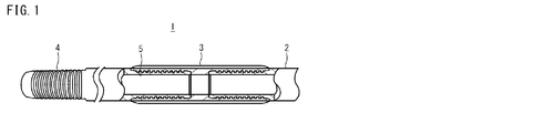
- FIG. 1 is a view showing a configuration of a coupling type pipe threaded joint according to the present embodiment.
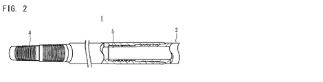
- FIG. 2 is a diagram showing a configuration of an integral type pipe threaded joint according to the present embodiment.
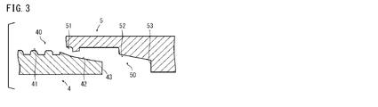
- FIG. 3 is a cross-sectional view of an example of a pipe threaded joint.
- FIG. 4 is a diagram showing a configuration of the pipe threaded joint according to the present embodiment in the case where the pipe has no metal seal portion and no shoulder portion.
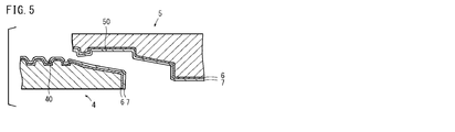
- FIG. 5 is a sectional view of an example of the threaded pipe joint according to the present embodiment.
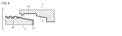
- FIG. 6 is a sectional view of an example of a pipe threaded joint according to another embodiment different from FIG. FIG.
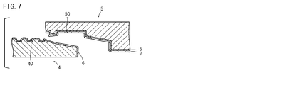
- FIG. 7 is a cross-sectional view of an example of a pipe threaded joint according to another embodiment different from FIGS. 5 and 6.
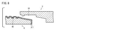
- FIG. 8 is a sectional view of an example of a pipe threaded joint according to another embodiment different from FIGS. 5 to 7.
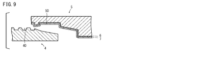
- FIG. 9 is a sectional view of an example of a pipe threaded joint according to another embodiment different from FIGS. 5 to 8.
- the present inventors have further studied a plating layer suitable for a threaded joint for pipes. As a result, the present inventors formed a Ni—W alloy plating layer containing 35.0 to 45.0 mass% of W and the balance of Ni and impurities on the contact surface of the pipe threaded joint, It has been found that the seizure resistance of the threaded joint for pipes during screwing and unscrewing can be improved. Hereinafter, this point will be described.
- the hardness and melting point of a Ni—W alloy containing 35.0 to 45.0% by mass of W and the balance being Ni and impurities are determined by the hardness of a Cu plating layer conventionally used as a plating layer for threaded joints for pipes. And higher than the melting point. Therefore, the Ni—W alloy plating layer containing 35.0 to 45.0% by mass of W and the balance of Ni and impurities has high hardness (Hv 600 or more) and high melting point (1455 ° C. or more). As a result, the use of a Ni-W alloy plating layer containing 35.0 to 45.0% by mass of W and the balance of Ni and impurities increases the seizure resistance of the threaded joint for pipes.
- the present inventors have further studied the thickness of the Ni—W alloy plating layer in detail.
- the pin and box slide frictionally while receiving significantly higher pressure.
- seizure resistance is enhanced even under a high-pressure environment such as when screwing and unscrewing a threaded joint for pipes.
- the threaded joint for pipes of the present embodiment completed based on the above findings includes a pin, a box, a Ni-W alloy plating layer, and a solid lubricating film.
- the pin has a pin-side contact surface that includes a pin-side thread.
- the box has a box side contact surface that includes a box side thread.
- the Ni—W alloy plating layer is disposed on at least one of the pin-side contact surface and the box-side contact surface.
- the Ni—W alloy plating layer is composed of 35.0 to 45.0 mass% of W, and the remainder is composed of Ni and impurities, and has a thickness of 1.0 to 20.0 ⁇ m.
- the solid lubricating coating is disposed on the Ni—W alloy plating layer on at least one of the pin-side contact surface and the box-side contact surface.
- the threaded joint for pipes of the present embodiment contains a Ni-W alloy containing 35.0 to 45.0% by mass of W on at least one of the pin-side contact surface and the box-side contact surface, with the balance being Ni and impurities. It has a plating layer.
- the pipe threaded joint of the present embodiment further has a solid lubricating coating on the Ni—W alloy plating layer on at least one of the pin-side contact surface and the box-side contact surface. Therefore, it has excellent seizure resistance.
- the pin-side contact surface of the pipe threaded joint may further include a pin-side metal seal portion and a pin-side shoulder portion.
- the box side contact surface may further include a box side metal seal and a box side shoulder.
- the method of manufacturing a pipe threaded joint of the present embodiment is a method of forming a Ni—W alloy plating layer on a pipe threaded joint including a pin and a box.
- the pin has a pin-side contact surface that includes a pin-side thread.
- the box has a box side contact surface that includes a box side thread.
- the manufacturing method includes a Ni-W alloy plating layer forming step and a solid lubricating film forming step. In the Ni—W alloy plating layer forming step, at least one of the pin-side contact surface and the box-side contact surface is immersed in a plating solution.
- the plating solution contains nickel ions and tungsten ions.
- a Ni—W alloy plating layer is formed on at least one of the pin-side contact surface and the box-side contact surface.
- the Ni—W alloy plating layer is composed of 35.0 to 45.0 mass% of W, and the remainder is composed of Ni and impurities, and has a thickness of 1.0 to 20.0 ⁇ m.
- a solid lubricant film is formed on the Ni—W alloy plating layer on at least one of the pin-side contact surface and the box-side contact surface.
- the Ni-W alloy plating layer is provided on at least one of the pin-side contact surface and the box-side contact surface, and the Ni-W alloy plating layer is provided on at least one of the pin-side contact surface and the box-side contact surface.
- a threaded joint for pipes having a solid lubricating coating on a W alloy plating layer can be manufactured. Therefore, the threaded pipe joint has excellent seizure resistance.
- the pin-side contact surface may further include a pin-side metal seal portion and a pin-side shoulder portion.
- the box side contact surface may further include a box side metal seal and a box side shoulder.
- FIG. 1 is a diagram showing a configuration of a pipe threaded joint 1 according to the present embodiment.
- a pipe threaded joint 1 includes a steel pipe 2 and a coupling 3.
- Pins 4 each having an external thread portion on the outer surface are formed at both ends of the steel pipe 2.
- Boxes 5 each having a female screw portion on the inner surface are formed at both ends of the coupling 3.
- the coupling 3 is attached to the end of the steel pipe 2 by screwing the pin 4 and the box 5 together.
- a protector may be attached to the pin 4 of the steel pipe 2 and the box 5 of the coupling 3 to which the mating member is not attached in order to protect the respective screw portions.
- FIG. 2 is a diagram showing the configuration of the integral type pipe threaded joint 1 according to the present embodiment.
- the threaded pipe joint 1 includes a steel pipe 2. At one end of the steel pipe 2, a pin 4 having an external thread portion on the outer surface is formed. At the other end of the steel pipe 2, a box 5 having a female screw portion on the inner surface is formed.
- the steel pipes 2 can be connected to each other by screwing the pins 4 and the box 5 together.
- the pipe threaded joint 1 of the present embodiment can be used for both coupling type and integral type pipe threaded joints 1.
- FIG. 3 is a sectional view of an example of the threaded pipe joint 1.
- the pin 4 includes a pin-side screw part 41, a pin-side metal seal part 42, and a pin-side shoulder part 43.
- the box 5 includes a box-side screw portion 51, a box-side metal seal portion 52, and a box-side shoulder portion 53. The portions that come into contact when the pin 4 and the box 5 are screwed together are referred to as contact surfaces 40 and 50.
- the screw portions (the pin-side screw portion 41 and the box-side screw portion 51) and the metal seal portions (the pin-side metal seal portion 42 and the box-side metal seal portion) 52) and the shoulder portions (the pin-side shoulder portion 43 and the box-side shoulder portion 53) come into contact with each other.
- the pin-side contact surface 40 includes a pin-side screw portion 41, a pin-side metal seal portion 42, and a pin-side shoulder portion 43.
- the box-side contact surface 50 includes a box-side screw portion 51, a box-side metal seal portion 52, and a box-side shoulder portion 53.
- the pins 4 are arranged in the order of the pin-side shoulder 43, the pin-side metal seal 42, and the pin-side screw 41 from the end of the steel pipe 2.
- the box-side screw portion 51, the box-side metal seal portion 52, and the box-side shoulder portion 53 are arranged in this order.
- the arrangement of the pin side screw portion 41 and the box side screw portion 51, the pin side metal seal portion 42 and the box side metal seal portion 52, and the arrangement of the pin side shoulder portion 43 and the box side shoulder portion 53 are limited to the arrangement of FIG. However, it can be changed as appropriate. For example, as shown in FIG.
- 43, the pin-side metal seal part 42 and the pin-side screw part 41 may be arranged in this order.
- the seal portion 52 and the box-side shoulder portion 53 may be arranged in this order.
- FIGS. 1 and 2 illustrate a so-called premium joint including a metal seal portion (the pin-side metal seal portion 42 and the box-side metal seal portion 52) and a shoulder portion (the pin-side shoulder portion 43 and the box-side shoulder portion 53).
- the metal seal portion (the pin-side metal seal portion 42 and the box-side metal seal portion 52) and the shoulder portion (the pin-side shoulder portion 43 and the box-side shoulder portion 53) may not be provided.
- FIG. 4 illustrates the pipe threaded joint 1 without the metal seal portions 42 and 52 and the shoulder portions 43 and 53.
- the pipe threaded joint 1 of the present embodiment can be suitably applied to the pipe threaded joint 1 without the metal seal portions 42 and 52 and the shoulder portions 43 and 53.
- the pin-side contact surface 40 includes a pin-side thread 41 and the box-side contact surface 50 includes a box-side thread 51.
- the threaded pipe joint 1 includes a Ni—W alloy plating layer 6 on at least one of the pin-side contact surface 40 and the box-side contact surface 50.
- the threaded pipe joint 1 includes a Ni—W alloy plating layer 6 on both the pin-side contact surface 40 and the box-side contact surface 50.
- the threaded pipe joint 1 further includes a solid lubricating coating 7 on the Ni—W alloy plating layer 6 on at least one of the pin-side contact surface 40 and the box-side contact surface 50.
- the threaded pipe joint 1 includes a solid lubricating coating 7 on both the Ni—W alloy plating layer 6 on the pin-side contact surface 40 and the Ni—W alloy plating layer 6 on the box-side contact surface 50. . If the solid lubricating film 7 is provided on the Ni—W alloy plating layer 6, the lubricating property is enhanced, and the seizure resistance of the threaded pipe joint 1 is further enhanced.
- the arrangement of the alloy plating layers of the present embodiment is not limited to FIG.
- the Ni-W alloy plating layer 6 is provided on both the pin-side contact surface 40 and the box-side contact surface 50, and the Ni-W alloy plating layer 6 on the pin-side contact surface 40 is provided.
- the solid lubricant film 7 may be provided, and the solid lubricant film 7 may not be provided on the Ni—W alloy plating layer 6 on the box-side contact surface 50.
- the Ni-W alloy plating layer 6 is provided on both the pin-side contact surface 40 and the box-side contact surface 50, and the Ni-W alloy plating layer 6 on the box-side contact surface 50 is provided.
- the solid lubricant film 7 may be provided, and the solid lubricant film 7 may not be provided on the Ni—W alloy plating layer 6 on the pin-side contact surface 40. As shown in FIG. 8, the Ni-W alloy plating layer 6 and the solid lubricant film 7 may be provided only on the pin-side contact surface 40. As shown in FIG. 9, the Ni—W alloy plating layer 6 and the solid lubricant film 7 may be provided only on the box-side contact surface 50. Although not shown, the Ni-W alloy plating layer 6 and the solid lubricant film 7 may be provided only on the pin-side contact surface 40, and only the solid lubricant film 7 may be provided on the box-side contact surface 50.
- the Ni-W alloy plating layer 6 and the solid lubricating film 7 may be provided only on the box-side contact surface 50, and only the solid lubricating film 7 may be provided on the pin-side contact surface 40. That is, nothing may be formed on the contact surface where the Ni—W alloy plating layer 6 is not formed, or the solid lubricating film 7 may be formed.
- Another coating for example, a solid anticorrosion coating
- Ni—W alloy plating layer 6 The Ni—W alloy plating layer 6 is disposed on at least one of the pin-side contact surface 40 and the box-side contact surface 50.
- the Ni—W alloy plating layer 6 is made of a Ni—W alloy.
- the Ni—W alloy contains Ni and W, with the balance being impurities.
- the impurities are substances other than Ni and W, and are contained in the Ni—W alloy plating layer 6 during the production of the pipe threaded joint 1 and are contained in a content that does not affect the effects of the present invention. including.
- the impurities are, for example, Fe, S, O, C and the like.
- the hardness and melting point of the Ni—W alloy plating layer 6 are high. Therefore, the seizure resistance of the pipe threaded joint 1 is enhanced.
- the chemical composition of the Ni—W alloy plating layer 6 is 100% by mass, the Ni—W alloy plating layer 6 contains 35.0 to 45.0% by mass of W. In this case, the Ni—W alloy plating layer 6 has high seizure resistance. As a result, the threaded pipe joint 1 exhibits excellent seizure resistance.
- the W content in the Ni—W alloy plating layer 6 is 35.0 to 45.0% by mass.
- a preferable lower limit of the W content in the Ni—W alloy plating layer 6 is 38.0% by mass.
- the preferable upper limit of the W content in the Ni—W alloy plating layer 6 is 42.0% by mass.
- the W content of the Ni—W alloy plating layer 6 is measured by the following method.
- the W content is measured using a handheld X-ray fluorescence spectrometer (DP2000 manufactured by Olympus (trade name: DELTA @ Premium)).
- the composition analysis is performed at any four locations (any 0 °, 90 °, 180 °, or 270 ° location in the circumferential direction of the tube) on the surface of the metal seal portion on which Ni—W has been applied.
- the measured contents of Ni and W are determined by the measurement mode of the alloy.
- the W content (% by mass) is obtained by dividing the measured W content by the total measured Ni and W content.
- the thickness of the Ni—W alloy plating layer 6 is 1.0 to 20.0 ⁇ m. If the thickness of the Ni—W alloy plating layer 6 is less than 1.0 ⁇ m, the seizure resistance decreases. If the thickness of the Ni—W alloy plating layer 6 exceeds 20.0 ⁇ m, the adhesion of the plating decreases.
- the lower limit of the thickness of the Ni—W alloy plating layer 6 is preferably 5.0 ⁇ m, and more preferably 8.0 ⁇ m.
- the upper limit of the thickness of the Ni—W alloy plating layer 6 is preferably 15.0 ⁇ m, and more preferably 12.0 ⁇ m.
- the thickness of the Ni—W alloy plating layer 6 is measured by the following method.
- the contact surface 40 or 50 on which the Ni—W alloy plating layer 6 is formed is brought into contact with a probe of an overcurrent phase type film thickness measuring device conforming to ISO (International Organization for Standardization) 21968 (2005).
- ISO International Organization for Standardization
- the phase difference between the high frequency magnetic field on the input side of the probe and the overcurrent on the Ni—W alloy plating layer 6 excited by the high frequency magnetic field is measured. This phase difference is converted into a thickness of the Ni—W alloy plating layer 6.
- four arbitrary points any 0 °, 90 °, 180 °, 270 ° point in the circumferential direction of the tube) of the contact surface 40 or 50 are measured.
- the pipe threaded joint 1 further includes a solid lubricating coating 7 on the Ni—W alloy plating layer 6 on at least one of the pin-side contact surface 40 and the box-side contact surface 50.
- the lubricity of the pipe threaded joint 1 is further enhanced.
- the solid lubricating film 7 a known material can be used.
- the solid lubricating coating 7 contains, for example, lubricating particles and a binder.
- the solid lubricating coating 7 may contain a solvent and other components as needed.
- the lubricating particles reduce the coefficient of friction of the surface of the solid lubricating coating 7.
- the lubricating particles are not particularly limited as long as they have lubricating properties.
- the lubricating particles are, for example, graphite, MoS 2 (molybdenum disulfide), WS 2 (tungsten disulfide), BN (boron nitride), PTFE (polytetrafluoroethylene), CF x (fluorinated graphite) and CaCO 3 (carbonate Calcium) or one or more selected from the group consisting of:
- graphite, fluorinated graphite, MoS 2 and PTFE are used.
- the preferable content of the lubricating particles is 5 to 40% by mass.
- the binder binds the lubricating particles into the solid lubricating coating 7.
- the binder is, for example, one or two selected from the group consisting of an organic resin and an inorganic resin.
- an organic resin one selected from the group consisting of a thermosetting resin and a thermoplastic resin can be used.
- the thermosetting resin is, for example, one or two selected from the group consisting of an epoxy resin, a polyimide resin, a polycarbodiimide resin, a polyethersulfone, a polyetheretherketone resin, a phenol resin, a furan resin, a urea resin, and an acrylic resin. More than a species.
- the thermoplastic resin is, for example, one or more selected from the group consisting of a polyamideimide resin, a polyethylene resin, a polypropylene resin, a polystyrene resin, and an ethylene vinyl acetate resin. Assuming that the solid lubricating coating 7 is 100% by mass, the preferable content of the binder is 60 to 95% by mass.
- polymetalloxane refers to a polymer compound in which a repeating metal-oxygen bond is a main chain skeleton.
- polytitanoxane (Ti—O) and polysiloxane (Si—O) are used.
- These inorganic resins are obtained by hydrolyzing and condensing a metal alkoxide.
- the alkoxy group of the metal alkoxide is, for example, a lower alkoxy group such as a methoxy group, an ethoxy group, a propoxy group, an isopropoxy group, an isobutoxy group, a butoxy group and a tert-butoxy group.
- the solvent is not particularly limited as long as the components contained in the solid lubricating coating 7 can be dispersed or dissolved.
- the solvent one or two kinds selected from the group consisting of an organic solvent and water can be used.
- the organic solvent is, for example, one or two selected from the group consisting of toluene and isopropyl alcohol.
- the solid lubricating coating 7 can contain other components as needed.
- Other components are, for example, rust inhibitors, corrosion inhibitors, surfactants, waxes, friction modifiers and pigments.
- the content of each of the lubricating particles, the binder, the solvent, and other components is appropriately set.
- a preferable content of other components is, for example, 1 to 50% by mass, and preferably 5 to 30% by mass.
- the chemical composition of the base material of the threaded pipe joint 1 is not particularly limited.
- the base material is, for example, carbon steel, stainless steel, alloy steel, or the like.
- the alloy steel is, for example, a Ni alloy and a duplex stainless steel containing alloy elements such as Cr, Ni and Mo.
- the base material of the pipe threaded joint 1 is, for example, 13% Cr steel (C: 0.18%, Si: 0.23%, Mn: 0.8%, P: 0.02%), which is a kind of high alloy steel. , S: 0.01%, Cu: 0.04%, Ni: 0.1%, Cr: 13%, Mo: 0.04%, balance: Fe and impurities).
- the method for manufacturing the threaded pipe joint 1 of the present embodiment is the method for manufacturing the above-described threaded pipe joint 1.
- the manufacturing method includes a Ni-W alloy plating layer forming step and a solid lubricating film forming step.
- Ni—W alloy plating layer forming step the Ni—W alloy plating layer 6 made of a Ni—W alloy is deposited on at least one of the pin-side contact surface 40 and the box-side contact surface 50 of the prepared pipe threaded joint 1.
- the Ni—W alloy plating layer 6 is formed by electroplating. The electroplating is performed by immersing the pin-side contact surface 40 of the pin 4 or the box-side contact surface 50 of the box 5 as a material to be plated in a plating bath containing Ni ions and W ions, and supplying electricity.
- the plating bath preferably contains Ni ions: 0.13 to 0.3 mol / L and W ions: 0.3 to 0.42 mol / L.
- Electroplating conditions can be set as appropriate.
- the electroplating conditions are, for example, plating bath pH: 1 to 10, plating bath temperature: 10 to 60 ° C., current density: 1 to 100 A / dm 2 , and treatment time: 0.1 to 30 minutes.
- Solid lubrication film forming process The solid lubricating coating 7 is formed on the Ni—W alloy plating layer 6 on at least one of the pin-side contact surface 40 and the box-side contact surface 50.
- a composition for a solid lubricating film (hereinafter, also referred to as a composition) is prepared.
- the composition is formed by mixing the lubricating particles and the binder described above.
- the composition may further contain the above-mentioned solvents and other components.
- the obtained composition is applied on the Ni—W alloy plating layer 6.
- the method of application is not particularly limited.
- the composition is sprayed on the Ni—W alloy plating layer 6 using a spray gun.
- the pin 4 or the box 5 to which the composition has been applied is dried by heating.
- the composition is cured, and a solid lubricating film 7 is formed on the Ni—W alloy plating layer 6.
- the conditions for the heating and drying can be appropriately set in consideration of the boiling point and melting point of each component contained in the composition.
- a hot melt method can be used. In the hot melt method, the composition is heated to a fluid state.
- the composition in a fluidized state is sprayed using, for example, a spray gun having a temperature maintaining function.
- the pin 4 or the box 5 to which the composition has been applied is cooled by air cooling or the like.
- the composition is cured, and a solid lubricating film 7 is formed on the Ni—W alloy plating layer 6.
- a base treatment step may be performed before the Ni—W alloy plating layer forming step, if necessary.
- the undercoating process is, for example, pickling and alkali degreasing.
- oil and the like attached to the contact surface forming the Ni—W alloy plating layer 6 are removed.
- the base treatment step may further include a grinding process such as sandblasting and mechanical grinding. Only one kind of these base treatments may be performed, or a plurality of base treatments may be performed in combination.
- the contact surface of the pin is called the pin surface
- the contact surface of the box is called the box surface.
- % in the examples means mass%.
- the base material is a 13% Cr steel (C: 0.18%, Si: 0.23%, Mn: 0.8%, P: 0.02%, S: 0. 01%, Cu: 0.04%, Ni: 0.1%, Cr: 13%, Mo: 0.04%, balance: Fe and impurities).
- a seamless steel pipe and a coupling were manufactured.
- the size of the seamless steel pipe was 168.28 mm in outer diameter, 12.1 mm in wall thickness, and 1200 mm in length.
- Pins having a male thread portion and a threadless metal contact portion were formed on the outer surfaces of both ends of the seamless steel pipe by cutting.
- a box having a female thread portion and a threadless metal contact portion was formed on the inner surfaces of both ends of the coupling by cutting.
- Ni—W alloy plating layer forming step A Ni—W alloy plating layer was formed on the box surfaces of Test Nos. 1 to 7.
- the Ni—W alloy plating layer was formed by electroplating. Specifically, the coupling was immersed in the plating bath of each test number and energized to form a Ni—W alloy plating layer.
- the plating conditions were as follows: plating bath pH: 5, plating bath temperature: 60 ° C, current density: 20 A / dm 2 (constant current electrolytic method).
- the composition of the plating bath for each test number was as shown in Table 1.
- the plating bath was prepared by dissolving commercially available special grade nickel sulfate heptahydrate, disodium tungstate, and triammonium citrate: 0.6 mol / L in pure water.
- the total metal salt concentration was constant at 0.6 mol / L.
- Several types of plating baths were constructed by changing the ratio of the concentration of disodium tungstate to the concentration of all metal salts.
- CuA Cu—Sn—Zn alloy plating layer was formed on the box surface of Test No. 8. Specifically, a Cu—Sn—Zn alloy plating layer was formed on the box surface by electroplating using a cyan bath containing copper ions, tin ions, and zinc ions. The Cu—Sn—Zn alloy plating layer contained about 7% of Zn, about 40% of Sn, and about 53% of Cu.
- Solid lubrication film forming process A solid lubricating film was further formed on the box surfaces of Test Nos. 1 to 8.
- the composition for forming a solid lubricating film contained polyamideimide resin: 12% by mass, dimethyl sulfoxide: 45% by mass, PTFE particles: 5% by mass, and pure water: balance. After spray-coating this composition on the alloy plating layer, preliminary drying (85 ° C., 10 minutes) and main heating (280 ° C., 30 minutes) were performed to form a solid lubricating film having an average film thickness of 30 ⁇ m.
- the pin surface was subjected to a mechanical grinding finish (surface roughness 3 ⁇ m), and then a solid anticorrosion film was formed.
- the composition for forming a solid anticorrosive film contained an acrylic resin-based UV-curable resin paint, aluminum phosphite, and polyethylene wax. The contents of aluminum phosphite and polyethylene wax were 0.05 and 0.01 with respect to the acrylic resin-based ultraviolet-curable resin 1, respectively.
- the composition was cured by irradiating the composition with ultraviolet rays using a UV lamp (air-cooled mercury lamp, output 4 kW, ultraviolet wavelength: 260 nm).
- the thickness of the solid anticorrosion coating was 25 ⁇ m.
- the pipe threaded joint of Test No. 8 was provided with a conventional Cu-Sn-Zn alloy plating layer. Therefore, seizure occurred in the pipe threaded joint of Test No. 8 when the screw tightening and unscrewing were repeated seven times.
Landscapes
- Engineering & Computer Science (AREA)
- General Engineering & Computer Science (AREA)
- Mechanical Engineering (AREA)
- Non-Disconnectible Joints And Screw-Threaded Joints (AREA)
- Electroplating Methods And Accessories (AREA)
Abstract
La présente invention concerne un raccord vissé (1) qui est destiné à un tube et qui présente une excellente résistance au grippage. Le raccord vissé (1) pour tube selon le présent mode de réalisation comprend une extrémité mâle (4), une extrémité femelle (5), une couche (6) de placage en alliage Ni-W, et un film lubrifiant solide (7). L'extrémité mâle (4) présente une surface (40) de contact côté mâle qui comprend une partie filetée (41) côté mâle. L'extrémité femelle (5) présente une surface (50) de contact côté femelle qui comprend une partie filetée (51) côté femelle. La couche (6) de placage en alliage Ni-W est disposée sur au moins une surface parmi la surface (40) de contact côté mâle et la surface (50) de contact côté femelle. La couche (6) de placage en alliage Ni-W est composée de 35,0 à 45,0% en masse de W, le reste étant constitué de Ni et d'impuretés, et présente une épaisseur de 1,0 à 20,0 μm. Le film lubrifiant solide (7) est disposé sur la couche (6) de placage en alliage Ni-W sur au moins une surface parmi la surface (40) de contact côté mâle et la surface (50) de contact côté femelle.
Priority Applications (1)
| Application Number | Priority Date | Filing Date | Title |
|---|---|---|---|
| PCT/JP2018/028165 WO2020021691A1 (fr) | 2018-07-27 | 2018-07-27 | Raccord vissé pour tube et procédé de fabrication d'un raccord vissé pour tube |
Applications Claiming Priority (1)
| Application Number | Priority Date | Filing Date | Title |
|---|---|---|---|
| PCT/JP2018/028165 WO2020021691A1 (fr) | 2018-07-27 | 2018-07-27 | Raccord vissé pour tube et procédé de fabrication d'un raccord vissé pour tube |
Publications (1)
| Publication Number | Publication Date |
|---|---|
| WO2020021691A1 true WO2020021691A1 (fr) | 2020-01-30 |
Family
ID=69181483
Family Applications (1)
| Application Number | Title | Priority Date | Filing Date |
|---|---|---|---|
| PCT/JP2018/028165 Ceased WO2020021691A1 (fr) | 2018-07-27 | 2018-07-27 | Raccord vissé pour tube et procédé de fabrication d'un raccord vissé pour tube |
Country Status (1)
| Country | Link |
|---|---|
| WO (1) | WO2020021691A1 (fr) |
Cited By (2)
| Publication number | Priority date | Publication date | Assignee | Title |
|---|---|---|---|---|
| CN114633487A (zh) * | 2022-02-08 | 2022-06-17 | 厦门建霖健康家居股份有限公司 | 一种塑料复合结构及其连接方式 |
| CN115968420A (zh) * | 2020-08-27 | 2023-04-14 | 日本制铁株式会社 | 油井用金属管 |
Citations (4)
| Publication number | Priority date | Publication date | Assignee | Title |
|---|---|---|---|---|
| JPS6026695A (ja) * | 1983-07-26 | 1985-02-09 | Sumitomo Metal Ind Ltd | 油井管継ぎ手 |
| JP2016540884A (ja) * | 2013-10-02 | 2016-12-28 | ヴァルレック オイル アンド ガス フランス | 金属複合析出物で覆われた管状コンポーネントの当接構造およびその製造方法 |
| WO2017110686A1 (fr) * | 2015-12-25 | 2017-06-29 | 新日鐵住金株式会社 | Joint à vis pour tube et procédé de fabrication de celui-ci |
| JP2018123349A (ja) * | 2017-01-30 | 2018-08-09 | 新日鐵住金株式会社 | 管用ねじ継手及び管用ねじ継手の製造方法 |
-
2018
- 2018-07-27 WO PCT/JP2018/028165 patent/WO2020021691A1/fr not_active Ceased
Patent Citations (4)
| Publication number | Priority date | Publication date | Assignee | Title |
|---|---|---|---|---|
| JPS6026695A (ja) * | 1983-07-26 | 1985-02-09 | Sumitomo Metal Ind Ltd | 油井管継ぎ手 |
| JP2016540884A (ja) * | 2013-10-02 | 2016-12-28 | ヴァルレック オイル アンド ガス フランス | 金属複合析出物で覆われた管状コンポーネントの当接構造およびその製造方法 |
| WO2017110686A1 (fr) * | 2015-12-25 | 2017-06-29 | 新日鐵住金株式会社 | Joint à vis pour tube et procédé de fabrication de celui-ci |
| JP2018123349A (ja) * | 2017-01-30 | 2018-08-09 | 新日鐵住金株式会社 | 管用ねじ継手及び管用ねじ継手の製造方法 |
Cited By (2)
| Publication number | Priority date | Publication date | Assignee | Title |
|---|---|---|---|---|
| CN115968420A (zh) * | 2020-08-27 | 2023-04-14 | 日本制铁株式会社 | 油井用金属管 |
| CN114633487A (zh) * | 2022-02-08 | 2022-06-17 | 厦门建霖健康家居股份有限公司 | 一种塑料复合结构及其连接方式 |
Similar Documents
| Publication | Publication Date | Title |
|---|---|---|
| JP6815498B2 (ja) | 管用ねじ継手及び管用ねじ継手の製造方法 | |
| JP6368868B2 (ja) | 管用ねじ継手及び管用ねじ継手の製造方法 | |
| JP6949968B2 (ja) | 管用ねじ継手及び管用ねじ継手の製造方法 | |
| CN101300443B (zh) | 钢管用螺纹接头及其销和壳体 | |
| JP6964678B2 (ja) | 管用ねじ継手及び管用ねじ継手の製造方法 | |
| WO2018003455A1 (fr) | Raccord à vis destiné à un tuyau et procédé de fabrication de raccord à vis destiné à un tuyau | |
| WO2020149310A1 (fr) | Joint fileté pour tuyaux et procédé de production d'un joint fileté pour tuyaux | |
| WO2020021691A1 (fr) | Raccord vissé pour tube et procédé de fabrication d'un raccord vissé pour tube | |
| JP6918103B2 (ja) | 油井管用ねじ継手及び油井管用ねじ継手の製造方法 | |
| JP2018123346A (ja) | 管用ねじ継手及びその製造方法 | |
| JP2018123349A (ja) | 管用ねじ継手及び管用ねじ継手の製造方法 | |
| JP2018123831A (ja) | 管用ねじ継手及び管用ねじ継手の製造方法 | |
| WO2020021710A1 (fr) | Joint à vis pour tuyau et procédé de fabrication d'un joint à vis pour tuyau | |
| JP7734764B2 (ja) | 油井用金属管 | |
| JP7781172B2 (ja) | 油井用金属管 | |
| WO2020021704A1 (fr) | Joint à vis pour tuyau et son procédé de fabrication | |
| WO2023063384A1 (fr) | Tuyau métallique pour puits de pétrole | |
| OA18803A (en) | Threaded joint for pipe, and manufacturing method of threaded joint for pipe. | |
| OA20066A (en) | Pipe threaded joint, and method for producing pipe threaded joint. | |
| OA20120A (en) | Threaded joint for pipes and method for producing threaded joint for pipes. |
Legal Events
| Date | Code | Title | Description |
|---|---|---|---|
| 121 | Ep: the epo has been informed by wipo that ep was designated in this application |
Ref document number: 18927712 Country of ref document: EP Kind code of ref document: A1 |
|
| NENP | Non-entry into the national phase |
Ref country code: DE |
|
| 122 | Ep: pct application non-entry in european phase |
Ref document number: 18927712 Country of ref document: EP Kind code of ref document: A1 |
|
| NENP | Non-entry into the national phase |
Ref country code: JP |