WO2020021708A1 - Appareil de filtration à double crépine - Google Patents
Appareil de filtration à double crépine Download PDFInfo
- Publication number
- WO2020021708A1 WO2020021708A1 PCT/JP2018/028274 JP2018028274W WO2020021708A1 WO 2020021708 A1 WO2020021708 A1 WO 2020021708A1 JP 2018028274 W JP2018028274 W JP 2018028274W WO 2020021708 A1 WO2020021708 A1 WO 2020021708A1
- Authority
- WO
- WIPO (PCT)
- Prior art keywords
- strainer
- valve body
- filtration chamber
- filtration
- fluid
- Prior art date
- Legal status (The legal status is an assumption and is not a legal conclusion. Google has not performed a legal analysis and makes no representation as to the accuracy of the status listed.)
- Ceased
Links
Images






Classifications
-
- B—PERFORMING OPERATIONS; TRANSPORTING
- B01—PHYSICAL OR CHEMICAL PROCESSES OR APPARATUS IN GENERAL
- B01D—SEPARATION
- B01D24/00—Filters comprising loose filtering material, i.e. filtering material without any binder between the individual particles or fibres thereof
- B01D24/48—Filters comprising loose filtering material, i.e. filtering material without any binder between the individual particles or fibres thereof integrally combined with devices for controlling the filtration
-
- B—PERFORMING OPERATIONS; TRANSPORTING
- B01—PHYSICAL OR CHEMICAL PROCESSES OR APPARATUS IN GENERAL
- B01D—SEPARATION
- B01D29/00—Filters with filtering elements stationary during filtration, e.g. pressure or suction filters, not covered by groups B01D24/00 - B01D27/00; Filtering elements therefor
- B01D29/60—Filters with filtering elements stationary during filtration, e.g. pressure or suction filters, not covered by groups B01D24/00 - B01D27/00; Filtering elements therefor integrally combined with devices for controlling the filtration
-
- B—PERFORMING OPERATIONS; TRANSPORTING
- B01—PHYSICAL OR CHEMICAL PROCESSES OR APPARATUS IN GENERAL
- B01D—SEPARATION
- B01D29/00—Filters with filtering elements stationary during filtration, e.g. pressure or suction filters, not covered by groups B01D24/00 - B01D27/00; Filtering elements therefor
- B01D29/62—Regenerating the filter material in the filter
-
- B—PERFORMING OPERATIONS; TRANSPORTING
- B01—PHYSICAL OR CHEMICAL PROCESSES OR APPARATUS IN GENERAL
- B01D—SEPARATION
- B01D35/00—Filtering devices having features not specifically covered by groups B01D24/00 - B01D33/00, or for applications not specifically covered by groups B01D24/00 - B01D33/00; Auxiliary devices for filtration; Filter housing constructions
- B01D35/02—Filters adapted for location in special places, e.g. pipe-lines, pumps, stop-cocks
Definitions
- the present invention relates to a double strainer type filter.
- the present invention relates to a structure of a double strainer type filter in which a set of strainers is arranged in parallel inside a casing via a partition wall.
- thermal power plants use a large amount of seawater or river water to cool a plurality of cooling pipes arranged inside a condenser.
- seawater or river water contains various foreign substances such as shellfish and algae, a filter is provided in a cooling water intake system such as seawater to collect these foreign substances.
- such a filter is of a type in which a strainer made of a filter net is disposed inside a casing and water is passed through the strainer to remove foreign matter.
- the strainer may be clogged with foreign matter, or the foreign matter may stay inside the strainer, which may reduce the water supply capacity to the condenser. .
- the operation of the thermal power plant may stagnate.
- FIG. 10 is a plan view showing a configuration of a conventional double strainer type filter, and shows a main part in a cross-sectional view.
- FIG. 11 is a left side view showing a configuration of a conventional double strainer type filter, and shows a main part in a longitudinal sectional view.
- FIG. 12 is a front view showing a configuration of a conventional double strainer type filter. 10 to 12 of the present application correspond to FIGS. 1 to 3 of Patent Document 1.
- a conventional double strainer type filter (hereinafter abbreviated as a filter) 9 includes a casing 1 and a pair of truncated cylindrical strainers 8.8.
- the casing 1 includes a casing main body 11, an upstream bonnet 12, and a downstream bonnet 13. Further, the casing 1 includes a pair of disc-shaped top covers 14a and 14b and a pair of cylindrical bottom covers 15a and 15b.
- the casing main body 11 has a pair of filtration chambers Ra and Rb partitioned by a partition wall Bh formed therein in parallel. Strainers 8.8 are installed in these filtration chambers Ra and Rb.
- the upstream bonnet 12 is attached to one end surface of the casing body 11.
- the upstream bonnet 12 has an opening inside so as to easily conduct a fluid such as seawater flowing from the upstream Su side.
- the upstream bonnet 12 circulates the fluid guided from the upstream Su side to the filtration chamber Ra or the filtration chamber Rb.
- the downstream bonnet 13 is attached to the other end surface of the casing body 11.
- the downstream side bonnet 13 is open inside so that a fluid such as seawater flowing from the filtration chamber Ra or the filtration chamber Rb can easily flow out. Then, the downstream bonnet 13 can flow the fluid to the downstream Sd side in a state where the fluid flowing from the filtration chamber Ra or the filtration chamber Rb captures foreign matter.
- the pair of top covers 14a and 14b are detachably fixed to the upper surface of the casing body 11.
- One top cover 14a seals the upper opening of the filtration chamber Ra.
- the strainer 8 installed in the filtration chamber Ra can be taken out. Then, foreign matter remaining on the strainer 8 can be removed.
- the other top cover 14b seals the upper opening of the filtration chamber Rb.
- the strainer 8 installed in the filtration chamber Rb can be taken out. Then, foreign matter remaining on the strainer 8 can be removed.
- the top cover 14a and the top cover 14b are the same, they are distinguished by changing reference numerals for convenience of explanation.
- the pair of bottom covers 15 a and 15 b are fixed to the bottom surface of the casing body 11.
- the pair of bottom covers 15a and 15b constitute a part of the filtration chambers Ra and Rb.
- the pair of bottom covers 15a and 15b have bottom plates 151 attached to the bottoms, respectively.
- the pair of bottom covers 15a and 15b fix a pair of stands 17 and 17 to their outer periphery.
- the filter 9 can be supported on the installation surface.
- the filter 9 includes a communication tube 16.
- the communication tube 16 communicates the bottom cover 15a and the bottom cover 15b.
- a gate valve 16v is provided on the path of the communication tube 16. When the gate valve 16v is opened, the fluid in the filtration chamber Ra and the fluid in the filtration chamber Rb can mutually flow. When the gate valve 16v is closed, the flow of the fluid in the filtration chamber Ra and the fluid in the filtration chamber Rb can be shut off.
- the filter 9 further includes an upstream valve body 3 and a downstream valve body 4.
- the upstream valve body 3 is disposed between the upstream bonnet 12 and one end surface of the casing body 11.
- the upstream valve body 3 is arranged to be able to reciprocate between the filtration chamber Ra and the filtration chamber Rb by a first screw feed mechanism 1Ms described later.
- the downstream valve body 4 is arranged between the downstream bonnet 13 and the other end surface of the casing body 11.
- the downstream side valve element 4 is arranged to be able to reciprocate between the filtration chamber Ra and the filtration chamber Rb by a second screw feed mechanism 2Ms described later.
- the upstream valve body 3 closes the inflow port 1 Kb of the filtration chamber Rb so that the upstream valve body 3 circulates from the upstream Su side. Flowing fluid into the filtration chamber Rb can be prevented.
- the upstream valve 3 moves to the filtration chamber Rb, the upstream valve 3 opens the inlet 1Ka of the filtration chamber Ra, so that the fluid flowing from the upstream Su side can flow into the filtration chamber Ra.
- the upstream valve body 3 in a state where the upstream valve body 3 has moved to the filtration chamber Ra side, the upstream valve body 3 can open the inflow port 1 Kb of the filtration chamber Rb, and the upstream valve body 3 The inlet 1Ka of the chamber Ra can be closed.
- downstream valve element 4 when downstream valve element 4 is moved to filtration chamber Rb side, downstream valve element 4 closes outflow port 2Kb of filtration chamber Rb to be accommodated in filtration chamber Rb. It is possible to prevent the drained fluid from flowing to the downstream Sd side.
- the downstream valve body 4 In a state where the downstream valve body 4 has moved to the filtration chamber Rb side, the downstream valve body 4 opens the outflow port 2Ka of the filtration chamber Ra, so that the fluid flowing from the upstream Su side through the filtration chamber Ra is filtered. It can flow to the downstream Sd side.
- the downstream valve body 4 in a state where the downstream valve body 4 has moved to the filtration chamber Ra side, the downstream valve body 4 can open the outlet 2Ka of the filtration chamber Rb, and the downstream valve body 4 The outlet 2Ka of the chamber Ra can be closed.
- the filter 9 includes a first screw feed mechanism 1Ms and a second screw feed mechanism 2Ms.
- the first screw feed mechanism 1Ms can reciprocate the upstream valve body 3 between the filtration chamber Ra and the filtration chamber Rb.
- the second screw feed mechanism 2Ms can reciprocate the downstream valve body 4 between the filtration chamber Ra and the filtration chamber Rb.
- the configuration of the screw feed mechanism will be mainly described as a representative of the second screw feed mechanism 2Ms.
- the second screw feed mechanism 2Ms includes a feed screw Sf, a gear box Bg, and a handle Hd. Both ends of the feed screw Sf are rotatably held by the downstream bonnet 13.
- the feed screw Sf is screwed with a female screw portion 41 protruding on the back side of the downstream valve body 4. When the feed screw Sf is rotated, the downstream valve body 4 can be moved along the feed screw Sf.
- both ends of the feed screw Sf are rotatably held by the upstream bonnet 12.
- the feed screw Sf is screwed with a female screw portion 31 protruding on the back side of the upstream valve body 3.
- the upstream valve element 3 can be moved along the feed screw Sf.
- the gear box Bg includes a set of bevel gears (not shown) that mesh with each other.
- One bevel gear (not shown) is fixed to the center axis of the handle Hd.
- the other bevel gear (not shown) is fixed to an extension shaft of the feed screw Sf.
- a pair of bevel gears (not shown) can transmit the rotation of the handle Hd to the feed screw Sf.
- the filter 9 further includes a connecting rod Rc.
- the connecting rod Rc is arranged between a pair of gear boxes Bg.
- the connecting rod Rc can transmit the rotation of one handle Hd to the other handle Hd.
- the upstream valve body 3 and the downstream valve body 4 can move to the filtration chamber Ra side in conjunction with each other. Then, the openings at both ends of the filtration chamber Ra can be closed.
- the upstream valve body 3 and the downstream valve body 4 can be linked to move to the filtration chamber Rb side. Then, the openings at both ends of the filtration chamber Rb can be closed.
- the filter 9 rotates the one handle Hd or the other handle Hd in the normal or reverse direction, so that the upstream valve body 3 and the downstream valve body 4 move in conjunction with each other, and the filtration chamber Ra or the filtration chamber
- the inlets 1Ka and 1Kb and the outlets 2Ka and 2Kb of the chamber Rb can be selectively opened and closed.
- the strainer 8 has an upper surface opened and an outer periphery formed by a wire mesh 81 or the like.
- the strainer 8 has a bottom surface formed of a perforated plate 82. Further, the strainer 8 is provided with a U-shaped lifting handle 83 at the upper part.
- the fluid flowing from the upstream Su side passes through the strainer 8 arranged in the filtration chamber Ra. After flowing through the inside from the upper surface and collecting foreign matter inside the strainer 8, the foreign matter can flow out to the downstream Sd side. Then, the fluid in which the foreign matters are collected can be supplied as a cooling medium to, for example, a condenser.
- the top cover 14a is removed from the casing body 11 (see FIG. 12), and the ceiling is removed.
- the strainer 8 disposed inside the filtration chamber Ra is lifted to remove foreign matter.
- the present invention has been made in view of such a problem, and is a double strainer-type filter that can maintain the other strainer when one of the strainers is filtering foreign substances.
- An object of the present invention is to provide a double strainer-type filter capable of easily removing remaining foreign matter.
- the present inventor connects a drain pipe to the bottom of the strainer to enable foreign substances to be collected from the strainer and to enable backwashing from the outer periphery of the strainer to the inside, thereby easily removing foreign substances remaining on the strainer.
- a drain pipe to the bottom of the strainer to enable foreign substances to be collected from the strainer and to enable backwashing from the outer periphery of the strainer to the inside, thereby easily removing foreign substances remaining on the strainer.
- a double-strainer type filter according to the present invention has a pair of filtration chambers, one end of which is opened so that a fluid can be introduced from an upstream side, the other end is easily opened so that a fluid can easily flow to a downstream side, and the partition is partitioned by a partition.
- a set of drain pipes, and a gate valve disposed on the way of the drain pipe and capable of opening and closing a state of discharging fluid from the filtration chamber and a state of preventing discharge of fluid from the filtration chamber are provided.
- the inlet of one of the filtration chambers is closed, the outlet of one of the filtration chambers is partially opened, and the other one is opened.
- One of the filtration chambers that is backwashing the strainer opens a gate valve of one of the drainage pipes, and the other filtration chamber that passes through the strainer is connected to the other of the drainage pipes.
- the gate valve is closed.
- a collection basket capable of collecting only foreign matter contained in the fluid discharged from the drain pipe is disposed at a tip end of the drain pipe.
- the strainer is open on the upper surface, a water introduction opening for introducing a fluid, a wire mesh forming an outer periphery and collecting foreign substances contained in the fluid, a perforated plate forming a bottom surface, and a bottom portion of the perforated plate. And a tray that is disposed below the plate and faces the central opening of the perforated plate.
- the inlet of one filtration chamber is closed, and the outlet of one filtration chamber is partially closed.
- the strainer disposed in one of the filtration chambers can be backwashed by allowing the fluid to flow into one of the filtration chambers from the outlet of the other filtration chamber. This makes it possible to easily remove foreign matter remaining on the strainer without lifting the strainer from the casing.
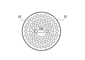
- FIG. 5 is a sectional view taken along the line AA in FIG. 4.
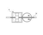
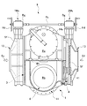
- FIG. 3 is a partial front view showing a configuration of the double strainer type filter according to the embodiment, in which a downstream valve element partially opens an outlet of one filtration chamber and substantially opens an outlet of another filtration chamber.
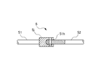
- FIG. It is the front view to which the switching mechanism with which the double strainer type filter by the said embodiment was equipped was expanded, and the state in which the connection of one connecting rod and the other connecting rod was cancelled.
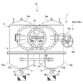
- a double strainer type filter (hereinafter, abbreviated as a filter) 10 includes a casing 1 and a pair of truncated cylindrical strainers 2. I have.
- the casing 1 includes a casing main body 11, an upstream bonnet 12, and a downstream bonnet 13. Further, the casing 1 includes a pair of disc-shaped top covers 14a and 14b and a pair of cylindrical bottom covers 15a and 15b.
- the casing main body 11 has a pair of filtration chambers Ra and Rb partitioned by a partition wall Bh formed therein in parallel. Strainers 2 are installed in these filtration chambers Ra and Rb.
- the upstream bonnet 12 is attached to one end face of the casing body 11.
- the upstream bonnet 12 has an opening inside so as to easily conduct a fluid such as seawater flowing from the upstream Su side.
- the upstream bonnet 12 circulates the fluid guided from the upstream Su side to the filtration chamber Ra or the filtration chamber Rb.
- the downstream bonnet 13 is attached to the other end surface of the casing body 11.
- the downstream side bonnet 13 is open inside so that a fluid such as seawater flowing from the filtration chamber Ra or the filtration chamber Rb can easily flow out. Then, the downstream bonnet 13 can flow the fluid to the downstream Sd side in a state where the fluid flowing from the filtration chamber Ra or the filtration chamber Rb captures foreign matter.
- the casing 1 has one end opened so that the fluid can be guided from the upstream side and the other end opened so that the fluid can easily flow out to the downstream side.
- the casing 1 has a pair of filtration chambers Ra and Rb partitioned by a partition wall Bh formed therein in parallel.
- the pair of top covers 14 a and 14 b is detachably fixed to the upper surface of the casing body 11.
- One top cover 14a seals the upper opening of the filtration chamber Ra.
- the strainer 2 installed in the filtration chamber Ra can be taken out. Then, foreign matter remaining on the strainer 2 can be removed.
- the strainer 2 installed in the filtration chamber Ra can remove foreign matters remaining on the strainer 2 by backwashing, as described later, so that the one top cover 14a is removed. Is unnecessary.
- the other top cover 14b seals the upper opening of the filtration chamber Rb.
- the strainer 2 installed in the filtration chamber Rb can be taken out. Then, foreign matter remaining on the strainer 2 can be removed.
- the pair of bottom covers 15 a and 15 b is fixed to the bottom surface of the casing body 11.
- the pair of bottom covers 15a and 15b constitute a part of the filtration chambers Ra and Rb.
- the pair of bottom covers 15a and 15b have bottom plates 152 attached to the bottoms, respectively.
- the bottom plate 152 has a hole communicating with the outlet 15v at the center.
- a pair of drain pipes 18 is disposed at the bottoms of the pair of filtration chambers Ra and Rb.
- the base end of the drain pipe 18 is fixed to the bottom plate 152.
- a gate valve 18v that can open and close the flow path of the drain pipe 18 is disposed on the way of the drain pipe 18.
- a collection basket 19 is disposed at the tip of the drain pipe 18.
- the collection basket 19 can collect foreign matter contained in the fluid discharged from the drain pipe 18.
- the filter 10 further includes an upstream valve body 3 and a downstream valve body 4.
- the upstream valve body 3 is disposed between the upstream bonnet 12 and one end surface of the casing body 11.
- the upstream valve body 3 is arranged to be able to reciprocate between the filtration chamber Ra and the filtration chamber Rb by the first screw feed mechanism 1Ms.
- the downstream valve body 4 is disposed between the downstream bonnet 13 and the other end face of the casing body 11.
- the downstream valve element 4 is arranged so as to be able to reciprocate between the filtration chamber Ra and the filtration chamber Rb by the second screw feed mechanism 2Ms.
- the filter 10 includes a first screw feed mechanism 1Ms and a second screw feed mechanism 2Ms.
- the first screw feed mechanism 1Ms can reciprocate the upstream valve body 3 between the filtration chamber Ra and the filtration chamber Rb.
- the second screw feed mechanism 2Ms can reciprocate the downstream valve body 4 between the filtration chamber Ra and the filtration chamber Rb.
- the first screw feed mechanism 1Ms includes a feed screw Sf, a gear box Bg, and a handle Hd. Both ends of the feed screw Sf are rotatably held by the upstream bonnet 12. Further, the feed screw Sf is screwed with a female screw portion 41 protruding on the back side of the upstream valve body 3. When the feed screw Sf is rotated, the upstream valve element 3 can be moved along the feed screw Sf.
- the second screw feed mechanism 2Ms includes a feed screw Sf, a gear box Bg, and a handle Hd. Both ends of the feed screw Sf are rotatably held by the downstream bonnet 13.
- the feed screw Sf is screwed with a female screw portion 41 protruding on the back side of the downstream valve body 4. When the feed screw Sf is rotated, the downstream valve body 4 can be moved along the feed screw Sf.
- the filter 10 further includes a switching mechanism 5.
- the switching mechanism 5 is disposed between the gear box Bg of the first screw feed mechanism 1Ms and the gear box Bg of the second screw feed mechanism 2Ms.
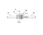
- the switching mechanism 5 includes a first connecting rod 51, a second connecting rod 52, and a wing bolt 5b.
- One end of the first connecting rod 51 is connected to the center axis of one handle Hd. When one of the handles Hd is rotated, the rotation can be transmitted to the first connecting rod 51.
- the other end of the second connecting rod 52 is connected to the central axis of the other handle Hd.
- the rotation can be transmitted to the second connecting rod 52.
- the first connecting rod 51 has a large-diameter joint portion 51j at the other end.
- the joint portion 51j has a hole 51h into which one end of the second connecting rod 52 can be introduced and fitted.
- the joint portion 51j has an insertion hole through which the screw portion 5ms of the wing bolt 5b can be inserted in the outer peripheral direction.
- the joint portion 51j is provided with a female screw portion that can be screwed with the screw portion 5ms of the wing bolt 5b coaxially with the insertion hole.
- an insertion hole through which the screw portion 5ms of the wing bolt 5b can be inserted is opened in the outer peripheral direction.
- screw thread 5 ms of wing bolt 5 b is fastened to the female thread of joint 51 j in a state where the insertion hole of joint 51 j and the insertion hole of one end of second connecting rod 52 are aligned.
- the first connecting rod 51 and the second connecting rod 52 can be integrally rotated around their axes. That is, the upstream valve body 3 and the downstream valve body 4 can be moved synchronously.
- the switching mechanism 5 moves the upstream valve body 3 and the downstream valve body 4 synchronously, or moves the upstream valve body 3 and the downstream valve body 3 to the downstream side.
- the state in which the valve bodies 4 are moved independently of each other can be switched.
- the strainer 2 has a water introduction opening 21 and a wire mesh 22.
- the water introduction opening 21 opens on the upper surface of the strainer 2 and can guide the fluid.
- the wire mesh 22 forms the outer periphery of the strainer 2 and can collect foreign substances contained in the fluid.
- the strainer 2 has a circular perforated plate 23 and a hat-shaped saucer 24.
- the perforated plate 23 has a plurality of holes through which foreign substances having a relatively large specific gravity can pass (see FIG. 5).
- the pan 24 is arranged below the bottom of the perforated plate 23.
- the receiving tray 24 faces the central opening 23h of the perforated plate 23.
- the strainer 2 has a U-shaped spring handle 25 provided on the upper part.
- the strainer 2 By installing the strainer 2 on the bottom cover 15a and fixing the top cover 14a to the casing body 11, the strainer 2 can be pressed against the bottom of the bottom cover 15a by the spring action of the spring handle 25.
- the strainer 2 By installing the strainer 2 on the bottom cover 15b and fixing the top cover 14b to the casing body 11, the strainer 2 can be pressed against the bottom of the bottom cover 15b by the spring action of the spring handle 25.
- one handle Hd is rotated to close the inflow port 1Ka of the one filtration chamber Ra. Further, the other handle Hd is rotated to partially open the outflow port 2Ka of the one filtration chamber Ra (see FIG. 1 or FIG. 7).
- the filter 10 in a state where the upstream valve body 3 and the downstream valve body 4 are moved independently of each other, the filter 10 according to the embodiment closes the inflow port 1Ka of one filtration chamber Ra.
- the strainer disposed in the one filtration chamber Ra is formed. 2 can be backwashed. This makes it possible to easily remove foreign matter remaining on the strainer 2 without lifting the strainer 2 from the casing 1.
- one filtration chamber Ra that is backwashing strainer 2 opens gate valve 18v of one drain pipe 18, and the other filtration chamber Rb through which strainer 2 flows. It is preferable that the gate valve 18v of the other drain pipe 18 is closed. Thereby, the fluid containing foreign matter can be discharged from one of the filtration chambers Ra in which the strainer 2 is backwashed.
- the collection basket 19 is disposed at the tip of the drain pipe 18, only the foreign matter contained in the fluid discharged from the drain pipe 18 is removed. Can be collected.
- the double strainer type filter according to the present invention can expect the following effects. (1) The cost for cleaning the strainer can be reduced. (2) The number of orders for strainer cleaning work can be reduced. (3) The cleaning operation of the strainer can be performed by the internal operator, and the cleaning operation of the strainer can be performed without being restricted by time.
Landscapes
- Chemical & Material Sciences (AREA)
- Chemical Kinetics & Catalysis (AREA)
- Filtration Of Liquid (AREA)
Abstract
L'invention concerne un appareil de filtration à double crépine au moyen duquel il est possible d'éliminer facilement une matière étrangère restante dans une crépine. L'invention concerne un appareil de filtration 10 qui comprend un mécanisme de commutation 5 disposé entre un premier mécanisme d'avance de vis Ms et un second mécanisme d'avance de vis Ms, le mécanisme de commutation 5 étant capable de commuter entre un état dans lequel un corps de vanne 3 côté amont et un corps de vanne 4 côté aval sont amenés à se déplacer de manière synchronisée et un état dans lequel le corps de vanne 3 côté amont et le corps de vanne 4 côté aval sont amenés à se déplacer indépendamment l'un de l'autre, l'appareil de filtration 10 étant tel que, dans l'état où le corps de vanne 3 côté amont et le corps de vanne 4 côté aval sont amenés à se déplacer indépendamment l'un de l'autre, une ouverture d'entrée 1 Ka d'une chambre de filtration Ra est fermée, une ouverture de sortie 2 Ka de la chambre de filtration Ra est partiellement ouverte, et un fluide est amené à s'écouler à partir d'une ouverture de sortie 2 Kb d'une autre chambre de filtration Rb dans la chambre de filtration Ra, ce qui permet un lavage à contre-courant d'une crépine 2 disposée dans la chambre de filtration Ra. L'invention permet d'effectuer un nettoyage sans retirer la crépine 2 du boîtier 1.
Priority Applications (2)
| Application Number | Priority Date | Filing Date | Title |
|---|---|---|---|
| JP2018562141A JP6468411B1 (ja) | 2018-07-27 | 2018-07-27 | ダブルストレーナ型濾過機 |
| PCT/JP2018/028274 WO2020021708A1 (fr) | 2018-07-27 | 2018-07-27 | Appareil de filtration à double crépine |
Applications Claiming Priority (1)
| Application Number | Priority Date | Filing Date | Title |
|---|---|---|---|
| PCT/JP2018/028274 WO2020021708A1 (fr) | 2018-07-27 | 2018-07-27 | Appareil de filtration à double crépine |
Publications (1)
| Publication Number | Publication Date |
|---|---|
| WO2020021708A1 true WO2020021708A1 (fr) | 2020-01-30 |
Family
ID=65356015
Family Applications (1)
| Application Number | Title | Priority Date | Filing Date |
|---|---|---|---|
| PCT/JP2018/028274 Ceased WO2020021708A1 (fr) | 2018-07-27 | 2018-07-27 | Appareil de filtration à double crépine |
Country Status (2)
| Country | Link |
|---|---|
| JP (1) | JP6468411B1 (fr) |
| WO (1) | WO2020021708A1 (fr) |
Families Citing this family (1)
| Publication number | Priority date | Publication date | Assignee | Title |
|---|---|---|---|---|
| CN110075585B (zh) * | 2019-05-07 | 2020-11-13 | 哈尔滨三幸水处理设备制造有限公司 | 一种机械过滤器 |
Citations (5)
| Publication number | Priority date | Publication date | Assignee | Title |
|---|---|---|---|---|
| JPS5167470U (fr) * | 1974-11-25 | 1976-05-28 | ||
| JPS51103359A (fr) * | 1975-03-10 | 1976-09-11 | Hitachi Ltd | |
| JPS5257378U (fr) * | 1975-10-24 | 1977-04-25 | ||
| JPH09303614A (ja) * | 1996-05-15 | 1997-11-28 | Tlv Co Ltd | 弁部材内蔵型ストレ―ナ |
| JP2005288311A (ja) * | 2004-03-31 | 2005-10-20 | Hisaka Works Ltd | ストレーナ |
-
2018
- 2018-07-27 WO PCT/JP2018/028274 patent/WO2020021708A1/fr not_active Ceased
- 2018-07-27 JP JP2018562141A patent/JP6468411B1/ja active Active
Patent Citations (5)
| Publication number | Priority date | Publication date | Assignee | Title |
|---|---|---|---|---|
| JPS5167470U (fr) * | 1974-11-25 | 1976-05-28 | ||
| JPS51103359A (fr) * | 1975-03-10 | 1976-09-11 | Hitachi Ltd | |
| JPS5257378U (fr) * | 1975-10-24 | 1977-04-25 | ||
| JPH09303614A (ja) * | 1996-05-15 | 1997-11-28 | Tlv Co Ltd | 弁部材内蔵型ストレ―ナ |
| JP2005288311A (ja) * | 2004-03-31 | 2005-10-20 | Hisaka Works Ltd | ストレーナ |
Also Published As
| Publication number | Publication date |
|---|---|
| JP6468411B1 (ja) | 2019-02-13 |
| JPWO2020021708A1 (ja) | 2020-08-06 |
Similar Documents
| Publication | Publication Date | Title |
|---|---|---|
| JP5189549B2 (ja) | 逆洗浄機能付濾過システムおよび濾過器の洗浄方法 | |
| DE3115716C2 (fr) | ||
| JPH07500896A (ja) | 自動液流制御装置 | |
| WO2016051824A1 (fr) | Dispositif de filtration | |
| WO2013114329A1 (fr) | Filtre de type rinçage à contre-courant | |
| CN221443399U (zh) | 一种矿井水管反冲洗装置 | |
| CN106390560B (zh) | 一种反冲洗滑油过滤器 | |
| WO2020021708A1 (fr) | Appareil de filtration à double crépine | |
| JP2009022872A (ja) | 洗管方法 | |
| CN202063781U (zh) | 一种卡接式反渗透纯水设备 | |
| KR102612079B1 (ko) | 자동 세척 기능이 있는 기존 배관장착용 파이프형 정밀여과장치 | |
| KR20220097840A (ko) | 듀얼 스트레이너 | |
| CN200990814Y (zh) | 一种反冲洗供水设备 | |
| AU2008329598A1 (en) | Up-flow filtration apparatus and method | |
| US3741396A (en) | Water purifying apparatus | |
| JP4037547B2 (ja) | 逆洗式ストレーナ | |
| RU2688768C1 (ru) | Опреснительная установка обратного осмоса | |
| CN220090606U (zh) | 反冲清洗的管道过滤器 | |
| KR101711626B1 (ko) | 스크린 분할형 용수여과장치 | |
| CN203816287U (zh) | 带有净化和反洗功能的水净化器 | |
| KR101113786B1 (ko) | 듀얼 타입 y-스트레이너 | |
| CN221333121U (zh) | 一种在线不停机反冲洗熔体、溶液过滤器 | |
| US779013A (en) | Filter. | |
| CN101218008B (zh) | 用于卫生配件的具有整体碎屑杯的过滤器组件 | |
| JP2004141849A (ja) | 連続式ろ過装置 |
Legal Events
| Date | Code | Title | Description |
|---|---|---|---|
| ENP | Entry into the national phase |
Ref document number: 2018562141 Country of ref document: JP Kind code of ref document: A |
|
| 121 | Ep: the epo has been informed by wipo that ep was designated in this application |
Ref document number: 18927982 Country of ref document: EP Kind code of ref document: A1 |
|
| NENP | Non-entry into the national phase |
Ref country code: DE |
|
| 122 | Ep: pct application non-entry in european phase |
Ref document number: 18927982 Country of ref document: EP Kind code of ref document: A1 |