WO2020021817A1 - Dispositif de commande de direction pour véhicule - Google Patents
Dispositif de commande de direction pour véhicule Download PDFInfo
- Publication number
- WO2020021817A1 WO2020021817A1 PCT/JP2019/019027 JP2019019027W WO2020021817A1 WO 2020021817 A1 WO2020021817 A1 WO 2020021817A1 JP 2019019027 W JP2019019027 W JP 2019019027W WO 2020021817 A1 WO2020021817 A1 WO 2020021817A1
- Authority
- WO
- WIPO (PCT)
- Prior art keywords
- steering
- driver
- vehicle
- input
- control device
- Prior art date
- Legal status (The legal status is an assumption and is not a legal conclusion. Google has not performed a legal analysis and makes no representation as to the accuracy of the status listed.)
- Ceased
Links
Images










Classifications
-
- B—PERFORMING OPERATIONS; TRANSPORTING
- B62—LAND VEHICLES FOR TRAVELLING OTHERWISE THAN ON RAILS
- B62D—MOTOR VEHICLES; TRAILERS
- B62D5/00—Power-assisted or power-driven steering
- B62D5/04—Power-assisted or power-driven steering electrical, e.g. using an electric servo-motor connected to, or forming part of, the steering gear
-
- B—PERFORMING OPERATIONS; TRANSPORTING
- B62—LAND VEHICLES FOR TRAVELLING OTHERWISE THAN ON RAILS
- B62D—MOTOR VEHICLES; TRAILERS
- B62D6/00—Arrangements for automatically controlling steering depending on driving conditions sensed and responded to, e.g. control circuits
Definitions
- the present invention relates to a vehicle steering control device.
- Patent Document 1 discloses an example of a vehicle steering apparatus using a steer-by-wire system.
- Patent Document 1 states that “a target turning angle calculation unit calculates a target turning angle ⁇ * based on a steering angle ⁇ and a vehicle speed V.
- a correction turning angle calculation unit is determined based on specifications of a vehicle. Then, a difference between a transfer function G (s) as a first transfer function having a steering angle ⁇ as an input and a yaw rate ⁇ of the vehicle as an output and a steady component G (0) of the transfer function G (s) is used.
- the corrected turning angle calculation unit calculates the corrected turning angle ⁇ c by multiplying the transfer function K (s) by the target turning speed ⁇ * '.
- Patent Document 1 discloses a technique in which a correction based on a transfer function of a steering system is performed to improve a response of a tire steering angle to a driver's input.
- Patent Literature 1 provides a steering system that operates according to an input by a driver's steering operation.
- the tire steering angle is reduced. The result is that the behavior of the vehicle fluctuates, and the behavior of the vehicle is disturbed, which causes discomfort to the occupant of the vehicle.
- the object of the present invention is to solve the above problems, even when the input of the driver fluctuates, it is possible to suppress the fluctuation of the steering angle of the tire, to achieve a tire steering angle operation with less disturbance to the behavior of the vehicle,
- An object of the present invention is to provide a vehicle steering control device that makes a person riding a vehicle comfortable.
- the present invention is characterized in that a steering input device operated by a driver, a steering control unit that controls steering of wheels according to an input of the driver,
- a steering control device for a vehicle comprising: a steering device that performs steering of the wheel according to a control unit; a target trajectory creating unit that creates a target trajectory of the wheel; and the steering control unit includes: Comparing the target trajectory and the input of the driver to the steering input device to determine the turning of the wheels, and when there is an input as the driver's operation intention to the steering input device,
- the target trajectory is corrected based on the driver's input to correct the steering of the wheel.
- the steering angle of the tire can be suppressed from fluctuating, and the behavior of the vehicle can be controlled with less disturbance and the steering angle of the tire can be reduced. It is possible to provide a vehicle steering control device that makes a person comfortable.
- FIG. 1 is an example of a configuration diagram of a steering device according to a first embodiment of the present invention. It is an example of the flowchart which shows the process of the steering of the wheel in the left turn operation
- FIG. 6 is a diagram illustrating a change in a target steering wheel angle and time in a left turn operation according to the first example of the present invention.
- FIG. 4 is a diagram illustrating changes in input steering wheel angle and time in a left turn operation according to the first embodiment of the present invention.
- FIG. 7 is a diagram illustrating a relationship between a comparison amount and a threshold value in a left turn operation according to the first example of the present invention.
- FIG. 6 is a diagram showing a change in an execution target steering wheel angle and time in a left turn operation according to the first embodiment of the present invention.
- FIG. 10 is a diagram illustrating an example of a change in lateral acceleration in a conventional steer-by-wire system. It is a figure showing an example of change of lateral acceleration in a steer-by-wire system of this example.
- FIG. 6 is a diagram illustrating a change in a target steering wheel angle and time in a left turn operation according to the first example of the present invention.
- FIG. 4 is a diagram illustrating changes in input steering wheel angle and time in a left turn operation according to the first embodiment of the present invention.
- FIG. 7 is a diagram illustrating a relationship between a comparison amount and a threshold value in a left turn operation according to the first example of the present invention.
- FIG. 6 is a diagram showing a change in an execution target steering wheel angle and time in a left turn operation according to the first embodiment of the present invention.
- FIG. 4 is a diagram illustrating a traveling locus of a vehicle when a target trajectory according to the first embodiment of the present invention is corrected.
- FIG. 7 is a diagram illustrating a relationship between a comparison amount and a threshold value in a state where the threshold value is changed according to the first example of the present invention.
- FIG. 6 is a configuration diagram of a steering device according to a second embodiment of the present invention.
- FIG. 9 is a configuration diagram of a steering device according to a third embodiment of the present invention. It is a figure which shows the example which combined correction
- FIG. 11 is a diagram illustrating an example in which a target trajectory is corrected when a plurality of target trajectories are estimated.
- the steering device of the present embodiment uses a steering wheel as a driver's steering input device, and uses a steer-by-wire system as a means for performing steering of a tire of a front wheel of a vehicle.
- FIG. 1 is an example of a configuration diagram of a steering device according to a first embodiment of the present invention.
- a target trajectory (hereinafter, simply referred to as a target trajectory) is calculated by the host computer 2.
- the host computer for example, an electronic control unit (ECU) is used.
- the steering wheel angle is used as the vehicle state quantity for comparing the input of the driver 1 with the target track.
- the steering control device 10 is configured by the host computer 2 and the steer-by-wire system 3.
- FIG. 1 also illustrates the driver 1 and the vehicle 4 so that the relationship between the steering control device 10 and the driver 1 and the vehicle 4 is clear.
- the driver 1 determines an appropriate steering angle of the steering wheel for operating the vehicle based on the vehicle and surrounding conditions, and operates the steering input device 31.
- the movement of the steering input device 31 is detected by a sensor, and is converted into an input steering wheel angle by a steering wheel angle calculation means 32.
- the host computer 2 is a computer that can perform automatic driving, advanced driver support, and the like, and calculates a target trajectory from vehicle information such as a road map, external information from a camera or the like, and a vehicle position using a GPS sensor.
- the host computer 2 of the present embodiment functions as a target trajectory creating means for creating a target trajectory of the vehicle.
- the target trajectory is input to the steer-by-wire system, and two types of processing are performed.
- the target steering wheel angle calculation means 33 is first converted by the target steering wheel angle calculation means 33 into a target steering wheel angle which is a value to be taken for the vehicle to travel on the target track. Thereafter, the comparison means 34 compares the input steering wheel angle with the input steering wheel angle, and converts the correction value into a judgment value indicating whether the target trajectory needs to be corrected and the correction amount.
- the other is input to the correction means 35, where the correction is made based on the result of the comparison means 34.
- the corrected target trajectory is passed to the tire steering angle calculating means 36 as an execution target trajectory, and is converted into a target tire steering angle.
- the target tire steering angle is input to the steering device 37, converted into an operating force for actually steering the tire, and output from the steer-by-wire system 3.
- the vehicle 4 receives the operation force and turns the tire. As a result, the running state of the vehicle 4 changes.
- the steering control unit 30 is configured by the steering wheel angle calculation unit 32, the target steering wheel angle calculation unit 33, the comparison unit 34, the correction unit 35, and the tire steering angle calculation unit 36. I have.
- the turning control unit 30 controls the turning of the wheels according to the input of the driver 1.
- FIG. 2 is an example of a flowchart showing a process of turning a wheel in a left turn operation according to the first embodiment of the present invention.
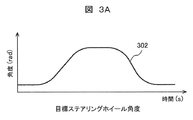
- FIG. 3A is a diagram showing a change in a target steering wheel angle and a time in a left turn operation according to the first embodiment of the present invention
- FIG. 3B is a change in an input steering wheel angle and a time in a left turn operation according to the first embodiment of the present invention.
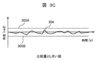
- FIG. 3C is a diagram showing a relationship between a comparison amount and a threshold value in the left turn operation according to the first embodiment of the present invention, and FIG.
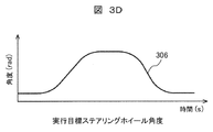
- 3D is an execution target steering wheel angle in the left turn operation according to the first embodiment of the present invention.
- FIG. 6 is a diagram showing changes in time and time. 3A to 3D, the horizontal axis indicates time (S), and the vertical axis indicates angle (rad).
- the host computer 2 In the left turn operation, the host computer 2 generates a trajectory to make a left turn and sets it as a target trajectory when it is determined from the road conditions and the driver's operation of the navigation device, the operation of the direction indicator, etc. (Step S201).
- the target steering wheel angle calculating means 33 calculates the target steering wheel angle 302 shown in FIG. 3A from the target trajectory (step of calculating the target steering wheel angle 302: S202).
- the steering wheel angle calculating means 32 calculates an input steering wheel angle 303 shown in FIG. 3B (calculates the input steering wheel angle 303). Step: S203).
- the comparing means 34 compares the target steering wheel angle 302 with the input steering wheel angle 303.
- the comparison means 34 calculates the difference between the target steering wheel angle 302 and the input steering wheel angle 303 shown in FIG. 3C, and uses this as a comparison amount 304 (calculates the difference between the target steering wheel angle 302 and the input steering wheel angle 303). (Step S204).
- the comparing means 34 determines whether or not the target trajectory needs to be corrected (step of determining whether or not the target trajectory can be corrected: S205). This is determined based on whether or not the comparison amount 304 falls within a range surrounded by the upper threshold 305A and the lower threshold 305B shown in FIG. 3C. In the present embodiment, as shown in FIG. 3C, since the comparison amount falls within a range surrounded by the upper threshold 305A and the lower threshold 305B, the comparison means 34 corrects the target trajectory. A judgment value that is not necessary is set, and the correction amount is also set to 0 (zero). In FIG. 3C, it is determined that there is no input as an operation intention of the driver 1, and correction of the target trajectory is not performed.
- the correction unit 35 corrects the target trajectory in response to the judgment value and the correction amount from the comparison unit 34.
- the correction unit 35 outputs the target trajectory as it is as the execution target trajectory (Step of outputting the execution target trajectory: S206).
- the calculation is not performed in the steer-by-wire system 3, but the execution target steering wheel angle 306 calculated based on the execution target trajectory is shown in FIG. 3D for explanation.
- the target steering wheel angle and the execution target steering wheel angle are equal.
- the tire steering angle calculating means 36 calculates the target tire steering angle from the execution target trajectory.
- the calculation here is, for example, to calculate a tire steering angle using a forward gaze model (step of calculating target tire steering angle: S208).
- the forward gaze model is a control method based on a gazing point, which is a point separated from the current position of the vehicle by a predetermined distance in the traveling direction of the vehicle.
- the steering device 37 outputs an operating force so that the actual tire steering angle matches the target tire steering angle, and controls the tire steering angle (Step of controlling the tire steering angle: S209).
- the tire steering angle operation of the vehicle is executed as described above.
- FIG. 4A shows an example of a change in lateral acceleration in a conventional steer-by-wire system.
- a change in the lateral acceleration 401 of the vehicle occurs according to the wobble, and the comfort of the person in the vehicle is improved. There is a risk of damage.
- the input steering wheel angle by the driver is compared with the target steering angle by the host computer. If the difference between the target steering wheel angle and the input steering wheel angle is small, the tire of the vehicle is calculated using the target steering wheel angle. Steer.
- the target steering wheel angle is calculated from the target trajectory planned by the host computer, and the target trajectory is naturally designed such that a change in lateral acceleration or the like is reduced. Therefore, in this embodiment, since the wheels are steered by the target trajectory, the vehicle can be driven in a state in which the change in the lateral acceleration is small without causing a wobble based on the driver's input.
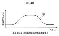
- FIG. 4B shows an example of a change in the lateral acceleration in the steer-by-wire system of this embodiment. In the present embodiment, even when the driver's input to the steering input device 31 fluctuates, it can be seen that the lateral acceleration 402 has no fine vibration and can be changed to a smooth state.
- the target trajectory is created by the host computer, and the target trajectory is corrected when the driver's operation intention is input to the target trajectory.
- the target trajectory is corrected when the driver's operation intention is input to the target trajectory.
- the steering angle of the tire is suppressed from fluctuating, and the tire steering operation with less disturbance of the behavior of the vehicle is realized. It is possible to realize a comfortable traveling for the person riding the vehicle.
- FIG. 5A is a diagram showing a change in a target steering wheel angle and a time in a left turn operation according to the first embodiment of the present invention
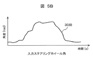
- FIG. 5B is a change in an input steering wheel angle and a time in a left turn operation according to the first embodiment of the present invention
- FIG. 5C is a diagram showing a relationship between a comparison amount and a threshold value in a left turn operation according to the first embodiment of the present invention
- FIG. 5D is an execution target steering wheel angle in a left turn operation according to the first embodiment of the present invention.
- FIG. 6 is a diagram showing changes in time and time. 5A to 5D, the horizontal axis represents time (S), and the vertical axis represents angle (rad).
- the host computer 2 In the left turn operation, the host computer 2 generates a trajectory to make a left turn and sets it as a target trajectory when it is determined from the road conditions and the driver's operation of the navigation device, the operation of the direction indicator, etc. (Step S201). In this process, the generation of the target trajectory and the generation of the target steering wheel angle 302 are executed in the same manner as when the target trajectory is not corrected (step of generating the target trajectory: S201).
- the target steering wheel angle calculating means 33 calculates the target steering wheel angle 302 shown in FIG. 5A from the target trajectory (step for calculating the target steering wheel angle 302: S202).
- the steering wheel angle calculation means 32 calculates an input steering wheel angle 303B shown in FIG. 5B based on a signal from the steering input device 31 (calculates the input steering wheel angle 303B). Step: S203).
- the driver 1 wants to travel further inside the target trajectory, and is in a state where a steering angle larger than the steering angle corresponding to the target trajectory is input to the steering input device 31.
- the comparison means 34 compares the target steering wheel angle 302 with the input steering wheel angle 303B.
- the comparison means 34 calculates the difference between the target steering wheel angle 302 and the input steering wheel angle 303B shown in FIG. 5C and uses the difference as a comparison amount 304B (calculates the difference between the target steering wheel angle 302 and the input steering wheel angle 303B). (Step S204).
- the comparing means 34 determines whether or not the target trajectory needs to be corrected (step of determining whether or not the target trajectory can be corrected: S205). This is determined based on whether or not the comparison amount 304B falls within a range surrounded by the upper threshold 305A and the lower threshold 305B shown in FIG. 5C. In FIG. 5C, the comparison amount deviates from the range surrounded by the upper and lower determination thresholds 305A and 305B at the deviation point 501. Therefore, the comparison means 34 sets a determination value that the target trajectory needs to be corrected at the deviating point 501, and calculates the correction amount. In FIG. 5C, it is determined that an input as an operation intention of the driver 1 has been made, and the target trajectory is corrected.
- the correction means 35 corrects the target trajectory in response to the judgment value and the correction amount from the comparison means.
- the correcting unit 35 corrects the target trajectory at the deviating point 501 and sets the corrected target trajectory as an execution target trajectory (Step S207: correcting the target trajectory and setting it as the execution target trajectory).
- Step S207 correcting the target trajectory and setting it as the execution target trajectory.
- the execution target steering wheel angle 306 calculated based on the corrected target trajectory for explanation and the execution target steering wheel calculated based on the uncorrected target trajectory are described.
- Angle 302 is shown in FIG. 5D.
- the execution target steering wheel angle 306 calculated based on the corrected target trajectory has a larger value than the deviation point 501 so as to correspond to a large steering angle input by the driver.
- the tire steering angle calculation means 36 calculates the target tire steering angle from the execution target trajectory (step of calculating the target tire steering angle: S208).
- the steering device 37 outputs an operating force so that the actual tire steering angle matches the target tire steering angle, and controls the tire steering angle (Step of controlling the tire steering angle: S209).
- the tire steering angle operation of the vehicle is executed as described above.
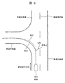
- FIG. 6 is a diagram illustrating a traveling locus of the vehicle when the target trajectory according to the first embodiment of the present invention is corrected.
- the vehicle 601 is traveling in the left lane within the outer lane. It is determined that the vehicle turns left based on the road condition, the operation of the navigation device by the driver, the operation of the direction indicator, and the like, and the target trajectory 602 is generated.
- the driver 1 wants to travel further inside the target trajectory 602
- a steering angle larger than the steering angle corresponding to the target trajectory 602 is input to the steering input device 31
- the above-described processing causes The target tire steering angle is calculated so that the corrected travel locus 603 is obtained.
- the traveling locus of the vehicle 601 becomes the target locus 602 when the target locus is not corrected, but becomes the running locus 603 when the target locus is corrected. This results in running inside.
- the target trajectory is created by the host computer, and the target trajectory is corrected when the driver's operation intention is input to the target trajectory. Even if the driver's operation is not intended, for example, when the driver's input fluctuates, the tire steering angle is prevented from fluctuating, and the running position of the vehicle is changed according to the driver's input. In addition, it is possible to realize a tire steering operation with less disturbance of the behavior of the vehicle, and to realize a steering that makes a person riding the vehicle comfortable.
- the target trajectory is created by the host computer, and the target trajectory is corrected when the driver's operation intention is input to the target trajectory. Even if the driver's input is not the driver's operation intention, for example, the driver's input fluctuates, the steering angle of the tire is suppressed from fluctuating, the vehicle's behavior is less disturbed, and the tire steering angle operation is reduced. It is possible to realize a comfortable running for the person who is doing.
- the driver's steering intention is obtained by comparing the vehicle state quantity when the vehicle travels on the target track with the vehicle state quantity calculated from the driver's input.
- the steering wheel angle was used as the vehicle state quantity when the vehicle travels on the target track and the vehicle state quantity calculated from the driver's input.
- the present invention is not limited to this.
- any one of the track, the stroke position of the steering device, the tire steering angle, the lateral acceleration, the longitudinal acceleration, the yaw rate, and the like may be used. Further, these may be appropriately combined.
- the target trajectory is corrected so as to respond to the driver's input.
- the present invention is not limited to this.
- a method of correcting a target value for example, a steering wheel angle, a tire steering angle, a lateral acceleration, a yaw rate, or the like may be used.
- the comparison means is used, and a predetermined threshold value is used in determining whether the correction of the target trajectory due to the steering intention from the driver's input is necessary, but the present invention is not limited to this. Instead, for example, the threshold value may be changed depending on the driving condition, road condition, surrounding condition, driver condition, driver skill, driver selection, value of danger degree in driving, etc. Good. An example is shown in FIG.
- FIG. 7 is a diagram showing the relationship between the comparison amount and the threshold value in a state where the threshold value is changed according to the first embodiment of the present invention.
- the threshold value is changed in the initial stage, the middle stage, and the final stage over time.
- the threshold value is set smaller at the beginning and end of the turning operation, and the threshold value is set larger at the middle period (the threshold value at the middle period is larger than the threshold value at the initial and end periods). Is also big.).
- the driver's anxiety of the driver can be eliminated and a comfortable steering can be realized by taking the driver's intention to start turning and adjusting the vehicle position with good response.
- As the threshold value to be changed a value of a danger degree in a turning situation, a road situation, a surrounding situation, a driver's state, a driver's skill, a driver's selection, or traveling may be used.
- the necessity of correcting the target trajectory is determined based on whether or not the threshold is exceeded.However, the present invention is not limited to this.
- the comparison result (driver's intention of steering), for example, by giving a nonlinear characteristic to the calculation of the correction amount, giving a small gain near the target value, and increasing the gain when it is far from the target value.
- the amount of correction of the target trajectory may be adjusted according to the magnitude of.
- the input to the steering input device by the driver is used as it is, and the input steering wheel angle is calculated.
- the present invention is not limited to this.
- the input to the steering input device is performed by the driver.
- the input change rate is calculated, and when the change rate is equal to or higher than a predetermined first cut level, the input steer wheel angle is calculated by converting the value so as to suppress the value equal to or higher than the first cut level.
- the steering control device 10 calculates the rate of change of the input of the driver 1 to the steering input device 31 and, when the rate of change is equal to or higher than the predetermined first cut level, sets the value equal to or higher than the first cut level. Suppress and use as input of driver 1.
- the steering control device 10 may estimate a section in which the steering wheel is to be switched by using a feature such as a discontinuous point of the steering operation in the past traveling data. The estimation may be performed based on the detection result. As a result, it is possible to suppress a wobble at the time of switching the steering wheel, which is a major cause of a change in the behavior of the vehicle, and to realize comfortable steering.
- the target trajectory is corrected in the steer-by-wire system.
- the target trajectory is corrected by the host computer.
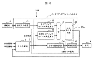
- FIG. 8 is a configuration diagram of a steering device according to a second embodiment of the present invention.
- the same components as those in the first embodiment are denoted by the same reference numerals, and detailed description thereof will be omitted.
- the steering control device 10A is configured by the host computer 2 and the steer-by-wire system 3.
- the trajectory recalculation judging means 38 is arranged after the comparing means 34.
- the steering wheel angle calculation means 32, the target steering wheel angle calculation means 33, the comparison means 34, the correction means 35, the tire steering angle calculation means 36, and the trajectory recalculation determination means 38 It constitutes the rudder control unit 30A.
- the trajectory recalculation determining means 38 outputs a request for the target trajectory recalculation to the host computer 2. Upon receiving this request, the host computer 2 recalculates the target trajectory based on the calculation result of the comparison means 34.
- the target trajectory is recalculated by the host computer based on the calculation result of the comparison means, so that even if the driver's input fluctuates, the steering angle of the tire fluctuates.
- the tire steering angle operation with less disturbance of the behavior of the vehicle can be realized, and the running of the vehicle can be made more comfortable.
- FIG. 9 is a configuration diagram of a steering device according to a third embodiment of the present invention. Components common to the first and second embodiments are denoted by the same reference numerals, and detailed description thereof will be omitted.
- the steering controller 10B is configured by the host computer 2 and the steer-by-wire system 3.
- the trajectory recalculation / correction determination means 39 is arranged at the subsequent stage of the comparison means.
- the steering wheel angle calculation means 32, the target steering wheel angle calculation means 33, the comparison means 34, the correction means 35, the tire steering angle calculation means 36, and the trajectory recalculation / correction determination means 39 The steering control unit 30B.
- the trajectory recalculation / correction determination means 39 determines the need for correction of the target trajectory and correction by recalculation of the target trajectory based on the calculation result of the comparison means 34.
- the judgment value indicating the correction of the target trajectory and the correction amount are output to the correction means 35.
- a request for target trajectory recalculation is output to the host computer 2.
- FIG. 10 is a diagram illustrating an example in which the correction of the target trajectory by the steer-by-wire system and the correction of the target trajectory by the host computer are combined.
- the vehicle 601 is traveling on the left side of a two-lane road.
- a track 1001 for changing the traveling position w0 in the same lane or a track 1002 for changing the lane to the right lane may be considered. That is, there are two (plural) target trajectories.
- the steer-by-wire system presumes that the traveling position changes in the same lane, and performs steering by correcting the target trajectory in the steer-by-wire system.
- the input steering wheel angle becomes larger in the middle.
- a position where the difference exceeds a predetermined value (threshold) and the difference becomes clear is determined as a judgment point 1003 (judgment area) of the target trajectory recalculation, and is input to the steering input device 31 by the driver at the judgment point 1003. Based on this, it is determined whether to change the traveling position in the same lane or to change to the right lane. If it is determined that the lane has been changed to the right lane, a request to recalculate the target trajectory is output to the host computer 2, and thereafter, steering is performed using the target trajectory for changing the lane to the right lane.
- the trajectory before correction and the trajectory after correction are connected by a higher-order (third or higher) curve, and the trajectory before correction and the trajectory after correction using the curve.
- the interpolation trajectory may be generated so as to transition to.
- FIG. 11 is a diagram illustrating an example in which a target trajectory is corrected when a plurality of target trajectories are estimated.
- the vehicle 601 is traveling on a one-lane road on each side.
- a trajectory 1101 that turns left or a trajectory 1102 that goes straight on may be considered. That is, there are two target trajectories.
- the steer-by-wire system sets the position at which the difference between the two trajectories becomes clear as the target trajectory selection determination point 1103, and based on the input from the driver at the determination point to the steering input device, turns left. It is determined whether to take a trajectory or a straight trajectory, and thereafter, the steering is performed using the selected target trajectory.
- the threshold value for determining that there is a steering intention may be reduced in order to reduce the driver's anxiety.
- the present embodiment it is possible to select an appropriate correction method according to the responsiveness of the correction of the target trajectory and the amount of the correction, and realize the steering that prevents the fluctuation that covers the response speed and the correction range in a wide range. can do.
- the present invention is not limited to the above-described embodiments, but includes various modifications.
- the above-described embodiments have been described in detail for easy understanding of the present invention, and are not necessarily limited to those having all the configurations described above.
- a part of the configuration of one embodiment can be replaced with the configuration of another embodiment, and the configuration of one embodiment can be added to the configuration of another embodiment.
- control lines and information lines are shown as necessary for the description, and do not necessarily indicate all control lines and information lines on a product. In fact, it can be considered that almost all components are connected to each other.
Landscapes
- Engineering & Computer Science (AREA)
- Chemical & Material Sciences (AREA)
- Combustion & Propulsion (AREA)
- Transportation (AREA)
- Mechanical Engineering (AREA)
- Steering Control In Accordance With Driving Conditions (AREA)
- Power Steering Mechanism (AREA)
Abstract
L'objectif de la présente invention est de fournir un dispositif de commande de virage pour un véhicule qui empêche un angle de braquage de pneu de fluctuer, même si une entrée provenant d'un conducteur fluctue, empêchant ainsi le comportement du véhicule d'être perturbé, et permettant un déplacement de telle sorte à assurer le confort d'une personne voyageant dans le véhicule. À cet effet, la présente invention est pourvue d'un dispositif d'entrée de direction (31) commandé par un conducteur (1), d'un dispositif de commande de direction (10) pour commander la rotation des roues en fonction d'une entrée provenant du conducteur (1), d'un dispositif de rotation (37) pour faire tourner les roues en fonction du dispositif de commande de direction (10), et d'un ordinateur de niveau supérieur (2) pour créer une trajectoire cible pour les roues. Le dispositif de commande de direction (10) détermine la rotation des roues en comparant la trajectoire cible avec l'entrée dans le dispositif d'entrée de direction (31) par le conducteur, et si une entrée qui est une opération prévue par le conducteur (1) est entrée dans le dispositif d'entrée de direction (31), corrige la rotation des roues en corrigeant la trajectoire cible sur la base de l'entrée provenant du conducteur (1).
Applications Claiming Priority (2)
| Application Number | Priority Date | Filing Date | Title |
|---|---|---|---|
| JP2018-138981 | 2018-07-25 | ||
| JP2018138981A JP7032262B2 (ja) | 2018-07-25 | 2018-07-25 | 車両の操舵制御装置 |
Publications (1)
| Publication Number | Publication Date |
|---|---|
| WO2020021817A1 true WO2020021817A1 (fr) | 2020-01-30 |
Family
ID=69182218
Family Applications (1)
| Application Number | Title | Priority Date | Filing Date |
|---|---|---|---|
| PCT/JP2019/019027 Ceased WO2020021817A1 (fr) | 2018-07-25 | 2019-05-14 | Dispositif de commande de direction pour véhicule |
Country Status (2)
| Country | Link |
|---|---|
| JP (1) | JP7032262B2 (fr) |
| WO (1) | WO2020021817A1 (fr) |
Cited By (2)
| Publication number | Priority date | Publication date | Assignee | Title |
|---|---|---|---|---|
| CN116198596A (zh) * | 2023-03-22 | 2023-06-02 | 中国第一汽车股份有限公司 | 线控转向车辆的弯道行驶控制方法、装置、设备及介质 |
| JP2024158236A (ja) * | 2023-04-27 | 2024-11-08 | トヨタ自動車株式会社 | 車両運転支援装置、車両運転支援方法及び車両運転支援プログラム |
Families Citing this family (1)
| Publication number | Priority date | Publication date | Assignee | Title |
|---|---|---|---|---|
| JP6937397B2 (ja) | 2020-01-31 | 2021-09-22 | セイコーインスツル株式会社 | 薬液ポンプ及び薬液投与装置 |
Citations (9)
| Publication number | Priority date | Publication date | Assignee | Title |
|---|---|---|---|---|
| JP2000153769A (ja) * | 1998-11-19 | 2000-06-06 | Nissan Motor Co Ltd | 車両の自動操舵装置 |
| JP2009208682A (ja) * | 2008-03-05 | 2009-09-17 | Nissan Motor Co Ltd | 車両用走行制御装置及びその方法 |
| JP2010188825A (ja) * | 2009-02-17 | 2010-09-02 | Denso Corp | 操舵負荷推定装置及び電動パワーステアリング装置 |
| WO2010109676A1 (fr) * | 2009-03-25 | 2010-09-30 | トヨタ自動車株式会社 | Appareil de direction pour véhicule |
| WO2012014399A1 (fr) * | 2010-07-27 | 2012-02-02 | 三菱電機株式会社 | Dispositif de direction assistée électrique |
| JP2013129328A (ja) * | 2011-12-21 | 2013-07-04 | Toyota Motor Corp | 軌跡制御装置および軌跡制御方法 |
| JP2015151048A (ja) * | 2014-02-17 | 2015-08-24 | トヨタ自動車株式会社 | 車両用軌跡制御装置 |
| US20150353085A1 (en) * | 2014-06-05 | 2015-12-10 | GM Global Technology Operations LLC | Lane change path planning algorithm for autonomous driving vehicle |
| JP2018177181A (ja) * | 2017-04-12 | 2018-11-15 | トヨタ自動車株式会社 | 車線変更支援装置 |
-
2018
- 2018-07-25 JP JP2018138981A patent/JP7032262B2/ja not_active Expired - Fee Related
-
2019
- 2019-05-14 WO PCT/JP2019/019027 patent/WO2020021817A1/fr not_active Ceased
Patent Citations (9)
| Publication number | Priority date | Publication date | Assignee | Title |
|---|---|---|---|---|
| JP2000153769A (ja) * | 1998-11-19 | 2000-06-06 | Nissan Motor Co Ltd | 車両の自動操舵装置 |
| JP2009208682A (ja) * | 2008-03-05 | 2009-09-17 | Nissan Motor Co Ltd | 車両用走行制御装置及びその方法 |
| JP2010188825A (ja) * | 2009-02-17 | 2010-09-02 | Denso Corp | 操舵負荷推定装置及び電動パワーステアリング装置 |
| WO2010109676A1 (fr) * | 2009-03-25 | 2010-09-30 | トヨタ自動車株式会社 | Appareil de direction pour véhicule |
| WO2012014399A1 (fr) * | 2010-07-27 | 2012-02-02 | 三菱電機株式会社 | Dispositif de direction assistée électrique |
| JP2013129328A (ja) * | 2011-12-21 | 2013-07-04 | Toyota Motor Corp | 軌跡制御装置および軌跡制御方法 |
| JP2015151048A (ja) * | 2014-02-17 | 2015-08-24 | トヨタ自動車株式会社 | 車両用軌跡制御装置 |
| US20150353085A1 (en) * | 2014-06-05 | 2015-12-10 | GM Global Technology Operations LLC | Lane change path planning algorithm for autonomous driving vehicle |
| JP2018177181A (ja) * | 2017-04-12 | 2018-11-15 | トヨタ自動車株式会社 | 車線変更支援装置 |
Cited By (3)
| Publication number | Priority date | Publication date | Assignee | Title |
|---|---|---|---|---|
| CN116198596A (zh) * | 2023-03-22 | 2023-06-02 | 中国第一汽车股份有限公司 | 线控转向车辆的弯道行驶控制方法、装置、设备及介质 |
| JP2024158236A (ja) * | 2023-04-27 | 2024-11-08 | トヨタ自動車株式会社 | 車両運転支援装置、車両運転支援方法及び車両運転支援プログラム |
| JP7816272B2 (ja) | 2023-04-27 | 2026-02-18 | トヨタ自動車株式会社 | 車両運転支援装置、車両運転支援方法及び車両運転支援プログラム |
Also Published As
| Publication number | Publication date |
|---|---|
| JP7032262B2 (ja) | 2022-03-08 |
| JP2020015399A (ja) | 2020-01-30 |
Similar Documents
| Publication | Publication Date | Title |
|---|---|---|
| US10336366B2 (en) | Driving support apparatus for vehicle | |
| JP6078124B1 (ja) | 車両の制御装置及び車両の制御方法 | |
| JP3539362B2 (ja) | 車線追従走行制御装置 | |
| CN105980238B (zh) | 车辆转向控制装置 | |
| US9896122B2 (en) | Steering control device, and steering control method | |
| CN111433110A (zh) | 车辆的转向控制方法及车辆的转向控制装置 | |
| CN106985906A (zh) | 车辆用驾驶辅助装置 | |
| CN104918843A (zh) | 车道内行驶辅助装置 | |
| JP2023504431A (ja) | モータ車両を制御するための方法 | |
| WO2006101005A1 (fr) | Dispositif de commande de direction pour vehicules | |
| JP6419671B2 (ja) | 車両用操舵装置および車両用操舵方法 | |
| JP2018177120A (ja) | 自動運転システム | |
| JP2019214304A (ja) | 車両制御装置、車両制御方法、及び車両制御システム | |
| US12168484B2 (en) | Railborne driver assistance device and method for supporting or automating the lateral control of a vehicle | |
| WO2020021817A1 (fr) | Dispositif de commande de direction pour véhicule | |
| JP2018047827A (ja) | 操舵制御装置 | |
| CN112512900B (zh) | 转向控制装置 | |
| JP6012824B1 (ja) | 車両用操舵装置および車両操舵制御方法 | |
| JP6098545B2 (ja) | 車両制御装置 | |
| KR102347661B1 (ko) | 차량의 언더스티어 및 오버스티어 보상 제어 방법 | |
| WO2023157337A1 (fr) | Dispositif de commande de véhicule | |
| CN115571218B (zh) | 一种转向力矩补偿方法、装置及车辆 | |
| JP2010155561A (ja) | 車両制御装置及び車両制御方法 | |
| CN112449624B (zh) | 操舵控制装置以及操舵控制方法 | |
| JP2017065486A (ja) | 車両の制御装置 |
Legal Events
| Date | Code | Title | Description |
|---|---|---|---|
| 121 | Ep: the epo has been informed by wipo that ep was designated in this application |
Ref document number: 19841302 Country of ref document: EP Kind code of ref document: A1 |
|
| NENP | Non-entry into the national phase |
Ref country code: DE |
|
| 122 | Ep: pct application non-entry in european phase |
Ref document number: 19841302 Country of ref document: EP Kind code of ref document: A1 |