WO2020021817A1 - 車両の操舵制御装置 - Google Patents
車両の操舵制御装置 Download PDFInfo
- Publication number
- WO2020021817A1 WO2020021817A1 PCT/JP2019/019027 JP2019019027W WO2020021817A1 WO 2020021817 A1 WO2020021817 A1 WO 2020021817A1 JP 2019019027 W JP2019019027 W JP 2019019027W WO 2020021817 A1 WO2020021817 A1 WO 2020021817A1
- Authority
- WO
- WIPO (PCT)
- Prior art keywords
- steering
- driver
- vehicle
- input
- control device
- Prior art date
- Legal status (The legal status is an assumption and is not a legal conclusion. Google has not performed a legal analysis and makes no representation as to the accuracy of the status listed.)
- Ceased
Links
Images










Classifications
-
- B—PERFORMING OPERATIONS; TRANSPORTING
- B62—LAND VEHICLES FOR TRAVELLING OTHERWISE THAN ON RAILS
- B62D—MOTOR VEHICLES; TRAILERS
- B62D5/00—Power-assisted or power-driven steering
- B62D5/04—Power-assisted or power-driven steering electrical, e.g. using an electric servo-motor connected to, or forming part of, the steering gear
-
- B—PERFORMING OPERATIONS; TRANSPORTING
- B62—LAND VEHICLES FOR TRAVELLING OTHERWISE THAN ON RAILS
- B62D—MOTOR VEHICLES; TRAILERS
- B62D6/00—Arrangements for automatically controlling steering depending on driving conditions sensed and responded to, e.g. control circuits
Definitions
- the present invention relates to a vehicle steering control device.
- Patent Document 1 discloses an example of a vehicle steering apparatus using a steer-by-wire system.
- Patent Document 1 states that “a target turning angle calculation unit calculates a target turning angle ⁇ * based on a steering angle ⁇ and a vehicle speed V.
- a correction turning angle calculation unit is determined based on specifications of a vehicle. Then, a difference between a transfer function G (s) as a first transfer function having a steering angle ⁇ as an input and a yaw rate ⁇ of the vehicle as an output and a steady component G (0) of the transfer function G (s) is used.
- the corrected turning angle calculation unit calculates the corrected turning angle ⁇ c by multiplying the transfer function K (s) by the target turning speed ⁇ * '.
- Patent Document 1 discloses a technique in which a correction based on a transfer function of a steering system is performed to improve a response of a tire steering angle to a driver's input.
- Patent Literature 1 provides a steering system that operates according to an input by a driver's steering operation.
- the tire steering angle is reduced. The result is that the behavior of the vehicle fluctuates, and the behavior of the vehicle is disturbed, which causes discomfort to the occupant of the vehicle.
- the object of the present invention is to solve the above problems, even when the input of the driver fluctuates, it is possible to suppress the fluctuation of the steering angle of the tire, to achieve a tire steering angle operation with less disturbance to the behavior of the vehicle,
- An object of the present invention is to provide a vehicle steering control device that makes a person riding a vehicle comfortable.
- the present invention is characterized in that a steering input device operated by a driver, a steering control unit that controls steering of wheels according to an input of the driver,
- a steering control device for a vehicle comprising: a steering device that performs steering of the wheel according to a control unit; a target trajectory creating unit that creates a target trajectory of the wheel; and the steering control unit includes: Comparing the target trajectory and the input of the driver to the steering input device to determine the turning of the wheels, and when there is an input as the driver's operation intention to the steering input device,
- the target trajectory is corrected based on the driver's input to correct the steering of the wheel.
- the steering angle of the tire can be suppressed from fluctuating, and the behavior of the vehicle can be controlled with less disturbance and the steering angle of the tire can be reduced. It is possible to provide a vehicle steering control device that makes a person comfortable.
- FIG. 1 is an example of a configuration diagram of a steering device according to a first embodiment of the present invention. It is an example of the flowchart which shows the process of the steering of the wheel in the left turn operation
- FIG. 6 is a diagram illustrating a change in a target steering wheel angle and time in a left turn operation according to the first example of the present invention.
- FIG. 4 is a diagram illustrating changes in input steering wheel angle and time in a left turn operation according to the first embodiment of the present invention.
- FIG. 7 is a diagram illustrating a relationship between a comparison amount and a threshold value in a left turn operation according to the first example of the present invention.
- FIG. 6 is a diagram showing a change in an execution target steering wheel angle and time in a left turn operation according to the first embodiment of the present invention.
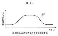
- FIG. 10 is a diagram illustrating an example of a change in lateral acceleration in a conventional steer-by-wire system. It is a figure showing an example of change of lateral acceleration in a steer-by-wire system of this example.
- FIG. 6 is a diagram illustrating a change in a target steering wheel angle and time in a left turn operation according to the first example of the present invention.
- FIG. 4 is a diagram illustrating changes in input steering wheel angle and time in a left turn operation according to the first embodiment of the present invention.
- FIG. 7 is a diagram illustrating a relationship between a comparison amount and a threshold value in a left turn operation according to the first example of the present invention.
- FIG. 6 is a diagram showing a change in an execution target steering wheel angle and time in a left turn operation according to the first embodiment of the present invention.
- FIG. 4 is a diagram illustrating a traveling locus of a vehicle when a target trajectory according to the first embodiment of the present invention is corrected.
- FIG. 7 is a diagram illustrating a relationship between a comparison amount and a threshold value in a state where the threshold value is changed according to the first example of the present invention.
- FIG. 6 is a configuration diagram of a steering device according to a second embodiment of the present invention.
- FIG. 9 is a configuration diagram of a steering device according to a third embodiment of the present invention. It is a figure which shows the example which combined correction
- FIG. 11 is a diagram illustrating an example in which a target trajectory is corrected when a plurality of target trajectories are estimated.
- the steering device of the present embodiment uses a steering wheel as a driver's steering input device, and uses a steer-by-wire system as a means for performing steering of a tire of a front wheel of a vehicle.
- FIG. 1 is an example of a configuration diagram of a steering device according to a first embodiment of the present invention.
- a target trajectory (hereinafter, simply referred to as a target trajectory) is calculated by the host computer 2.
- the host computer for example, an electronic control unit (ECU) is used.
- the steering wheel angle is used as the vehicle state quantity for comparing the input of the driver 1 with the target track.
- the steering control device 10 is configured by the host computer 2 and the steer-by-wire system 3.
- FIG. 1 also illustrates the driver 1 and the vehicle 4 so that the relationship between the steering control device 10 and the driver 1 and the vehicle 4 is clear.
- the driver 1 determines an appropriate steering angle of the steering wheel for operating the vehicle based on the vehicle and surrounding conditions, and operates the steering input device 31.
- the movement of the steering input device 31 is detected by a sensor, and is converted into an input steering wheel angle by a steering wheel angle calculation means 32.
- the host computer 2 is a computer that can perform automatic driving, advanced driver support, and the like, and calculates a target trajectory from vehicle information such as a road map, external information from a camera or the like, and a vehicle position using a GPS sensor.
- the host computer 2 of the present embodiment functions as a target trajectory creating means for creating a target trajectory of the vehicle.
- the target trajectory is input to the steer-by-wire system, and two types of processing are performed.
- the target steering wheel angle calculation means 33 is first converted by the target steering wheel angle calculation means 33 into a target steering wheel angle which is a value to be taken for the vehicle to travel on the target track. Thereafter, the comparison means 34 compares the input steering wheel angle with the input steering wheel angle, and converts the correction value into a judgment value indicating whether the target trajectory needs to be corrected and the correction amount.
- the other is input to the correction means 35, where the correction is made based on the result of the comparison means 34.
- the corrected target trajectory is passed to the tire steering angle calculating means 36 as an execution target trajectory, and is converted into a target tire steering angle.
- the target tire steering angle is input to the steering device 37, converted into an operating force for actually steering the tire, and output from the steer-by-wire system 3.
- the vehicle 4 receives the operation force and turns the tire. As a result, the running state of the vehicle 4 changes.
- the steering control unit 30 is configured by the steering wheel angle calculation unit 32, the target steering wheel angle calculation unit 33, the comparison unit 34, the correction unit 35, and the tire steering angle calculation unit 36. I have.
- the turning control unit 30 controls the turning of the wheels according to the input of the driver 1.
- FIG. 2 is an example of a flowchart showing a process of turning a wheel in a left turn operation according to the first embodiment of the present invention.
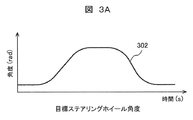
- FIG. 3A is a diagram showing a change in a target steering wheel angle and a time in a left turn operation according to the first embodiment of the present invention
- FIG. 3B is a change in an input steering wheel angle and a time in a left turn operation according to the first embodiment of the present invention.
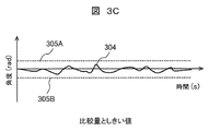
- FIG. 3C is a diagram showing a relationship between a comparison amount and a threshold value in the left turn operation according to the first embodiment of the present invention, and FIG.
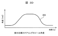
- 3D is an execution target steering wheel angle in the left turn operation according to the first embodiment of the present invention.
- FIG. 6 is a diagram showing changes in time and time. 3A to 3D, the horizontal axis indicates time (S), and the vertical axis indicates angle (rad).
- the host computer 2 In the left turn operation, the host computer 2 generates a trajectory to make a left turn and sets it as a target trajectory when it is determined from the road conditions and the driver's operation of the navigation device, the operation of the direction indicator, etc. (Step S201).
- the target steering wheel angle calculating means 33 calculates the target steering wheel angle 302 shown in FIG. 3A from the target trajectory (step of calculating the target steering wheel angle 302: S202).
- the steering wheel angle calculating means 32 calculates an input steering wheel angle 303 shown in FIG. 3B (calculates the input steering wheel angle 303). Step: S203).
- the comparing means 34 compares the target steering wheel angle 302 with the input steering wheel angle 303.
- the comparison means 34 calculates the difference between the target steering wheel angle 302 and the input steering wheel angle 303 shown in FIG. 3C, and uses this as a comparison amount 304 (calculates the difference between the target steering wheel angle 302 and the input steering wheel angle 303). (Step S204).
- the comparing means 34 determines whether or not the target trajectory needs to be corrected (step of determining whether or not the target trajectory can be corrected: S205). This is determined based on whether or not the comparison amount 304 falls within a range surrounded by the upper threshold 305A and the lower threshold 305B shown in FIG. 3C. In the present embodiment, as shown in FIG. 3C, since the comparison amount falls within a range surrounded by the upper threshold 305A and the lower threshold 305B, the comparison means 34 corrects the target trajectory. A judgment value that is not necessary is set, and the correction amount is also set to 0 (zero). In FIG. 3C, it is determined that there is no input as an operation intention of the driver 1, and correction of the target trajectory is not performed.
- the correction unit 35 corrects the target trajectory in response to the judgment value and the correction amount from the comparison unit 34.
- the correction unit 35 outputs the target trajectory as it is as the execution target trajectory (Step of outputting the execution target trajectory: S206).
- the calculation is not performed in the steer-by-wire system 3, but the execution target steering wheel angle 306 calculated based on the execution target trajectory is shown in FIG. 3D for explanation.
- the target steering wheel angle and the execution target steering wheel angle are equal.
- the tire steering angle calculating means 36 calculates the target tire steering angle from the execution target trajectory.
- the calculation here is, for example, to calculate a tire steering angle using a forward gaze model (step of calculating target tire steering angle: S208).
- the forward gaze model is a control method based on a gazing point, which is a point separated from the current position of the vehicle by a predetermined distance in the traveling direction of the vehicle.
- the steering device 37 outputs an operating force so that the actual tire steering angle matches the target tire steering angle, and controls the tire steering angle (Step of controlling the tire steering angle: S209).
- the tire steering angle operation of the vehicle is executed as described above.
- FIG. 4A shows an example of a change in lateral acceleration in a conventional steer-by-wire system.
- a change in the lateral acceleration 401 of the vehicle occurs according to the wobble, and the comfort of the person in the vehicle is improved. There is a risk of damage.
- the input steering wheel angle by the driver is compared with the target steering angle by the host computer. If the difference between the target steering wheel angle and the input steering wheel angle is small, the tire of the vehicle is calculated using the target steering wheel angle. Steer.
- the target steering wheel angle is calculated from the target trajectory planned by the host computer, and the target trajectory is naturally designed such that a change in lateral acceleration or the like is reduced. Therefore, in this embodiment, since the wheels are steered by the target trajectory, the vehicle can be driven in a state in which the change in the lateral acceleration is small without causing a wobble based on the driver's input.
- FIG. 4B shows an example of a change in the lateral acceleration in the steer-by-wire system of this embodiment. In the present embodiment, even when the driver's input to the steering input device 31 fluctuates, it can be seen that the lateral acceleration 402 has no fine vibration and can be changed to a smooth state.
- the target trajectory is created by the host computer, and the target trajectory is corrected when the driver's operation intention is input to the target trajectory.
- the target trajectory is corrected when the driver's operation intention is input to the target trajectory.
- the steering angle of the tire is suppressed from fluctuating, and the tire steering operation with less disturbance of the behavior of the vehicle is realized. It is possible to realize a comfortable traveling for the person riding the vehicle.
- FIG. 5A is a diagram showing a change in a target steering wheel angle and a time in a left turn operation according to the first embodiment of the present invention
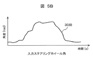
- FIG. 5B is a change in an input steering wheel angle and a time in a left turn operation according to the first embodiment of the present invention
- FIG. 5C is a diagram showing a relationship between a comparison amount and a threshold value in a left turn operation according to the first embodiment of the present invention
- FIG. 5D is an execution target steering wheel angle in a left turn operation according to the first embodiment of the present invention.
- FIG. 6 is a diagram showing changes in time and time. 5A to 5D, the horizontal axis represents time (S), and the vertical axis represents angle (rad).
- the host computer 2 In the left turn operation, the host computer 2 generates a trajectory to make a left turn and sets it as a target trajectory when it is determined from the road conditions and the driver's operation of the navigation device, the operation of the direction indicator, etc. (Step S201). In this process, the generation of the target trajectory and the generation of the target steering wheel angle 302 are executed in the same manner as when the target trajectory is not corrected (step of generating the target trajectory: S201).
- the target steering wheel angle calculating means 33 calculates the target steering wheel angle 302 shown in FIG. 5A from the target trajectory (step for calculating the target steering wheel angle 302: S202).
- the steering wheel angle calculation means 32 calculates an input steering wheel angle 303B shown in FIG. 5B based on a signal from the steering input device 31 (calculates the input steering wheel angle 303B). Step: S203).
- the driver 1 wants to travel further inside the target trajectory, and is in a state where a steering angle larger than the steering angle corresponding to the target trajectory is input to the steering input device 31.
- the comparison means 34 compares the target steering wheel angle 302 with the input steering wheel angle 303B.
- the comparison means 34 calculates the difference between the target steering wheel angle 302 and the input steering wheel angle 303B shown in FIG. 5C and uses the difference as a comparison amount 304B (calculates the difference between the target steering wheel angle 302 and the input steering wheel angle 303B). (Step S204).
- the comparing means 34 determines whether or not the target trajectory needs to be corrected (step of determining whether or not the target trajectory can be corrected: S205). This is determined based on whether or not the comparison amount 304B falls within a range surrounded by the upper threshold 305A and the lower threshold 305B shown in FIG. 5C. In FIG. 5C, the comparison amount deviates from the range surrounded by the upper and lower determination thresholds 305A and 305B at the deviation point 501. Therefore, the comparison means 34 sets a determination value that the target trajectory needs to be corrected at the deviating point 501, and calculates the correction amount. In FIG. 5C, it is determined that an input as an operation intention of the driver 1 has been made, and the target trajectory is corrected.
- the correction means 35 corrects the target trajectory in response to the judgment value and the correction amount from the comparison means.
- the correcting unit 35 corrects the target trajectory at the deviating point 501 and sets the corrected target trajectory as an execution target trajectory (Step S207: correcting the target trajectory and setting it as the execution target trajectory).
- Step S207 correcting the target trajectory and setting it as the execution target trajectory.
- the execution target steering wheel angle 306 calculated based on the corrected target trajectory for explanation and the execution target steering wheel calculated based on the uncorrected target trajectory are described.
- Angle 302 is shown in FIG. 5D.
- the execution target steering wheel angle 306 calculated based on the corrected target trajectory has a larger value than the deviation point 501 so as to correspond to a large steering angle input by the driver.
- the tire steering angle calculation means 36 calculates the target tire steering angle from the execution target trajectory (step of calculating the target tire steering angle: S208).
- the steering device 37 outputs an operating force so that the actual tire steering angle matches the target tire steering angle, and controls the tire steering angle (Step of controlling the tire steering angle: S209).
- the tire steering angle operation of the vehicle is executed as described above.
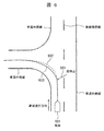
- FIG. 6 is a diagram illustrating a traveling locus of the vehicle when the target trajectory according to the first embodiment of the present invention is corrected.
- the vehicle 601 is traveling in the left lane within the outer lane. It is determined that the vehicle turns left based on the road condition, the operation of the navigation device by the driver, the operation of the direction indicator, and the like, and the target trajectory 602 is generated.
- the driver 1 wants to travel further inside the target trajectory 602
- a steering angle larger than the steering angle corresponding to the target trajectory 602 is input to the steering input device 31
- the above-described processing causes The target tire steering angle is calculated so that the corrected travel locus 603 is obtained.
- the traveling locus of the vehicle 601 becomes the target locus 602 when the target locus is not corrected, but becomes the running locus 603 when the target locus is corrected. This results in running inside.
- the target trajectory is created by the host computer, and the target trajectory is corrected when the driver's operation intention is input to the target trajectory. Even if the driver's operation is not intended, for example, when the driver's input fluctuates, the tire steering angle is prevented from fluctuating, and the running position of the vehicle is changed according to the driver's input. In addition, it is possible to realize a tire steering operation with less disturbance of the behavior of the vehicle, and to realize a steering that makes a person riding the vehicle comfortable.
- the target trajectory is created by the host computer, and the target trajectory is corrected when the driver's operation intention is input to the target trajectory. Even if the driver's input is not the driver's operation intention, for example, the driver's input fluctuates, the steering angle of the tire is suppressed from fluctuating, the vehicle's behavior is less disturbed, and the tire steering angle operation is reduced. It is possible to realize a comfortable running for the person who is doing.
- the driver's steering intention is obtained by comparing the vehicle state quantity when the vehicle travels on the target track with the vehicle state quantity calculated from the driver's input.
- the steering wheel angle was used as the vehicle state quantity when the vehicle travels on the target track and the vehicle state quantity calculated from the driver's input.
- the present invention is not limited to this.
- any one of the track, the stroke position of the steering device, the tire steering angle, the lateral acceleration, the longitudinal acceleration, the yaw rate, and the like may be used. Further, these may be appropriately combined.
- the target trajectory is corrected so as to respond to the driver's input.
- the present invention is not limited to this.
- a method of correcting a target value for example, a steering wheel angle, a tire steering angle, a lateral acceleration, a yaw rate, or the like may be used.
- the comparison means is used, and a predetermined threshold value is used in determining whether the correction of the target trajectory due to the steering intention from the driver's input is necessary, but the present invention is not limited to this. Instead, for example, the threshold value may be changed depending on the driving condition, road condition, surrounding condition, driver condition, driver skill, driver selection, value of danger degree in driving, etc. Good. An example is shown in FIG.
- FIG. 7 is a diagram showing the relationship between the comparison amount and the threshold value in a state where the threshold value is changed according to the first embodiment of the present invention.
- the threshold value is changed in the initial stage, the middle stage, and the final stage over time.
- the threshold value is set smaller at the beginning and end of the turning operation, and the threshold value is set larger at the middle period (the threshold value at the middle period is larger than the threshold value at the initial and end periods). Is also big.).
- the driver's anxiety of the driver can be eliminated and a comfortable steering can be realized by taking the driver's intention to start turning and adjusting the vehicle position with good response.
- As the threshold value to be changed a value of a danger degree in a turning situation, a road situation, a surrounding situation, a driver's state, a driver's skill, a driver's selection, or traveling may be used.
- the necessity of correcting the target trajectory is determined based on whether or not the threshold is exceeded.However, the present invention is not limited to this.
- the comparison result (driver's intention of steering), for example, by giving a nonlinear characteristic to the calculation of the correction amount, giving a small gain near the target value, and increasing the gain when it is far from the target value.
- the amount of correction of the target trajectory may be adjusted according to the magnitude of.
- the input to the steering input device by the driver is used as it is, and the input steering wheel angle is calculated.
- the present invention is not limited to this.
- the input to the steering input device is performed by the driver.
- the input change rate is calculated, and when the change rate is equal to or higher than a predetermined first cut level, the input steer wheel angle is calculated by converting the value so as to suppress the value equal to or higher than the first cut level.
- the steering control device 10 calculates the rate of change of the input of the driver 1 to the steering input device 31 and, when the rate of change is equal to or higher than the predetermined first cut level, sets the value equal to or higher than the first cut level. Suppress and use as input of driver 1.
- the steering control device 10 may estimate a section in which the steering wheel is to be switched by using a feature such as a discontinuous point of the steering operation in the past traveling data. The estimation may be performed based on the detection result. As a result, it is possible to suppress a wobble at the time of switching the steering wheel, which is a major cause of a change in the behavior of the vehicle, and to realize comfortable steering.
- the target trajectory is corrected in the steer-by-wire system.
- the target trajectory is corrected by the host computer.
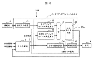
- FIG. 8 is a configuration diagram of a steering device according to a second embodiment of the present invention.
- the same components as those in the first embodiment are denoted by the same reference numerals, and detailed description thereof will be omitted.
- the steering control device 10A is configured by the host computer 2 and the steer-by-wire system 3.
- the trajectory recalculation judging means 38 is arranged after the comparing means 34.
- the steering wheel angle calculation means 32, the target steering wheel angle calculation means 33, the comparison means 34, the correction means 35, the tire steering angle calculation means 36, and the trajectory recalculation determination means 38 It constitutes the rudder control unit 30A.
- the trajectory recalculation determining means 38 outputs a request for the target trajectory recalculation to the host computer 2. Upon receiving this request, the host computer 2 recalculates the target trajectory based on the calculation result of the comparison means 34.
- the target trajectory is recalculated by the host computer based on the calculation result of the comparison means, so that even if the driver's input fluctuates, the steering angle of the tire fluctuates.
- the tire steering angle operation with less disturbance of the behavior of the vehicle can be realized, and the running of the vehicle can be made more comfortable.
- FIG. 9 is a configuration diagram of a steering device according to a third embodiment of the present invention. Components common to the first and second embodiments are denoted by the same reference numerals, and detailed description thereof will be omitted.
- the steering controller 10B is configured by the host computer 2 and the steer-by-wire system 3.
- the trajectory recalculation / correction determination means 39 is arranged at the subsequent stage of the comparison means.
- the steering wheel angle calculation means 32, the target steering wheel angle calculation means 33, the comparison means 34, the correction means 35, the tire steering angle calculation means 36, and the trajectory recalculation / correction determination means 39 The steering control unit 30B.
- the trajectory recalculation / correction determination means 39 determines the need for correction of the target trajectory and correction by recalculation of the target trajectory based on the calculation result of the comparison means 34.
- the judgment value indicating the correction of the target trajectory and the correction amount are output to the correction means 35.
- a request for target trajectory recalculation is output to the host computer 2.
- FIG. 10 is a diagram illustrating an example in which the correction of the target trajectory by the steer-by-wire system and the correction of the target trajectory by the host computer are combined.
- the vehicle 601 is traveling on the left side of a two-lane road.
- a track 1001 for changing the traveling position w0 in the same lane or a track 1002 for changing the lane to the right lane may be considered. That is, there are two (plural) target trajectories.
- the steer-by-wire system presumes that the traveling position changes in the same lane, and performs steering by correcting the target trajectory in the steer-by-wire system.
- the input steering wheel angle becomes larger in the middle.
- a position where the difference exceeds a predetermined value (threshold) and the difference becomes clear is determined as a judgment point 1003 (judgment area) of the target trajectory recalculation, and is input to the steering input device 31 by the driver at the judgment point 1003. Based on this, it is determined whether to change the traveling position in the same lane or to change to the right lane. If it is determined that the lane has been changed to the right lane, a request to recalculate the target trajectory is output to the host computer 2, and thereafter, steering is performed using the target trajectory for changing the lane to the right lane.
- the trajectory before correction and the trajectory after correction are connected by a higher-order (third or higher) curve, and the trajectory before correction and the trajectory after correction using the curve.
- the interpolation trajectory may be generated so as to transition to.
- FIG. 11 is a diagram illustrating an example in which a target trajectory is corrected when a plurality of target trajectories are estimated.
- the vehicle 601 is traveling on a one-lane road on each side.
- a trajectory 1101 that turns left or a trajectory 1102 that goes straight on may be considered. That is, there are two target trajectories.
- the steer-by-wire system sets the position at which the difference between the two trajectories becomes clear as the target trajectory selection determination point 1103, and based on the input from the driver at the determination point to the steering input device, turns left. It is determined whether to take a trajectory or a straight trajectory, and thereafter, the steering is performed using the selected target trajectory.
- the threshold value for determining that there is a steering intention may be reduced in order to reduce the driver's anxiety.
- the present embodiment it is possible to select an appropriate correction method according to the responsiveness of the correction of the target trajectory and the amount of the correction, and realize the steering that prevents the fluctuation that covers the response speed and the correction range in a wide range. can do.
- the present invention is not limited to the above-described embodiments, but includes various modifications.
- the above-described embodiments have been described in detail for easy understanding of the present invention, and are not necessarily limited to those having all the configurations described above.
- a part of the configuration of one embodiment can be replaced with the configuration of another embodiment, and the configuration of one embodiment can be added to the configuration of another embodiment.
- control lines and information lines are shown as necessary for the description, and do not necessarily indicate all control lines and information lines on a product. In fact, it can be considered that almost all components are connected to each other.
Landscapes
- Engineering & Computer Science (AREA)
- Chemical & Material Sciences (AREA)
- Combustion & Propulsion (AREA)
- Transportation (AREA)
- Mechanical Engineering (AREA)
- Steering Control In Accordance With Driving Conditions (AREA)
- Power Steering Mechanism (AREA)
Abstract
本発明の目的は、運転者の入力がふらついた場合であっても、タイヤの舵角がふらつくことを防止して、車両の挙動を乱さないようにし、車両に乗車している人が快適となるような走行ができる車両の転舵制御装置を提供することにある。そのために本発明は、運転者1が操作する操舵入力装置31と、運転者1の入力に応じて車輪の転舵を制御する操舵制御装置10と、操舵制御装置10に応じて車輪の転舵を実行する転舵装置37と、車輪の目標軌道を作成する上位計算機2を備える。操舵制御装置10は目標軌道と操舵入力装置31への運転者の入力とを比較して車輪の転舵を決定し、操舵入力装置31に対して運転者1の操作意図とする入力があった場合に、運転者1の入力に基づいて目標軌道を修正して車輪の転舵を修正するようにする。
Description
本発明は、車両の操舵制御装置に関する。
車両の軽量化、社内のスペース拡大、車両レイアウトの自由度を高めることを目的として、ステアリングホイールの操作を電気信号で伝えるステアバイワイヤーシステムが提案されている。
ステアバイワイヤーシステムを用いた車両の転舵装置の一例として、例えば特許文献1がある。特許文献1には、「目標転舵角演算部は、操舵角θおよび車速Vに基づいて目標転舵角δ*を計算する。補正転舵角演算部は、車両の諸元に基づいて決定されて、転舵角δを入力とし車両のヨーレートγを出力とする第1伝達関数としての伝達関数G(s)とこの伝達関数G(s)の定常成分G(0)との差分を用いて、目標転舵角δ*を時間微分した目標転舵速度δ*’を入力とし補正転舵角δcを出力とする第2伝達関数としての伝達関数K(s)を、車速Vに応じて計算する。そして、補正転舵角演算部は、伝達関数K(s)と目標転舵速度δ*’とを乗算して補正転舵角δcを計算する。」と記載されている。
上記特許文献1には、ステアリングシステムの伝達関数をベースとした補正をかけて、運転者の入力に対してのタイヤ舵角の応答を向上させるような技術が開示されている。
しかしながら、特許文献1の記載の技術においては、運転者のステアリング操作による入力に合わせて動作するステアリングシステムを提供するものであり、運転者のステアリング操作による入力がふらついた場合には、タイヤ舵角の挙動もふらつく結果となり、車両の挙動が乱れて車両に乗車している人に不快感を与えるといった課題があった。
本発明の目的は上記課題を解決し、運転者の入力がふらついた場合であっても、タイヤの舵角がふらつくことを抑制でき、車両の挙動を乱れが少ないタイヤ舵角操作を実現し、車両に乗車している人が快適となる車両の操舵制御装置を提供することにある。
上記目的を達成するために本発明の特徴とするところは、運転者が操作する操舵入力装置と、前記運転者の入力に応じて車輪の転舵を制御する転舵制御部と、前記転舵制御部に応じて前記車輪の転舵を実行する転舵装置とを備えた車両の操舵制御装置において、前記車輪の目標軌道を作成する目標軌道作成手段を備え、前記転舵制御部は、前記目標軌道と前記操舵入力装置への前記運転者の入力とを比較して前記車輪の転舵を決定し、前記操舵入力装置に対して前記運転者の操作意図とする入力があった場合に、前記運転者の入力に基づいて前記目標軌道を修正して前記車輪の転舵を修正することにある。
本発明によれば、運転者の入力がふらついた場合であっても、タイヤの舵角がふらつくことを抑制でき、車両の挙動を乱れが少ないタイヤ舵角操作を実現し、車両に乗車している人が快適となる車両の操舵制御装置を提供できる。
上記した以外の課題、構成及び効果は、以下の実施例の説明により明らかにされる。
以下、本発明の実施例として、自動車等の車両の搭載する操舵装置の一例について説明する。本実施例の操舵装置は、運転者の操舵入力装置としてステアリングホイールを用い、車両前輪のタイヤの転舵を実施する手段としてステアバイワイヤーシステムを用いている。
図1は本発明の第1実施例に係る操舵装置の構成図の例である。なお、本実施例では目標とする軌道(以下、単に目標軌道と示す)は上位計算機2で計算される構成である。上位計算機としては、例えば電子制御ユニット(ECU:Electronic Control Unit)等が用いられる。また、運転者1の入力と目標軌道の比較を行う車両状態量にはステアリングホイール角度を用いる構成としている。本実施例では、上位計算機2とステアバイワイヤーシステム3とにより操舵制御装置10を構成している。図1では操舵制御装置10と、運転者1、車両4との関係が明確になるように、運転者1、車両4も図示した。
運転者1は、車両や周囲の状況から車両を操作するための適切なステアリングホイールの操舵角を決定し、操舵入力装置31を操作する。操舵入力装置31の動きはセンサーで検出され、ステアリングホイール角度算出手段32で入力ステアリングホイール角度に変換される。
上位計算機2は自動運転や高度運転者支援などを実施できる計算機であり、道路マップやカメラなどからの外界情報やGPSセンサによる車両位置などの車両情報から目標軌道を計算する。本実施例の上位計算機2は、車両の目標軌道を作成する目標軌道作成手段として機能する。目標軌道はステアバイワイヤーシステムに入力され、2通りの処理が成される。
一方は、まず、目標ステアリングホイール角度算出手段33により、車両が目標軌道を走行するために取るべき値である目標ステアリングホイール角度に変換される。その後、比較手段34で入力ステアリングホイール角度と比較され、目標軌道の修正が必要かどうかを示す判断値とその修正量に変換される。
他方は、修正手段35に入力され、ここで比較手段34の結果に基づいて修正が成される。修正された目標軌道は、実行目標軌道としてタイヤ舵角計算手段36に渡され目標タイヤ舵角に変換される。そして目標タイヤ舵角は転舵装置37に入力され、実際にタイヤの転舵を行う操作力に変換され、ステアバイワイヤーシステム3から出力される。車両4は操作力を受けてタイヤを転舵する。その結果、車両4の走行状態が変化する構成となっている。本実施例では、ステアリングホイール角度算出手段32と、目標ステアリングホイール角度算出手段33と、比較手段34と、修正手段35と、タイヤ舵角計算手段36とにより、転舵制御部30を構成している。転舵制御部30は運転者1の入力に応じて車輪の転舵を制御するものである。
次に、本実施例のステアバイワイヤーシステムにおいて左折動作を行う場合について説明する。図2は本発明の第1実施例に係る左折動作における車輪の転舵の処理を示すフローチャートの例である。図3Aは本発明の第1実施例に係る左折動作における目標ステアリングホイール角度と時間の変化を示す図、図3Bは本発明の第1実施例に係る左折動作における入力ステアリングホイール角度と時間の変化を示す図、図3Cは本発明の第1実施例に係る左折動作における比較量としきい値の関係を示す図、図3Dは本発明の第1実施例に係る左折動作における実行目標ステアリングホイール角度と時間の変化を示す図である。図3A~図3Dにおいては、横軸に時間(S)、縦軸に角度(rad)を示している。
左折動作において、上位計算機2は、道路状況と運転者によるナビケーション機器の操作、方向指示器の操作などから車両が左折すると判断される場合、左折する軌道を生成し目標軌道とする(目標軌道を生成するステップ:S201)。
次に、ステアバイワイヤーシステム3は、目標ステアリングホイール角度算出手段33にて、目標軌道から図3Aに示す目標ステアリングホイール角度302を計算する(目標ステアリングホイール角度302を算出するステップ:S202)。
また、ステアバイワイヤーシステム3は、操舵入力装置31からの信号に基づいて、ステアリングホイール角度算出手段32にて、図3Bに示す入力ステアリングホイール角度303を計算する(入力ステアリングホイール角度303を算出するステップ:S203)。
そして、比較手段34は、目標ステアリングホイール角度302と入力ステアリングホイール角度303との比較を実施する。比較手段34においては、図3Cに示す目標ステアリングホイール角度302と入力ステアリングホイール角度303の差分を計算し、これを比較量304とする(目標ステアリングホイール角度302と入力ステアリングホイール角度303の差分を算出するステップ:S204)。
次に、比較手段34は、目標軌道の修正が必要かどうかの判断を実施する(目標軌道の修正の可否を判断するステップ:S205)。これは、図3Cに示す判断しきい値上305Aと、判断しきい値下305Bで囲まれる範囲に比較量304が収まるか否かで判断する。本実施例においては、図3Cに示すように、比較量は判断しきい値上305Aと、判断しきい値下305Bとで囲まれる範囲に収まっているので、比較手段34は目標軌道の修正は必要無いとする判断値を設定し、修正量も0(ゼロ)とする。図3Cでは運転者1の操作意図とする入力はなかったものと判断し、目標軌道の修正は実施しないようにしている。
次に修正手段35は、比較手段34からの判断値と修正量を受けて目標軌道の修正を行う。本実施例では、目標軌道の修正は必要無いと判断されているので、修正手段35は目標軌道をそのまま実行目標軌道として出力する(実行目標軌道を出力するステップ:S206)。ここで、ステアバイワイヤーシステム3では計算は行わないが、説明のために実行目標軌道に基づいて計算した実行目標ステアリングホイール角度306を図3Dに示す。本実施例では、目標軌道の修正が行われていないので、目標ステアリングホイール角度と実行目標ステアリングホイール角度は等しいものとなっている。
次にタイヤ舵角計算手段36は実行目標軌道から目標タイヤ舵角を計算する。ここでの計算は例えば、前方注視モデルを用いてタイヤ舵角を計算するものである(目標タイヤ舵角を算出するステップ:S208)。前方注視モデルは、車両の現在位置から車両の進行方向に所定距離だけ離れた地点である注視点に基づく制御方法である。
次に転舵装置37は、目標タイヤ舵角に実際のタイヤ舵角が一致するように操作力を出力してタイヤの舵角を制御する(タイヤの舵角を制御するステップ:S209)。以上のようにして車両のタイヤ舵角操作は実行される。
ここで、車両の挙動をステアリングホイール角度の変化で考える。まず、車両を左折させる際に運転者の操舵入力装置31への入力は、図3Bに示すように、ふらつきのある形状となる。このふらつきの量は運転者の技量にも寄るが、一般的な運転者の場合、このふらつきにより車両の横加速度が変化し、車両に乗車している人が感じることができる量になる場合がある。図4Aに従来のステアバイワイヤーシステムでの横加速度の変化の例を示す。運転者の入力に応じて忠実にタイヤの舵角を制御する従来のステアバイワイヤーシステムでは、ふらつきに応じて車両の横加速度401の変化が発生し、車両に乗車している人の快適性を損なう恐れがある。
本実施例では、この運転者による入力ステアリングホイール角度と上位計算機による目標ステアリング角度を比較し、目標ステアリングホイール角度と入力ステアリングホイール角度の差が小さい場合は、目標ステアリングホイール角度を用いて車両のタイヤを操舵する。ここで、目標ステアリングホイール角度は、上位計算機で計画した目標軌道から計算したものであり、当然として目標軌道は横加速度の変化などが小さくなるように設計されている。よって、本実施例では目標軌道により車輪が転舵されるので、運転者の入力に基づくふらつきが発生せずに、車両を横加速度の変化が小さい状態で走行させることができる。図4Bに本実施例のステアバイワイヤーシステムでの横加速度の変化の例を示す。本実施例では、運転者の操舵入力装置31への入力にふらつきがあった場合であっても、横加速度402には細かな振動が無くなりスムーズな状態に変化できていることがわかる。
以上のように本実施例によれば、上位計算機にて目標軌道を作成し、この目標軌道に対して運転者の操作意図とする入力があった場合に目標軌道を修正するようにしているので、運転者の操作意図ではない状態、例えば運転者の入力がふらついた場合であっても、タイヤの舵角がふらつくことを抑制、車両の挙動の乱れが少ないタイヤ舵角操作を実現し、車両に乗車している人が快適となる走行を実現できる。
次に、目標軌道の修正が発生する場合の動作について図5A~図5Dを用いて説明する。図5Aは本発明の第1実施例に係る左折動作における目標ステアリングホイール角度と時間の変化を示す図、図5Bは本発明の第1実施例に係る左折動作における入力ステアリングホイール角度と時間の変化を示す図、図5Cは本発明の第1実施例に係る左折動作における比較量としきい値の関係を示す図、図5Dは本発明の第1実施例に係る左折動作における実行目標ステアリングホイール角度と時間の変化を示す図である。図5A~図5Dにおいては、横軸に時間(S)、縦軸に角度(rad)を示している。
左折動作において、上位計算機2は、道路状況と運転者によるナビケーション機器の操作、方向指示器の操作などから車両が左折すると判断される場合、左折する軌道を生成し目標軌道とする(目標軌道を生成するステップ:S201)。この処理は、目標軌道の生成や目標ステアリングホイール角度302の生成は目標軌道の修正を行わない場合と同様に実行される(目標軌道を生成するステップ:S201)。
次に、ステアバイワイヤーシステム3は、目標ステアリングホイール角度算出手段33にて、目標軌道から図5Aに示す目標ステアリングホイール角度302を計算する(目標ステアリングホイール角度302を算出するステップ:S202)。
また、ステアバイワイヤーシステム3は、操舵入力装置31からの信号に基づいて、ステアリングホイール角度算出手段32にて、図5Bに示す入力ステアリングホイール角度303Bを計算する(入力ステアリングホイール角度303Bを算出するステップ:S203)。ここで、運転者1は目標軌道よりもさらに内側を走行したいと考えており、目標軌道に対応した舵角よりも大きな舵角が操舵入力装置31へ入力されている状態である。
次に、比較手段34は、目標ステアリングホイール角度302と入力ステアリングホイール角度303Bとの比較を実施する。比較手段34においては、図5Cに示す目標ステアリングホイール角度302と入力ステアリングホイール角度303Bの差分を計算し、これを比較量304Bとする(目標ステアリングホイール角度302と入力ステアリングホイール角度303Bの差分を算出するステップ:S204)。
次に、比較手段34は、目標軌道の修正が必要かどうかの判断を実施する(目標軌道の修正の可否を判断するステップ:S205)。これは、図5Cに示す判断しきい値上305Aと、判断しきい値下305Bで囲まれる範囲に比較量304Bが収まるか否かで判断する。図5Cにおいては、比較量は判断しきい値上305Aと判断しきい値下305Bで囲まれる範囲から、逸脱点501で逸脱する状態となる。よって、比較手段34は逸脱点501で目標軌道の修正が必要であるとする判断値を設定し、修正量を計算する。図5Cでは運転者1の操作意図とする入力があったものと判断し、目標軌道の修正を実施するようにしている。
次に修正手段35は、比較手段からの判断値と修正量を受けて目標軌道の修正を行う。修正手段35は逸脱点501で目標軌道の修正を実施し、それを実行目標軌道とする(目標軌道を修正し、実行目標軌道とするステップ:S207)。ここで、ステアバイワイヤーシステム3では計算は行わないが、説明のために修正した目標軌道に基づいて計算した実行目標ステアリングホイール角度306と修正していない目標軌道に基づいて計算した実行目標ステアリングホイール角度302を図5Dに示す。修正した目標軌道に基づいて計算した実行目標ステアリングホイール角度306は逸脱点501より、運転者の入力した大きな操舵角に対応するように大きな値となっている。
次にタイヤ舵角計算手段36は実行目標軌道から目標タイヤ舵角を計算する(目標タイヤ舵角を算出するステップ:S208)。
次に転舵装置37は、目標タイヤ舵角に実際のタイヤ舵角が一致するように操作力を出力してタイヤの舵角を制御する(タイヤの舵角を制御するステップ:S209)。以上のようにして車両のタイヤ舵角操作は実行される。
次に車両の走行軌跡について図6を用いて説明する。図6は本発明の第1実施例に係る目標軌道の修正が行われる場合の車両の走行軌跡を示す図である。車両601は車道外側線内の左車線を走行している。道路状況と運転者によるナビケーション機器の操作、方向指示器の操作などから車両が左折すると判断され、目標軌道602が生成される。この状態において、運転者1が目標軌道602よりもさらに内側を走行したいと考え、目標軌道602に対応した舵角よりも大きな舵角が操舵入力装置31へ入力されると、上述した処理により、修正された走行軌跡603となるように目標タイヤ舵角が計算される。
このように、車両601の走行軌跡は目標軌道の修正が無い場合は目標軌道602となるが、目標軌道の修正がある場合は走行軌跡603となり、運転者1の入力に反応して目標軌道より内側を走行する結果となる。
以上のように本実施例によれば、上位計算機にて目標軌道を作成し、この目標軌道に対して運転者の操作意図とする入力があった場合に目標軌道を修正するようにしているので、運転者の操作意図ではない状態、例えば運転者の入力がふらついた場合であっても、タイヤの舵角がふらつくことを抑制し、かつ、運転者の入力に応じて車両の走行位置を変えつつ、車両の挙動の乱れが少ないタイヤ舵角操作を実現し、車両に乗車している人が快適となる転舵を実現できる。
以上のように本実施例によれば、上位計算機にて目標軌道を作成し、この目標軌道に対して運転者の操作意図とする入力があった場合に目標軌道を修正するようにしているので、運転者の操作意図ではない例えば運転者の入力がふらついた場合であっても、タイヤの舵角がふらつくことを抑制、車両の挙動の乱れが少ないタイヤ舵角操作を実現し、車両に乗車している人が快適となる走行を実現できる。
なお、本実施例では、左折の場合のみを示したが、これに限定するものではなく、その他の走行、例えば、右折、直進、レーンチェンジ、道路に沿った旋回走行など、どのような場合でも同様に実施することができる。
また、本実施例では、目標とする軌道を車両が走行する場合の車両状態量と、運転者の入力より計算される車両状態量とを比較して運転者の操舵意図を得るようにしている。目標とする軌道を車両が走行する場合の車両状態量と、運転者の入力より計算される車両状態量としては、ステアリングホイール角度を用いたが、これに限定するものではなく、他の状態量、例えば、軌道、転舵装置のストローク位置、タイヤ舵角、横加速度、前後加速度、ヨーレートなどの何れかを用いるようにしてもよい。さらにこれらを適宜組み合わせてもよい。
また、本実施例では、目標軌道の修正を行って運転者の入力に応じるようにしているが、これに限定するものではなく、目標軌道の修正は同様の効果となるのであれば、他の目標値、例えば、ステアリングホイール角度、タイヤ舵角、横加速度、ヨーレートなどを修正する方式であってもよい。
また、本実施例では比較手段を用いており、運転者の入力からの操舵意図による目標軌道の修正が必要かどうかを判断するにあたり所定のしきい値を用いるようにしたが、これに限定するものではなく、例えば、運転状況や道路状況、周囲の状況、運転者の状態、運転者の技能、運転者による選択、走行における危険度の値などによって、しきい値を変化させるようにしてもよい。一例を図7に示す。
図7は本発明の第1実施例に係るしきい値を変化させた状態における比較量としきい値の関係を示す図である。図7においては、時間経過に伴う初期、中期、終期において、しきい値を変化させている。例えば、交差点での右左折動作に関しては、転舵動作の初期と終期はしきい値を小さくし、中期はしきい値を大きく設定する(中期のしきい値は初期及び終期のしきい値よりも大きい。)。初期と終期では特に運転者の旋回開始や車両位置の調整の意思を応答良くくみ取ることで運転者の不安を解消しつつ、快適となる転舵を実現できる。変化させるしきい値は、転状況や道路状況、周囲の状況、運転者の状態、運転者の技能、運転者のよる選択、走行における危険度の値を用いるようにしてもよい。
また、本実施例では、目標軌道の修正の必要性判断にあたり、しきい値を超えるか否かによって判断するようにしたが、これに限定するものではなく、例えば、しきい値をゼロとして、修正量の計算に非線形特性を持たせて、目標値近隣はゲインを小さく、目標値から離れた場合はゲインを大きくするなどの特性を持たせるなどして、比較結果(運転者の操舵意図)の大小に応じて目標軌道の修正量を調整するようにしてもよい。
また、本実施例では、運転者による操舵入力装置への入力をそのまま用い、入力ステアリングホイール角度を算出するようにしたが、これに限定するものではく、例えば、運転者による操舵入力装置への入力の変化率を計算し、その変化率が所定の第1カットレベル以上となった場合には、第1カットレベル以上の値を抑制するように変換し、入力ステアリングホイール角度を算出するようにしてもよい。すなわち、操舵制御装置10は操舵入力装置31への運転者1の入力の変化率を計算し、変化率が所定の第1カットレベル以上となった場合には、第1カットレベル以上の値を抑制して運転者1の入力として用いる。これにより運転者の急操舵のみをカットすることができ不必要な車両の挙動変化を抑制することができる。加えて、その変化率が所定の第1カットレベルよりも大きな値に設定された第2カットレベル以上となった場合には、前述の運転者の入力の抑制を中止するようにしても良い。これにより、運転者が急速な入力をする緊急回避動作を避けることを抑制でき、通常時はふらつきの無い快適な転舵を実現しつつ、緊急回避動作時は車両の十分な応答を確保することができる。
また、運転者が操舵入力装置であるステアリングホイールの持ち替えを実施している区間においては、目標とする軌道を車両が走行する場合の車両状態量と、運転者による操舵入力装置への入力から計算される車両状態量との比較結果が所定の値(しきい値)よりも大きい場合であっても、それを運転者の操舵意図と判断しないようにしてもよい。また、操舵制御装置10は、ステアリングホイールの持ち替えが実施される区間を過去の走行データの操舵操作の不連続点などの特徴を用いて推定しても良く、握り方を検出する握り検出装置の検出結果に基づいて推定しても良い。これにより車両の挙動変化の大きな原因となるステアリングホイール持ち替え時のふらつきを抑制することができ快適な転舵を実現することができる。
次に本発明の第2実施例について図8を用いて説明する。第1実施例では、目標軌道の修正をステアバイワイヤーシステム内で実施したが、第2実施例では上位計算機で目標軌道の修正を行うようにしている。
図8は本発明の第2実施例に係る操舵装置の構成図である。第1実施例と共通する構成については、同じ符号を付しており、その詳細な説明は省略する。本実施例では、上位計算機2とステアバイワイヤーシステム3とにより操舵制御装置10Aを構成している。
図8において、第2実施例では比較手段34の後段に軌道再計算判断手段38を配置した。本実施例では、ステアリングホイール角度算出手段32と、目標ステアリングホイール角度算出手段33と、比較手段34と、修正手段35と、タイヤ舵角計算手段36と、軌道再計算判断手段38とにより、転舵制御部30Aを構成している。比較手段34での計算結果により、目標軌道の再計算による修正が必要と判断される場合、軌道再計算判断手段38は目標軌道再計算のリクエストを上位計算機2に出力する。上位計算機2はこのリクエストを受信すると、比較手段34の計算結果に基づき、目標軌道再計算を実施する。
本実施例によれば、比較手段の計算結果に基づき、上位計算機にて目標軌道再計算するようにしているので、運転者の入力がふらついた場合であっても、タイヤの舵角がふらつくことを抑制、車両の挙動の乱れが少ないタイヤ舵角操作を実現し、車両に乗車している人が快適となる走行を実現できる。
次に本発明の第3実施例について図9を用いて説明する。第2実施例では上位計算機で目標軌道の修正を行うようにしたが、第3実施例ではステアバイワイヤーシステムによる目標軌道の修正と、上位計算機による目標軌道の修正とを複合させ、目標軌道の修正を行うようにする。図9は本発明の第3実施例に係る操舵装置の構成図である。第1実施例及び第2実施例と共通する構成については、同じ符号を付しており、その詳細な説明は省略する。本実施例では、上位計算機2とステアバイワイヤーシステム3とにより操舵制御装置10Bを構成している。
図9において、第3実施例では比較手段34の後段に軌道再計算/修正判断手段39を配置した。本実施例では、ステアリングホイール角度算出手段32と、目標ステアリングホイール角度算出手段33と、比較手段34と、修正手段35と、タイヤ舵角計算手段36と、軌道再計算/修正判断手段39とにより、転舵制御部30Bを構成している。軌道再計算/修正判断手段39は、比較手段34での計算結果により目標軌道の修正と目標軌道の再計算による修正の必要性を判断する。目標軌道の修正が必要な場合には、目標軌道の修正の必要を示す判断値とその修正量を修正手段35に出力するようにしている。また、目標軌道の再計算による修正が必要と判断される場合は、目標軌道再計算のリクエストを上位計算機2に出力するようにしている。
次に目標軌道の具体例について図10及び図11を用いて説明する。図10は、ステアバイワイヤーシステムによる目標軌道の修正と、上位計算機による目標軌道の修正とを複合させた例を示す図である。車両601は2車線ある道路の左側を走行している。ここで運転者から右方向のステアリングホイールへの入力があった場合は、同一車線内で走行位置w0変更する軌道1001か、もしくは右レーンへ車線変更する軌道1002が考えられる。すなわち、2つ(複数)の目標軌道が存在する。この場合には、まず、初期段階では入力ステアリングホイール角度は小さいのでステアバイワイヤーシステムは同一車線内での走行位置変更と推定しステアバイワイヤーシステム内の目標軌道の修正によって転舵を実施する。ここで、運転者の意図が同一車線内の走行位置変更でなく、右レーンへの車線変更であった場合には、途中で入力ステアリングホイール角度がより大きくなってくる。この差が所定値(しきい値)を超え、差が明確になる位置を目標軌道再計算の判断点1003(判断領域)として、判断点1003での運転者による操舵入力装置31への入力に基づいて、このまま同一車線内での走行位置変更とするか右レーンへの車線変更とするかの判断を実施する。右レーンへの車線変更と判断された場合には、上位計算機2へ目標軌道の再計算のリクエストを出力し、以降、右レーンへの車線変更の目標軌道を用いて転舵を実施する。
なお、目標軌道を再計算で修正する場合には、修正前の軌道と修正後の軌道を高次(3次以上)の曲線で繋ぎ、その曲線を用いて修正前の軌道から修正後の軌道に遷移するように補間軌道を生成してもよい。
図11は、複数の目標軌道が推定される場合における目標軌道の修正を実施した例を示す図である。車両601は片側1車線の道路を走行している。ここで、前方には交差点があり、運転者がステアリングホイールへ入力をする前の段階で、左折する軌道1101かそのまま直進する軌道1102が考えられる。すなわち、2つの目標軌道が存在する。この場合には、ステアバイワイヤーシステムは2つの軌道の差が明確になる位置を目標軌道の選択判断点1103として、判断点での運転者からの操舵入力装置への入力に基づいて、左折の軌道をとるか直進の軌道とするかの判断を実施し、以降、選択された目標軌道を用いて転舵を実施する。
なお、判断領域で、例えば、運転者の不安感を小さくするため操舵意図があると判断するしきい値を小さくしてもよい。
本実施例によれば、目標軌道の修正の応答性や修正の量に応じて適する修正手法を選択することができ、応答速度ならびに修正範囲を広いレンジでカバーするふらつきを防止する転舵を実現することができる。
なお、本発明は上記した実施例に限定されるものではなく、様々な変形例が含まれる。例えば、上記した実施例は本発明を分かりやすく説明するために詳細に説明したものであり、必ずしも説明した全ての構成を備えるものに限定されるものではない。また、ある実施例の構成の一部を他の実施例の構成に置き換えることが可能であり、また、ある実施例の構成に他の実施例の構成を加えることも可能である。また、各実施例の構成の一部について、他の構成の追加・削除・置換をすることが可能である。
また、上記の各構成、機能、処理部、処理手段等は、それらの一部又は全部を、例えば集積回路で設計する等によりハードウェアで実現してもよい。また、上記の各構成、機能等は、プロセッサがそれぞれの機能を実現するプログラムを解釈し、実行することによりソフトウェアで実現してもよい。また、制御線や情報線は説明上必要と考えられるものを示しており、製品上必ずしも全ての制御線や情報線を示しているとは限らない。実際には殆ど全ての構成が相互に接続されていると考えてもよい。
1…運転者、2…上位計算機、3…ステアバイワイヤーシステム、4…車両、10,10A,10B…操舵制御装置、30,30A,30B…転舵制御部、31…操舵入力装置、32…ステアリングホイール角度算出手段、33…目標ステアリングホイール角度算出手段、34…比較手段、35…修正手段、36…タイヤ舵角計算手段、37…転舵装置、38…軌道再計算判断手段、39…軌道再計算/修正判断手段
Claims (17)
- 運転者が操作する操舵入力装置と、前記運転者の入力に応じて車輪の転舵を制御する転舵制御部と、前記転舵制御部に応じて前記車輪の転舵を実行する転舵装置とを備えた車両の操舵制御装置において、
前記車輪の目標軌道を作成する目標軌道作成手段を備え、
前記転舵制御部は、前記目標軌道と前記操舵入力装置への前記運転者の入力とを比較して前記車輪の転舵を決定し、前記操舵入力装置に対して前記運転者の操作意図とする入力があった場合に、前記運転者の入力に基づいて前記目標軌道を修正して前記車輪の転舵を修正することを特徴とする車両の操舵制御装置。 - 請求項1において、
前記目標軌道の修正を前記目標軌道作成手段で行うことを特徴とする車両の操舵制御装置。 - 請求項1または2において、
前記運転者の操舵意図は、目標とする軌道を車両が走行する場合の車両状態量と、前記運転者の入力より計算される車両状態量とを比較して得られる比較結果であることを特徴とする車両の操舵制御装置。 - 請求項3において、
前記目標とする軌道を車両が走行する場合の車両状態量と、前記運転者の入力より計算される車両状態量とは、軌道、ステアリングホイール角度、前記転舵装置のストローク位置、タイヤ舵角、横加速度、前後加速度、ヨーレートの何れか、またはそれらの組み合わせであることを特徴とする車両の操舵制御装置。 - 請求項4において、
前記転舵制御部は、前記目標とする軌道を車両が走行する場合の車両状態量と、前記運転者の入力より計算される車両状態量との差が所定のしきい値よりも大きくなった場合に、前記運転者に操舵意図があると判断することを特徴とする車両の操舵制御装置。 - 請求項5において、
前記しきい値を、運転状況、道路状況、周囲の状況、前記運転者の状態、前記運転者の技能、前記運転者による選択、走行における危険度の値によって変化させることを特徴とする車両の操舵制御装置。 - 請求項6において、
前記車両が交差点で右左折動作をする際に、中期のしきい値は初期及び終期のしきい値よりも大きくしたことを特徴とする車両の操舵制御装置。 - 請求項3乃至7の何れか1項において、
前記運転者の操舵意図の大小に応じて前記目標軌道の修正量を調整することを特徴とする車両の操舵制御装置。 - 請求項3乃至7の何れか1項において、
前記転舵制御部は、前記操舵入力装置への前記運転者の入力の変化率を計算し、前記変化率が所定の第1カットレベル以上となった場合には、前記第1カットレベル以上の値を抑制して前記運転者の入力として用いることを特徴とする車両の操舵制御装置。 - 請求項9において、
前記転舵制御部は、前記操舵入力装置への前記運転者の入力の変化率を計算し、前記変化率が前記第1カットレベルよりも大きな値に設定された第2カットレベル以上となった場合には前記運転者の入力の抑制を中止するようにしたことを特徴とする車両の操舵制御装置。 - 請求項3乃至7の何れか1項において、
前記操舵入力装置はステアリングホイールであり、前記運転者が前記ステアリングホイールの持ち替えを実施している区間においては、前記転舵制御部は、前記運転者の操舵意図と判断しないようにしたことを特徴とする車両の操舵制御装置。 - 請求項11において、
前記転舵制御部は、前記ステアリングホイールの持ち替えが実施される区間においては過去の走行データを用いて推定することを特徴とする車両の操舵制御装置。 - 請求項12において、
前記ステアリングホイールの持ち替えが実施される区間の過去の走行データを用いた推定は、前記ステアリングホイール操作の不連続点を検出し、前記不連続点を用いて持ち替えが実施される区間を推定することを特徴とする車両の操舵制御装置。 - 請求項11において、
前記運転者が前記ステアリングホイールの持ち替えを実施している区間の判断は、前記ステアリングホイールの握り方を検出する握り検出装置の検出結果に基づいて推定することを特徴とする車両の操舵制御装置。 - 請求項3乃至7の何れか1項において、
前記目標とする軌道が複数存在する場合には、前記転舵制御部は、前記複数の軌道から計算される車両状態量の差が所定値を超えた領域を判断領域とし、前記判断領域での前記運転者による前記操舵入力装置への入力に基づいて前記目標軌道を選択することを特徴とする車両の操舵制御装置。 - 請求項5乃至7の何れか1項において、
前記目標とする軌道が複数存在する場合には、前記転舵制御部は、前記複数の軌道から計算される車両状態量の差が所定値を超えた領域を判断領域とし、前記判断領域では前記運転者の入力に操舵意図があると判断する前記しきい値を小さくすることを特徴とする車両の操舵制御装置。 - 請求項2において、
前記目標軌道作成手段は、軌道の修正を実施する場合、修正前の軌道と修正後の軌道を3次以上の曲線で繋ぎ、前記曲線を用いて修正前の前記軌道から修正後の前記軌道に遷移することを特徴とする車両の操舵制御装置。
Applications Claiming Priority (2)
| Application Number | Priority Date | Filing Date | Title |
|---|---|---|---|
| JP2018-138981 | 2018-07-25 | ||
| JP2018138981A JP7032262B2 (ja) | 2018-07-25 | 2018-07-25 | 車両の操舵制御装置 |
Publications (1)
| Publication Number | Publication Date |
|---|---|
| WO2020021817A1 true WO2020021817A1 (ja) | 2020-01-30 |
Family
ID=69182218
Family Applications (1)
| Application Number | Title | Priority Date | Filing Date |
|---|---|---|---|
| PCT/JP2019/019027 Ceased WO2020021817A1 (ja) | 2018-07-25 | 2019-05-14 | 車両の操舵制御装置 |
Country Status (2)
| Country | Link |
|---|---|
| JP (1) | JP7032262B2 (ja) |
| WO (1) | WO2020021817A1 (ja) |
Cited By (2)
| Publication number | Priority date | Publication date | Assignee | Title |
|---|---|---|---|---|
| CN116198596A (zh) * | 2023-03-22 | 2023-06-02 | 中国第一汽车股份有限公司 | 线控转向车辆的弯道行驶控制方法、装置、设备及介质 |
| JP2024158236A (ja) * | 2023-04-27 | 2024-11-08 | トヨタ自動車株式会社 | 車両運転支援装置、車両運転支援方法及び車両運転支援プログラム |
Families Citing this family (1)
| Publication number | Priority date | Publication date | Assignee | Title |
|---|---|---|---|---|
| JP6937397B2 (ja) | 2020-01-31 | 2021-09-22 | セイコーインスツル株式会社 | 薬液ポンプ及び薬液投与装置 |
Citations (9)
| Publication number | Priority date | Publication date | Assignee | Title |
|---|---|---|---|---|
| JP2000153769A (ja) * | 1998-11-19 | 2000-06-06 | Nissan Motor Co Ltd | 車両の自動操舵装置 |
| JP2009208682A (ja) * | 2008-03-05 | 2009-09-17 | Nissan Motor Co Ltd | 車両用走行制御装置及びその方法 |
| JP2010188825A (ja) * | 2009-02-17 | 2010-09-02 | Denso Corp | 操舵負荷推定装置及び電動パワーステアリング装置 |
| WO2010109676A1 (ja) * | 2009-03-25 | 2010-09-30 | トヨタ自動車株式会社 | 車両の操舵装置 |
| WO2012014399A1 (ja) * | 2010-07-27 | 2012-02-02 | 三菱電機株式会社 | 電動パワーステアリング装置 |
| JP2013129328A (ja) * | 2011-12-21 | 2013-07-04 | Toyota Motor Corp | 軌跡制御装置および軌跡制御方法 |
| JP2015151048A (ja) * | 2014-02-17 | 2015-08-24 | トヨタ自動車株式会社 | 車両用軌跡制御装置 |
| US20150353085A1 (en) * | 2014-06-05 | 2015-12-10 | GM Global Technology Operations LLC | Lane change path planning algorithm for autonomous driving vehicle |
| JP2018177181A (ja) * | 2017-04-12 | 2018-11-15 | トヨタ自動車株式会社 | 車線変更支援装置 |
-
2018
- 2018-07-25 JP JP2018138981A patent/JP7032262B2/ja not_active Expired - Fee Related
-
2019
- 2019-05-14 WO PCT/JP2019/019027 patent/WO2020021817A1/ja not_active Ceased
Patent Citations (9)
| Publication number | Priority date | Publication date | Assignee | Title |
|---|---|---|---|---|
| JP2000153769A (ja) * | 1998-11-19 | 2000-06-06 | Nissan Motor Co Ltd | 車両の自動操舵装置 |
| JP2009208682A (ja) * | 2008-03-05 | 2009-09-17 | Nissan Motor Co Ltd | 車両用走行制御装置及びその方法 |
| JP2010188825A (ja) * | 2009-02-17 | 2010-09-02 | Denso Corp | 操舵負荷推定装置及び電動パワーステアリング装置 |
| WO2010109676A1 (ja) * | 2009-03-25 | 2010-09-30 | トヨタ自動車株式会社 | 車両の操舵装置 |
| WO2012014399A1 (ja) * | 2010-07-27 | 2012-02-02 | 三菱電機株式会社 | 電動パワーステアリング装置 |
| JP2013129328A (ja) * | 2011-12-21 | 2013-07-04 | Toyota Motor Corp | 軌跡制御装置および軌跡制御方法 |
| JP2015151048A (ja) * | 2014-02-17 | 2015-08-24 | トヨタ自動車株式会社 | 車両用軌跡制御装置 |
| US20150353085A1 (en) * | 2014-06-05 | 2015-12-10 | GM Global Technology Operations LLC | Lane change path planning algorithm for autonomous driving vehicle |
| JP2018177181A (ja) * | 2017-04-12 | 2018-11-15 | トヨタ自動車株式会社 | 車線変更支援装置 |
Cited By (3)
| Publication number | Priority date | Publication date | Assignee | Title |
|---|---|---|---|---|
| CN116198596A (zh) * | 2023-03-22 | 2023-06-02 | 中国第一汽车股份有限公司 | 线控转向车辆的弯道行驶控制方法、装置、设备及介质 |
| JP2024158236A (ja) * | 2023-04-27 | 2024-11-08 | トヨタ自動車株式会社 | 車両運転支援装置、車両運転支援方法及び車両運転支援プログラム |
| JP7816272B2 (ja) | 2023-04-27 | 2026-02-18 | トヨタ自動車株式会社 | 車両運転支援装置、車両運転支援方法及び車両運転支援プログラム |
Also Published As
| Publication number | Publication date |
|---|---|
| JP7032262B2 (ja) | 2022-03-08 |
| JP2020015399A (ja) | 2020-01-30 |
Similar Documents
| Publication | Publication Date | Title |
|---|---|---|
| US10336366B2 (en) | Driving support apparatus for vehicle | |
| JP6078124B1 (ja) | 車両の制御装置及び車両の制御方法 | |
| JP3539362B2 (ja) | 車線追従走行制御装置 | |
| CN105980238B (zh) | 车辆转向控制装置 | |
| US9896122B2 (en) | Steering control device, and steering control method | |
| CN111433110A (zh) | 车辆的转向控制方法及车辆的转向控制装置 | |
| CN106985906A (zh) | 车辆用驾驶辅助装置 | |
| CN104918843A (zh) | 车道内行驶辅助装置 | |
| JP2023504431A (ja) | モータ車両を制御するための方法 | |
| WO2006101005A1 (ja) | 車両の操舵制御装置 | |
| JP6419671B2 (ja) | 車両用操舵装置および車両用操舵方法 | |
| JP2018177120A (ja) | 自動運転システム | |
| JP2019214304A (ja) | 車両制御装置、車両制御方法、及び車両制御システム | |
| US12168484B2 (en) | Railborne driver assistance device and method for supporting or automating the lateral control of a vehicle | |
| WO2020021817A1 (ja) | 車両の操舵制御装置 | |
| JP2018047827A (ja) | 操舵制御装置 | |
| CN112512900B (zh) | 转向控制装置 | |
| JP6012824B1 (ja) | 車両用操舵装置および車両操舵制御方法 | |
| JP6098545B2 (ja) | 車両制御装置 | |
| KR102347661B1 (ko) | 차량의 언더스티어 및 오버스티어 보상 제어 방법 | |
| WO2023157337A1 (ja) | 車両制御装置 | |
| CN115571218B (zh) | 一种转向力矩补偿方法、装置及车辆 | |
| JP2010155561A (ja) | 車両制御装置及び車両制御方法 | |
| CN112449624B (zh) | 操舵控制装置以及操舵控制方法 | |
| JP2017065486A (ja) | 車両の制御装置 |
Legal Events
| Date | Code | Title | Description |
|---|---|---|---|
| 121 | Ep: the epo has been informed by wipo that ep was designated in this application |
Ref document number: 19841302 Country of ref document: EP Kind code of ref document: A1 |
|
| NENP | Non-entry into the national phase |
Ref country code: DE |
|
| 122 | Ep: pct application non-entry in european phase |
Ref document number: 19841302 Country of ref document: EP Kind code of ref document: A1 |