WO2020021950A1 - Dispositif de refroidissement - Google Patents
Dispositif de refroidissement Download PDFInfo
- Publication number
- WO2020021950A1 WO2020021950A1 PCT/JP2019/025467 JP2019025467W WO2020021950A1 WO 2020021950 A1 WO2020021950 A1 WO 2020021950A1 JP 2019025467 W JP2019025467 W JP 2019025467W WO 2020021950 A1 WO2020021950 A1 WO 2020021950A1
- Authority
- WO
- WIPO (PCT)
- Prior art keywords
- tank
- cooling device
- passage member
- wall
- cooled
- Prior art date
- Legal status (The legal status is an assumption and is not a legal conclusion. Google has not performed a legal analysis and makes no representation as to the accuracy of the status listed.)
- Ceased
Links
Images



Classifications
-
- F—MECHANICAL ENGINEERING; LIGHTING; HEATING; WEAPONS; BLASTING
- F01—MACHINES OR ENGINES IN GENERAL; ENGINE PLANTS IN GENERAL; STEAM ENGINES
- F01P—COOLING OF MACHINES OR ENGINES IN GENERAL; COOLING OF INTERNAL-COMBUSTION ENGINES
- F01P11/00—Component parts, details, or accessories not provided for in, or of interest apart from, groups F01P1/00 - F01P9/00
- F01P11/02—Liquid-coolant filling, overflow, venting, or draining devices
- F01P11/029—Expansion reservoirs
-
- F—MECHANICAL ENGINEERING; LIGHTING; HEATING; WEAPONS; BLASTING
- F01—MACHINES OR ENGINES IN GENERAL; ENGINE PLANTS IN GENERAL; STEAM ENGINES
- F01P—COOLING OF MACHINES OR ENGINES IN GENERAL; COOLING OF INTERNAL-COMBUSTION ENGINES
- F01P3/00—Liquid cooling
- F01P3/20—Cooling circuits not specific to a single part of engine or machine
-
- B—PERFORMING OPERATIONS; TRANSPORTING
- B60—VEHICLES IN GENERAL
- B60K—ARRANGEMENT OR MOUNTING OF PROPULSION UNITS OR OF TRANSMISSIONS IN VEHICLES; ARRANGEMENT OR MOUNTING OF PLURAL DIVERSE PRIME-MOVERS IN VEHICLES; AUXILIARY DRIVES FOR VEHICLES; INSTRUMENTATION OR DASHBOARDS FOR VEHICLES; ARRANGEMENTS IN CONNECTION WITH COOLING, AIR INTAKE, GAS EXHAUST OR FUEL SUPPLY OF PROPULSION UNITS IN VEHICLES
- B60K11/00—Arrangement in connection with cooling of propulsion units
- B60K11/02—Arrangement in connection with cooling of propulsion units with liquid cooling
-
- F—MECHANICAL ENGINEERING; LIGHTING; HEATING; WEAPONS; BLASTING
- F01—MACHINES OR ENGINES IN GENERAL; ENGINE PLANTS IN GENERAL; STEAM ENGINES
- F01D—NON-POSITIVE DISPLACEMENT MACHINES OR ENGINES, e.g. STEAM TURBINES
- F01D1/00—Non-positive-displacement machines or engines, e.g. steam turbines
- F01D1/02—Non-positive-displacement machines or engines, e.g. steam turbines with stationary working-fluid guiding means and bladed or like rotor, e.g. multi-bladed impulse steam turbines
- F01D1/06—Non-positive-displacement machines or engines, e.g. steam turbines with stationary working-fluid guiding means and bladed or like rotor, e.g. multi-bladed impulse steam turbines traversed by the working-fluid substantially radially
-
- F—MECHANICAL ENGINEERING; LIGHTING; HEATING; WEAPONS; BLASTING
- F01—MACHINES OR ENGINES IN GENERAL; ENGINE PLANTS IN GENERAL; STEAM ENGINES
- F01P—COOLING OF MACHINES OR ENGINES IN GENERAL; COOLING OF INTERNAL-COMBUSTION ENGINES
- F01P11/00—Component parts, details, or accessories not provided for in, or of interest apart from, groups F01P1/00 - F01P9/00
- F01P11/02—Liquid-coolant filling, overflow, venting, or draining devices
- F01P11/0276—Draining or purging
-
- F—MECHANICAL ENGINEERING; LIGHTING; HEATING; WEAPONS; BLASTING
- F01—MACHINES OR ENGINES IN GENERAL; ENGINE PLANTS IN GENERAL; STEAM ENGINES
- F01P—COOLING OF MACHINES OR ENGINES IN GENERAL; COOLING OF INTERNAL-COMBUSTION ENGINES
- F01P11/00—Component parts, details, or accessories not provided for in, or of interest apart from, groups F01P1/00 - F01P9/00
- F01P11/04—Arrangements of liquid pipes or hoses
-
- F—MECHANICAL ENGINEERING; LIGHTING; HEATING; WEAPONS; BLASTING
- F01—MACHINES OR ENGINES IN GENERAL; ENGINE PLANTS IN GENERAL; STEAM ENGINES
- F01P—COOLING OF MACHINES OR ENGINES IN GENERAL; COOLING OF INTERNAL-COMBUSTION ENGINES
- F01P11/00—Component parts, details, or accessories not provided for in, or of interest apart from, groups F01P1/00 - F01P9/00
- F01P11/14—Indicating devices; Other safety devices
-
- F—MECHANICAL ENGINEERING; LIGHTING; HEATING; WEAPONS; BLASTING
- F28—HEAT EXCHANGE IN GENERAL
- F28F—DETAILS OF HEAT-EXCHANGE AND HEAT-TRANSFER APPARATUS, OF GENERAL APPLICATION
- F28F13/00—Arrangements for modifying heat-transfer, e.g. increasing, decreasing
- F28F13/06—Arrangements for modifying heat-transfer, e.g. increasing, decreasing by affecting the pattern of flow of the heat-exchange media
-
- F—MECHANICAL ENGINEERING; LIGHTING; HEATING; WEAPONS; BLASTING
- F01—MACHINES OR ENGINES IN GENERAL; ENGINE PLANTS IN GENERAL; STEAM ENGINES
- F01D—NON-POSITIVE DISPLACEMENT MACHINES OR ENGINES, e.g. STEAM TURBINES
- F01D1/00—Non-positive-displacement machines or engines, e.g. steam turbines
- F01D1/02—Non-positive-displacement machines or engines, e.g. steam turbines with stationary working-fluid guiding means and bladed or like rotor, e.g. multi-bladed impulse steam turbines
-
- F—MECHANICAL ENGINEERING; LIGHTING; HEATING; WEAPONS; BLASTING
- F01—MACHINES OR ENGINES IN GENERAL; ENGINE PLANTS IN GENERAL; STEAM ENGINES
- F01P—COOLING OF MACHINES OR ENGINES IN GENERAL; COOLING OF INTERNAL-COMBUSTION ENGINES
- F01P11/00—Component parts, details, or accessories not provided for in, or of interest apart from, groups F01P1/00 - F01P9/00
- F01P11/14—Indicating devices; Other safety devices
- F01P11/18—Indicating devices; Other safety devices concerning coolant pressure, coolant flow, or liquid-coolant level
-
- F—MECHANICAL ENGINEERING; LIGHTING; HEATING; WEAPONS; BLASTING
- F01—MACHINES OR ENGINES IN GENERAL; ENGINE PLANTS IN GENERAL; STEAM ENGINES
- F01P—COOLING OF MACHINES OR ENGINES IN GENERAL; COOLING OF INTERNAL-COMBUSTION ENGINES
- F01P2031/00—Fail safe
- F01P2031/30—Cooling after the engine is stopped
-
- F—MECHANICAL ENGINEERING; LIGHTING; HEATING; WEAPONS; BLASTING
- F01—MACHINES OR ENGINES IN GENERAL; ENGINE PLANTS IN GENERAL; STEAM ENGINES
- F01P—COOLING OF MACHINES OR ENGINES IN GENERAL; COOLING OF INTERNAL-COMBUSTION ENGINES
- F01P2050/00—Applications
- F01P2050/24—Hybrid vehicles
-
- F—MECHANICAL ENGINEERING; LIGHTING; HEATING; WEAPONS; BLASTING
- F01—MACHINES OR ENGINES IN GENERAL; ENGINE PLANTS IN GENERAL; STEAM ENGINES
- F01P—COOLING OF MACHINES OR ENGINES IN GENERAL; COOLING OF INTERNAL-COMBUSTION ENGINES
- F01P2060/00—Cooling circuits using auxiliaries
- F01P2060/12—Turbo charger
-
- F—MECHANICAL ENGINEERING; LIGHTING; HEATING; WEAPONS; BLASTING
- F01—MACHINES OR ENGINES IN GENERAL; ENGINE PLANTS IN GENERAL; STEAM ENGINES
- F01P—COOLING OF MACHINES OR ENGINES IN GENERAL; COOLING OF INTERNAL-COMBUSTION ENGINES
- F01P2060/00—Cooling circuits using auxiliaries
- F01P2060/16—Outlet manifold
-
- F—MECHANICAL ENGINEERING; LIGHTING; HEATING; WEAPONS; BLASTING
- F28—HEAT EXCHANGE IN GENERAL
- F28D—HEAT-EXCHANGE APPARATUS, NOT PROVIDED FOR IN ANOTHER SUBCLASS, IN WHICH THE HEAT-EXCHANGE MEDIA DO NOT COME INTO DIRECT CONTACT
- F28D1/00—Heat-exchange apparatus having stationary conduit assemblies for one heat-exchange medium only, the media being in contact with different sides of the conduit wall, in which the other heat-exchange medium is a large body of fluid, e.g. domestic or motor car radiators
- F28D1/06—Heat-exchange apparatus having stationary conduit assemblies for one heat-exchange medium only, the media being in contact with different sides of the conduit wall, in which the other heat-exchange medium is a large body of fluid, e.g. domestic or motor car radiators with the heat-exchange conduits forming part of, or being attached to, the tank containing the body of fluid
Definitions
- the present disclosure relates to a cooling device for cooling an object to be cooled mounted on a vehicle.
- JP-A-61-135929 discloses that a cooling water storage tank connected to a downstream side of a supercharger cooling passage is installed at a higher position than a supercharger, and cooling water is circulated using a thermosiphon. Discloses a technique for continuing cooling of a turbocharger without power supply even after an engine stop.
- JP-A-61-135929 a pipe is inserted into the tank through the bottom wall of the cooling water storage tank. After assembling the cooling water storage tank and the pipe, the inside of the tank cannot be visually observed, so that the position of the opening end of the pipe in the tank cannot be confirmed.
- the present disclosure has a configuration in which a passage member extends from the inside to the outside of a tank, and a cooling device that can confirm the position of the opening end of the passage member in the tank even when the inside of the tank is not visible.
- the task is to provide
- a cooling device is a cooling device that circulates a refrigerant through the object to be cooled by siphon circulation using the object to be cooled mounted on a vehicle as a heat source. And an outflow path that opens into the tank and allows the refrigerant to flow out, extends from the inside of the tank to the outside, and an open end of an inner portion located in the tank is closer to the opening of the outflow path than the opening of the outflow path.
- a passage member that is located above, and an identification unit that is provided on an outer portion of the passage member that is located outside the tank and that can identify the position of the open end in the tank.
- the passage member extends from the inside of the tank to the outside, even if the inside of the tank is not visible, the position of the opening end of the passage member in the tank can be confirmed.
- An apparatus can be provided.
- FIG. 2 is a front view of an inspection part showing a favorable state in a result of inspection of a direction of a passage member by an inspection jig of the inspection device shown in FIG. 1.
- FIG. 2 is a front view of an inspection portion showing a state in which a result of inspecting a direction of a passage member using an inspection jig of the inspection device shown in FIG. 1 is not good.
- FIG. 4 is a cross-sectional view (a cross-sectional view corresponding to FIG.
- FIG. 6 is a cross-sectional view (a cross-sectional view corresponding to FIG. 3) illustrating a state in which a cooling device according to another embodiment of the present disclosure is set in another inspection device.
- FIG. 6 is a cross-sectional view (a cross-sectional view corresponding to FIG. 3) illustrating a state in which a cooling device according to another embodiment of the present disclosure is set in an inspection device.
- FIG. 6 is a cross-sectional view (a cross-sectional view corresponding to FIG. 3) illustrating a state in which a cooling device according to another embodiment of the present disclosure is set in an inspection device.
- the cooling device 20 of the present embodiment is a device that circulates a refrigerant to the object to be cooled 100 by siphon circulation using the object to be cooled 100 (see FIG. 6) mounted on the vehicle as a heat source.
- the object to be cooled 100 is a turbocharger, an exhaust gas recirculation cooler (EGR cooler), an electric motor applied to an EV or HV, a rotating electric machine such as a generator and a motor generator, a range extender applied to an EV, and an internal combustion engine. Institutions and the like.
- the target to which the residual heat after the vehicle stops can be a heat source for the siphon circulation can be set as the target 100 to be cooled.
- the object to be cooled 100 of the present embodiment is a turbocharger.
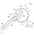
- the cooling device 20 includes a tank 22, an outflow passage 24, a passage member 26, and a sleeve-shaped component 34.
- the tank 22 has a cylindrical shape with both ends closed.
- the tank 22 is arranged above the object 100 to be cooled in a posture lying sideways.
- the attitude of the tank 22 lying sideways refers to an attitude in which the axial direction of the tank 22 is substantially perpendicular to the direction of gravity (horizontal direction).
- the coolant L is stored in the tank 22.
- Brackets 32 and 33 are attached to the lower part of the tank 22.
- the brackets 32 and 33 are metal fittings for attaching the tank 22 to the object 100 to be cooled.
- Mounting holes (not shown) for screw mounting to the object to be cooled 100 are formed in these brackets 32 and 33, respectively.
- the brackets 32 and 33 are also used when installing the tank 22 in an inspection device 50 described later, and serve as a reference for positioning the tank 22.
- the outer wall 22A is formed in a cylindrical shape, which is an example of a curved shape.
- the outflow passage 24 is a flow passage that opens into the tank 22 and allows the refrigerant L in the tank 22 to flow out of the tank 22.
- the outflow passage 24 is provided at a lower portion of the tank 22 and is configured by a pipe extending from the inside to the outside of the tank 22.
- the passage member 26 is formed in a tubular shape, and constitutes an inflow passage of the refrigerant L into the tank 22.
- the inflow path formed by the outflow path 24 and the passage member 26 constitutes a part of the circulation path CR (see FIG. 6) of the refrigerant L of the cooling device 20.
- the object to be cooled 100 is arranged on the circulation route CR.
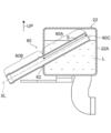
- the passage member 26 extends from the inside of the tank 22 to the outside, as shown in FIG.
- the opening end 26C of the inner portion 26A located in the tank 22 is located above the opening 24A of the outflow passage 24.
- the passage member 26 extends obliquely upward, and penetrates the curved outer wall 22 ⁇ / b> A of the tank 22.
- the inner portion 26A of the passage member 26 and the outer portion 26B described later are inserted into the insertion portion and the outer portion 26B, respectively. It may be called a non-insertion part.
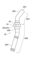
- the passage member 26 has a shape in which both ends of the pipe are bent in opposite directions, and a straight portion 26E between the bent portions 26D on both sides passes through the through hole 23.
- a portion located inside the tank 22 including the through hole 23 constitutes a part of the inner portion 26A, and a portion located outside the tank 22 with respect to the through hole 23. It constitutes a part of the outer portion 26B.
- the bent portion 26D included in the inner portion 26A of the passage member 26 is bent with respect to the linear portion 26E included in the outer portion 26B. That is, the inner portion 26A of the passage member 26 is bent with respect to the outer portion 26B.
- the bent portion 26D included in the inner portion 26A of the passage member 26 is bent upward with respect to the linear portion 26E included in the outer portion 26B.
- a cylindrical sleeve-like part 34 is mounted on the linear portion 26E of the passage member 26. Specifically, the sleeve-shaped part 34 is joined (brazed in the present embodiment) to the outer periphery of the outer part 26B located outside the tank 22 among the linear parts 26E.
- the sleeve part 34 is formed with a flange part 28 projecting radially outward from the outer periphery thereof.
- the axis of the sleeve-shaped part 34 and the axis XL of the linear portion 26E of the passage member 26 coincide with each other, and the radial direction of the sleeve-shaped part 34 and the direction orthogonal to the axis XL of the linear part 26E point in the same direction.
- the outer portion 26B includes the flange portion 28 that projects in a direction orthogonal to the axis XL.
- ⁇ ⁇ ⁇ ⁇ Flange portion 28 is formed in an annular plate shape and is in contact with outer wall 22A of tank 22. Specifically, since the outer wall 22 ⁇ / b> A has a curved surface shape, the flange portion 28 is in contact with the peripheral edge of the through hole 23. In addition, in the gap between the outer wall 22A and the flange portion 28, there is formed a wax pool in which the brazing material melted during brazing is stored.
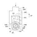
- a two-sided width portion 30 is formed on the flange portion 28 of the sleeve-shaped component 34.
- the two-plane width portion 30 is an example of a direction confirming portion capable of confirming a rotational position of the outer portion 26B around the axis XL.
- the two-plane width portion 30 has a pair of planes 30A that are opposite and parallel to each other. That is, the two-face width portion 30 is formed by linearly cutting off the opposing portion of the outer periphery of the flange portion 28.
- the tank 22, the pipe constituting the outflow passage 24, the passage member 26, the bracket 32, the bracket 33, and the sleeve-like part 34 are made of a metal material, and these members are respectively brazed. Are joined by Note that stainless steel may be used as the metal material, for example.
- a tank 22 constituting the cooling device 20 a pipe constituting the outflow passage 24, a passage member 26, a bracket 32, a bracket 33, and a sleeve-like part 34 are prepared.
- the sleeve-shaped part 34 is temporarily assembled to the passage member 26, and the passage member 26 penetrates the outer wall 22 ⁇ / b> A of the tank 22.
- the passage member 26 is inserted into the tank 22 from the through hole 23 of the outer wall 22A.
- the passage member 26 is temporarily assembled to the tank 22.
- the pipes constituting the outflow passage 24 are temporarily assembled in a state where the pipes penetrate the outer wall 22A of the tank 22.
- brackets 32 and 33 are temporarily assembled to the lower part of the tank 22.
- the temporary assembly of the above components constituting the cooling device 20 is performed in a state where the respective components are temporarily fixed by a dedicated jig.
- the cooling device 20 in the temporarily assembled state is placed in the heating furnace, and the above components are brazed and fixed.
- the cooling device 20 is manufactured as described above.
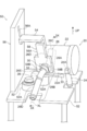
- the inspection device 50 includes an inspection table 52, an arm 54, a support wall 56, and an inspection jig 58.
- the inspection table 52 is a table for fixing the tank 22 in a posture lying on its side.
- the inspection table 52 is formed with a fixing portion 52A for fixing the brackets 32, 33 with screws.
- One end of the arm 54 is slidably supported by the support wall 56, and the other end is connected to the arm 54.
- the support wall 56 is erected on the inspection table 52.
- a slide groove 56A is formed in the support wall 56, and one end of the arm 54 inserted in the slide groove 56A is slidably supported along the slide groove 56A.
- the support wall 56 is provided with a drive source (not shown) for sliding the arm 54 along the slide groove 56A.
- the drive source include an electric motor and a fluid pressure cylinder (a hydraulic cylinder, an air cylinder, and the like).
- the inspection jig 58 includes a base 58A connected to the other end of the arm 54, and a pair of plate-shaped protrusions 58B protruding from the base 58A. Specifically, the pair of protruding portions 58B are opposed to each other, and the interval W1 between the two is not less than the width W2 of the two-sided width portion 30 and less than the outer diameter W3 of the flange portion 28.
- the brackets 32 and 33 are fixed to the inspection table 52 in a posture in which the tank 22 is laid sideways.
- the arm 54 is slid together with the inspection jig 58 toward the two-plane width portion 30 of the flange portion 28 provided on the outer portion 26B of the passage member 26. Since the width W2 of the two-sided width portion 30 is equal to or less than the interval W1 of the inspection jig 58, when the flat surface 30A constituting the two-sided width portion 30 is not inclined with respect to the reference surface along the sliding direction of the flange portion 28. As shown in FIG. 4, the width across flats 30 enters between the pair of protrusions 58B. On the other hand, when the plane 30A forming the two-sided width portion 30 is inclined with respect to the reference plane, as shown in FIG.
- the two-sided width portion 30 cannot enter between the pair of protrusions 58B. It can be confirmed that the passage member 26 is rotating. As described above, the rotational position of the outer portion 26B of the passage member 26 around the axis XL can be confirmed after brazing.
- the cooling device 20 is installed above the engine E.
- the coolant L in the tank 22 described below is pushed out by a pump (not shown), circulates through the circulation path CR, and cools the object to be cooled 100 on the circulation path CR.
- the pump also stops.
- the refrigerant L boiling due to the heat of the object to be cooled 100 accumulates in the tank 22, the refrigerant L in the tank 22 is described below due to the pressure and gravity in the tank 22. It is discharged from the outflow channel 24 according to the siphon principle.
- the pressure in the tank 22 becomes negative, and the refrigerant L is sucked into the tank 22 through a passage member 26 described later.
- the refrigerant L boiling due to the heat of the object to be cooled 100 accumulates in the tank 22, the refrigerant L in the tank 22 is discharged.
- the inner portion 26A of the passage member 26 is bent relative to the outer portion 26B, and the outer portion 26B of the passage member 26 confirms the rotational position of the outer portion 26B about the axis XL.
- a two-plane width portion 30 is provided as an example of a possible direction checking portion. The position of the open end 26C of the passage member 26 in the tank 22 can be specified by confirming the rotational position of the outer portion 26B with the two-plane width portion 30. Further, the two-face width portion 30 is provided on an outer portion 26 ⁇ / b> B located outside the tank 22, that is, is exposed outside the tank 22. Therefore, according to the cooling device 20, the position of the open end 26C of the passage member 26 in the tank 22 can be confirmed even when the inside of the tank 22 is not visible.
- the rotational position of the outer portion 26B of the passage member 26 can be confirmed by the two-face width portion 30 having a pair of planes facing and parallel to each other. That is, according to the cooling device 20, the position of the opening end 26C of the passage member 26 in the tank 22 can be accurately grasped with a simple configuration.
- a brazing pool is formed between the flange portion 28 and the outer wall 22A.
- the passage member 26 and the tank 22 are firmly joined (brazed) via the portion 28.
- the number of parts is smaller than that of, for example, a configuration in which the two-face width part is formed on another component mounted on the passage member 26, and the wax is reduced. An increase in the number of attachment points can be suppressed.
- the outer wall 22A of the tank 22 has a cylindrical surface shape, it is easy to increase the amount of brazing between the outer wall 22A and the flange portion. Thereby, the joining strength between the passage member 26 and the tank 22 can be improved.
- the cooling device 20 since the cylindrical tank 22 is disposed above the object 100 to be cooled in a posture in which the tank is laid sideways, for example, the tank 22 is disposed above the object 100 to be cooled in a posture in which the tank is raised vertically. Compared with the arrangement, a wider space can be secured above the tank in the vehicle. Further, in the cooling device 20, since the passage member 26 extends obliquely upward and penetrates the outer wall 22A of the tank 22, for example, compared with a configuration in which the passage member 26 extends upward and penetrates the bottom wall of the tank 22. , The height of the tank 22 can be reduced. This makes it possible to secure a wide space in the vehicle above the tank.
- the two-face width portion 30 is formed on the flange portion 28 of the sleeve-shaped component 34, but the present disclosure is not limited to this configuration.
- a configuration in which the flange portion 28 and the two-plane width portion 30 are provided separately may be adopted.
- the width across flats 30 is used as an example of the direction checking unit, but the present disclosure is not limited to this configuration.
- a configuration in which one flat surface is formed on the flange portion 28 may be employed. If the plane has a certain area, the rotational position of the outer portion 26B is in a prescribed state by inserting a fork-like jig similar to the inspection jig 58 described above into a portion where the plane is formed. Can be checked.
- the inclination of the plane 30A of the two-plane width portion 30 is confirmed by the inspection jig 58 of the inspection device 50, but the present disclosure is not limited to this configuration.
- the bent portion 26D of the outer portion 26B of the passage member 26 may be folded back, and the rotational position of the outer portion 26B about the axis XL may be confirmed between the bent portion 26D and the folded portion 26F.
- the bent portion functions as an example of a direction checking unit.
- the passage member 26 formed of a single pipe is provided, but the shape of the passage member 26 is not limited.
- an elbow-shaped passage member 72 joined to the tank 22 and a connection pipe 74 connected to the passage member 72 may be provided.
- Both ends of the passage member 72 are formed as cylindrical parts.
- the passage member 72 is manufactured by cutting both ends of an L-shaped metal material into a cylindrical shape, and then boring in a direction perpendicular to each other from the both ends processed into the cylindrical shape to form a passage.
- the passage member 72 includes an inner portion 72A disposed in the tank 22 and a cylindrical outer portion 72B penetrating the outer wall 22A of the tank 22 and extending from the inner portion 72A to the outside of the tank 22.
- the two-sided width portion 30 similar to the above-described embodiment is formed in the cylindrical outer portion 72B.
- the connection pipe 74 is connected to the passage member 72 by being inserted into the inner periphery of the outer portion 72B.
- the passage member 26 has a shape in which both ends of the pipe are bent in opposite directions, but the present disclosure is not limited to this configuration.
- a configuration in which the passage member 60 extends linearly, that is, a straight pipe may be used as the passage member 60.
- the outer portion 60B of the passage member 60 is provided with an overhang portion 62 for checking the length of insertion into the tank 22 (the length S of the inner portion 60A).
- the overhang portion 62 is an example of a length checking portion that functions as a specifying unit, and is a spool portion formed by compressing a pipe in the axial direction.
- a mark such as a punch or paint may be provided on the outer portion of the passage member instead of the above-described two-sided width portion or one-sided width portion, and the mark may function as an example of the direction checking unit.
- a protrusion instead of the above-described overhanging portion applied to the straight pipe, a protrusion may be provided on the outer portion 60B of the passage member 60, and the protrusion may function as an example of the length checking unit.
- the length of the inner portion 26A can be confirmed by abutting the flange portion 28 of the sleeve-shaped component 34 against the outer wall 22A of the tank 22, so that the flange portion 28 functions as an example of the length confirmation portion. It can also be done. It goes without saying that the scope of the present disclosure is not limited to these embodiments.
- a cooling device that circulates refrigerant through the object to be cooled by siphon circulation using the object to be cooled mounted on a vehicle as a heat source, A tank that is disposed above the object to be cooled and stores the refrigerant, An outflow path that opens into the tank and allows the refrigerant to flow out, A passage member extending from the inside of the tank to the outside, and an opening end of an inside portion located in the tank is located above an opening of the outflow passage; An identification unit that is provided on an outer portion of the passage member that is located outside the tank, and that can identify a position of the open end in the tank, A cooling device having:
- identification means is provided on an outer portion of the passage member located outside the tank, and the identification means can identify the position of the opening end of the passage member in the tank. For this reason, according to the cooling device, the position of the opening end of the passage member in the tank can be confirmed even if the inside of the tank is not visible.
- the passage member penetrates an outer wall of the tank, and the inner portion is bent with respect to the outer portion;
- the cooling device according to claim 1, wherein the identification unit includes a direction confirmation unit that can confirm a rotational position of the outer portion around the axis.
- the inside portion of the passage member is bent relative to the outside portion, and the outside portion of the passage member is provided with a direction confirming portion capable of confirming the rotational position of the outside portion around the axis.
- the position of the open end of the passage member in the tank changes when the outer portion rotates around the axis with respect to the tank in the passage member whose inner portion is bent with respect to the outer portion. That is, if the rotational position of the outer portion is determined, the position of the opening end of the passage member in the tank is also determined.
- the rotation position of the outer portion of the passage member can be confirmed by the direction confirmation unit, the position of the opening end of the passage member in the tank can be determined from the outside of the tank even if the inside of the tank cannot be visually observed. Can be accurately grasped.
- the rotational position of the outer portion of the passage member can be confirmed by the two-face width portion having the pair of planes facing each other and parallel to each other. That is, according to the cooling device of the supplementary note 3, the position of the opening end of the passage member in the tank can be accurately grasped by the direction checking unit having a simple configuration.
- the rotational position of the outer portion around the axis can be confirmed by positioning at two points on both sides of the curved portion of the outer portion. That is, according to the cooling device of the supplementary note 4, the position of the opening end of the passage member in the tank can be accurately grasped by the direction checking unit having a simple configuration in which the outer portion is curved.
- the passage member extends linearly and penetrates the outer wall of the tank, and the specifying unit has a length checking unit that can check a length of the inner portion along an axis. Cooling system.
- the passage member extends linearly and penetrates the outer wall of the tank, and a length checking portion that can check the length of the inner portion along the axis of the inner portion is provided on the outer portion of the passage member. Is provided. By confirming the length of the inner portion along the axis with the length confirming portion, the position of the opening end of the passage member in the tank can be accurately grasped.
- the passage member is inserted into the tank until the overhanging portion contacts the outer wall of the tank. The accuracy of the insertion length can be improved.
- the passage member extends obliquely upward and penetrates the outer wall of the tank, for example, the height of the tank is reduced as compared with a configuration in which the passage member extends upward and penetrates the bottom wall of the tank. Can be lower. This makes it possible to secure a wide space in the vehicle above the tank.
Landscapes
- Engineering & Computer Science (AREA)
- Mechanical Engineering (AREA)
- General Engineering & Computer Science (AREA)
- Chemical & Material Sciences (AREA)
- Combustion & Propulsion (AREA)
- Physics & Mathematics (AREA)
- Thermal Sciences (AREA)
- Transportation (AREA)
- Air-Conditioning For Vehicles (AREA)
- Heat-Exchange Devices With Radiators And Conduit Assemblies (AREA)
- Cooling, Air Intake And Gas Exhaust, And Fuel Tank Arrangements In Propulsion Units (AREA)
- Electric Propulsion And Braking For Vehicles (AREA)
Abstract
L'invention concerne un dispositif de refroidissement permettant de faire circuler un fluide frigorigène à travers un objet à refroidir monté sur un véhicule, le fluide frigorigène étant mis en circulation au moyen d'une circulation par siphon à l'aide de l'objet à refroidir en tant que source de chaleur. Le dispositif de refroidissement comprend : un réservoir stockant le fluide frigorigène et disposé au-dessus de l'objet à refroidir; un trajet de sortie qui s'ouvre à l'intérieur du réservoir et à travers lequel le fluide frigorigène s'écoule; un élément de passage qui s'étend de l'intérieur du réservoir vers l'extérieur et dans lequel une extrémité ouverte interne située à l'intérieur du réservoir est positionnée au-dessus de l'ouverture du trajet de sortie; et un moyen de spécification qui est disposé dans une partie externe de l'élément de passage sur l'extérieur du réservoir, et qui peut spécifier la position de l'extrémité ouverte à l'intérieur du réservoir.
Priority Applications (3)
| Application Number | Priority Date | Filing Date | Title |
|---|---|---|---|
| EP19841837.8A EP3832081B1 (fr) | 2018-07-27 | 2019-06-26 | Dispositif de refroidissement |
| US17/263,358 US11015513B1 (en) | 2018-07-27 | 2019-06-26 | Cooling device |
| CN201980050260.0A CN112601879B (zh) | 2018-07-27 | 2019-06-26 | 冷却装置 |
Applications Claiming Priority (2)
| Application Number | Priority Date | Filing Date | Title |
|---|---|---|---|
| JP2018141689A JP6681950B2 (ja) | 2018-07-27 | 2018-07-27 | 冷却装置 |
| JP2018-141689 | 2018-07-27 |
Publications (1)
| Publication Number | Publication Date |
|---|---|
| WO2020021950A1 true WO2020021950A1 (fr) | 2020-01-30 |
Family
ID=69180998
Family Applications (1)
| Application Number | Title | Priority Date | Filing Date |
|---|---|---|---|
| PCT/JP2019/025467 Ceased WO2020021950A1 (fr) | 2018-07-27 | 2019-06-26 | Dispositif de refroidissement |
Country Status (5)
| Country | Link |
|---|---|
| US (1) | US11015513B1 (fr) |
| EP (1) | EP3832081B1 (fr) |
| JP (1) | JP6681950B2 (fr) |
| CN (1) | CN112601879B (fr) |
| WO (1) | WO2020021950A1 (fr) |
Citations (7)
| Publication number | Priority date | Publication date | Assignee | Title |
|---|---|---|---|---|
| JPS509639U (fr) * | 1973-05-21 | 1975-01-31 | ||
| JPS5825618U (ja) * | 1981-08-14 | 1983-02-18 | スズキ株式会社 | 内燃機関の冷却管取付構造 |
| JPS61135929A (ja) | 1984-12-07 | 1986-06-23 | Nissan Motor Co Ltd | 過給機付内燃機関の過給機冷却装置 |
| JPH0254333U (fr) * | 1988-10-14 | 1990-04-19 | ||
| JPH0681643A (ja) * | 1992-08-31 | 1994-03-22 | Toyota Motor Corp | 内燃機関の冷却装置 |
| JPH11141336A (ja) * | 1997-10-31 | 1999-05-25 | Suzuki Motor Corp | 車両用リザーブタンク |
| JP2018141689A (ja) | 2017-02-27 | 2018-09-13 | シスメックス株式会社 | 液体送液方法および液体送液装置 |
Family Cites Families (30)
| Publication number | Priority date | Publication date | Assignee | Title |
|---|---|---|---|---|
| US1889892A (en) * | 1932-01-18 | 1932-12-06 | John H Rightmyer | Alcohol condenser for use with internal combustion engines |
| US2201314A (en) * | 1936-10-21 | 1940-05-21 | Arthur H Boettcher | Cooling system |
| US2556327A (en) * | 1948-01-13 | 1951-06-12 | Frederic W Hild | Recirculating radiator system |
| US2766200A (en) * | 1952-09-04 | 1956-10-09 | Westinghouse Electric Corp | Water heating apparatus |
| FR2281562A1 (fr) * | 1974-08-09 | 1976-03-05 | Otto & Co Gmbh Dr C | Sonde se trouvant dans une chambre a haute pression |
| US4096754A (en) * | 1977-08-26 | 1978-06-27 | E. I. Du Pont De Nemours And Company | Removable probe |
| US4177676A (en) * | 1978-05-25 | 1979-12-11 | Welker Robert H | Sensor positioning apparatus |
| SE413427B (sv) * | 1978-10-23 | 1980-05-27 | Nohab Diesel Ab | Ferskvattenkylsystem for kompressormatade forbrenningsmotorer med luftmellankylning |
| US4831886A (en) * | 1986-05-23 | 1989-05-23 | Hale Fire Pump Company | Flow indicator |
| JPS6371409A (ja) * | 1986-09-12 | 1988-03-31 | Isuzu Motors Ltd | 車両用暖房装置 |
| JPH025433U (fr) | 1988-06-15 | 1990-01-16 | ||
| JPH0224045U (fr) * | 1988-08-03 | 1990-02-16 | ||
| DE3904801A1 (de) * | 1989-02-17 | 1990-08-23 | Opel Adam Ag | Fluessigkeitskuehlsystem fuer eine aufgeladene brennkraftmaschine |
| US5199308A (en) * | 1991-01-03 | 1993-04-06 | Betz Laboratories, Inc. | Multi-functional level probe mounting device |
| US5186050A (en) * | 1991-09-25 | 1993-02-16 | Airmar Technology Corporation | Marine sensor mounting mechanism |
| US5174325A (en) * | 1992-05-14 | 1992-12-29 | Rosemount Analytical Inc. | Retraction mechanism for valve insertable sensors |
| JP3422036B2 (ja) * | 1992-07-13 | 2003-06-30 | 株式会社デンソー | 車両用冷却装置 |
| US5408836A (en) * | 1994-01-14 | 1995-04-25 | Thermo King Corporation | Methods and apparatus for operating a refrigeration system characterized by controlling engine coolant |
| US5724830A (en) * | 1995-07-19 | 1998-03-10 | Otis; Michael Tracy | Fluid induction and heat exchange device |
| US6408705B1 (en) * | 2000-11-28 | 2002-06-25 | General Electric Company | Mounting block for a proximity probe used for measuring axial movement of a rotor |
| BRPI0116200B8 (pt) * | 2000-12-15 | 2022-11-22 | Abb Technology Ltd | Método e dispositivo de diagnóstico para um comutador de derivação tendo um líquido isolante |
| CN2465123Y (zh) * | 2001-02-26 | 2001-12-12 | 杨旭东 | 无氟无压缩机热管与吸收扩散ⅱ型制冷机组 |
| US6550255B2 (en) * | 2001-03-21 | 2003-04-22 | The Coca-Cola Company | Stirling refrigeration system with a thermosiphon heat exchanger |
| CN100422667C (zh) * | 2005-06-29 | 2008-10-01 | 浙江三花制冷集团有限公司 | 器体内部用于储存冷媒的储液器 |
| DE202009011313U1 (de) * | 2009-08-14 | 2009-11-12 | Panarotto, Oliver | Speicher mit einem Wärmetauscherrohr |
| EP2557292A1 (fr) * | 2011-08-10 | 2013-02-13 | Ford Global Technologies, LLC | Moteur à combustion interne refroidi par liquide doté d'un système de turbocompression à gaz d'échappement |
| DE102012210320B3 (de) * | 2012-06-19 | 2013-09-26 | Ford Global Technologies, Llc | Flüssigkeitsgekühlte Brennkraftmaschine mit Nachlaufkühlung und Verfahren zum Betreiben einer derartigen Brennkraftmaschine |
| BE1022412B1 (nl) * | 2014-12-12 | 2016-03-24 | Cnh Industrial Belgium Nv | Transversaal gerichte koelmodule voor een oogstmachine |
| US9458759B2 (en) * | 2014-12-26 | 2016-10-04 | Ford Global Technologies, Llc | Method and system for engine cooling system control |
| US10145830B2 (en) * | 2015-12-10 | 2018-12-04 | Roger Alan FENTON | Monitoring power devices |
-
2018
- 2018-07-27 JP JP2018141689A patent/JP6681950B2/ja active Active
-
2019
- 2019-06-26 WO PCT/JP2019/025467 patent/WO2020021950A1/fr not_active Ceased
- 2019-06-26 US US17/263,358 patent/US11015513B1/en active Active
- 2019-06-26 EP EP19841837.8A patent/EP3832081B1/fr active Active
- 2019-06-26 CN CN201980050260.0A patent/CN112601879B/zh active Active
Patent Citations (7)
| Publication number | Priority date | Publication date | Assignee | Title |
|---|---|---|---|---|
| JPS509639U (fr) * | 1973-05-21 | 1975-01-31 | ||
| JPS5825618U (ja) * | 1981-08-14 | 1983-02-18 | スズキ株式会社 | 内燃機関の冷却管取付構造 |
| JPS61135929A (ja) | 1984-12-07 | 1986-06-23 | Nissan Motor Co Ltd | 過給機付内燃機関の過給機冷却装置 |
| JPH0254333U (fr) * | 1988-10-14 | 1990-04-19 | ||
| JPH0681643A (ja) * | 1992-08-31 | 1994-03-22 | Toyota Motor Corp | 内燃機関の冷却装置 |
| JPH11141336A (ja) * | 1997-10-31 | 1999-05-25 | Suzuki Motor Corp | 車両用リザーブタンク |
| JP2018141689A (ja) | 2017-02-27 | 2018-09-13 | シスメックス株式会社 | 液体送液方法および液体送液装置 |
Non-Patent Citations (1)
| Title |
|---|
| See also references of EP3832081A4 |
Also Published As
| Publication number | Publication date |
|---|---|
| EP3832081A4 (fr) | 2021-07-21 |
| EP3832081B1 (fr) | 2023-10-25 |
| JP6681950B2 (ja) | 2020-04-15 |
| CN112601879A (zh) | 2021-04-02 |
| JP2020016222A (ja) | 2020-01-30 |
| US20210156295A1 (en) | 2021-05-27 |
| US11015513B1 (en) | 2021-05-25 |
| EP3832081A1 (fr) | 2021-06-09 |
| CN112601879B (zh) | 2026-03-10 |
Similar Documents
| Publication | Publication Date | Title |
|---|---|---|
| US8261815B2 (en) | Heat exchanger, in particular charge air cooler or exhaust gas cooler for an internal combustion engine of a motor vehicle and method for manufacturing it | |
| US8561678B2 (en) | Heat exchanger tank and related apparatuses | |
| JP7097716B2 (ja) | インターフェースを含むバルブユニット | |
| US20110277976A1 (en) | Heat Exchanger Header and Related Methods and Apparatuses | |
| EP2423445B1 (fr) | Ensemble de boîtier de turbine | |
| US20170038168A1 (en) | Indirect Gas Cooler | |
| JP6273617B2 (ja) | 吸気管における給気冷却器の配置 | |
| CN206419126U (zh) | 水冷却的egr冷却器 | |
| JP2005172270A (ja) | オイルクーラ内蔵ラジエータ | |
| EP3527799B1 (fr) | Module de refroidissement | |
| CN1659368A (zh) | 废气热交换器及其制造方法 | |
| CN102272548B (zh) | 复合型换热器 | |
| WO2020021950A1 (fr) | Dispositif de refroidissement | |
| CN109944721B (zh) | 用于车辆的egr冷却器 | |
| US8875668B2 (en) | Apparatus configured to shelter oil-jet device from inadvertent installation damage | |
| CN113803254A (zh) | 一种压缩机及其制造方法 | |
| US20110139410A1 (en) | Floating Coil Heat Exchanger | |
| CN109026339A (zh) | 一种汽车混合散热水箱组件 | |
| US20180080342A1 (en) | Split turbocharger bearing assembly | |
| KR20190014213A (ko) | 차량용 egr쿨러의 설치 구조 및 방법 | |
| EP3747583A1 (fr) | Technique de soudage orbital tournée radialement vers l'extérieur en tant que procédé de jonction utilisé pour un tube interne pour connexions de fixation dans des configurations de tubes à double paroi | |
| CN107284185A (zh) | 排热回收装置 | |
| ES2324071B1 (es) | Intercambiador de calor para gases, y su correspondiente procedimiento de fabricacion. | |
| DE10155844A1 (de) | Verbrennungs-Heizeinrichtung | |
| JP2025138238A (ja) | 室外機及び空気調和機 |
Legal Events
| Date | Code | Title | Description |
|---|---|---|---|
| 121 | Ep: the epo has been informed by wipo that ep was designated in this application |
Ref document number: 19841837 Country of ref document: EP Kind code of ref document: A1 |
|
| NENP | Non-entry into the national phase |
Ref country code: DE |
|
| ENP | Entry into the national phase |
Ref document number: 2019841837 Country of ref document: EP Effective date: 20210301 |