WO2020021950A1 - 冷却装置 - Google Patents
冷却装置 Download PDFInfo
- Publication number
- WO2020021950A1 WO2020021950A1 PCT/JP2019/025467 JP2019025467W WO2020021950A1 WO 2020021950 A1 WO2020021950 A1 WO 2020021950A1 JP 2019025467 W JP2019025467 W JP 2019025467W WO 2020021950 A1 WO2020021950 A1 WO 2020021950A1
- Authority
- WO
- WIPO (PCT)
- Prior art keywords
- tank
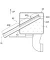
- cooling device
- passage member
- wall
- cooled
- Prior art date
- Legal status (The legal status is an assumption and is not a legal conclusion. Google has not performed a legal analysis and makes no representation as to the accuracy of the status listed.)
- Ceased
Links
Images



Classifications
-
- F—MECHANICAL ENGINEERING; LIGHTING; HEATING; WEAPONS; BLASTING
- F01—MACHINES OR ENGINES IN GENERAL; ENGINE PLANTS IN GENERAL; STEAM ENGINES
- F01P—COOLING OF MACHINES OR ENGINES IN GENERAL; COOLING OF INTERNAL-COMBUSTION ENGINES
- F01P11/00—Component parts, details, or accessories not provided for in, or of interest apart from, groups F01P1/00 - F01P9/00
- F01P11/02—Liquid-coolant filling, overflow, venting, or draining devices
- F01P11/029—Expansion reservoirs
-
- F—MECHANICAL ENGINEERING; LIGHTING; HEATING; WEAPONS; BLASTING
- F01—MACHINES OR ENGINES IN GENERAL; ENGINE PLANTS IN GENERAL; STEAM ENGINES
- F01P—COOLING OF MACHINES OR ENGINES IN GENERAL; COOLING OF INTERNAL-COMBUSTION ENGINES
- F01P3/00—Liquid cooling
- F01P3/20—Cooling circuits not specific to a single part of engine or machine
-
- B—PERFORMING OPERATIONS; TRANSPORTING
- B60—VEHICLES IN GENERAL
- B60K—ARRANGEMENT OR MOUNTING OF PROPULSION UNITS OR OF TRANSMISSIONS IN VEHICLES; ARRANGEMENT OR MOUNTING OF PLURAL DIVERSE PRIME-MOVERS IN VEHICLES; AUXILIARY DRIVES FOR VEHICLES; INSTRUMENTATION OR DASHBOARDS FOR VEHICLES; ARRANGEMENTS IN CONNECTION WITH COOLING, AIR INTAKE, GAS EXHAUST OR FUEL SUPPLY OF PROPULSION UNITS IN VEHICLES
- B60K11/00—Arrangement in connection with cooling of propulsion units
- B60K11/02—Arrangement in connection with cooling of propulsion units with liquid cooling
-
- F—MECHANICAL ENGINEERING; LIGHTING; HEATING; WEAPONS; BLASTING
- F01—MACHINES OR ENGINES IN GENERAL; ENGINE PLANTS IN GENERAL; STEAM ENGINES
- F01D—NON-POSITIVE DISPLACEMENT MACHINES OR ENGINES, e.g. STEAM TURBINES
- F01D1/00—Non-positive-displacement machines or engines, e.g. steam turbines
- F01D1/02—Non-positive-displacement machines or engines, e.g. steam turbines with stationary working-fluid guiding means and bladed or like rotor, e.g. multi-bladed impulse steam turbines
- F01D1/06—Non-positive-displacement machines or engines, e.g. steam turbines with stationary working-fluid guiding means and bladed or like rotor, e.g. multi-bladed impulse steam turbines traversed by the working-fluid substantially radially
-
- F—MECHANICAL ENGINEERING; LIGHTING; HEATING; WEAPONS; BLASTING
- F01—MACHINES OR ENGINES IN GENERAL; ENGINE PLANTS IN GENERAL; STEAM ENGINES
- F01P—COOLING OF MACHINES OR ENGINES IN GENERAL; COOLING OF INTERNAL-COMBUSTION ENGINES
- F01P11/00—Component parts, details, or accessories not provided for in, or of interest apart from, groups F01P1/00 - F01P9/00
- F01P11/02—Liquid-coolant filling, overflow, venting, or draining devices
- F01P11/0276—Draining or purging
-
- F—MECHANICAL ENGINEERING; LIGHTING; HEATING; WEAPONS; BLASTING
- F01—MACHINES OR ENGINES IN GENERAL; ENGINE PLANTS IN GENERAL; STEAM ENGINES
- F01P—COOLING OF MACHINES OR ENGINES IN GENERAL; COOLING OF INTERNAL-COMBUSTION ENGINES
- F01P11/00—Component parts, details, or accessories not provided for in, or of interest apart from, groups F01P1/00 - F01P9/00
- F01P11/04—Arrangements of liquid pipes or hoses
-
- F—MECHANICAL ENGINEERING; LIGHTING; HEATING; WEAPONS; BLASTING
- F01—MACHINES OR ENGINES IN GENERAL; ENGINE PLANTS IN GENERAL; STEAM ENGINES
- F01P—COOLING OF MACHINES OR ENGINES IN GENERAL; COOLING OF INTERNAL-COMBUSTION ENGINES
- F01P11/00—Component parts, details, or accessories not provided for in, or of interest apart from, groups F01P1/00 - F01P9/00
- F01P11/14—Indicating devices; Other safety devices
-
- F—MECHANICAL ENGINEERING; LIGHTING; HEATING; WEAPONS; BLASTING
- F28—HEAT EXCHANGE IN GENERAL
- F28F—DETAILS OF HEAT-EXCHANGE AND HEAT-TRANSFER APPARATUS, OF GENERAL APPLICATION
- F28F13/00—Arrangements for modifying heat-transfer, e.g. increasing, decreasing
- F28F13/06—Arrangements for modifying heat-transfer, e.g. increasing, decreasing by affecting the pattern of flow of the heat-exchange media
-
- F—MECHANICAL ENGINEERING; LIGHTING; HEATING; WEAPONS; BLASTING
- F01—MACHINES OR ENGINES IN GENERAL; ENGINE PLANTS IN GENERAL; STEAM ENGINES
- F01D—NON-POSITIVE DISPLACEMENT MACHINES OR ENGINES, e.g. STEAM TURBINES
- F01D1/00—Non-positive-displacement machines or engines, e.g. steam turbines
- F01D1/02—Non-positive-displacement machines or engines, e.g. steam turbines with stationary working-fluid guiding means and bladed or like rotor, e.g. multi-bladed impulse steam turbines
-
- F—MECHANICAL ENGINEERING; LIGHTING; HEATING; WEAPONS; BLASTING
- F01—MACHINES OR ENGINES IN GENERAL; ENGINE PLANTS IN GENERAL; STEAM ENGINES
- F01P—COOLING OF MACHINES OR ENGINES IN GENERAL; COOLING OF INTERNAL-COMBUSTION ENGINES
- F01P11/00—Component parts, details, or accessories not provided for in, or of interest apart from, groups F01P1/00 - F01P9/00
- F01P11/14—Indicating devices; Other safety devices
- F01P11/18—Indicating devices; Other safety devices concerning coolant pressure, coolant flow, or liquid-coolant level
-
- F—MECHANICAL ENGINEERING; LIGHTING; HEATING; WEAPONS; BLASTING
- F01—MACHINES OR ENGINES IN GENERAL; ENGINE PLANTS IN GENERAL; STEAM ENGINES
- F01P—COOLING OF MACHINES OR ENGINES IN GENERAL; COOLING OF INTERNAL-COMBUSTION ENGINES
- F01P2031/00—Fail safe
- F01P2031/30—Cooling after the engine is stopped
-
- F—MECHANICAL ENGINEERING; LIGHTING; HEATING; WEAPONS; BLASTING
- F01—MACHINES OR ENGINES IN GENERAL; ENGINE PLANTS IN GENERAL; STEAM ENGINES
- F01P—COOLING OF MACHINES OR ENGINES IN GENERAL; COOLING OF INTERNAL-COMBUSTION ENGINES
- F01P2050/00—Applications
- F01P2050/24—Hybrid vehicles
-
- F—MECHANICAL ENGINEERING; LIGHTING; HEATING; WEAPONS; BLASTING
- F01—MACHINES OR ENGINES IN GENERAL; ENGINE PLANTS IN GENERAL; STEAM ENGINES
- F01P—COOLING OF MACHINES OR ENGINES IN GENERAL; COOLING OF INTERNAL-COMBUSTION ENGINES
- F01P2060/00—Cooling circuits using auxiliaries
- F01P2060/12—Turbo charger
-
- F—MECHANICAL ENGINEERING; LIGHTING; HEATING; WEAPONS; BLASTING
- F01—MACHINES OR ENGINES IN GENERAL; ENGINE PLANTS IN GENERAL; STEAM ENGINES
- F01P—COOLING OF MACHINES OR ENGINES IN GENERAL; COOLING OF INTERNAL-COMBUSTION ENGINES
- F01P2060/00—Cooling circuits using auxiliaries
- F01P2060/16—Outlet manifold
-
- F—MECHANICAL ENGINEERING; LIGHTING; HEATING; WEAPONS; BLASTING
- F28—HEAT EXCHANGE IN GENERAL
- F28D—HEAT-EXCHANGE APPARATUS, NOT PROVIDED FOR IN ANOTHER SUBCLASS, IN WHICH THE HEAT-EXCHANGE MEDIA DO NOT COME INTO DIRECT CONTACT
- F28D1/00—Heat-exchange apparatus having stationary conduit assemblies for one heat-exchange medium only, the media being in contact with different sides of the conduit wall, in which the other heat-exchange medium is a large body of fluid, e.g. domestic or motor car radiators
- F28D1/06—Heat-exchange apparatus having stationary conduit assemblies for one heat-exchange medium only, the media being in contact with different sides of the conduit wall, in which the other heat-exchange medium is a large body of fluid, e.g. domestic or motor car radiators with the heat-exchange conduits forming part of, or being attached to, the tank containing the body of fluid
Definitions
- the present disclosure relates to a cooling device for cooling an object to be cooled mounted on a vehicle.
- JP-A-61-135929 discloses that a cooling water storage tank connected to a downstream side of a supercharger cooling passage is installed at a higher position than a supercharger, and cooling water is circulated using a thermosiphon. Discloses a technique for continuing cooling of a turbocharger without power supply even after an engine stop.
- JP-A-61-135929 a pipe is inserted into the tank through the bottom wall of the cooling water storage tank. After assembling the cooling water storage tank and the pipe, the inside of the tank cannot be visually observed, so that the position of the opening end of the pipe in the tank cannot be confirmed.
- the present disclosure has a configuration in which a passage member extends from the inside to the outside of a tank, and a cooling device that can confirm the position of the opening end of the passage member in the tank even when the inside of the tank is not visible.
- the task is to provide
- a cooling device is a cooling device that circulates a refrigerant through the object to be cooled by siphon circulation using the object to be cooled mounted on a vehicle as a heat source. And an outflow path that opens into the tank and allows the refrigerant to flow out, extends from the inside of the tank to the outside, and an open end of an inner portion located in the tank is closer to the opening of the outflow path than the opening of the outflow path.
- a passage member that is located above, and an identification unit that is provided on an outer portion of the passage member that is located outside the tank and that can identify the position of the open end in the tank.
- the passage member extends from the inside of the tank to the outside, even if the inside of the tank is not visible, the position of the opening end of the passage member in the tank can be confirmed.
- An apparatus can be provided.
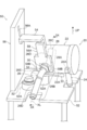
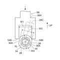
- FIG. 2 is a front view of an inspection part showing a favorable state in a result of inspection of a direction of a passage member by an inspection jig of the inspection device shown in FIG. 1.
- FIG. 2 is a front view of an inspection portion showing a state in which a result of inspecting a direction of a passage member using an inspection jig of the inspection device shown in FIG. 1 is not good.
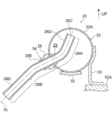
- FIG. 4 is a cross-sectional view (a cross-sectional view corresponding to FIG.
- FIG. 6 is a cross-sectional view (a cross-sectional view corresponding to FIG. 3) illustrating a state in which a cooling device according to another embodiment of the present disclosure is set in another inspection device.
- FIG. 6 is a cross-sectional view (a cross-sectional view corresponding to FIG. 3) illustrating a state in which a cooling device according to another embodiment of the present disclosure is set in an inspection device.
- FIG. 6 is a cross-sectional view (a cross-sectional view corresponding to FIG. 3) illustrating a state in which a cooling device according to another embodiment of the present disclosure is set in an inspection device.
- the cooling device 20 of the present embodiment is a device that circulates a refrigerant to the object to be cooled 100 by siphon circulation using the object to be cooled 100 (see FIG. 6) mounted on the vehicle as a heat source.
- the object to be cooled 100 is a turbocharger, an exhaust gas recirculation cooler (EGR cooler), an electric motor applied to an EV or HV, a rotating electric machine such as a generator and a motor generator, a range extender applied to an EV, and an internal combustion engine. Institutions and the like.
- the target to which the residual heat after the vehicle stops can be a heat source for the siphon circulation can be set as the target 100 to be cooled.
- the object to be cooled 100 of the present embodiment is a turbocharger.
- the cooling device 20 includes a tank 22, an outflow passage 24, a passage member 26, and a sleeve-shaped component 34.
- the tank 22 has a cylindrical shape with both ends closed.
- the tank 22 is arranged above the object 100 to be cooled in a posture lying sideways.
- the attitude of the tank 22 lying sideways refers to an attitude in which the axial direction of the tank 22 is substantially perpendicular to the direction of gravity (horizontal direction).
- the coolant L is stored in the tank 22.
- Brackets 32 and 33 are attached to the lower part of the tank 22.
- the brackets 32 and 33 are metal fittings for attaching the tank 22 to the object 100 to be cooled.
- Mounting holes (not shown) for screw mounting to the object to be cooled 100 are formed in these brackets 32 and 33, respectively.
- the brackets 32 and 33 are also used when installing the tank 22 in an inspection device 50 described later, and serve as a reference for positioning the tank 22.
- the outer wall 22A is formed in a cylindrical shape, which is an example of a curved shape.
- the outflow passage 24 is a flow passage that opens into the tank 22 and allows the refrigerant L in the tank 22 to flow out of the tank 22.
- the outflow passage 24 is provided at a lower portion of the tank 22 and is configured by a pipe extending from the inside to the outside of the tank 22.
- the passage member 26 is formed in a tubular shape, and constitutes an inflow passage of the refrigerant L into the tank 22.
- the inflow path formed by the outflow path 24 and the passage member 26 constitutes a part of the circulation path CR (see FIG. 6) of the refrigerant L of the cooling device 20.
- the object to be cooled 100 is arranged on the circulation route CR.
- the passage member 26 extends from the inside of the tank 22 to the outside, as shown in FIG.
- the opening end 26C of the inner portion 26A located in the tank 22 is located above the opening 24A of the outflow passage 24.
- the passage member 26 extends obliquely upward, and penetrates the curved outer wall 22 ⁇ / b> A of the tank 22.
- the inner portion 26A of the passage member 26 and the outer portion 26B described later are inserted into the insertion portion and the outer portion 26B, respectively. It may be called a non-insertion part.
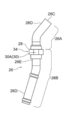
- the passage member 26 has a shape in which both ends of the pipe are bent in opposite directions, and a straight portion 26E between the bent portions 26D on both sides passes through the through hole 23.
- a portion located inside the tank 22 including the through hole 23 constitutes a part of the inner portion 26A, and a portion located outside the tank 22 with respect to the through hole 23. It constitutes a part of the outer portion 26B.
- the bent portion 26D included in the inner portion 26A of the passage member 26 is bent with respect to the linear portion 26E included in the outer portion 26B. That is, the inner portion 26A of the passage member 26 is bent with respect to the outer portion 26B.
- the bent portion 26D included in the inner portion 26A of the passage member 26 is bent upward with respect to the linear portion 26E included in the outer portion 26B.
- a cylindrical sleeve-like part 34 is mounted on the linear portion 26E of the passage member 26. Specifically, the sleeve-shaped part 34 is joined (brazed in the present embodiment) to the outer periphery of the outer part 26B located outside the tank 22 among the linear parts 26E.
- the sleeve part 34 is formed with a flange part 28 projecting radially outward from the outer periphery thereof.
- the axis of the sleeve-shaped part 34 and the axis XL of the linear portion 26E of the passage member 26 coincide with each other, and the radial direction of the sleeve-shaped part 34 and the direction orthogonal to the axis XL of the linear part 26E point in the same direction.
- the outer portion 26B includes the flange portion 28 that projects in a direction orthogonal to the axis XL.
- ⁇ ⁇ ⁇ ⁇ Flange portion 28 is formed in an annular plate shape and is in contact with outer wall 22A of tank 22. Specifically, since the outer wall 22 ⁇ / b> A has a curved surface shape, the flange portion 28 is in contact with the peripheral edge of the through hole 23. In addition, in the gap between the outer wall 22A and the flange portion 28, there is formed a wax pool in which the brazing material melted during brazing is stored.
- a two-sided width portion 30 is formed on the flange portion 28 of the sleeve-shaped component 34.
- the two-plane width portion 30 is an example of a direction confirming portion capable of confirming a rotational position of the outer portion 26B around the axis XL.
- the two-plane width portion 30 has a pair of planes 30A that are opposite and parallel to each other. That is, the two-face width portion 30 is formed by linearly cutting off the opposing portion of the outer periphery of the flange portion 28.
- the tank 22, the pipe constituting the outflow passage 24, the passage member 26, the bracket 32, the bracket 33, and the sleeve-like part 34 are made of a metal material, and these members are respectively brazed. Are joined by Note that stainless steel may be used as the metal material, for example.
- a tank 22 constituting the cooling device 20 a pipe constituting the outflow passage 24, a passage member 26, a bracket 32, a bracket 33, and a sleeve-like part 34 are prepared.
- the sleeve-shaped part 34 is temporarily assembled to the passage member 26, and the passage member 26 penetrates the outer wall 22 ⁇ / b> A of the tank 22.
- the passage member 26 is inserted into the tank 22 from the through hole 23 of the outer wall 22A.
- the passage member 26 is temporarily assembled to the tank 22.
- the pipes constituting the outflow passage 24 are temporarily assembled in a state where the pipes penetrate the outer wall 22A of the tank 22.
- brackets 32 and 33 are temporarily assembled to the lower part of the tank 22.
- the temporary assembly of the above components constituting the cooling device 20 is performed in a state where the respective components are temporarily fixed by a dedicated jig.
- the cooling device 20 in the temporarily assembled state is placed in the heating furnace, and the above components are brazed and fixed.
- the cooling device 20 is manufactured as described above.
- the inspection device 50 includes an inspection table 52, an arm 54, a support wall 56, and an inspection jig 58.
- the inspection table 52 is a table for fixing the tank 22 in a posture lying on its side.
- the inspection table 52 is formed with a fixing portion 52A for fixing the brackets 32, 33 with screws.
- One end of the arm 54 is slidably supported by the support wall 56, and the other end is connected to the arm 54.
- the support wall 56 is erected on the inspection table 52.
- a slide groove 56A is formed in the support wall 56, and one end of the arm 54 inserted in the slide groove 56A is slidably supported along the slide groove 56A.
- the support wall 56 is provided with a drive source (not shown) for sliding the arm 54 along the slide groove 56A.
- the drive source include an electric motor and a fluid pressure cylinder (a hydraulic cylinder, an air cylinder, and the like).
- the inspection jig 58 includes a base 58A connected to the other end of the arm 54, and a pair of plate-shaped protrusions 58B protruding from the base 58A. Specifically, the pair of protruding portions 58B are opposed to each other, and the interval W1 between the two is not less than the width W2 of the two-sided width portion 30 and less than the outer diameter W3 of the flange portion 28.
- the brackets 32 and 33 are fixed to the inspection table 52 in a posture in which the tank 22 is laid sideways.
- the arm 54 is slid together with the inspection jig 58 toward the two-plane width portion 30 of the flange portion 28 provided on the outer portion 26B of the passage member 26. Since the width W2 of the two-sided width portion 30 is equal to or less than the interval W1 of the inspection jig 58, when the flat surface 30A constituting the two-sided width portion 30 is not inclined with respect to the reference surface along the sliding direction of the flange portion 28. As shown in FIG. 4, the width across flats 30 enters between the pair of protrusions 58B. On the other hand, when the plane 30A forming the two-sided width portion 30 is inclined with respect to the reference plane, as shown in FIG.
- the two-sided width portion 30 cannot enter between the pair of protrusions 58B. It can be confirmed that the passage member 26 is rotating. As described above, the rotational position of the outer portion 26B of the passage member 26 around the axis XL can be confirmed after brazing.
- the cooling device 20 is installed above the engine E.
- the coolant L in the tank 22 described below is pushed out by a pump (not shown), circulates through the circulation path CR, and cools the object to be cooled 100 on the circulation path CR.
- the pump also stops.
- the refrigerant L boiling due to the heat of the object to be cooled 100 accumulates in the tank 22, the refrigerant L in the tank 22 is described below due to the pressure and gravity in the tank 22. It is discharged from the outflow channel 24 according to the siphon principle.
- the pressure in the tank 22 becomes negative, and the refrigerant L is sucked into the tank 22 through a passage member 26 described later.
- the refrigerant L boiling due to the heat of the object to be cooled 100 accumulates in the tank 22, the refrigerant L in the tank 22 is discharged.
- the inner portion 26A of the passage member 26 is bent relative to the outer portion 26B, and the outer portion 26B of the passage member 26 confirms the rotational position of the outer portion 26B about the axis XL.
- a two-plane width portion 30 is provided as an example of a possible direction checking portion. The position of the open end 26C of the passage member 26 in the tank 22 can be specified by confirming the rotational position of the outer portion 26B with the two-plane width portion 30. Further, the two-face width portion 30 is provided on an outer portion 26 ⁇ / b> B located outside the tank 22, that is, is exposed outside the tank 22. Therefore, according to the cooling device 20, the position of the open end 26C of the passage member 26 in the tank 22 can be confirmed even when the inside of the tank 22 is not visible.
- the rotational position of the outer portion 26B of the passage member 26 can be confirmed by the two-face width portion 30 having a pair of planes facing and parallel to each other. That is, according to the cooling device 20, the position of the opening end 26C of the passage member 26 in the tank 22 can be accurately grasped with a simple configuration.
- a brazing pool is formed between the flange portion 28 and the outer wall 22A.
- the passage member 26 and the tank 22 are firmly joined (brazed) via the portion 28.
- the number of parts is smaller than that of, for example, a configuration in which the two-face width part is formed on another component mounted on the passage member 26, and the wax is reduced. An increase in the number of attachment points can be suppressed.
- the outer wall 22A of the tank 22 has a cylindrical surface shape, it is easy to increase the amount of brazing between the outer wall 22A and the flange portion. Thereby, the joining strength between the passage member 26 and the tank 22 can be improved.
- the cooling device 20 since the cylindrical tank 22 is disposed above the object 100 to be cooled in a posture in which the tank is laid sideways, for example, the tank 22 is disposed above the object 100 to be cooled in a posture in which the tank is raised vertically. Compared with the arrangement, a wider space can be secured above the tank in the vehicle. Further, in the cooling device 20, since the passage member 26 extends obliquely upward and penetrates the outer wall 22A of the tank 22, for example, compared with a configuration in which the passage member 26 extends upward and penetrates the bottom wall of the tank 22. , The height of the tank 22 can be reduced. This makes it possible to secure a wide space in the vehicle above the tank.
- the two-face width portion 30 is formed on the flange portion 28 of the sleeve-shaped component 34, but the present disclosure is not limited to this configuration.
- a configuration in which the flange portion 28 and the two-plane width portion 30 are provided separately may be adopted.
- the width across flats 30 is used as an example of the direction checking unit, but the present disclosure is not limited to this configuration.
- a configuration in which one flat surface is formed on the flange portion 28 may be employed. If the plane has a certain area, the rotational position of the outer portion 26B is in a prescribed state by inserting a fork-like jig similar to the inspection jig 58 described above into a portion where the plane is formed. Can be checked.
- the inclination of the plane 30A of the two-plane width portion 30 is confirmed by the inspection jig 58 of the inspection device 50, but the present disclosure is not limited to this configuration.
- the bent portion 26D of the outer portion 26B of the passage member 26 may be folded back, and the rotational position of the outer portion 26B about the axis XL may be confirmed between the bent portion 26D and the folded portion 26F.
- the bent portion functions as an example of a direction checking unit.
- the passage member 26 formed of a single pipe is provided, but the shape of the passage member 26 is not limited.
- an elbow-shaped passage member 72 joined to the tank 22 and a connection pipe 74 connected to the passage member 72 may be provided.
- Both ends of the passage member 72 are formed as cylindrical parts.
- the passage member 72 is manufactured by cutting both ends of an L-shaped metal material into a cylindrical shape, and then boring in a direction perpendicular to each other from the both ends processed into the cylindrical shape to form a passage.
- the passage member 72 includes an inner portion 72A disposed in the tank 22 and a cylindrical outer portion 72B penetrating the outer wall 22A of the tank 22 and extending from the inner portion 72A to the outside of the tank 22.
- the two-sided width portion 30 similar to the above-described embodiment is formed in the cylindrical outer portion 72B.
- the connection pipe 74 is connected to the passage member 72 by being inserted into the inner periphery of the outer portion 72B.
- the passage member 26 has a shape in which both ends of the pipe are bent in opposite directions, but the present disclosure is not limited to this configuration.
- a configuration in which the passage member 60 extends linearly, that is, a straight pipe may be used as the passage member 60.
- the outer portion 60B of the passage member 60 is provided with an overhang portion 62 for checking the length of insertion into the tank 22 (the length S of the inner portion 60A).
- the overhang portion 62 is an example of a length checking portion that functions as a specifying unit, and is a spool portion formed by compressing a pipe in the axial direction.
- a mark such as a punch or paint may be provided on the outer portion of the passage member instead of the above-described two-sided width portion or one-sided width portion, and the mark may function as an example of the direction checking unit.
- a protrusion instead of the above-described overhanging portion applied to the straight pipe, a protrusion may be provided on the outer portion 60B of the passage member 60, and the protrusion may function as an example of the length checking unit.
- the length of the inner portion 26A can be confirmed by abutting the flange portion 28 of the sleeve-shaped component 34 against the outer wall 22A of the tank 22, so that the flange portion 28 functions as an example of the length confirmation portion. It can also be done. It goes without saying that the scope of the present disclosure is not limited to these embodiments.
- a cooling device that circulates refrigerant through the object to be cooled by siphon circulation using the object to be cooled mounted on a vehicle as a heat source, A tank that is disposed above the object to be cooled and stores the refrigerant, An outflow path that opens into the tank and allows the refrigerant to flow out, A passage member extending from the inside of the tank to the outside, and an opening end of an inside portion located in the tank is located above an opening of the outflow passage; An identification unit that is provided on an outer portion of the passage member that is located outside the tank, and that can identify a position of the open end in the tank, A cooling device having:
- identification means is provided on an outer portion of the passage member located outside the tank, and the identification means can identify the position of the opening end of the passage member in the tank. For this reason, according to the cooling device, the position of the opening end of the passage member in the tank can be confirmed even if the inside of the tank is not visible.
- the passage member penetrates an outer wall of the tank, and the inner portion is bent with respect to the outer portion;
- the cooling device according to claim 1, wherein the identification unit includes a direction confirmation unit that can confirm a rotational position of the outer portion around the axis.
- the inside portion of the passage member is bent relative to the outside portion, and the outside portion of the passage member is provided with a direction confirming portion capable of confirming the rotational position of the outside portion around the axis.
- the position of the open end of the passage member in the tank changes when the outer portion rotates around the axis with respect to the tank in the passage member whose inner portion is bent with respect to the outer portion. That is, if the rotational position of the outer portion is determined, the position of the opening end of the passage member in the tank is also determined.
- the rotation position of the outer portion of the passage member can be confirmed by the direction confirmation unit, the position of the opening end of the passage member in the tank can be determined from the outside of the tank even if the inside of the tank cannot be visually observed. Can be accurately grasped.
- the rotational position of the outer portion of the passage member can be confirmed by the two-face width portion having the pair of planes facing each other and parallel to each other. That is, according to the cooling device of the supplementary note 3, the position of the opening end of the passage member in the tank can be accurately grasped by the direction checking unit having a simple configuration.
- the rotational position of the outer portion around the axis can be confirmed by positioning at two points on both sides of the curved portion of the outer portion. That is, according to the cooling device of the supplementary note 4, the position of the opening end of the passage member in the tank can be accurately grasped by the direction checking unit having a simple configuration in which the outer portion is curved.
- the passage member extends linearly and penetrates the outer wall of the tank, and the specifying unit has a length checking unit that can check a length of the inner portion along an axis. Cooling system.
- the passage member extends linearly and penetrates the outer wall of the tank, and a length checking portion that can check the length of the inner portion along the axis of the inner portion is provided on the outer portion of the passage member. Is provided. By confirming the length of the inner portion along the axis with the length confirming portion, the position of the opening end of the passage member in the tank can be accurately grasped.
- the passage member is inserted into the tank until the overhanging portion contacts the outer wall of the tank. The accuracy of the insertion length can be improved.
- the passage member extends obliquely upward and penetrates the outer wall of the tank, for example, the height of the tank is reduced as compared with a configuration in which the passage member extends upward and penetrates the bottom wall of the tank. Can be lower. This makes it possible to secure a wide space in the vehicle above the tank.
Landscapes
- Engineering & Computer Science (AREA)
- Mechanical Engineering (AREA)
- General Engineering & Computer Science (AREA)
- Chemical & Material Sciences (AREA)
- Combustion & Propulsion (AREA)
- Physics & Mathematics (AREA)
- Thermal Sciences (AREA)
- Transportation (AREA)
- Air-Conditioning For Vehicles (AREA)
- Heat-Exchange Devices With Radiators And Conduit Assemblies (AREA)
- Cooling, Air Intake And Gas Exhaust, And Fuel Tank Arrangements In Propulsion Units (AREA)
- Electric Propulsion And Braking For Vehicles (AREA)
Abstract
冷却装置は、車両に搭載される被冷却対象を熱源としたサイフォン循環により前記被冷却対象に冷媒を循環させる冷却装置において、前記被冷却対象の上方に配置され、前記冷媒を貯留するタンクと、前記タンク内に開口し、前記冷媒を流出させる流出路と、前記タンクの内側から外側へ延出し、前記タンク内に位置する内側部分の開口端が前記流出路の開口よりも上方に位置する通路部材と、前記通路部材の前記タンクの外側に位置する外側部分に備えられ、前記タンク内における前記開口端の位置を特定可能な特定手段と、を有する。
Description
本開示は、車両に搭載された被冷却対象を冷却するための冷却装置に関する。
特開昭61-135929号公報には、過給機冷却通路の下流側に接続される冷却水貯留タンクを過給機より高い所に設置し、熱サイフォンを利用して冷却水を循環させて、エンジン停止後も無給電で過給機の冷却を継続する技術について開示されている。
特開昭61-135929号公報では、冷却水貯留タンクの底壁を貫通してパイプがタンク内に挿入されている。冷却水貯溜タンクとパイプ等の組み立て後は、タンク内を目視できないため、タンク内におけるパイプの開口端の位置を確認することができない。
本開示は、上記事実を考慮して、タンクの内側から外側へ通路部材が延出する構成において、タンク内が目視できなくても、タンク内における通路部材の開口端の位置を確認できる冷却装置を提供することを課題とする。
本開示の一態様の冷却装置は、車両に搭載される被冷却対象を熱源としたサイフォン循環により前記被冷却対象に冷媒を循環させる冷却装置において、前記被冷却対象の上方に配置され、前記冷媒を貯留するタンクと、前記タンク内に開口し、前記冷媒を流出させる流出路と、前記タンクの内側から外側へ延出し、前記タンク内に位置する内側部分の開口端が前記流出路の開口よりも上方に位置する通路部材と、前記通路部材の前記タンクの外側に位置する外側部分に備えられ、前記タンク内における前記開口端の位置を特定可能な特定手段と、を有する。
以上説明したように、本開示によれば、タンクの内側から外側へ通路部材が延出する構成において、タンク内が目視できなくても、タンク内における通路部材の開口端の位置を確認できる冷却装置を提供することができる。
以下、図面を参照しながら本開示に係る一実施形態の冷却装置について説明する。なお、各図において適宜図示される矢印UPは、重力方向における上方を示している。また、以下において上方と言うときは、重力方向における上方側を指す。
本実施形態の冷却装置20は、車両に搭載される被冷却対象100(図6参照)を熱源としたサイフォン循環により被冷却対象100に冷媒を循環させる装置である。
被冷却対象100としては、ターボチャージャ、排ガス再循環クーラ(EGRクーラ)、EVやHVに適用される電動モータ、発電機、及びモータジェネレータ等の回転電機、EVに適用されるレンジエクステンダー、並びに内燃機関等が挙げられる。つまり車両停止後の余熱がサイフォン循環の熱源となり得る対象を被冷却対象100とすることができる。なお、本実施形態の被冷却対象100は、ターボチャージャである。
図1及び図6に示されるように、冷却装置20は、タンク22と、流出路24と、通路部材26と、スリーブ状部品34と、を有している。
(タンク)
タンク22は、両端が塞がれた円筒状とされている。このタンク22は、横向きに寝かされた姿勢で被冷却対象100の上方に配置されるようになっている。なお、ここでいうタンク22の横向きに寝かされた姿勢とは、タンク22の軸方向が重力方向に対して略直交する方向(横向き)となる姿勢を指している。また、タンク22の内部には、冷媒Lが貯溜されるようになっている。
タンク22は、両端が塞がれた円筒状とされている。このタンク22は、横向きに寝かされた姿勢で被冷却対象100の上方に配置されるようになっている。なお、ここでいうタンク22の横向きに寝かされた姿勢とは、タンク22の軸方向が重力方向に対して略直交する方向(横向き)となる姿勢を指している。また、タンク22の内部には、冷媒Lが貯溜されるようになっている。
また、タンク22の下部には、ブラケット32、33が取り付けられている。ブラケット32、33は、被冷却対象100にタンク22を取り付けるための金具である。これらのブラケット32、33には、被冷却対象100へのねじ取付用の取付孔(不図示)がそれぞれ形成されている。また、ブラケット32、33は、タンク22を後述する検査装置50に設置する際にも用いられ、タンク22を位置決めする基準となる。
なお、本実施形態のタンク22は、円筒状とされているため、外壁22Aが曲面状の一例である円筒面状に形成されている。
(流出路)
図1及び図3に示されるように、流出路24は、タンク22内に開口し、タンク22内の冷媒Lをタンク22の外側へ流出させるための流路である。この流出路24は、タンク22の下部に設けられ、タンク22の内側から外側へ延出する配管によって構成されている。
図1及び図3に示されるように、流出路24は、タンク22内に開口し、タンク22内の冷媒Lをタンク22の外側へ流出させるための流路である。この流出路24は、タンク22の下部に設けられ、タンク22の内側から外側へ延出する配管によって構成されている。
(通路部材)
図1及び図3に示されるように、通路部材26は、管状に形成されており、タンク22内への冷媒Lの流入路を構成している。なお、流出路24と通路部材26とによって構成される流入路は、冷却装置20の冷媒Lの循環経路CR(図6参照)の一部を構成している。この循環経路CR上に被冷却対象100が配置されるようになっている。
図1及び図3に示されるように、通路部材26は、管状に形成されており、タンク22内への冷媒Lの流入路を構成している。なお、流出路24と通路部材26とによって構成される流入路は、冷却装置20の冷媒Lの循環経路CR(図6参照)の一部を構成している。この循環経路CR上に被冷却対象100が配置されるようになっている。
通路部材26は、図3に示されるように、タンク22の内側から外側へ延出している。
また、通路部材26は、タンク22内に位置する内側部分26Aの開口端26Cが流出路24の開口24Aよりも上方に位置している。具体的には、通路部材26は、斜め上向きに延びており、タンク22の曲面形状とされた外壁22Aを貫通している。なお、本実施形態では、通路部材26は、外壁22Aに形成された貫通孔23からタンク22内へ挿入されているため、通路部材26の内側部分26A及び後述する外側部分26Bをそれぞれ挿入部分及び非挿入部分と言い換えてもよい。
また、通路部材26は、タンク22内に位置する内側部分26Aの開口端26Cが流出路24の開口24Aよりも上方に位置している。具体的には、通路部材26は、斜め上向きに延びており、タンク22の曲面形状とされた外壁22Aを貫通している。なお、本実施形態では、通路部材26は、外壁22Aに形成された貫通孔23からタンク22内へ挿入されているため、通路部材26の内側部分26A及び後述する外側部分26Bをそれぞれ挿入部分及び非挿入部分と言い換えてもよい。
図2に示されるように、通路部材26は、パイプの両端を互いに逆向きに曲げた形状とされており、両側の曲げ部26D間の直線状部分26Eが貫通孔23を貫通している。通路部材26の直線状部分26Eのうち、貫通孔23を含めてタンク22の内側に位置する部分が内側部分26Aの一部を構成し、貫通孔23よりもタンク22の外側に位置する部分が外側部分26Bの一部を構成している。なお、本実施形態では、通路部材26の内側部分26Aに含まれる曲げ部26Dが外側部分26Bに含まれる直線状部分26Eに対して曲がっている。すなわち、通路部材26の内側部分26Aが外側部分26Bに対して曲がっている。具体的には、通路部材26の内側部分26Aに含まれる曲げ部26Dは、外側部分26Bに含まれる直線状部分26Eに対して上方に向けて曲がっている。
(スリーブ状部品)
通路部材26の直線状部分26E上には、円筒状のスリーブ状部品34が装着されている。具体的には、スリーブ状部品34は、直線状部分26Eのうち、タンク22の外側に位置する外側部分26Bの外周に接合(本実施形態ではろう付け)されている。
通路部材26の直線状部分26E上には、円筒状のスリーブ状部品34が装着されている。具体的には、スリーブ状部品34は、直線状部分26Eのうち、タンク22の外側に位置する外側部分26Bの外周に接合(本実施形態ではろう付け)されている。
スリーブ状部品34には、その外周から径方向外側へ張り出すフランジ部28が形成されている。スリーブ状部品34の軸線と通路部材26の直線状部分26Eにおける軸線XLは一致しており、スリーブ状部品34の径方向と直線状部分26Eにおける軸線XLと直交する方向は同じ方向を指している。すなわち、本実施形態では、外側部分26Bが軸線XLと直交する方向に張り出すフランジ部28を備えている。
また、フランジ部28は、円環板状に形成されており、タンク22の外壁22Aに接している。具体的には、外壁22Aが曲面形状とされているため、フランジ部28は、貫通孔23の周縁部に接している。なお、外壁22Aとフランジ部28との間の隙間には、ろう付け時に溶融したろう材が溜まるろう溜まりが形成されている。
図4に示されるように、スリーブ状部品34のフランジ部28には二面幅部30が形成されている。二面幅部30は、外側部分26Bの軸線XL回りの回転位置を確認可能な方向確認部の一例である。
二面幅部30は、互いに反対向きかつ平行な一対の平面30Aを有している。すなわち、二面幅部30は、フランジ部28の外周の対向する部位を直線状に切り落として形成されている。
本実施形態の冷却装置20は、タンク22、流出路24を構成するパイプ、通路部材26、ブラケット32、ブラケット33及びスリーブ状部品34が金属材料によって構成されており、これらの部材はそれぞれろう付けによって接合されている。なお、上記金属材料としては、例えば、ステンレスを用いてもよい。
次に、冷却装置20の製造工程について説明する。
まず、冷却装置20を構成するタンク22、流出路24を構成するパイプ、通路部材26、ブラケット32、ブラケット33及びスリーブ状部品34を準備する。
次に、通路部材26にスリーブ状部品34を仮組みし、この通路部材26をタンク22の外壁22Aを貫通させる。具体的には、通路部材26を外壁22Aの貫通孔23からタンク22内に挿入する。フランジ部28が外壁22Aに接するまで通路部材26を挿入した後は、通路部材26をタンク22に仮組みする。また、流出路24を構成するパイプをタンク22の外壁22Aを貫通させた状態で仮組みする。次に、タンク22の下部にブラケット32、33を仮組みする。なお、冷却装置20を構成する上記構成部材の仮組みは、専用の治具で各構成部材を仮固定した状態で行われる。
次に仮組み状態の冷却装置20を加熱炉内に配置して、上記構成部材間をろう付け固定する。上記のようにして、冷却装置20が製造される。
次に、製造後の冷却装置20を検査する検査装置50について説明する。
図1に示されるように、検査装置50は、検査台52と、アーム54と、支持壁56と、検査冶具58とを備えている。
検査台52は、タンク22を横向きに寝かせた姿勢で固定するための台である。この検査台52には、ブラケット32、33をねじで固定するための固定部52Aが形成されている。
アーム54は、一端が支持壁56にスライド移動可能に支持され、他端がアーム54に連結されている。
支持壁56は、検査台52に立設されている。この支持壁56には、スライド溝56Aが形成されており、このスライド溝56Aに挿入されたアーム54の一端をスライド溝56Aに沿ってスライド移動可能に支持している。なお、支持壁56には、アーム54をスライド溝56Aに沿ってスライド移動させるための図示しない駆動源が設けられている。なお、上記駆動源としては、例えば、電動モータ、流体圧シリンダ(油圧シリンダ、エアシリンダ等)が挙げられる。
検査冶具58は、アーム54の他端に連結されるベース部58Aと、ベース部58Aから突出する板状の一対の突出部58Bとを備えている。具体的には、一対の突出部58Bは対向配置さており、両者の間の間隔W1が上記二面幅部30の幅W2以上で且つ、フランジ部28の外径W3未満とされている。
次に、製造後の冷却装置20を検査装置50で検査する検査工程について説明する。
まず、図1に示されるように、検査台52にタンク22を横向きに寝かせた姿勢でブラケット32、33を固定する。
次に、アーム54を検査冶具58と共に通路部材26の外側部分26Bに備えられたフランジ部28の二面幅部30に向けてスライド移動させる。二面幅部30の幅W2は、検査冶具58の間隔W1以下のため、二面幅部30を構成する平面30Aがフランジ部28のスライド方向に沿った基準面に対して傾いていない場合には、図4に示されるように、一対の突出部58B間に二面幅部30が入り込む。一方、二面幅部30を構成する平面30Aが上記基準面に対して傾いている場合には、図5に示されるように、一対の突出部58B間に二面幅部30が入り込めず、通路部材26が回転していることが確認できる。以上のようにして、ろう付け後において通路部材26の外側部分26Bの軸線XL回りの回転位置を確認することができる。
次に、本実施形態の冷却装置の作用効果について説明する。
図6に示されるように、冷却装置20は、エンジンEの上方に設置される。エンジンEの駆動時には、後述するタンク22内の冷媒Lが図示しないポンプによって押し出され、循環経路CRを循環し、循環経路CR上の被冷却対象100を冷却する。一方、エンジンEの停止時には、ポンプも停止するが、被冷却対象100の熱で沸騰した冷媒Lがタンク22内に溜まると、タンク22内の圧力と重力によってタンク22内の冷媒Lが後述する流出路24からサイフォンの原理によって排出される。サイフォンの原理で冷媒Lが排出されると、タンク22内が負圧となり、後述する通路部材26を介して冷媒Lがタンク22内に吸い上げられる。そして、被冷却対象100の熱で沸騰した冷媒Lがタンク22内に溜まると、タンク22内の冷媒Lが排出される。これら一連の動作が繰り返される。なお、被冷却対象100の温度が冷媒Lの沸点よりも低くなると、冷媒Lの循環サイクルが自動的に停止する。
図6に示されるように、冷却装置20は、エンジンEの上方に設置される。エンジンEの駆動時には、後述するタンク22内の冷媒Lが図示しないポンプによって押し出され、循環経路CRを循環し、循環経路CR上の被冷却対象100を冷却する。一方、エンジンEの停止時には、ポンプも停止するが、被冷却対象100の熱で沸騰した冷媒Lがタンク22内に溜まると、タンク22内の圧力と重力によってタンク22内の冷媒Lが後述する流出路24からサイフォンの原理によって排出される。サイフォンの原理で冷媒Lが排出されると、タンク22内が負圧となり、後述する通路部材26を介して冷媒Lがタンク22内に吸い上げられる。そして、被冷却対象100の熱で沸騰した冷媒Lがタンク22内に溜まると、タンク22内の冷媒Lが排出される。これら一連の動作が繰り返される。なお、被冷却対象100の温度が冷媒Lの沸点よりも低くなると、冷媒Lの循環サイクルが自動的に停止する。
本実施形態の冷却装置20では、通路部材26の内側部分26Aが外側部分26Bに対して曲がっており、通路部材26の外側部分26Bには、該外側部分26Bの軸線XL回りの回転位置を確認可能な方向確認部の一例としての二面幅部30が設けられている。この二面幅部30で外側部分26Bの回転位置を確認することで、タンク22内における通路部材26の開口端26Cの位置を特定することができる。また、二面幅部30は、タンク22の外側に位置する外側部分26Bに設けられている、すなわち、タンク22の外部に露出している。このため、上記冷却装置20によれば、タンク22内が目視できなくても、タンク22内における通路部材26の開口端26Cの位置を確認することができる。
上記冷却装置20では、互いに反対向きかつ平行な一対の平面を有する二面幅部30によって通路部材26の外側部分26Bの回転位置を確認することができる。すなわち、上記冷却装置20によれば、簡単な構成でタンク22内における通路部材26の開口端26Cの位置を正確に把握することができる。
また、上記冷却装置20では、タンク22と通路部材に26に装着されたスリーブ状部品34をろう付けする場合には、フランジ部28と外壁22Aとの間にろう溜まりが形成されるため、フランジ部28を介して通路部材26とタンク22とが強固に接合(ろう付け)される。
また、フランジ部28に二面幅部30を形成していることから、例えば、通路部材26に装着される他の部品に二面幅部を形成する構成と比べて、部品点数が少なく、ろう付け箇所の増加を抑制できる。
冷却装置20では、タンク22の外壁22Aが円筒面状であるので外壁22Aとフランジ部28との間のろう溜まりを増加させやすい。これにより、通路部材26とタンク22の接合強度を向上させることができる。
また、タンク内における通路部材の開口端の流出路の開口に対する高さを稼ぐためにはタンクの底壁から通路部材を挿入することがサイフォンの原理を利用する観点から都合がよい。従来技術も上記構成を採用しているものが多い。しかし、そうした場合、被冷却対象の上方に設置するタンクの高さが高くなってしまう。例えば、被冷却対象の搭載箇所が自動車のフロントコンパートメントの場合には、タンクの高さが高くなるとエンジン等の構造物とエンジンフードとの間の空間確保による歩行者保護の観点から都合が悪い。そこで、円筒状のタンクを横向きに寝かせた姿勢とし、その円筒面に環状の通路部材を挿入する形態を開発した。これにより、タンクの高さ方向の余裕がなくなり、通路部材の開口端の位置精度を高める必要が生じ、開口端の位置を特定できる技術が開発された。
上記冷却装置20では、円筒状のタンク22を横向きに寝かせた姿勢で被冷却対象100の上方に配置していることから、例えば、タンクを縦向きに起こした姿勢で被冷却対象100の上方に配置する構成と比べて、車両においてタンク上方に位置する空間を広く確保できる。
さらに冷却装置20では、通路部材26が斜め上向きに延びてタンク22の外壁22Aを貫通していることから、例えば、通路部材26が上方に延びてタンク22の底壁を貫通する構成と比べて、タンク22の高さを低くすることができる。これにより、車両においてタンク上方に位置する空間を広く確保できる。
上記冷却装置20では、円筒状のタンク22を横向きに寝かせた姿勢で被冷却対象100の上方に配置していることから、例えば、タンクを縦向きに起こした姿勢で被冷却対象100の上方に配置する構成と比べて、車両においてタンク上方に位置する空間を広く確保できる。
さらに冷却装置20では、通路部材26が斜め上向きに延びてタンク22の外壁22Aを貫通していることから、例えば、通路部材26が上方に延びてタンク22の底壁を貫通する構成と比べて、タンク22の高さを低くすることができる。これにより、車両においてタンク上方に位置する空間を広く確保できる。
前述の実施形態では、スリーブ状部品34のフランジ部28に二面幅部30を形成したが、本開示はこの構成に限定されない。フランジ部28と二面幅部30を別々に設ける構成としてもよい。
また、前述の実施形態では、方向確認部の一例として二面幅部30を用いたが本開示はこの構成に限定されない。例えば、フランジ部28に一つの平面を形成する構成であってもよい。その平面がある程度の面積を持っていれば、前述した検査冶具58と同様のフォーク状の冶具をその平面が形成されている部位に差し込むことにより、外側部分26Bの回転位置が規定の状態にあるか否かを検査できる。
さらに、前述の実施形態では、検査装置50の検査冶具58で二面幅部30の平面30Aの傾きを確認しているが、本開示はこの構成に限定されない。例えば、図7に示されるように、通路部材26の外側部分26Bの曲げ部26Dを折り返し、曲げ部26Dと折り返し部26Fとで外側部分26Bの軸線XL回りの回転位置を確認してもよい。外側部分26Bが曲げ部26Fと折り返し部26Fとの間で湾曲することにより、その湾曲部分が方向確認部の一例として機能する。
またさらに、前述の実施形態では、タンク22に接続される配管として、一本のパイプで構成された通路部材26が設けられているが、通路部材26の形状に限定されない。例えば、図8に示されるように、タンク22に接続される配管として、タンク22に接合されるエルボ状の通路部材72とこの通路部材72に接続される接続パイプ74とが設けられてもよい。通路部材72は両端部が円筒状の部品として構成されている。通路部材72はL字状の金属材の両端部を円柱状に切削加工し、その後円柱状に加工された両端部から互いに直交する方向にボーリング加工して通路を形成することにより製作される。通路部材72は、タンク22内に配置される内側部分72Aと、タンク22の外壁22Aを貫通して内側部分72Aからタンク22の外部側に延出する円筒状の外側部分72Bとを含む。この円筒状の外側部分72Bに前述の形態と同様の二面幅部30が形成されている。なお、接続パイプ74は外側部分72Bの内周に挿入されることにより通路部材72に接続されている。
前述の実施形態では、通路部材26をパイプの両端を互いに逆向きに曲げた形状としているが本開示はこの構成に限定されない。例えば、図9に示されるように、通路部材60を直線的に延ばす構成、すなわち、通路部材60として直管を用いてもよい。通路部材60の外側部分60Bには、タンク22への挿入長(内側部分60Aの長さS)を確認するための張り出し部62が設けられている。この張り出し部62は、特定手段として機能する長さ確認部の一例であり、パイプを軸方向に圧縮して形成されたスプール部である。タンク22に挿入されるパイプが直管である場合、張り出し部62によって、タンク22内を目視できなくても、タンク22内における通路部材60の開口端60Cの位置を確認することができる
以上、実施形態を挙げて本開示の実施の形態を説明したが、これらの実施形態は一例であり、要旨を逸脱しない範囲内で種々変更して実施できる。例えば、上述した二面幅部や一面幅部の代わりに、ポンチやペイント等の目印を通路部材の外側部分に付与し、その目印を方向確認部の一例として機能させることもできる。また、直管に適用される上述した張り出し部の代わりに、通路部材60の外側部分60Bに突起を設け、その突起を長さ確認部の一例として機能させることもできる。さらに、スリーブ状部品34のフランジ部28は、タンク22の外壁22Aに突き当てることにより内側部分26Aの長さを確認することも可能であるので、フランジ部28を長さ確認部の一例として機能させることもできる。本開示の権利範囲がこれらの実施形態に限定されないことは言うまでもない。
以上の実施形態に関し、更に以下の付記を開示する。
(付記1)
車両に搭載される被冷却対象を熱源としたサイフォン循環により前記被冷却対象に冷媒を循環させる冷却装置において、
前記被冷却対象の上方に配置され、前記冷媒を貯留するタンクと、
前記タンク内に開口し、前記冷媒を流出させる流出路と、
前記タンクの内側から外側へ延出し、前記タンク内に位置する内側部分の開口端が前記流出路の開口よりも上方に位置する通路部材と、
前記通路部材の前記タンクの外側に位置する外側部分に備えられ、前記タンク内における前記開口端の位置を特定可能な特定手段と、
を有する冷却装置。
車両に搭載される被冷却対象を熱源としたサイフォン循環により前記被冷却対象に冷媒を循環させる冷却装置において、
前記被冷却対象の上方に配置され、前記冷媒を貯留するタンクと、
前記タンク内に開口し、前記冷媒を流出させる流出路と、
前記タンクの内側から外側へ延出し、前記タンク内に位置する内側部分の開口端が前記流出路の開口よりも上方に位置する通路部材と、
前記通路部材の前記タンクの外側に位置する外側部分に備えられ、前記タンク内における前記開口端の位置を特定可能な特定手段と、
を有する冷却装置。
付記1の冷却装置では、通路部材のタンク外側に位置する外側部分に特定手段が設けられており、この特定手段によって、タンク内における通路部材の開口端の位置を特定することができる。このため、上記冷却装置によれば、タンク内が目視できなくても、タンク内における通路部材の開口端の位置を確認することができる。
(付記2)
前記通路部材は、前記タンクの外壁を貫通すると共に前記内側部分が前記外側部分に対して曲がっており、
前記特定手段は、前記外側部分の軸線回りの回転位置を確認可能な方向確認部を有する、付記1に記載の冷却装置。
前記通路部材は、前記タンクの外壁を貫通すると共に前記内側部分が前記外側部分に対して曲がっており、
前記特定手段は、前記外側部分の軸線回りの回転位置を確認可能な方向確認部を有する、付記1に記載の冷却装置。
付記2の冷却装置では、通路部材の内側部分が外側部分に対して曲がっており、通路部材の外側部分には、該外側部分の軸線回りの回転位置を確認可能な方向確認部が設けられている。内側部分が外側部分に対して曲がっている通路部材は、タンクに対して外側部分が軸線回りに回転するとタンク内において通路部材の開口端の位置が変化する。つまり外側部分の回転位置が決まればタンク内における通路部材の開口端の位置も決まる。付記2の冷却装置によれば、方向確認部で通路部材の外側部分の回転位置を確認できるから、タンク内を目視できなくても、タンク内における通路部材の開口端の位置をタンクの外側から正確に把握することができる。
(付記3)
前記方向確認部は、前記外側部分に備えられ、互いに反対向きかつ平行な一対の平面を有する二面幅部によって構成されている、付記2に記載の冷却装置。
前記方向確認部は、前記外側部分に備えられ、互いに反対向きかつ平行な一対の平面を有する二面幅部によって構成されている、付記2に記載の冷却装置。
付記3の冷却装置では、互いに反対向きかつ平行な一対の平面を有する二面幅部によって通路部材の外側部分の回転位置を確認することができる。すなわち、付記3の冷却装置によれば、簡単な構成の方向確認部でタンク内における通路部材の開口端の位置を正確に把握することができる。
(付記4)
前記方向確認部は、前記外側部分が湾曲することにより構成されている、付記2に記載の冷却装置。
前記方向確認部は、前記外側部分が湾曲することにより構成されている、付記2に記載の冷却装置。
付記4の冷却装置では、外側部分の湾曲部分を挟んで両側の2点で位置決めをすることで、外側部分の軸線回りの回転位置を確認することができる。すなわち、付記4の冷却装置によれば、外側部分を湾曲させる簡単な構成の方向確認部でタンク内における通路部材の開口端の位置を正確に把握することができる。
(付記5)
前記通路部材は、直線的に延びて前記タンクの外壁を貫通しており、前記特定手段は、前記内側部分の軸線に沿った長さを確認可能な長さ確認部を有する、付記1に記載の冷却装置。
前記通路部材は、直線的に延びて前記タンクの外壁を貫通しており、前記特定手段は、前記内側部分の軸線に沿った長さを確認可能な長さ確認部を有する、付記1に記載の冷却装置。
付記5の冷却装置では、通路部材が直線的に延びてタンクの外壁を貫通しており、通路部材の外側部分には、内側部分の軸線に沿った長さを確認可能な長さ確認部が設けられている。この長さ確認部で内側部分の軸線に沿った長さを確認することで、タンク内における通路部材の開口端の位置を正確に把握することができる。
(付記6)
前記長さ確認部は、前記外側部分から前記軸線と直交する方向に張り出し、前記タンクの前記外壁に接する張り出し部によって構成されている、付記5に記載の冷却装置。
前記長さ確認部は、前記外側部分から前記軸線と直交する方向に張り出し、前記タンクの前記外壁に接する張り出し部によって構成されている、付記5に記載の冷却装置。
付記6の冷却装置では、長さ確認部をタンクの外壁に接する張り出し部によって構成していることから、例えば、張り出し部がタンクの外壁に接するまで通路部材をタンクに挿入することで、通路部材の挿入長の精度を向上させることがきる。
(付記7)
前記通路部材の前記外側部分の外周に接合され、前記タンクの前記外壁に接するスリーブ状部品を有し、
前記二面幅部が前記スリーブ状部品に設けられている、付記3に記載の冷却装置。
前記通路部材の前記外側部分の外周に接合され、前記タンクの前記外壁に接するスリーブ状部品を有し、
前記二面幅部が前記スリーブ状部品に設けられている、付記3に記載の冷却装置。
付記7の冷却装置では、タンクと通路部材をろう付けする場合には、スリーブ状部品とタンク外壁との間にろう溜まりが形成されるため、スリーブ状部品を介して通路部材とタンクとが強固に接合(ろう付け)される。
(付記8)
前記タンクの前記外壁は、曲面状に形成されている、付記7に記載の冷却装置。
前記タンクの前記外壁は、曲面状に形成されている、付記7に記載の冷却装置。
付記8の冷却装置では、スリーブ状部品をタンク外壁に接触させた状態でろう付けにて接合する場合、タンクの外壁が曲面状であるとタンク外壁とスリーブ状部材との間のろう溜まりを増加させやすい。したがって、タンクの外壁が曲面状の場合にスリーブ状部品を適用するメリットがある。これにより、通路部材とタンクの接合強度を向上させることができる。
(付記9)
前記通路部材は、斜め上向きに延びて前記タンクの外壁を貫通している、付記1~8のいずれか一項に記載の冷却装置。
前記通路部材は、斜め上向きに延びて前記タンクの外壁を貫通している、付記1~8のいずれか一項に記載の冷却装置。
付記9の冷却装置では、通路部材が斜め上向きに延びてタンク外壁を貫通していることから、例えば、通路部材が上方に延びてタンク底壁を貫通する構成と比べて、タンクの高さを低くすることができる。これにより、車両においてタンク上方に位置する空間を広く確保できる。
(付記10)
前記タンクは、両端が塞がれた円筒状とされ、横向きに寝かされた姿勢で前記被冷却対象の上方に配置されている、付記9に記載の冷却装置。
前記タンクは、両端が塞がれた円筒状とされ、横向きに寝かされた姿勢で前記被冷却対象の上方に配置されている、付記9に記載の冷却装置。
付記10の冷却装置では、両端が塞がれた円筒状のタンクを横向きに寝かせた姿勢で被冷却対象の上方に配置していることから、例えば、円筒状のタンクを縦向きに起こした姿勢で被冷却対象の上方に配置する構成と比べて、車両においてタンク上方に位置する空間を広く確保できる。
なお、2018年7月27日に出願された日本国特許出願2018-141689号の開示は、その全体が参照により本明細書に取り込まれる。
本明細書に記載された全ての文献、特許出願、および技術規格は、個々の文献、特許出願、および技術規格が参照により取り込まれることが具体的かつ個々に記された場合と同程度に、本明細書中に参照により取り込まれる。
本明細書に記載された全ての文献、特許出願、および技術規格は、個々の文献、特許出願、および技術規格が参照により取り込まれることが具体的かつ個々に記された場合と同程度に、本明細書中に参照により取り込まれる。
Claims (10)
- 車両に搭載される被冷却対象を熱源としたサイフォン循環により前記被冷却対象に冷媒を循環させる冷却装置において、
前記被冷却対象の上方に配置され、前記冷媒を貯留するタンクと、
前記タンク内に開口し、前記冷媒を流出させる流出路と、
前記タンクの内側から外側へ延出し、前記タンク内に位置する内側部分の開口端が前記流出路の開口よりも上方に位置する通路部材と、
前記通路部材の前記タンクの外側に位置する外側部分に備えられ、前記タンク内における前記開口端の位置を特定可能な特定手段と、
を有する冷却装置。 - 前記通路部材は、前記タンクの外壁を貫通すると共に前記内側部分が前記外側部分に対して曲がっており、
前記特定手段は、前記外側部分の軸線回りの回転位置を確認可能な方向確認部を有する、請求項1に記載の冷却装置。 - 前記方向確認部は、前記外側部分に備えられ、互いに反対向きかつ平行な一対の平面を有する二面幅部によって構成されている、請求項2に記載の冷却装置。
- 前記方向確認部は、前記外側部分が湾曲することにより構成されている、請求項2に記載の冷却装置。
- 前記通路部材は、直線的に延びて前記タンクの外壁を貫通しており、
前記特定手段は、前記内側部分の軸線に沿った長さを確認可能な長さ確認部を有する、請求項1に記載の冷却装置。 - 前記長さ確認部は、前記外側部分から前記軸線と直交する方向に張り出し、前記タンクの前記外壁に接する張り出し部によって構成されている、請求項5に記載の冷却装置。
- 前記通路部材の前記外側部分の外周に接合され、前記タンクの前記外壁に接するスリーブ状部品を有し、
前記二面幅部が前記スリーブ状部品に設けられている、請求項3に記載の冷却装置。 - 前記タンクの前記外壁は、曲面状に形成されている、請求項7に記載の冷却装置。
- 前記通路部材は、斜め上向きに延びて前記タンクの外壁を貫通している、請求項1~8のいずれか一項に記載の冷却装置。
- 前記タンクは、両端が塞がれた円筒状とされ、横向きに寝かされた姿勢で前記被冷却対象の上方に配置されている、請求項9に記載の冷却装置。
Priority Applications (3)
| Application Number | Priority Date | Filing Date | Title |
|---|---|---|---|
| EP19841837.8A EP3832081B1 (en) | 2018-07-27 | 2019-06-26 | Cooling device |
| US17/263,358 US11015513B1 (en) | 2018-07-27 | 2019-06-26 | Cooling device |
| CN201980050260.0A CN112601879B (zh) | 2018-07-27 | 2019-06-26 | 冷却装置 |
Applications Claiming Priority (2)
| Application Number | Priority Date | Filing Date | Title |
|---|---|---|---|
| JP2018141689A JP6681950B2 (ja) | 2018-07-27 | 2018-07-27 | 冷却装置 |
| JP2018-141689 | 2018-07-27 |
Publications (1)
| Publication Number | Publication Date |
|---|---|
| WO2020021950A1 true WO2020021950A1 (ja) | 2020-01-30 |
Family
ID=69180998
Family Applications (1)
| Application Number | Title | Priority Date | Filing Date |
|---|---|---|---|
| PCT/JP2019/025467 Ceased WO2020021950A1 (ja) | 2018-07-27 | 2019-06-26 | 冷却装置 |
Country Status (5)
| Country | Link |
|---|---|
| US (1) | US11015513B1 (ja) |
| EP (1) | EP3832081B1 (ja) |
| JP (1) | JP6681950B2 (ja) |
| CN (1) | CN112601879B (ja) |
| WO (1) | WO2020021950A1 (ja) |
Citations (7)
| Publication number | Priority date | Publication date | Assignee | Title |
|---|---|---|---|---|
| JPS509639U (ja) * | 1973-05-21 | 1975-01-31 | ||
| JPS5825618U (ja) * | 1981-08-14 | 1983-02-18 | スズキ株式会社 | 内燃機関の冷却管取付構造 |
| JPS61135929A (ja) | 1984-12-07 | 1986-06-23 | Nissan Motor Co Ltd | 過給機付内燃機関の過給機冷却装置 |
| JPH0254333U (ja) * | 1988-10-14 | 1990-04-19 | ||
| JPH0681643A (ja) * | 1992-08-31 | 1994-03-22 | Toyota Motor Corp | 内燃機関の冷却装置 |
| JPH11141336A (ja) * | 1997-10-31 | 1999-05-25 | Suzuki Motor Corp | 車両用リザーブタンク |
| JP2018141689A (ja) | 2017-02-27 | 2018-09-13 | シスメックス株式会社 | 液体送液方法および液体送液装置 |
Family Cites Families (30)
| Publication number | Priority date | Publication date | Assignee | Title |
|---|---|---|---|---|
| US1889892A (en) * | 1932-01-18 | 1932-12-06 | John H Rightmyer | Alcohol condenser for use with internal combustion engines |
| US2201314A (en) * | 1936-10-21 | 1940-05-21 | Arthur H Boettcher | Cooling system |
| US2556327A (en) * | 1948-01-13 | 1951-06-12 | Frederic W Hild | Recirculating radiator system |
| US2766200A (en) * | 1952-09-04 | 1956-10-09 | Westinghouse Electric Corp | Water heating apparatus |
| FR2281562A1 (fr) * | 1974-08-09 | 1976-03-05 | Otto & Co Gmbh Dr C | Sonde se trouvant dans une chambre a haute pression |
| US4096754A (en) * | 1977-08-26 | 1978-06-27 | E. I. Du Pont De Nemours And Company | Removable probe |
| US4177676A (en) * | 1978-05-25 | 1979-12-11 | Welker Robert H | Sensor positioning apparatus |
| SE413427B (sv) * | 1978-10-23 | 1980-05-27 | Nohab Diesel Ab | Ferskvattenkylsystem for kompressormatade forbrenningsmotorer med luftmellankylning |
| US4831886A (en) * | 1986-05-23 | 1989-05-23 | Hale Fire Pump Company | Flow indicator |
| JPS6371409A (ja) * | 1986-09-12 | 1988-03-31 | Isuzu Motors Ltd | 車両用暖房装置 |
| JPH025433U (ja) | 1988-06-15 | 1990-01-16 | ||
| JPH0224045U (ja) * | 1988-08-03 | 1990-02-16 | ||
| DE3904801A1 (de) * | 1989-02-17 | 1990-08-23 | Opel Adam Ag | Fluessigkeitskuehlsystem fuer eine aufgeladene brennkraftmaschine |
| US5199308A (en) * | 1991-01-03 | 1993-04-06 | Betz Laboratories, Inc. | Multi-functional level probe mounting device |
| US5186050A (en) * | 1991-09-25 | 1993-02-16 | Airmar Technology Corporation | Marine sensor mounting mechanism |
| US5174325A (en) * | 1992-05-14 | 1992-12-29 | Rosemount Analytical Inc. | Retraction mechanism for valve insertable sensors |
| JP3422036B2 (ja) * | 1992-07-13 | 2003-06-30 | 株式会社デンソー | 車両用冷却装置 |
| US5408836A (en) * | 1994-01-14 | 1995-04-25 | Thermo King Corporation | Methods and apparatus for operating a refrigeration system characterized by controlling engine coolant |
| US5724830A (en) * | 1995-07-19 | 1998-03-10 | Otis; Michael Tracy | Fluid induction and heat exchange device |
| US6408705B1 (en) * | 2000-11-28 | 2002-06-25 | General Electric Company | Mounting block for a proximity probe used for measuring axial movement of a rotor |
| BRPI0116200B8 (pt) * | 2000-12-15 | 2022-11-22 | Abb Technology Ltd | Método e dispositivo de diagnóstico para um comutador de derivação tendo um líquido isolante |
| CN2465123Y (zh) * | 2001-02-26 | 2001-12-12 | 杨旭东 | 无氟无压缩机热管与吸收扩散ⅱ型制冷机组 |
| US6550255B2 (en) * | 2001-03-21 | 2003-04-22 | The Coca-Cola Company | Stirling refrigeration system with a thermosiphon heat exchanger |
| CN100422667C (zh) * | 2005-06-29 | 2008-10-01 | 浙江三花制冷集团有限公司 | 器体内部用于储存冷媒的储液器 |
| DE202009011313U1 (de) * | 2009-08-14 | 2009-11-12 | Panarotto, Oliver | Speicher mit einem Wärmetauscherrohr |
| EP2557292A1 (de) * | 2011-08-10 | 2013-02-13 | Ford Global Technologies, LLC | Flüssigkeitsgekühlte Brennkraftmaschine mit Abgasturboaufladung |
| DE102012210320B3 (de) * | 2012-06-19 | 2013-09-26 | Ford Global Technologies, Llc | Flüssigkeitsgekühlte Brennkraftmaschine mit Nachlaufkühlung und Verfahren zum Betreiben einer derartigen Brennkraftmaschine |
| BE1022412B1 (nl) * | 2014-12-12 | 2016-03-24 | Cnh Industrial Belgium Nv | Transversaal gerichte koelmodule voor een oogstmachine |
| US9458759B2 (en) * | 2014-12-26 | 2016-10-04 | Ford Global Technologies, Llc | Method and system for engine cooling system control |
| US10145830B2 (en) * | 2015-12-10 | 2018-12-04 | Roger Alan FENTON | Monitoring power devices |
-
2018
- 2018-07-27 JP JP2018141689A patent/JP6681950B2/ja active Active
-
2019
- 2019-06-26 WO PCT/JP2019/025467 patent/WO2020021950A1/ja not_active Ceased
- 2019-06-26 US US17/263,358 patent/US11015513B1/en active Active
- 2019-06-26 EP EP19841837.8A patent/EP3832081B1/en active Active
- 2019-06-26 CN CN201980050260.0A patent/CN112601879B/zh active Active
Patent Citations (7)
| Publication number | Priority date | Publication date | Assignee | Title |
|---|---|---|---|---|
| JPS509639U (ja) * | 1973-05-21 | 1975-01-31 | ||
| JPS5825618U (ja) * | 1981-08-14 | 1983-02-18 | スズキ株式会社 | 内燃機関の冷却管取付構造 |
| JPS61135929A (ja) | 1984-12-07 | 1986-06-23 | Nissan Motor Co Ltd | 過給機付内燃機関の過給機冷却装置 |
| JPH0254333U (ja) * | 1988-10-14 | 1990-04-19 | ||
| JPH0681643A (ja) * | 1992-08-31 | 1994-03-22 | Toyota Motor Corp | 内燃機関の冷却装置 |
| JPH11141336A (ja) * | 1997-10-31 | 1999-05-25 | Suzuki Motor Corp | 車両用リザーブタンク |
| JP2018141689A (ja) | 2017-02-27 | 2018-09-13 | シスメックス株式会社 | 液体送液方法および液体送液装置 |
Non-Patent Citations (1)
| Title |
|---|
| See also references of EP3832081A4 |
Also Published As
| Publication number | Publication date |
|---|---|
| EP3832081A4 (en) | 2021-07-21 |
| EP3832081B1 (en) | 2023-10-25 |
| JP6681950B2 (ja) | 2020-04-15 |
| CN112601879A (zh) | 2021-04-02 |
| JP2020016222A (ja) | 2020-01-30 |
| US20210156295A1 (en) | 2021-05-27 |
| US11015513B1 (en) | 2021-05-25 |
| EP3832081A1 (en) | 2021-06-09 |
| CN112601879B (zh) | 2026-03-10 |
Similar Documents
| Publication | Publication Date | Title |
|---|---|---|
| US8261815B2 (en) | Heat exchanger, in particular charge air cooler or exhaust gas cooler for an internal combustion engine of a motor vehicle and method for manufacturing it | |
| US8561678B2 (en) | Heat exchanger tank and related apparatuses | |
| JP7097716B2 (ja) | インターフェースを含むバルブユニット | |
| US20110277976A1 (en) | Heat Exchanger Header and Related Methods and Apparatuses | |
| EP2423445B1 (en) | Turbine housing assembly | |
| US20170038168A1 (en) | Indirect Gas Cooler | |
| JP6273617B2 (ja) | 吸気管における給気冷却器の配置 | |
| CN206419126U (zh) | 水冷却的egr冷却器 | |
| JP2005172270A (ja) | オイルクーラ内蔵ラジエータ | |
| EP3527799B1 (en) | Cooling module | |
| CN1659368A (zh) | 废气热交换器及其制造方法 | |
| CN102272548B (zh) | 复合型换热器 | |
| WO2020021950A1 (ja) | 冷却装置 | |
| CN109944721B (zh) | 用于车辆的egr冷却器 | |
| US8875668B2 (en) | Apparatus configured to shelter oil-jet device from inadvertent installation damage | |
| CN113803254A (zh) | 一种压缩机及其制造方法 | |
| US20110139410A1 (en) | Floating Coil Heat Exchanger | |
| CN109026339A (zh) | 一种汽车混合散热水箱组件 | |
| US20180080342A1 (en) | Split turbocharger bearing assembly | |
| KR20190014213A (ko) | 차량용 egr쿨러의 설치 구조 및 방법 | |
| EP3747583A1 (en) | Radially outward orbital welding technique as a joining method used for inner tube to fitting connections in double wall tubes configurations | |
| CN107284185A (zh) | 排热回收装置 | |
| ES2324071B1 (es) | Intercambiador de calor para gases, y su correspondiente procedimiento de fabricacion. | |
| DE10155844A1 (de) | Verbrennungs-Heizeinrichtung | |
| JP2025138238A (ja) | 室外機及び空気調和機 |
Legal Events
| Date | Code | Title | Description |
|---|---|---|---|
| 121 | Ep: the epo has been informed by wipo that ep was designated in this application |
Ref document number: 19841837 Country of ref document: EP Kind code of ref document: A1 |
|
| NENP | Non-entry into the national phase |
Ref country code: DE |
|
| ENP | Entry into the national phase |
Ref document number: 2019841837 Country of ref document: EP Effective date: 20210301 |