WO2020021982A1 - Unité de batterie solaire et émetteur sans fil comprenant une unité de batterie solaire - Google Patents
Unité de batterie solaire et émetteur sans fil comprenant une unité de batterie solaire Download PDFInfo
- Publication number
- WO2020021982A1 WO2020021982A1 PCT/JP2019/026140 JP2019026140W WO2020021982A1 WO 2020021982 A1 WO2020021982 A1 WO 2020021982A1 JP 2019026140 W JP2019026140 W JP 2019026140W WO 2020021982 A1 WO2020021982 A1 WO 2020021982A1
- Authority
- WO
- WIPO (PCT)
- Prior art keywords
- substrate
- solar cell
- housing
- wireless transmitter
- antenna
- Prior art date
- Legal status (The legal status is an assumption and is not a legal conclusion. Google has not performed a legal analysis and makes no representation as to the accuracy of the status listed.)
- Ceased
Links
Images










Classifications
-
- H—ELECTRICITY
- H01—ELECTRIC ELEMENTS
- H01G—CAPACITORS; CAPACITORS, RECTIFIERS, DETECTORS, SWITCHING DEVICES, LIGHT-SENSITIVE OR TEMPERATURE-SENSITIVE DEVICES OF THE ELECTROLYTIC TYPE
- H01G9/00—Electrolytic capacitors, rectifiers, detectors, switching devices, light-sensitive or temperature-sensitive devices; Processes of their manufacture
- H01G9/20—Light-sensitive devices
- H01G9/2068—Panels or arrays of photoelectrochemical cells, e.g. photovoltaic modules based on photoelectrochemical cells
- H01G9/2081—Serial interconnection of cells
-
- G—PHYSICS
- G06—COMPUTING OR CALCULATING; COUNTING
- G06K—GRAPHICAL DATA READING; PRESENTATION OF DATA; RECORD CARRIERS; HANDLING RECORD CARRIERS
- G06K19/00—Record carriers for use with machines and with at least a part designed to carry digital markings
- G06K19/06—Record carriers for use with machines and with at least a part designed to carry digital markings characterised by the kind of the digital marking, e.g. shape, nature, code
- G06K19/067—Record carriers with conductive marks, printed circuits or semiconductor circuit elements, e.g. credit or identity cards also with resonating or responding marks without active components
- G06K19/07—Record carriers with conductive marks, printed circuits or semiconductor circuit elements, e.g. credit or identity cards also with resonating or responding marks without active components with integrated circuit chips
- G06K19/077—Constructional details, e.g. mounting of circuits in the carrier
-
- H—ELECTRICITY
- H01—ELECTRIC ELEMENTS
- H01Q—ANTENNAS, i.e. RADIO AERIALS
- H01Q1/00—Details of, or arrangements associated with, antennas
- H01Q1/12—Supports; Mounting means
- H01Q1/22—Supports; Mounting means by structural association with other equipment or articles
-
- H—ELECTRICITY
- H01—ELECTRIC ELEMENTS
- H01Q—ANTENNAS, i.e. RADIO AERIALS
- H01Q1/00—Details of, or arrangements associated with, antennas
- H01Q1/40—Radiating elements coated with or embedded in protective material
-
- H—ELECTRICITY
- H01—ELECTRIC ELEMENTS
- H01Q—ANTENNAS, i.e. RADIO AERIALS
- H01Q1/00—Details of, or arrangements associated with, antennas
- H01Q1/52—Means for reducing coupling between antennas; Means for reducing coupling between an antenna and another structure
- H01Q1/521—Means for reducing coupling between antennas; Means for reducing coupling between an antenna and another structure reducing the coupling between adjacent antennas
- H01Q1/523—Means for reducing coupling between antennas; Means for reducing coupling between an antenna and another structure reducing the coupling between adjacent antennas between antennas of an array
-
- H—ELECTRICITY
- H02—GENERATION; CONVERSION OR DISTRIBUTION OF ELECTRIC POWER
- H02S—GENERATION OF ELECTRIC POWER BY CONVERSION OF INFRARED RADIATION, VISIBLE LIGHT OR ULTRAVIOLET LIGHT, e.g. USING PHOTOVOLTAIC [PV] MODULES
- H02S40/00—Components or accessories in combination with PV modules, not provided for in groups H02S10/00 - H02S30/00
- H02S40/30—Electrical components
- H02S40/34—Electrical components comprising specially adapted electrical connection means to be structurally associated with the PV module, e.g. junction boxes
-
- H—ELECTRICITY
- H05—ELECTRIC TECHNIQUES NOT OTHERWISE PROVIDED FOR
- H05B—ELECTRIC HEATING; ELECTRIC LIGHT SOURCES NOT OTHERWISE PROVIDED FOR; CIRCUIT ARRANGEMENTS FOR ELECTRIC LIGHT SOURCES, IN GENERAL
- H05B47/00—Circuit arrangements for operating light sources in general, i.e. where the type of light source is not relevant
- H05B47/10—Controlling the light source
- H05B47/175—Controlling the light source by remote control
- H05B47/19—Controlling the light source by remote control via wireless transmission
-
- H—ELECTRICITY
- H10—SEMICONDUCTOR DEVICES; ELECTRIC SOLID-STATE DEVICES NOT OTHERWISE PROVIDED FOR
- H10F—INORGANIC SEMICONDUCTOR DEVICES SENSITIVE TO INFRARED RADIATION, LIGHT, ELECTROMAGNETIC RADIATION OF SHORTER WAVELENGTH OR CORPUSCULAR RADIATION
- H10F19/00—Integrated devices, or assemblies of multiple devices, comprising at least one photovoltaic cell covered by group H10F10/00, e.g. photovoltaic modules
-
- Y—GENERAL TAGGING OF NEW TECHNOLOGICAL DEVELOPMENTS; GENERAL TAGGING OF CROSS-SECTIONAL TECHNOLOGIES SPANNING OVER SEVERAL SECTIONS OF THE IPC; TECHNICAL SUBJECTS COVERED BY FORMER USPC CROSS-REFERENCE ART COLLECTIONS [XRACs] AND DIGESTS
- Y02—TECHNOLOGIES OR APPLICATIONS FOR MITIGATION OR ADAPTATION AGAINST CLIMATE CHANGE
- Y02E—REDUCTION OF GREENHOUSE GAS [GHG] EMISSIONS, RELATED TO ENERGY GENERATION, TRANSMISSION OR DISTRIBUTION
- Y02E10/00—Energy generation through renewable energy sources
- Y02E10/50—Photovoltaic [PV] energy
- Y02E10/542—Dye sensitized solar cells
Definitions
- the present disclosure relates to a technology of a solar cell unit equipped with a solar cell.
- Patent Document 1 discloses a communication device.
- a solar cell having a light receiving surface for receiving irradiation light, a power storage device provided on the back surface of the light receiving surface, and a communication antenna, and the power storage device is opposed to the solar cell.
- a circuit board provided on the back side of the surface.
- An object of the present disclosure is to provide a solar cell unit that suppresses a radio wave emitted by a communication antenna from being attenuated by a solar cell.
- a substrate, a solar cell mounted on the surface of the substrate, and an antenna supplied with power from the solar cell and mounted on the back surface of the substrate, the antenna includes a solar cell in a front view. And a solar cell unit arranged so as not to overlap the cells of the present invention.
- a solar cell unit that can suppress a radio wave transmitted from a communication antenna from being attenuated by a solar cell.
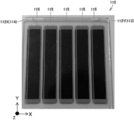
- FIG. 2 is a side cross-sectional view illustrating the entire configuration of the solar cell unit 100 according to the first embodiment. It is a photograph which shows the light-receiving surface side of the solar cell 110 of the solar cell unit 100 concerning 1st Embodiment.
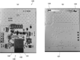
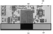
- 5A is a photograph showing the back surface of the substrate 120 according to the first embodiment
- FIG. 5B is a photograph showing the light receiving surface side of the substrate 120 of the solar cell unit 100 according to the first embodiment.
- FIG. 11 is a rear view showing a first glass substrate 111 and a second glass substrate 112 of a solar cell 110 according to a second embodiment. It is a side view showing the 1st glass substrate 111, the 2nd glass substrate 112, and substrate 120 of solar cell 110 concerning a 2nd embodiment.
- FIG. 11 is a rear view showing a first glass substrate 111 and a second glass substrate 112 of a solar cell 110 according to a second embodiment. It is a side view showing the 1st glass substrate 111, the 2nd glass substrate 112, and substrate 120 of solar cell 110 concerning a 2nd embodiment.
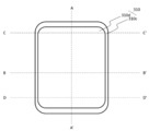
- FIG. 14 is a front view of a wireless transmitter 300 according to a fourth embodiment.
- FIG. 14 is a rear view of the wireless transmitter 300 according to the fourth embodiment.
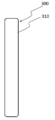
- FIG. 14 is a side view of a wireless transmitter 300 according to a fourth embodiment.
- FIG. 12 is a sectional view taken along line A-A ′ in FIG. 11.
- FIG. 12 is a sectional view taken along the line B-B ′ in FIG. 11.
- FIG. 12 is a sectional view taken along the line C-C ′ in FIG. 11.
- FIG. 12 is a sectional view taken along line D-D ′ in FIG. 11. It is B-B 'sectional drawing of the wireless transmitter 300 in 5th Embodiment.
- It is a front view of the radio transmitter 300 concerning a 6th embodiment.
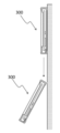
- radio transmitter 300 It is A-A 'sectional drawing of radio transmitter 300 in a 7th embodiment. It is an image figure showing a posture at the time of fall of radio transmitter 300 in a 7th embodiment. It is B-B 'sectional drawing of the wireless transmitter 300 in 9th Embodiment.
- solar cell unit 100 mainly includes solar cell 110, substrate 120, and communication module 130. Electronic components such as a capacitor for storing power generated by the solar cell 110 and a control IC may be further included.
- Solar cell 110 is mounted on the surface of substrate 120.
- the communication module 130 is mounted on the back surface of the board 120.
- the solar cell unit 100 performs various kinds of communication by the communication module 130 including the communication device 133 and the antenna 132 using the power generated by the solar cell 110.
- the communication module 130 including the communication device 133 and the antenna 132 using the power generated by the solar cell 110.
- the radio wave of the beacon can be periodically emitted while power is generated by light from indoor lights.
- a terminal such as a mobile phone that receives the radio wave of the beacon can accurately acquire its own position, or a server or the like can accurately acquire the position of the terminal.
- solar cell 110 includes first glass substrate 111 serving as a light receiving surface, and second glass substrate 112.
- a transparent conductive film is formed on the first glass substrate 111 on the second glass substrate 112 side.
- notches 112X and 112Y are formed at the end in the Y direction and the end in the X direction in FIG. 2 of the second glass substrate 112.
- the cutout portion 112Y of the transparent conductive film of the first glass substrate 111 becomes the negative output terminal 113 (first output terminal), and the cutout portion 112X becomes the positive output terminal 114 (second output terminal).
- the negative electrode output terminal 113 and the positive electrode output terminal 114 are formed on the back surface of the solar cell 110, that is, on the substrate 120 side.
- the material of the first glass substrate 111 is not particularly limited as long as it is a transparent substrate, and a film may be used instead of glass.
- the second glass substrate 112 can be replaced by a non-transparent substrate.
- the solar cell 110 is a monolithic dye-sensitized solar cell. As shown in FIG. 2, a plurality of vertically long cells 115, 115... Are arranged side by side in a lateral direction when viewed from the light receiving surface side of the solar cell 110. More specifically, solar cell 110 according to the present embodiment has a total output of 3 volts by connecting five cells 115 having an electromotive force of 0.6 volts in series.
- an area 210 for mounting the solar cell 110 is provided on the surface of the substrate 120, and a negative input terminal 123 is provided at a position facing the negative output terminal 113 of the solar cell 110.
- A first input terminal
- a positive input terminal 124 second input terminal
- a flat area 121 on which no electronic component or the like is mounted is formed on the opposite side away from the communication module 130.
- a portion on the back side of the area of the substrate 120 on the side of the negative pole input terminal 123 and the side of the positive pole input terminal 124, that is, the area away from the communication module 130 is formed flat.
- the flat area 121 includes an end portion of the substrate 120 and is preferably an integrated area of 1 / or more of the entire substrate 120.
- the distance from the end of the communication module 130 where the antenna 132 is arranged to the opposite end is Amm
- the distance from the opposite end to a position that is 1 / or more of Amm away from the opposite end It is preferable to keep it flat.
- the degree of flatness does not need to be flat to about 1 ⁇ m or about 1 nm, and if it is less than 1/10, more preferably less than 1/20 with respect to the size of the substrate 120, for example, Amm. Good.
- the substrate 120 can be stably held by placing the substrate 120 on the flat table 200 with the flat area 121 facing down, and Workability can be improved.
- the substrate 120 is placed on a flat table with the area being down. Accordingly, the substrate 120 can be stably held, and workability on the surface of the substrate 120 can be improved.
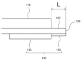
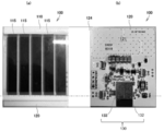
- the negative input terminal 123 and the positive input terminal 124 and the communication module 130 are arranged on the opposite sides of the substrate 120 with respect to the Y direction in FIG. As shown in FIGS. 5 to 8, the cells 115, 115... Of the solar cell 110 are closer to the minus pole input terminal 123 and the plus pole input terminal 124 with respect to the substrate 120. More specifically, the configuration is such that the cells 115 of the solar cell 110 do not extend to the antenna 132 of the communication module 130. In other words, the antenna 132 of the communication module 130 is configured such that the solar cell 110 is not stacked on the surface of the substrate 120 and is located on the non-conductive portion 127 of the substrate 120.
- the non-conductive portion 127 refers to a portion where the substrate 120 protrudes from the edge of the solar cell 110 by the shortest distance L as shown in FIG.
- a communication antenna 132 is provided on the back surface of the portion of the substrate 120 protruding from the edge of the solar cell 110. As shown in FIG. 8, it is preferable that no conductive material be disposed in the non-conductor portion 127 of the substrate 120 other than the communication antenna 132. This can reduce interference with the communication of the communication module 130 by the solar cell 110.
- the solar cell 110 and the communication module 130 are electrically connected to each other through a conductor (not shown) inside the substrate 120 provided from the negative pole input terminal 123 and the positive pole input terminal 124. That is, it is preferable that the conductive wires provided from the negative pole input terminal 123 and the positive pole input terminal 124 inside the substrate 120 are not exposed in the flat area 121 on the back surface of the substrate 120.
- the flat area 121 on the back surface of the substrate 120 may be formed of a resin covering the conductor.
- the communication module 130 has a rectangular shape, and the longitudinal direction of the antenna 132 of the communication module 130 is configured to be parallel to the edge of the substrate 120.
- the communication module 130 is mounted so that the antenna 132 does not protrude from the board 120 and fits inside the board 120. Therefore, it is possible to prevent the antenna 132 having low rigidity from being damaged.
- all or part of the antenna 132 may be configured so as to be parallel to the edge of the substrate 120 and along the edge of the substrate 120. That is, it is preferable that the long portion of the antenna 132 is arranged parallel to the edge of the substrate 120.
- the second glass substrate 112 may be cut not only at the notches 112X and 112Y but also at the entire end. That is, as shown in FIGS. 9 and 10, the first glass substrate 111 and the second glass substrate 112 are offset such that the edge of the second glass substrate 112 is inward of the edge of the first glass substrate 111. It may be stuck so that it does.
- the solar cell unit 100 after the first glass substrate 111 and the second glass substrate 112 are bonded together, the first glass substrate 111 and the first glass substrate Between the glass substrate 111 and the second glass substrate 112 is injected. Then, an ultraviolet curable resin 116 is applied to the back surface of the first glass substrate 111 and the side surface of the second glass substrate 112 so as to cover the inlet for the electrolyte. At this time, the ultraviolet curable resin 116 is not applied to the notches 112X and 112Y.
- the dye-sensitized solar cell 110 has been described, but another type of solar cell may be used.
- the communication module 130 is disposed at one end of the substrate 120 in the longitudinal direction of the cells 115 of the solar cell 110, and the cells 115, 115,.
- the negative input terminal 123 and the positive input terminal 124 are arranged at the other end in the longitudinal direction, but the communication module 130 is arranged at one short end of the cells 115 of the solar cell 110.
- the negative input terminal 123 and the positive input terminal 124 may be arranged at the other ends of the cells 115 of the battery 110 in the short direction.
- FIG. 11 is a front view of a wireless transmitter 300 according to the fourth embodiment.
- FIG. 12 is a rear view of the wireless transmitter 300 according to the fourth embodiment.
- FIG. 13 is a side view of the wireless transmitter 300 according to the fourth embodiment.
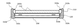
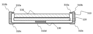
- FIG. 14 is a sectional view taken along the line A-A 'in FIG.
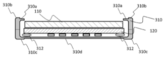
- FIG. 15 is a sectional view taken along the line B-B 'in FIG.
- FIG. 16 is a sectional view taken along the line C-C 'in FIG.
- FIG. 17 is a sectional view taken along the line D-D 'in FIG.
- the left side of the wireless transmitter 300 is referred to as the left side of the wireless transmitter 300
- the near side of the sheet of FIG. 11 is referred to as the front of the wireless transmitter 300
- the wireless transmitter 300 includes the solar cell unit 100 and a housing 310 that covers a part thereof.
- the solar cell 110 provided in the solar cell unit 100 is arranged so that external light can enter from outside the housing 310.
- the wireless transmitter 300 is provided with a fixture (not shown), and is used by being attached to a wall surface or a ceiling.
- case 310 is formed of an elastic member in order to reduce the impact that substrate 120 or solar cell 110 receives when falling from the wall surface on which wireless transmitter 100 is mounted.
- it is formed of a resin such as plastic or rubber.
- the radio transmitter 300 includes the housing 310, the substrate 120 on which the communication device 133 is mounted and the solar battery 110 held inside the housing 310, and the cells 115 and 115 of the solar battery 110. 115 are configured to easily receive external light without being covered by the housing 310.
- the housing 310 includes a front part 310a and a back part 310c.
- the front part 310a and the back part 310c are connected to each other by screws or the like.
- an opening 310x is formed in the front part 310a at a position where the solar cell 110 is located.
- the area of the opening 310x is smaller than the area of the substrate 120, but is preferably larger than the area of the solar cell 110.
- the area of the opening 310x may be smaller than the area of the solar cell 110 and larger than the area where the cells 115 are arranged.
- the substrate 120 and the substrate 120 side of the solar cell 110 are brought into contact with the back part 310c.
- the front part 310a and the back part 310c are closed in this state, the substrate 120 and the solar cell 110 are sandwiched between the front part 310a and the back part 310c.
- the left and right side surfaces of substrate 120 are sandwiched by left and right wall surfaces 310e, 310e inside housing 310.
- the substrate 120 when the substrate 120 is sandwiched between the housings 310 from the left and right directions, the substrate 120 is supported inside the housing 310 so as not to fall down. Note that in this state, it is preferable that other portions of the substrate 120, the solar cell 110, and the like do not contact the housing 310. Thus, even if the wireless transmitter 300 attached to a wall, a pillar, a ceiling, or the like falls, the possibility that the substrate 120 or the solar cell 110 hits the housing 300 and is damaged can be reduced.
- the left and right side surfaces of the substrate 120 are sandwiched by the left and right wall surfaces 310e, 310e inside the housing 300, the left and right side surfaces of the substrate 120 are applied by applying a force that does not damage the substrate 120. It is preferable to slide with respect to 310e. At this time, it is preferable that there is a space between the substrate 120 and the inner wall of the housing 310 in the vertical direction shown in FIG. 1 to allow the substrate 120 to slide.
- the left and right side surfaces of substrate 120 are sandwiched by left and right wall surfaces 310e, 310e inside case 310 so that the upper and lower side surfaces of substrate 120 are held at positions not in contact with case 310.
- a gap that is, a space is formed between a surface other than the left and right side surfaces of the substrate 120 and the inner wall surface of the housing 310.
- a configuration in which the upper and lower side surfaces of the substrate 120 are also sandwiched between inner wall surfaces of the housing 310 may be employed.
- one or more portions of the substrate 120 other than the above-described holding portion may directly or indirectly contact or be supported on the inner wall surface of the housing 310.
- the substrate 120 is held by the housing 310 with the front end of the solar cell 110 positioned behind the front end of the housing 310. That is, it is preferable that the solar cell 110 be held by the housing 310 in a state of being recessed inside the housing 310. This can reduce the possibility that the solar cell 110 contacts the floor surface even when the front surface side of the housing 310 contacts the floor surface or the like.
- the inside of the front part 310a of the housing 310 that is, the end 310b on the opening 310x side is recessed rearward.
- the edge of the housing 310 on the opening 310x side is formed in a convex shape toward the center of the opening 310x.
- the central part 310d in the front view or the rear view is formed to be thinner than the surrounding part in the front view or the rear view.
- the antenna 132 is located at a position close to the lower end (first end) of the substrate 120 in the vertical direction (second direction) intersecting at right angles to the horizontal direction (first direction) shown in FIG. It is preferred that When the length in the vertical direction (second direction) of the substrate 120 shown in FIG. 1 is W, the antenna 132 may be arranged in a range from the lower end (first end) of the substrate 120 to 1 / 3W or less. More preferably, it is more preferably arranged along the lower end (first end) of the substrate 120. Since the antenna 132 is located closer to the lower end (first end), the signal intensity of the signal transmitted by the antenna 132 is suppressed from being attenuated by the solar cell 110 attached to the surface of the substrate 120. .
- the position of the side surface of substrate 120 sandwiched between left and right side surfaces 310e, 310e of substrate 120 may be a position close to the upper end (second end) of substrate 120 as shown in FIG. preferable.
- the position of the side surface of the substrate 120 sandwiched between the left and right side surfaces of the substrate 120 is preferably located within a range of WW or less from the upper end (second end) of the substrate 120, and ⁇ ⁇ ⁇ W from the upper end. More preferably, it is located in the following range.
- an elastic member 312 softer than the material of the housing 310 may be provided between the substrate 120 and the housing 310 as shown in FIG. Thereby, when the wireless transmitter 300 falls, the impact which the board
- the elastic member 312 is not limited to the rear side of the substrate 120 and may be disposed between the lower surface, the upper surface, the side surface, or the like of the substrate 120 or the solar cell 110 and the inner wall surface of the housing 310.
- a wall-mounting member be attached to the upper end of the housing 310 as shown in FIG.
- the housing 310 can be easily attached to a wall or a pillar projection.
- case 310 preferably sandwiches substrate 120 and solar cell 110 such that antenna 132 side of substrate 120 is located below. That is, it is preferable that the wall surface attaching member 340 is attached to the end of the housing 310 that is farther from the antenna 132.
- a center-of-gravity adjusting unit 350 that is, a weight is attached to the back side inside the housing 310. More specifically, it is preferable that the weight of the center-of-gravity adjusting unit 350 is not less than 1/3 and not more than 3/2 of the total weight of the substrate 120 and the solar cell 110.
- the center-of-gravity adjustment unit 350 is not limited to the inside of the housing 310, and may be attached to the outside of the housing 310 near the rear surface.
- center-of-gravity adjusting unit 350 may be arranged on a part of the bottom surface of the housing 310, may be arranged widely on the entire bottom surface of the housing 310, or may be arranged around the bottom surface of the housing 310. May be done. ⁇ Eighth Embodiment>
- the case 310 is configured such that the front part 310a and the back part 310c can be bent together.
- the front part 310a and the back part 310c may be connected to each other such that the right part of the front part 310a and the left part of the back part 310c are rotatable, or the left part of the front part 310a may be connected to the front part 310a.
- the right part of the back part 310c may be rotatably connected, the upper part of the front part 310a and the upper part of the back part 310c may be rotatably connected, or the front part 310a And the lower part of the back part 310c may be rotatably connected.
- the front part 310a and the back part 310c may be bonded from the front.
- the front part 310a and the back part 310c may be detachably attached to each other, or may be fixed to each other with an adhesive or the like.
- the end 310 b of the housing 310 on the side of the opening 301 x may cover the edge of the solar cell 110. That is, the opening area of the opening 310x of the housing 310 is smaller than the substrate of the solar cell 110. With such a configuration, dust can be prevented from entering the housing 310 from the opening 310x.
Landscapes
- Engineering & Computer Science (AREA)
- Power Engineering (AREA)
- Microelectronics & Electronic Packaging (AREA)
- Chemical Kinetics & Catalysis (AREA)
- Electrochemistry (AREA)
- Chemical & Material Sciences (AREA)
- Computer Networks & Wireless Communication (AREA)
- Computer Hardware Design (AREA)
- Physics & Mathematics (AREA)
- General Physics & Mathematics (AREA)
- Theoretical Computer Science (AREA)
- Photovoltaic Devices (AREA)
- Details Of Aerials (AREA)
- Support Of Aerials (AREA)
Abstract
L'invention concerne une unité de batterie solaire (100) comprenant un substrat (120), une batterie solaire (110) fixée à la surface arrière du substrat (120), et un module de communication (130) fixé au substrat (120). Une antenne (132) du module de communication (130) est disposée de manière à ne pas chevaucher les cellules (115, 115...) de la batterie solaire (110) tel que visualisé depuis la surface avant.
Priority Applications (2)
| Application Number | Priority Date | Filing Date | Title |
|---|---|---|---|
| JP2020532247A JP6975859B2 (ja) | 2018-07-24 | 2019-07-01 | 太陽電池ユニットおよび太陽電池ユニットを備えた無線発信機 |
| US17/260,457 US11569044B2 (en) | 2018-07-24 | 2019-07-01 | Solar battery unit and wireless transmitter including solar battery unit |
Applications Claiming Priority (6)
| Application Number | Priority Date | Filing Date | Title |
|---|---|---|---|
| JP2018138848 | 2018-07-24 | ||
| JP2018138849 | 2018-07-24 | ||
| JP2018-138850 | 2018-07-24 | ||
| JP2018-138849 | 2018-07-24 | ||
| JP2018138850 | 2018-07-24 | ||
| JP2018-138848 | 2018-07-24 |
Publications (1)
| Publication Number | Publication Date |
|---|---|
| WO2020021982A1 true WO2020021982A1 (fr) | 2020-01-30 |
Family
ID=69181554
Family Applications (1)
| Application Number | Title | Priority Date | Filing Date |
|---|---|---|---|
| PCT/JP2019/026140 Ceased WO2020021982A1 (fr) | 2018-07-24 | 2019-07-01 | Unité de batterie solaire et émetteur sans fil comprenant une unité de batterie solaire |
Country Status (3)
| Country | Link |
|---|---|
| US (1) | US11569044B2 (fr) |
| JP (1) | JP6975859B2 (fr) |
| WO (1) | WO2020021982A1 (fr) |
Citations (5)
| Publication number | Priority date | Publication date | Assignee | Title |
|---|---|---|---|---|
| JP2006145558A (ja) * | 2003-05-09 | 2006-06-08 | Seiko Epson Corp | 無線通信機能付電子時計 |
| JP2011163913A (ja) * | 2010-02-09 | 2011-08-25 | Citizen Holdings Co Ltd | 電波時計 |
| JP2016167604A (ja) * | 2012-09-01 | 2016-09-15 | 株式会社フジクラ | 低照度用色素増感太陽電池素子 |
| JP2017037057A (ja) * | 2015-08-06 | 2017-02-16 | セイコーエプソン株式会社 | 電子時計 |
| JP2017098358A (ja) * | 2015-11-20 | 2017-06-01 | 株式会社フジクラ | 光電変換素子 |
Family Cites Families (7)
| Publication number | Priority date | Publication date | Assignee | Title |
|---|---|---|---|---|
| CN100487606C (zh) | 2003-05-09 | 2009-05-13 | 精工爱普生株式会社 | 具有无线通信功能的电子钟表 |
| US20080013409A1 (en) * | 2006-07-11 | 2008-01-17 | Bland Diarmuid John St Cullom | Timepiece with overlapping, separately driven analog and mechanical functionality |
| WO2010113708A1 (fr) * | 2009-03-30 | 2010-10-07 | 三菱マテリアル株式会社 | Procédé de production d'un module de pile solaire |
| US9147794B2 (en) * | 2011-11-30 | 2015-09-29 | First Solar, Inc. | Three terminal thin film photovoltaic module and their methods of manufacture |
| WO2014034913A1 (fr) | 2012-09-01 | 2014-03-06 | 株式会社フジクラ | Élément de cellule solaire à pigment photosensible pour faible luminance |
| JP2014160957A (ja) | 2013-02-20 | 2014-09-04 | Murata Mfg Co Ltd | アンテナ装置 |
| JP6907940B2 (ja) | 2015-07-21 | 2021-07-21 | ソニーグループ株式会社 | 通信装置 |
-
2019
- 2019-07-01 US US17/260,457 patent/US11569044B2/en active Active
- 2019-07-01 JP JP2020532247A patent/JP6975859B2/ja not_active Expired - Fee Related
- 2019-07-01 WO PCT/JP2019/026140 patent/WO2020021982A1/fr not_active Ceased
Patent Citations (5)
| Publication number | Priority date | Publication date | Assignee | Title |
|---|---|---|---|---|
| JP2006145558A (ja) * | 2003-05-09 | 2006-06-08 | Seiko Epson Corp | 無線通信機能付電子時計 |
| JP2011163913A (ja) * | 2010-02-09 | 2011-08-25 | Citizen Holdings Co Ltd | 電波時計 |
| JP2016167604A (ja) * | 2012-09-01 | 2016-09-15 | 株式会社フジクラ | 低照度用色素増感太陽電池素子 |
| JP2017037057A (ja) * | 2015-08-06 | 2017-02-16 | セイコーエプソン株式会社 | 電子時計 |
| JP2017098358A (ja) * | 2015-11-20 | 2017-06-01 | 株式会社フジクラ | 光電変換素子 |
Also Published As
| Publication number | Publication date |
|---|---|
| JP6975859B2 (ja) | 2021-12-01 |
| US20210304971A1 (en) | 2021-09-30 |
| JPWO2020021982A1 (ja) | 2021-08-19 |
| US11569044B2 (en) | 2023-01-31 |
Similar Documents
| Publication | Publication Date | Title |
|---|---|---|
| JP6995862B2 (ja) | カメラモジュールおよびモバイル端末 | |
| EP3832993B1 (fr) | Appareil électronique portable | |
| EP3832797B1 (fr) | Appareil électronique portable | |
| US20210168231A1 (en) | Handheld electronic device | |
| US10516814B2 (en) | Camera assembly and electronic device | |
| US7957123B2 (en) | Portable electronic device | |
| US7744296B2 (en) | Camera module having colloid layer surrounding sensor | |
| US20140255016A1 (en) | Device for driving camera lens module in portable terminal | |
| CN207968641U (zh) | 摄像头模块 | |
| CN101285919A (zh) | 相机模组 | |
| US11463039B2 (en) | Energy harvester | |
| WO2019052332A1 (fr) | Ensemble écran d'affichage et terminal mobile | |
| TWI672552B (zh) | 鏡頭模組 | |
| JP2010041709A (ja) | カメラモジュール | |
| JP2007128995A (ja) | 撮像素子のfpcに対する取り付け構造 | |
| JP2015144412A (ja) | 電子機器 | |
| CN108924402B (zh) | 摄像模组及终端设备 | |
| CN113489890B (zh) | 拍摄装置以及电子设备 | |
| US8901784B2 (en) | Voice coil motor with spacer | |
| JP6975859B2 (ja) | 太陽電池ユニットおよび太陽電池ユニットを備えた無線発信機 | |
| CN115811718A (zh) | 一种控制器 | |
| JP6764937B2 (ja) | 部品の取付構造および端末 | |
| JP4657610B2 (ja) | 携帯端末装置 | |
| JP4260646B2 (ja) | 携帯端末装置 | |
| CN121152148A (zh) | 电子设备、壳体组件和中框 |
Legal Events
| Date | Code | Title | Description |
|---|---|---|---|
| 121 | Ep: the epo has been informed by wipo that ep was designated in this application |
Ref document number: 19842083 Country of ref document: EP Kind code of ref document: A1 |
|
| ENP | Entry into the national phase |
Ref document number: 2020532247 Country of ref document: JP Kind code of ref document: A |
|
| NENP | Non-entry into the national phase |
Ref country code: DE |
|
| 122 | Ep: pct application non-entry in european phase |
Ref document number: 19842083 Country of ref document: EP Kind code of ref document: A1 |