WO2020026625A1 - ゴルフクラブ用グリップおよびゴルフクラブ - Google Patents
ゴルフクラブ用グリップおよびゴルフクラブ Download PDFInfo
- Publication number
- WO2020026625A1 WO2020026625A1 PCT/JP2019/024227 JP2019024227W WO2020026625A1 WO 2020026625 A1 WO2020026625 A1 WO 2020026625A1 JP 2019024227 W JP2019024227 W JP 2019024227W WO 2020026625 A1 WO2020026625 A1 WO 2020026625A1
- Authority
- WO
- WIPO (PCT)
- Prior art keywords
- grip
- narrow groove
- golf club
- rubber
- narrow
- Prior art date
- Legal status (The legal status is an assumption and is not a legal conclusion. Google has not performed a legal analysis and makes no representation as to the accuracy of the status listed.)
- Ceased
Links
Images






Classifications
-
- A—HUMAN NECESSITIES
- A63—SPORTS; GAMES; AMUSEMENTS
- A63B—APPARATUS FOR PHYSICAL TRAINING, GYMNASTICS, SWIMMING, CLIMBING, OR FENCING; BALL GAMES; TRAINING EQUIPMENT
- A63B60/00—Details or accessories of golf clubs, bats, rackets or the like
- A63B60/06—Handles
- A63B60/14—Coverings specially adapted for handles, e.g. sleeves or ribbons
-
- A—HUMAN NECESSITIES
- A63—SPORTS; GAMES; AMUSEMENTS
- A63B—APPARATUS FOR PHYSICAL TRAINING, GYMNASTICS, SWIMMING, CLIMBING, OR FENCING; BALL GAMES; TRAINING EQUIPMENT
- A63B53/00—Golf clubs
- A63B53/14—Handles
-
- A—HUMAN NECESSITIES
- A63—SPORTS; GAMES; AMUSEMENTS
- A63B—APPARATUS FOR PHYSICAL TRAINING, GYMNASTICS, SWIMMING, CLIMBING, OR FENCING; BALL GAMES; TRAINING EQUIPMENT
- A63B60/00—Details or accessories of golf clubs, bats, rackets or the like
- A63B60/06—Handles
-
- A—HUMAN NECESSITIES
- A63—SPORTS; GAMES; AMUSEMENTS
- A63B—APPARATUS FOR PHYSICAL TRAINING, GYMNASTICS, SWIMMING, CLIMBING, OR FENCING; BALL GAMES; TRAINING EQUIPMENT
- A63B60/00—Details or accessories of golf clubs, bats, rackets or the like
- A63B60/06—Handles
- A63B60/08—Handles characterised by the material
-
- A—HUMAN NECESSITIES
- A63—SPORTS; GAMES; AMUSEMENTS
- A63B—APPARATUS FOR PHYSICAL TRAINING, GYMNASTICS, SWIMMING, CLIMBING, OR FENCING; BALL GAMES; TRAINING EQUIPMENT
- A63B60/00—Details or accessories of golf clubs, bats, rackets or the like
- A63B60/06—Handles
- A63B60/18—Handles with means for cooling, ventilating or sweat-reduction, e.g. holes or powder dispensers
-
- A—HUMAN NECESSITIES
- A63—SPORTS; GAMES; AMUSEMENTS
- A63B—APPARATUS FOR PHYSICAL TRAINING, GYMNASTICS, SWIMMING, CLIMBING, OR FENCING; BALL GAMES; TRAINING EQUIPMENT
- A63B2209/00—Characteristics of used materials
-
- A—HUMAN NECESSITIES
- A63—SPORTS; GAMES; AMUSEMENTS
- A63B—APPARATUS FOR PHYSICAL TRAINING, GYMNASTICS, SWIMMING, CLIMBING, OR FENCING; BALL GAMES; TRAINING EQUIPMENT
- A63B2209/00—Characteristics of used materials
- A63B2209/02—Characteristics of used materials with reinforcing fibres, e.g. carbon, polyamide fibres
Definitions
- the present invention relates to a golf club grip.
- the golf club includes a shaft, a head mounted near the front end of the shaft, and a grip inserted near the rear end of the shaft.
- the grip is a part that a golfer swinging the golf club grasps by hand, and plays a very important role when the movement of the golfer is transmitted to the golf club.
- An important required performance of the grip is that slippage between a golfer's hand and the grip during a swing is suppressed.
- the grip is formed of a flexible material such as rubber or synthetic resin, and a groove or dent pattern is formed on its surface to further enhance the anti-slip performance (for example, see Patent Document 1 (paragraph 0035, paragraph 0035, See FIG. 4).
- Patent Document 2 proposes a grip in which a stem array having individual zones of stems having different heights is formed on a grip surface (see Patent Document 2 (paragraphs 0040 to 0043)).
- a stem having a height of about 0.020 to about 0.030 inches (0.508 to 0.762 mm) is formed in the first zone.
- Patent Document 2 proposes providing fine protrusions on the grip surface in order to enhance the slip resistance of the grip.
- the shape of the projection is made fine, it is necessary to reduce the depth of the groove between the projections in order to maintain the strength of the projection. For this reason, moisture such as sweat and rain of the golfer tends to stay on the fine protrusions, and the dryness of the grip surface tends to decrease.
- the present invention has been made in view of the above circumstances, and an object of the present invention is to provide a golf club grip excellent in anti-slip performance and feeling when wet.
- the golf club grip of the present invention that can solve the above problem has a cylindrical portion into which a shaft is inserted, and at least a part of the surface of the cylindrical portion has an occupation ratio of a narrow groove per 25 mm 2.
- the grip has a narrow groove region in which a fixed amount of narrow grooves having a specific width and a specific depth are formed.
- moisture such as a sweat or rain of a golfer can be taken into the narrow groove, and the grip surface can be kept in a dry state.
- an anti-slip performance is improved by an island portion appearing as a result of being partitioned by the narrow groove catching on a user's skin.
- the present invention also includes a golf club including a shaft, a head attached to one end of the shaft, and a grip attached to the other end of the shaft, wherein the grip is the golf club grip.
- a golf club grip excellent in anti-slip performance and feeling when wet can be obtained.
- FIG. 2 is a sectional view taken along line AA of a narrow groove region in FIG. 1.
- FIG. 2 is a sectional view taken along line BB of a narrow groove region in FIG. 1.
- FIG. 5 is a sectional view taken along line AA of the narrow groove region of FIG. 4.
- FIG. 5 is a BB cross-sectional view of the narrow groove region of FIG. 4.
- FIG. 9 is a schematic cross-sectional view taken along the line CC of the golf club grip of FIG. 8. It is a perspective view showing an example of a golf club.
- the golf club grip of the present invention has a cylindrical portion into which a shaft is inserted, and a narrow groove region in which the occupation ratio of the narrow groove per 25 mm 2 is 35% or more on at least a part of the surface of the cylindrical portion. Having.
- the grip has a narrow groove region in which a fixed amount of a narrow groove having a specific width and a specific depth is formed. In the narrow groove region, moisture such as a sweat or rain of a golfer can be taken into the narrow groove, and the grip surface can be kept in a dry state. Further, in the grip, an anti-slip performance is improved by an island portion appearing as a result of being partitioned by the narrow groove catching on a user's skin.
- the narrow groove region is a region formed so that a specific narrow groove has a constant occupancy.
- the occupation ratio of the narrow groove in the narrow groove region is 35% or more, preferably 38% or more, more preferably 40% or more, and preferably 65% or less, more preferably 60% or less per 25 mm 2 (5 mm ⁇ 5 mm square). %, More preferably 55% or less.
- the occupation ratio of the narrow groove is 35% or more, water does not easily overflow from the narrow groove, and the feeling when wet is improved. If the occupation ratio of the narrow groove is 65% or less, no slip due to a decrease in the contact area is felt, and the anti-slip performance is improved.
- the occupancy is the ratio of the area of the narrow groove per unit area.
- the area of the narrow groove may be measured by observing the surface of the grip with a microscope, or may be calculated from the width (w) of the narrow groove on the grip surface, the length of the narrow groove, and the number of the narrow grooves. Good. In the narrow groove region, a groove other than the narrow groove described later may be formed, but when calculating the area, only the area of the narrow groove is measured.
- the narrow groove formed in the narrow groove region has a width (w) of 0.1 mm to 0.7 mm.
- the width of the narrow groove is preferably 0.2 mm or more, more preferably 0.3 mm or more, preferably 0.6 mm or less, more preferably 0.5 mm or less.
- the width of the narrow groove measures the width at the surface of the grip. The measurement may be performed using a micrometer or the like.
- the depth (h) of the narrow groove is 0.1 mm to 1.0 mm. When the depth of the narrow groove is within this range, it becomes easy to take in moisture such as sweat of a golfer into the inside of the narrow groove.
- the depth of the narrow groove is preferably 0.2 mm or more, more preferably 0.3 mm or more, preferably 0.8 mm or less, more preferably 0.7 mm or less.
- the width of the groove may be constant in the depth direction, or the width at the grip surface and the width at the deepest portion may be different. The width of the groove may be formed so as to become narrower as the groove becomes deeper, or may be formed so as to be gradually reduced.
- the ratio (wd / ws) of the width (ws) of the narrow groove on the grip surface to the width (wd) at the deepest part of the narrow groove is preferably 1.0 or less, more preferably 0.8 or less, and still more preferably. Is 0.6 or less.
- Examples of the cross-sectional shape of the groove include a V-shape, a substantially V-shape, and a U-shape.
- a plurality of narrow grooves of one type may be formed, or a plurality of narrow grooves may be formed in combination.
- the shape of the narrow groove is not particularly limited, such as a linear shape or a curved shape, but is preferably a linear shape. Further, it is preferable that the width and the depth of the narrow groove are constant.
- the average length of the narrow groove is preferably 10 mm or more, more preferably 20 mm or more, and further preferably 30 mm or more.
- the average length of the narrow groove is 10 mm or more, the moisture taken in the narrow groove can be diffused in the narrow groove, and it becomes easier to take in moisture such as sweat of a golfer into the narrow groove.
- the distance (d) between the narrow grooves is preferably 1.5 mm or less, more preferably 1.2 mm or less, and further preferably 1.0 mm or less.
- the interval between the narrow grooves is 1.5 mm or less, the island portions formed between the narrow grooves are easily caught on the skin, and the feeling is further improved. As a result, the user's grip on the grip is unconsciously weakened, and the body's resistance to the swing is reduced, thereby improving the head speed.
- the interval between the narrow grooves is preferably 0.3 mm or more, more preferably 0.4 mm or more, and further preferably 0.5 mm or more.
- the interval between the narrow grooves is 0.3 mm or more, the mechanical strength of the island formed between the narrow grooves is increased, and the durability is further improved.
- the interval between the narrow grooves may be constant or may be different.
- the ratio (d / w) of the interval (d) between the narrow grooves and the width (w) of the narrow grooves is preferably 1 or more, more preferably 1.5 or more, further preferably 2 or more, and 5 The following is preferable, More preferably, it is 4.5 or less, More preferably, it is 4 or less. If the ratio (d / w) is within the above range, the feeling at the time of impact becomes better.
- the narrow groove is formed so as to intersect with another narrow groove. Since the narrow grooves intersect, sweat or rain taken in the narrow grooves can diffuse into other narrow grooves, and the grip surface can be kept in a dry state.
- the grip surface is divided by a narrow groove to form an island portion. The anti-slip performance is improved by the island portion appearing by being separated by the narrow groove catching on the user's skin.
- the fine grooves include a first fine groove group formed in parallel with each other, and a second fine groove group formed to intersect with the first fine groove group and formed in parallel with each other. It is preferable to have By forming the first narrow groove group and the second narrow groove group, it is easy to control the occupancy of the narrow groove.
- the angle between them is preferably 45 ° or more, more preferably 60 ° or more, even more preferably 80 ° or more, and 135 °.
- the following is preferable, More preferably, it is 120 degrees or less, More preferably, it is 100 degrees or less.
- the narrow groove region is provided in at least a part of a range of 10% to 100% of the cylindrical portion when the tip side end of the cylindrical portion is 0% and the butt side end is 100%. Is more preferable, more preferably in the range of 15% to 80%, and still more preferably in the range of 20% to 70%.
- the narrow groove region is formed in a range of 10% to 60% of the cylindrical portion.
- the area ratio of the narrow groove region is preferably at least 30 area%, more preferably at least 40 area%, further preferably at least 50 area%, It is preferably at most 95 area%, more preferably at most 90 area%, even more preferably at most 85 area%.
- the range in which the axial distance from the tip side end portion is 10% to 60% of the entire length is a portion where the user grips the grip with bare hands.
- the narrow groove region is formed so as to be continuous in the circumferential direction of the cylindrical portion.
- continuous in the circumferential direction includes not only a form that is linearly continuous in the circumferential direction but also a form that is continuous in a V-shape or U-shape in the circumferential direction.
- the circumferential length of the narrow groove region is preferably 10% or more, more preferably 20% or more, still more preferably 30% or more, and 100% or less of the circumferential length of the cylindrical portion.
- the narrow groove region may be formed at only one place or may be formed at a plurality of places.
- the total area of the narrow groove region is preferably 1400 mm 2 or more, more preferably 2800 mm 2 or more, and still more preferably 4200 mm 2 or more. When the total area is 1400 mm 2 or more, the feeling becomes better and the head speed is improved.
- the area of each narrow groove region is preferably 180 mm 2 or more, more preferably 360 mm 2 or more, and further preferably 540 mm 2 or more.
- the narrow groove region can be formed by laser processing or transfer from a mold, and is preferably formed by laser processing. By forming by laser processing, a narrow groove can be easily formed.
- FIG. 1 is a plan view showing an example of the narrow groove region.
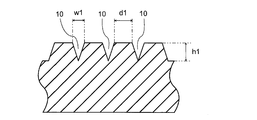
- FIG. 2 is a sectional view taken along line AA of the narrow groove region of FIG.
- FIG. 3 is a BB cross-sectional view of the narrow groove region of FIG.
- FIG. 4 is a plan view showing another example of the narrow groove region.
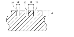
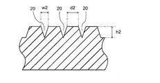
- FIG. 5 is a sectional view taken along line AA of the narrow groove region of FIG.
- FIG. 6 is a BB cross-sectional view of the narrow groove region of FIG.
- FIG. 7 is a plan view showing another example of the narrow groove region.
- a first narrow groove group 10 and a second narrow groove group 20 are formed in the narrow groove regions of FIGS.
- the width W1 and the interval d1 of the first narrow groove group 10 are formed to be constant.
- the width W2 and the interval d2 of the second narrow groove group 20 are formed to be constant. 1, 4 and 7, the width w1 of the first fine groove group 10 and the width w2 of the second fine groove group 20 are the same, and the distance d1 between the first fine groove groups 10 is small.
- the interval d2 between the second narrow groove group 20 and the second narrow groove group 20 are the same.
- the plan view shape of the island formed by the narrow groove is a square.
- the width w1 of the first narrow groove group 10 and the width w2 of the second narrow groove group 20 are formed to be constant in the depth direction. Therefore, the cross-sectional shape of the island formed by the narrow groove is a quadrangular prism.
- the width w1 of the first narrow groove group 10 and the width w2 of the second narrow groove group 20 are formed so as to become narrower as they become deeper. Therefore, the cross-sectional shape of the island formed by the narrow groove is a truncated quadrangular pyramid.
- FIG. 7 shows that, in the narrow groove region, when the direction of the first narrow groove group 10 is X and the direction of the second narrow groove group 20 is Y, the first narrow groove group 10 and the second narrow groove group 20 are different. Is 45 °. Therefore, the planar shape of the island portion formed by the narrow groove is a rhombus.
- the cylindrical portion of the golf club grip may have a single-layer structure or a multilayer structure.
- the narrow groove region and a region other than the narrow groove region may be formed from different compositions. Alternatively, they may be formed from the same composition.
- the narrow groove region and the other region are all solid layers.
- the cylindrical portion has the outermost layer and at least one inner layer.
- the outermost layer has a narrow groove region.
- the outermost layer is the outermost layer of the grip, and is the portion that the user touches when using the grip.
- the narrow groove region and the other region may be formed from different compositions, or may be formed from the same composition.
- the narrow groove region and the other region are preferably solid layers. It is preferable that at least one of the inner layers is a porous layer.
- a two-layer structure having the outermost layer and one inner layer; a three-layer structure having the outermost layer and two inner layers are preferable.
- the thickness of the cylindrical portion is preferably 0.5 mm or more, more preferably 1.0 mm or more, still more preferably 1.5 mm or more, preferably 17.0 mm or less, more preferably 10.0 mm or less, and still more preferably. Is 8.0 mm or less.
- the thickness of the cylindrical portion may be formed so as to be constant in the axial direction, or may be formed so as to gradually increase from the front end portion to the rear end portion.
- the thickness of the outermost layer is preferably 0.5 mm or more, more preferably 0.6 mm or more, and still more preferably 0.7 mm or more; It is preferably at most 2.5 mm, more preferably at most 2.3 mm, even more preferably at most 2.1 mm. If the thickness of the outer layer is 0.5 mm or more, the reinforcing effect of the outer layer material is greater, and if it is 2.5 mm or less, the inner layer can be relatively thicker, and the effect of reducing the weight of the grip increases. .
- the percentage of the thickness of the outermost layer with respect to the thickness of the cylindrical portion is preferably 0.5% or more, more preferably 1.0% or more, and still more preferably. Is 1.5% or more, preferably 99.0% or less, more preferably 98.0% or less, and still more preferably 97.0% or less.
- the percentage is 0.5% or more, the reinforcing effect of the outer layer material is further increased, and when it is 99.0% or less, the inner layer can be relatively thickened, and the effect of reducing the weight of the grip increases.
- the material of the cylindrical portion is not particularly limited, and can be formed from a rubber composition or a resin composition conventionally used for a golf club grip.
- the narrow groove region is formed from a rubber composition.
- the rubber composition (hereinafter, sometimes referred to as "first rubber composition") constituting the narrow groove region contains a base rubber and a crosslinking agent.
- NR natural rubber
- EPDM ethylene-propylene-diene rubber
- IIR butyl rubber
- HNBR hydrogenated acrylonitrile-butadiene rubber
- XNBR carboxy-modified acrylonitrile-butadiene Rubber
- HXNBR carboxy-modified hydrogenated acrylonitrile-butadiene rubber
- SBR polyurethane rubber
- PU isoprene rubber
- IR isoprene rubber
- CR chloroprene rubber
- EPM ethylene -Propylene rubber
- the base rubber preferably contains a non-polar rubber. If the base rubber contains the non-polar rubber, the grip can absorb the oil even when the sebum of the user adheres to the grip. Therefore, it is possible to suppress a decrease in anti-slip performance due to sebum of the user.
- the content of the nonpolar rubber in the base rubber is preferably 50% by mass or more, more preferably 60% by mass or more, and further preferably 70% by mass or more.
- the non-polar rubber has an SP (solubility parameter) value of 7.7 or more and less than 8.7.
- non-polar rubber examples include diene rubbers such as isoprene rubber (IR), butadiene rubber (BR), styrene-butadiene rubber (SBR), chloroprene rubber (CR), and natural rubber (NR); ethylene-propylene Non-diene rubbers such as rubber (EPM), ethylene-propylene-diene rubber (EPDM), and butyl rubber (IIR).
- diene rubbers such as isoprene rubber (IR), butadiene rubber (BR), styrene-butadiene rubber (SBR), chloroprene rubber (CR), and natural rubber (NR); ethylene-propylene Non-diene rubbers such as rubber (EPM), ethylene-propylene-diene rubber (EPDM), and butyl rubber (IIR).
- Non-polar rubbers may be used alone or in combination of two or more.
- a diene rubber is preferable, and the content of the diene rubber in the nonpolar rubber is preferably 50% by mass or
- the first rubber composition preferably contains a natural rubber as a base rubber.
- a natural rubber By containing natural rubber, the flexibility of the island portion is maintained even under cold conditions, and high anti-slip performance can be maintained.
- the content of the natural rubber in the base rubber is preferably 50% by mass or more, more preferably 55% by mass or more, and further preferably 60% by mass or more.
- a sulfur-based crosslinking agent and an organic peroxide can be used.
- the sulfur crosslinking agent include elemental sulfur and a sulfur donor type compound.
- the elemental sulfur include powdered sulfur, precipitated sulfur, colloidal sulfur, and insoluble sulfur.
- the sulfur donor type compound include 4,4'-dithiobismorpholine.
- organic peroxide examples include dicumyl peroxide, ⁇ , ⁇ ′-bis (t-butylperoxy-m-diisopropyl) benzene, 2,5-dimethyl-2,5-di (t-butylperoxy) Hexane, 1,1-bis (t-butylperoxy) 3,3,5-trimethylcyclohexane and the like can be mentioned.
- the crosslinking agents may be used alone or in combination of two or more.
- a sulfur-based crosslinking agent is preferred, and elemental sulfur is more preferred.
- the amount of the crosslinking agent to be used is preferably 0.2 parts by mass or more, more preferably 0.4 parts by mass or more, and still more preferably 0.6 parts by mass or more, based on 100 parts by mass of the base rubber. It is preferably at most 3.0 parts by mass, more preferably at most 3.5 parts by mass, even more preferably at most 3.0 parts by mass.
- the first rubber composition preferably further contains a vulcanization accelerator and a vulcanization activator.
- vulcanization accelerator examples include thiurams such as tetramethylthiuram disulfide (TMTD), tetrabenzylthiuram disulfide (TBzTD), tetramethylthiuram monosulfide (TMTM), dipentamethylenethiuram tetrasulfide; diphenylguanidine (DPG) and the like.
- TMTD tetramethylthiuram disulfide
- TBzTD tetrabenzylthiuram disulfide
- TMTM tetramethylthiuram monosulfide
- DPG diphenylguanidine
- Guanidine type dithiocarbamate type such as zinc dimethyldithiocarbamate (ZnPDC) and zinc dibutyldithiocarbamate; thiourea type such as trimethylthiourea and N, N'-diethylthiourea; mercaptobenzothiazole (MBT), benzothiazole disulfide and the like N-cyclohexyl-2-benzothiazolylsulfenamide (CBS), Nt-butyl-2-benzothiazolylsulfenamide (BBS) Any sulfenamide type; These vulcanization accelerators may be used alone or in combination of two or more.
- the total amount of the vulcanization accelerator is preferably at least 0.4 part by mass, more preferably at least 0.8 part by mass, and still more preferably at least 1.2 parts by mass, based on 100 parts by mass of the base rubber.
- the amount is preferably 8.0 parts by mass or less, more preferably 7.0 parts by mass or less, and still more preferably 6.0 parts by mass or less.
- Examples of the vulcanization activator include metal oxides (excluding titanium oxide), metal peroxides, and fatty acids.
- the metal oxide include zinc oxide, magnesium oxide, and lead oxide.
- Examples of the metal peroxide include zinc peroxide, chromium peroxide, magnesium peroxide, and calcium peroxide.
- Examples of the fatty acid include stearic acid, oleic acid, and palmitic acid. These vulcanization activators may be used alone or in combination of two or more.
- the total amount of the vulcanization activator is preferably at least 0.5 part by mass, more preferably at least 0.6 part by mass, further preferably at least 0.7 part by mass, based on 100 parts by mass of the base rubber.
- the content is preferably 10.0 parts by mass or less, more preferably 9.5 parts by mass or less, and still more preferably 9.0 parts by mass or less.
- the first rubber composition may further contain an antioxidant, a softener, a coloring agent, an anti-scorch agent, a resin, and the like, if necessary.
- Examples of the anti-aging agent include imidazoles, amines, phenols, thioureas and the like.
- Examples of the imidazoles include nickel dibutyldithiocarbamate (NDIBC), 2-mercaptobenzimidazole, and zinc salt of 2-mercaptobenzimidazole.
- Examples of amines include phenyl- ⁇ -naphthylamine.
- Examples of phenols include 2,2'-methylenebis (4-methyl-6-t-butylphenol) (MBMBP) and 2,6-di-tert-butyl-4-methylphenol.
- thioureas examples include tributylthiourea, 1,3-bis (dimethylaminopropyl) -2-thiourea, and the like. These antioxidants may be used alone or in combination of two or more. The amount of the antioxidant used is preferably 0.2 parts by mass or more, more preferably 0.3 parts by mass or more, and still more preferably 0.4 parts by mass or more, based on 100 parts by mass of the base rubber. It is preferably at most 5.0 parts by mass, more preferably at most 4.8 parts by mass, even more preferably at most 4.6 parts by mass.
- Examples of the softener include mineral oil and plasticizer.
- Examples of the mineral oil include paraffin oil, naphthenic oil, and aromatic oil.
- Examples of the plasticizer include dioctyl phthalate, dibutyl phthalate, dioctyl sepate, dioctyl adipate, and the like.
- Examples of the anti-scorch agent include organic acids and nitroso compounds.
- Examples of the organic acid include phthalic anhydride, pyromellitic anhydride, trimellitic anhydride, benzoic acid, salicylic acid, malic acid and the like.
- Examples of the nitroso compound include N-nitroso diphenylamine, N- (cyclohexylthio) phthalimide, a sulfonamide derivative, diphenylurea, bis (tridecyl) pentaerythritol diphosphite, and 2-mercaptobenzimidazole.
- the resin examples include a hydrogenated rosin ester, a disproportionated rosin ester, an ethylene-vinyl acetate copolymer, a coumarone resin, a phenol resin, a xylene resin, and a styrene resin.
- the first rubber composition can be prepared by a conventionally known method.
- it can be prepared by kneading each raw material using a kneading machine such as a Banbury mixer, a kneader, or an open roll.
- the material hardness (Shore A hardness) of the first rubber composition is preferably 40 or more, more preferably 42 or more, even more preferably 45 or more, preferably 60 or less, more preferably 58 or less, and still more preferably 55 or less. It is as follows. If the material hardness (Shore A hardness) of the first rubber composition is 40 or more, the mechanical strength of the narrow groove region is further improved, and if it is 60 or less, the outermost layer is not too hard, and the grip feeling when gripping is obtained. Is better.
- the material other than the narrow groove region is not particularly limited, but is preferably formed from the first rubber composition.
- the rubber composition constituting the other region may have the same composition as the rubber composition constituting the narrow groove region, or may have a different composition. If these have the same composition, the production of the cylindrical portion or the outermost layer becomes easy.
- the material of the inner layer is not particularly limited.
- the composition for forming the inner layer include a second rubber composition and a resin composition.
- the second rubber composition preferably contains a base rubber and a crosslinking agent.
- a base rubber natural rubber (NR), ethylene-propylene-diene rubber (EPDM), butyl rubber (IIR), acrylonitrile-butadiene rubber (NBR), hydrogenated acrylonitrile-butadiene rubber (HNBR), carboxy-modified acrylonitrile-butadiene Rubber (XNBR), carboxy-modified hydrogenated acrylonitrile-butadiene rubber (HXNBR), butadiene rubber (BR), styrene-butadiene rubber (SBR), polyurethane rubber (PU), isoprene rubber (IR), chloroprene rubber (CR), ethylene -Propylene rubber (EPM) and the like.
- NR, EPDM, IIR, NBR, HNBR, XNBR, HXNBR, BR, SBR, and PU are preferable as the base rubber.
- the cross-linking agent for the second rubber composition the same one as used in the first rubber composition may be mentioned, and simple sulfur is preferable. It is preferable that the second rubber composition further contains a vulcanization accelerator and a vulcanization activator.
- the same vulcanization accelerator and vulcanization activator as those used in the first rubber composition can be used.
- As the vulcanization accelerator Nt-butyl-2-benzothiazolylsulfenamide and tetrabenzylthiuram disulfide are preferable.
- As the vulcanization activator zinc oxide and stearic acid are preferable.
- the second rubber composition may further contain a reinforcing material, an antioxidant, a softener, a coloring agent, an anti-scorch agent, and the like, if necessary.
- a reinforcing material examples include the same as those used in the first rubber composition.
- the reinforcing material carbon black and silica are preferable.
- the antioxidant 2,2'-methylenebis (4-methyl-6-t-butylphenol) is preferable.
- the second rubber composition can be prepared by a conventionally known method. For example, it can be prepared by kneading each raw material using a kneading machine such as a Banbury mixer, a kneader, or an open roll.
- the temperature (material temperature) for kneading is preferably from 70 ° C to 160 ° C.
- the second rubber composition contains microballoons, it is preferable to knead the mixture at a temperature lower than the expansion start temperature of the microballoons.
- the resin composition contains a base resin.
- the base resin include polyurethane resin, polystyrene resin, polyethylene resin, polypropylene resin, ethylene-vinyl acetate copolymer resin, and polyethylene terephthalate resin.
- a second rubber composition is preferable, and it is preferable that the second composition contains a natural rubber (NR), an ethylene-propylene-diene rubber (EPDM), and a butyl rubber (IIR) as a base rubber.
- NR natural rubber
- EPDM ethylene-propylene-diene rubber
- IIR butyl rubber
- the composition forming the other part contains natural rubber (NR), ethylene-propylene-diene rubber (EPDM), and butyl rubber (IIR), the part formed from the first rubber composition and the other part The adhesion is improved.
- the inner layer may be a solid layer or a porous layer. If the inner layer is a porous layer, the weight of the golf club grip can be reduced.
- the porous layer is a layer in which a large number of pores (voids) are formed in rubber as a base material. By forming a large number of pores, the apparent density of the layer is reduced and the weight can be reduced.
- a balloon foaming method As a method for producing the porous layer, a balloon foaming method, a chemical foaming method, a supercritical carbon dioxide injection molding method, a salt extraction method, a solvent removing method and the like can be mentioned.
- the rubber composition contains microballoons, and the microballoons are expanded by heating and foamed.
- a foaming agent azodicarbonamide, azobisisobutyronitrile, N, N-dinitrosopentamethylenetetramine, p-toluenesulfonylhydrazine, p-oxybis (benzenesulfohydrazide) or the like is added to the rubber composition.
- a foaming aid and a gas (carbon dioxide gas, nitrogen gas, etc.) is generated by a chemical reaction to cause foaming.
- carbon dioxide gas, nitrogen gas, etc. is generated by a chemical reaction to cause foaming.
- carbon dioxide in a supercritical state under high pressure is impregnated into a rubber composition, and this rubber composition is injected under normal pressure to vaporize carbon dioxide and foam it.
- an easily soluble salt (boric acid, calcium chloride, or the like) is contained in the rubber composition, and after molding, the salt is dissolved and extracted to form pores.
- a solvent is contained in the rubber composition, and after molding, the solvent is removed to form pores.
- a foamed layer molded from a second rubber composition containing a foaming agent is preferable.
- a foamed layer produced by a balloon foaming method is preferable. That is, as the inner layer, a foam layer molded from the second rubber composition containing microballoons is preferable. By using the micro balloon, the weight can be reduced while maintaining the mechanical strength of the inner layer.
- an organic microballoon or an inorganic microballoon can be used as the microballoon.
- the organic microballoon include hollow particles made of a thermoplastic resin, and resin capsules in which a low-boiling hydrocarbon is encapsulated in a shell of the thermoplastic resin.
- the resin capsule include Expancel manufactured by Akzo Nobel and Matsumoto Microsphere (registered trademark) manufactured by Matsumoto Yushi Seiyaku Co., Ltd.
- the inorganic micro balloon include hollow glass particles (silica balloon, alumina balloon, and the like), hollow ceramic particles, and the like.
- the volume average particle diameter of the resin capsule (before expansion) is preferably 5 ⁇ m or more, more preferably 6 ⁇ m or more, still more preferably 9 ⁇ m or more, preferably 90 ⁇ m or less, more preferably 70 ⁇ m or less, and still more preferably 60 ⁇ m or less. is there.
- the content of the microballoon in the second rubber composition is preferably 5 parts by mass or more, more preferably 8 parts by mass or more, based on 100 parts by mass of the base rubber. It is more preferably at least 12 parts by mass, preferably at most 20 parts by mass, more preferably at most 18 parts by mass, even more preferably at most 15 parts by mass.
- the content of the microballoon is 5 parts by mass or more, the effect of reducing the weight of the grip is further increased, and when the content is 20 parts by mass or less, a decrease in the mechanical strength of the inner layer can be suppressed.
- the expansion ratio of the inner layer produced by the balloon foaming method is preferably 1.2 or more, more preferably 1.5 or more, further preferably 1.8 or more, and preferably 5.0 or less, and more preferably 5.0 or less. It is 4.5 or less, more preferably 4.0 or less.
- the expansion ratio is 1.2 or more, the effect of reducing the weight of the grip is increased, and when the expansion ratio is 5.0 or less, a decrease in the mechanical strength of the inner layer can be suppressed.
- the material hardness (Shore A hardness) of the second rubber composition is preferably 20 or more, more preferably 25 or more, still more preferably 30 or more, preferably 60 or less, more preferably 58 or less, and even more preferably 55 or less. It is as follows. When the material hardness (Shore A hardness) of the second rubber composition is 20 or more, the inner layer does not become too soft, and a feeling that can be firmly fixed when grasped is obtained, and when it is 55 or less, the inner layer does not become too hard, The feeling of grip when grabbing becomes better.
- a golf club grip is obtained by molding the first rubber composition in a mold.
- the molding method include press molding and injection molding.
- a golf club grip having an inner layer and an outer layer includes, for example, an unvulcanized rubber sheet formed from the first rubber composition and an unvulcanized rubber sheet formed from the second rubber composition.
- the laminate is obtained by press molding in a mold.
- the mold temperature is preferably from 140 ° C. to 200 ° C.
- the molding time is preferably from 5 minutes to 40 minutes
- the molding pressure is preferably from 0.1 MPa to 100 MPa.
- the shape of the golf club grip for example, a shape having a cylindrical portion into which a shaft is inserted and a cap portion integrally formed so as to cover an opening at the rear end of the cylindrical portion can be given. And the cylindrical part is formed from the said 1st rubber composition. Further, the cylindrical portion preferably has a laminated structure of an inner layer and an outer layer. In this case, the outer layer is formed from the first rubber composition.
- the thickness of the cylindrical portion may be formed so as to be constant in the axial direction, or may be formed so as to gradually increase from the front end to the rear end. Further, the thickness of the cylindrical portion may be formed to be constant in the radial direction, or a convex portion (so-called back line) may be provided in a part. Further, a groove may be provided on the surface of the cylindrical portion. Due to the grooves, formation of a water film between the golfer's hand and the grip is suppressed, and grip performance in a wet state is further improved. Further, a reinforcing cord may be provided in the grip from the viewpoint of the slip resistance and wear resistance of the grip.
- the mass of the golf club grip is preferably 16 g or more, more preferably 18 g or more, still more preferably 20 g or more, preferably 35 g or less, more preferably 32 g or less, and even more preferably 30 g or less.
- the present invention also includes a golf club using the golf club grip.
- the golf club includes a shaft, a head attached to one end of the shaft, and a grip attached to the other end of the shaft, wherein the grip is the golf club grip.
- the shaft can be made of stainless steel or carbon fiber reinforced resin.
- the head include a wood type, a utility type, and an iron type.
- the material forming the head is not particularly limited, and examples thereof include titanium, titanium alloy, carbon fiber reinforced plastic, stainless steel, maraging steel, and soft iron.
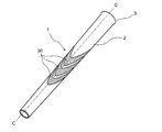
- FIG. 8 is a perspective view showing an example of a golf club grip.
- the grip 1 has a cylindrical portion 2 into which a shaft is inserted, and a cap portion 3 integrally formed so as to cover an opening at a rear end of the cylindrical portion.
- a narrow groove region 30 is formed in a range of 10% to 60% of the cylindrical portion.
- the narrow groove region 30 is formed so as to be continuous in a V-shape in the circumferential direction.
- FIG. 9 is a schematic cross-sectional view of the golf club grip of FIG. 8 taken along the line CC.
- the cylindrical portion 2 includes an inner layer 2a and an outer layer 2b.
- the outer layer 2b has a uniform thickness from the front end to the rear end.
- the thickness of the inner layer 2a is formed so as to gradually increase from the front end to the rear end.
- the cap portion 3 is formed from the same rubber composition as the outer layer 2b.
- FIG. 12 is a perspective view showing an example of the golf club of the present invention.
- the golf club 4 includes a shaft 5, a head 6 attached to one end of the shaft 5, and a grip 1 attached to the other end of the shaft 4. The rear end of the shaft 5 is fitted into the cylindrical portion 2 of the grip 1.
- the dynamic friction coefficient was measured using a static / dynamic friction measuring device (TL201Ts, manufactured by Trinity Lab Co., Ltd.). Specifically, a rubber piece (width 2 cm, length 6 cm) was cut out from the golf club grip and used as a test piece. The rubber piece was cut out from a portion where a narrow groove region of the grip (grip Nos. 1 to 18 was a narrow groove region and grips Nos. 19 to 23 were a groove region) was formed. In addition, grip No. For No. 24, since no narrow groove region was formed, a rubber piece was cut out near the center in the axial direction of the grip.
- T201Ts static / dynamic friction measuring device
- the test piece was fixed to the moving table of the apparatus, and the dynamic friction in the narrow groove area or the groove area of the test piece was measured using a tactile contact provided with a geometric fingerprint pattern.
- the moving distance was 1 cm
- the moving speed was 1 mm / sec
- the load was 25 g.
- the kinetic friction coefficient an average value of 0.35 cm to 0.65 cm was obtained, with the position at which the shifting movement was started being 0 cm.
- the dynamic friction coefficient is determined by the grip No.
- the dynamic friction coefficient of No. 24 was set to 100, and the value was indexed.
- a grip was attached to a shaft to produce a golf club. This golf club was subjected to a wet feeling test for 10 golfers. The feeling of wet feeling was evaluated before and after the grip was wetted, and the feeling of the wet feeling of the grip caused by the wet grip was evaluated. Then, the case where eight or more persons judged that there was no difference was evaluated as “ ⁇ ”, and the case where the number was seven or less was evaluated as “ ⁇ ”.
- a grip was attached to a shaft to produce a golf club.
- the golf club was subjected to 1000 actual hitting durability evaluations.
- the narrow groove region of the grip after hitting and the island portion of the groove region were observed, and the case where chipping was observed in the island portion was evaluated as “x”, and the case where chipping was not observed was evaluated as “ ⁇ ”.
- Head Speed A golf club (driver) (manufactured by Sumitomo Rubber Industries, Ltd., XXIO8 (flex: S)) was replaced with a grip to be tested to produce a test golf club.
- the head speed was measured using the measurement system described in JP-A-2012-170532, and the average value of 10 heads was calculated. , The head speed is shown as a difference from the head speed of Grip No. 24.
- NR natural rubber
- TSR20 EPDM ethylene-propylene-diene rubber
- Esplen registered trademark
- IIR JSR Corporation
- JSR BUTYL065 DIABLACK registered trademark
- N220 manufactured by Mitsubishi Chemical Corporation
- carbon black registered trademark
- Ultra Jill VN3 GR Evonik Co.
- granulated silica amorphous
- Sulfur 5% oil-containing fine powder sulfur (200 mesh) manufactured by Tsurumi Chemical Industry Co., Ltd.
- Noxeller NS Nt-butyl-2-benzothiazolylsulfenamide manufactured by Ouchi Shinko Chemical Co., Ltd.
- Noxeller CZ N-cyclohexyl-2-benzothiazolylsulfenamide Succinol D manufactured by Ouchi Shinko Chemical Co., Ltd. : 1,3-diphenylguanidine, manufactured by Sumitomo Chemical Co., Ltd.
- Zinc oxide PT.
- White seal Nocrack (registered trademark) NS-6, manufactured by INDO LYSAGHT, manufactured by Ouchi Shinko Chemical Co., Ltd., 2,2'-methylenebis (4-methyl-6-t-butylphenol) Santogaard PVI: Sanshin Chemical Co., Ltd., N-cyclohexylthiophthalimide Benzoic acid: Aldrich stearic acid: NOF Corporation, Beads stearic acid Tsubaki PW380: Idemitsu Kosan, Diana Process Oil PW380 Microballoon: "EXPANCEL (registered trademark) 909-80DU” (manufactured by Akzo Nobel Co., Ltd.) (resin capsule having a low boiling point hydrocarbon encapsulated in a thermoplastic resin shell, volume average particle diameter 18 ⁇ m to 24 ⁇ m, expansion start temperature 120) °C -130 °C)
- the thickness of the cylindrical portion of the obtained grip having no narrow groove was 1.5 mm at the thinnest portion (end on the head side) and 6.7 mm at the thickest portion (end on the grip end side).
- Grip No. 14 Using the rubber composition for an outer layer, a fan-shaped unvulcanized rubber sheet and a cap member were produced.
- the rubber sheet was formed so as to gradually increase in thickness from one end to the other end.
- a rubber sheet was wound around the mandrel, and the mandrel and the cap member around which the rubber sheet was wound were put into a mold. Then, a heat treatment was performed at a mold temperature of 160 ° C. and a heating time of 15 minutes to obtain a grip having no narrow groove on the outer layer surface.
- the thickness of the cylindrical portion of the obtained grip having no narrow groove was 1.5 mm at the thinnest portion (end on the head side) and 6.7 mm at the thickest portion (end on the grip end side).
- Grip No. 1 to 23 Using the laser processing machine (Amada Miyachi Co., Ltd., fiber laser processing machine, "ML-7320DL"), the grooves shown in Tables 3 to 5 were formed on the grip having no fine groove obtained above, and the narrow groove area was formed. Alternatively, a groove region was provided.
- the forming range of the narrow groove area or the groove area of each grip is as follows. Note that the tip side end of the cylindrical portion of the grip is 0%, and the butt side end is 100%. Grip No. Grip Nos. 1 to 9, 14 to 17 and 19 to 22 are in the range of 20% to 100%; Grip No. 10 is in the range of 26% to 36%; Grip Nos.
- 11 and 23 range from 18% to 58%; 12 is in the range of 18% to 78%; 13 was formed in the range of 0% to 100%. In the above range, the narrow groove region or the groove region was formed all around the cylindrical portion. Tables 3 to 5 show the evaluation results of each grip.
- Grip No. Nos. 1 to 19 are the cases where at least a part of the surface of the cylindrical portion has a narrow groove region where the occupation ratio of the narrow groove per 25 mm 2 is 35% or more.
- grip no. In Nos. 1 to 14 the interval between the narrow grooves in the narrow groove region is 0.3 to 1.5 mm, and the total area of the narrow groove region is 1400 mm 2 or more.
- These grip Nos. Nos. 1 to 14 are excellent in anti-slip performance, feeling when wet and durability, and have improved head speed.
- Grip No. 15 the interval between the narrow grooves is 0.15 mm, and the durability is poor.
- Grip No. 16 and 17 the interval between the narrow grooves was 1.8 mm or 2.0 mm, the feeling was poor, and the head speed was not improved.
- Grip No. In No. 18, the total area of the narrow groove region is 1383 mm 2 , and the feeling when wet is inferior.
- grip pattern No. 18 It is considered that the pattern is the same as the pattern of the narrow groove areas 10 and 11 but the introduction area is small, so that the friction coefficient is different.
- Grip No. Nos. 19 to 23 have groove regions in which the occupation ratio of grooves per 25 mm 2 is 35% or more on the surface of the cylindrical portion.
- grip no. In No. 19 the width of the groove is less than 0.1 mm, and the feeling when wet is inferior.
- Grip No. In Nos. 20 and 21 the groove width was more than 0.7 mm, the anti-slip performance and feeling were poor, and the head speed was not improved.
- the depth of the groove is less than 0.1 mm, and the feeling when wet is inferior.
- Grip No. No. 23 has a groove depth of more than 1.0 mm, and is inferior in feeling and durability.
Landscapes
- Health & Medical Sciences (AREA)
- General Health & Medical Sciences (AREA)
- Physical Education & Sports Medicine (AREA)
- Golf Clubs (AREA)
Abstract
【課題】防滑性能、ウェット時のフィーリングに優れたゴルフクラブ用グリップを提供する。また、さらに耐久性に優れ、ヘッドスピードが向上するゴルフクラブ用グリップを提供する。 【解決手段】ゴルフクラブ用グリップは、シャフトが挿嵌される円筒部を有するグリップであって、前記円筒部の表面の少なくとも一部に、25mm2当たりの細溝の占有率が35%以上である細溝領域を有し、前記細溝の幅(w)が0.1mm~0.7mm、細溝の深さ(h)が0.1mm~1.0mmであることを特徴とする。また、前記細溝の間隔(d)が、1.5mm以下であることが好ましい。
Description
本発明は、ゴルフクラブ用グリップに関する。
ゴルフクラブは、シャフトと、このシャフトの前端近傍に装着されたヘッドと、シャフトの後端近傍が挿嵌されるグリップとから構成されている。グリップは、ゴルフクラブをスイングするゴルファーが手で把持する部分であり、ゴルファーの運動がゴルフクラブに伝達される際に極めて重要な役割を果たす部分である。グリップの重要な要求性能として、スイング中にゴルファーの手とグリップとの滑りが抑制されることが挙げられる。
一般にグリップは、ゴム、合成樹脂等の柔軟な材料から成形されており、さらに防滑性能を高めるために、その表面に溝や凹みのパターンが形成されている(例えば、特許文献1(段落0035、図4)参照)。
また、特許文献2には、グリップ表面に高さが異なるステムの個別のゾーンを有するステム配列を形成したグリップが提案されている(特許文献2(段落0040~0043)参照)。この特許文献2のグリップでは、第1ゾーンには、約0.020~約0.030インチ(0.508~0.762mm)の高さを有するステムが形成されている。
引用文献2には、グリップの防滑性能を高めるために、グリップ表面に微細な突起を設けることが提案されている。しかしながら、突起の形状を微細にした場合、突起の強度を維持するために突起間の溝の深さを浅くする必要がある。そのため、ゴルファーの汗、雨などの水分が、微細突起に留まりやすくなり、グリップ表面のドライ性が低下する傾向がある。
本発明は上記事情に鑑みてなされたものであり、防滑性能、ウェット時のフィーリングに優れたゴルフクラブ用グリップを提供することを目的とする。
上記課題を解決することができた本発明のゴルフクラブ用グリップは、シャフトが挿嵌される円筒部を有し、前記円筒部の表面の少なくとも一部に、25mm2当たりの細溝の占有率が35%以上である細溝領域を有し、前記細溝の幅(w)が0.1mm~0.7mm、細溝の深さ(h)が0.1mm~1.0mmであることを特徴とする。
前記グリップは、特定の幅および深さを有する細溝が一定量形成された細溝領域を有している。この細溝領域は、ゴルファーの汗や雨などの水分を細溝内部へと取込むことができ、グリップ表面をドライな状態に保つことができる。また、前記グリップは、細溝によって区切られることで出現する島部が、使用者の皮膚にひっかかることによって防滑性能が向上する。
本発明には、シャフトと、前記シャフトの一端に取り付けられたヘッドと、前記シャフトの他端に取り付けられたグリップとを備え、前記グリップが、前記ゴルフクラブ用グリップであるゴルフクラブも含まれる。
本発明によれば、防滑性能、ウェット時のフィーリングに優れるゴルフクラブ用グリップが得られる。
本発明のゴルフクラブ用グリップは、シャフトが挿嵌される円筒部を有し、前記円筒部の表面の少なくとも一部に、25mm2当たりの細溝の占有率が35%以上である細溝領域を有する。前記グリップは、特定の幅および深さを有する細溝が一定量形成された細溝領域を有している。この細溝領域は、ゴルファーの汗や雨などの水分を細溝内部へと取込むことができ、グリップ表面をドライな状態に保つことができる。また、前記グリップは、細溝によって区切られることで出現する島部が、使用者の皮膚にひっかかることによって防滑性能が向上する。
(細溝領域)
前記細溝領域とは、特定の細溝が一定の占有率となるように形成された領域である。前記細溝領域における細溝の占有率は、25mm2(5mm×5mm四方)当たり35%以上、好ましくは38%以上、より好ましくは40%以上であり、65%以下が好ましく、より好ましくは60%以下、さらに好ましくは55%以下である。細溝の占有率が35%以上であれば細溝から水が溢れにくく、ウェット時のフィーリングが良好となる。また、細溝の占有率が65%以下であれば接触面積の低下による滑りを感じることがなく、防滑性能が良好となる。なお、占有率は、単位面積における細溝の面積の割合である。細溝の面積は、グリップの表面を顕微鏡で観察して測定してもよいし、グリップ表面における細溝の幅(w)、細溝の長さ、および、細溝の本数から算出してもよい。なお、細溝領域には、後述する細溝以外の溝が形成されていてもよいが、上記面積を算出する際には、細溝の面積のみを計測することとする。
前記細溝領域とは、特定の細溝が一定の占有率となるように形成された領域である。前記細溝領域における細溝の占有率は、25mm2(5mm×5mm四方)当たり35%以上、好ましくは38%以上、より好ましくは40%以上であり、65%以下が好ましく、より好ましくは60%以下、さらに好ましくは55%以下である。細溝の占有率が35%以上であれば細溝から水が溢れにくく、ウェット時のフィーリングが良好となる。また、細溝の占有率が65%以下であれば接触面積の低下による滑りを感じることがなく、防滑性能が良好となる。なお、占有率は、単位面積における細溝の面積の割合である。細溝の面積は、グリップの表面を顕微鏡で観察して測定してもよいし、グリップ表面における細溝の幅(w)、細溝の長さ、および、細溝の本数から算出してもよい。なお、細溝領域には、後述する細溝以外の溝が形成されていてもよいが、上記面積を算出する際には、細溝の面積のみを計測することとする。
前記細溝領域に形成される細溝は、幅(w)が0.1mm~0.7mmである。細溝の幅が、この範囲内であれは、ゴルファーの汗などの水分を細溝内部へと取込みやすくなる。前記細溝の幅は、0.2mm以上が好ましく、より好ましくは0.3mm以上であり、0.6mm以下が好ましく、より好ましくは0.5mm以下である。細溝の幅は、グリップの表面における幅を測定する。測定は、マイクロメーター等を用いればよい。
前記細溝の深さ(h)は、0.1mm~1.0mmである。細溝の深さが、この範囲内であれは、ゴルファーの汗などの水分を細溝内部へと取込みやすくなる。前記細溝の深さは、0.2mm以上が好ましく、より好ましくは0.3mm以上であり、0.8mm以下が好ましく、より好ましくは0.7mm以下である。なお、溝の幅は、深さ方向に一定であってもよいし、グリップ表面における幅と最深部での幅とが異なっていてもよい。溝の幅は、深くなるほど幅が狭くなるように形成してもよいし、段階的に狭くなるように形成してもよい。前記細溝のグリップ表面における幅(ws)と、細溝の最深部における幅(wd)との比(wd/ws)は、1.0以下が好ましく、より好ましくは0.8以下、さらに好ましくは0.6以下である。前記溝の断面形状としては、V字状、略V字状、U字状などが挙げられる。
前記細溝領域に形成される細溝は、一種類の細溝を複数形成してもよいし、複数種類の細溝を組合せて形成してもよい。前記細溝の形状は、直線状、曲線状など特に限定されないが、直線状であることが好ましい。また、前記細溝の幅、深さは、一定であることが好ましい。
前記細溝領域において、細溝の平均長さは、10mm以上が好ましく、より好ましくは20mm以上、さらに好ましくは30mm以上である。前記細溝の平均長さが10mm以上であれば、細溝に取込んだ水分を細溝内で拡散することができ、ゴルファーの汗などの水分を細溝内部へとより取込みやすくなる。
前記細溝領域において、細溝の間隔(d)は、1.5mm以下が好ましく、より好ましくは1.2mm以下、さらに好ましくは1.0mm以下である。細溝の間隔が1.5mm以下であれば、細溝間に形成される島部が皮膚に引っかかりやすくなり、フィーリングがより良好となる。そのため、使用者のグリップを握る力が無意識的に弱くなり、スイングに対する体の抵抗が小さくなることで、ヘッドスピードが向上する。また、複数の細溝を互いに平行となるように形成する場合、細溝の間隔は、0.3mm以上が好ましく、より好ましくは0.4mm以上、さらに好ましくは0.5mm以上である。細溝の間隔が0.3mm以上であれば、細溝間に形成される島部の機械的強度が高くなり、耐久性がより向上する。なお、細溝の間隔は一定でもよいし、異なっていてもよい。
前記細溝の間隔(d)と、前記細溝の幅(w)との比(d/w)は、1以上が好ましく、より好ましくは1.5以上、さらに好ましくは2以上であり、5以下が好ましく、より好ましくは4.5以下、さらに好ましくは4以下である。比(d/w)が上記範囲内であれば、打撃時のフィーリングがより良好となる。
前記細溝は、他の細溝と交差するように形成されていることが好ましい。細溝が交差していることで、細溝に取込まれた汗や雨が他の細溝へと拡散することができ、グリップ表面をよりドライな状態に保つことができる。また、前記グリップ表面は、細溝によって区切られることで、島部が形成されていることが好ましい。細溝によって区切られることで出現する島部が、使用者の皮膚にひっかかることによって防滑性能が向上する。前記細溝としては、互いに平行に形成される第1の細溝群と、この第1の細溝群と交差するように形成され、かつ、互いに平行に形成される第2の細溝群とを有することが好ましい。これらの第1の細溝群と第2の細溝群とを形成することで、細溝の占有率を制御しやすくなる。
前記第1の細溝群と第2の細溝群とを形成する場合、これらのなす角は、45°以上が好ましく、より好ましくは60°以上、さらに好ましくは80°以上であり、135°以下が好ましく、より好ましくは120°以下、さらに好ましくは100°以下である。これらの細溝群のなす角が前記範囲内であれば、細溝群の間に形成される島部の機械的強度が高くなり、耐久性がより向上する。
前記細溝領域は、前記円筒部のチップ側端部を0%、バット側端部を100%としたとき、前記円筒部の10%~100%の範囲の少なくとも一部に設けられていることが好ましく、より好ましくは15%~80%の範囲、さらに好ましくは20%~70%の範囲である。
前記細溝領域は、円筒部の10%~60%までの範囲に形成することが特に好ましい。この場合、円筒部の10%~60%までの範囲の表面積において、細溝領域の面積率は30面積%以上が好ましく、より好ましくは40面積%以上、さらに好ましくは50面積%以上であり、95面積%以下が好ましく、より好ましくは90面積%以下、さらに好ましくは85面積%以下である。前記チップ側端部からの軸方向の距離が全長の10%~60%までの範囲は、使用者が素手でグリップを握る部分である。この部分に細溝領域を有することで、グリップの感触がより良好となる。
前記細溝領域は、前記円筒部の周方向に連続するように形成されていることが好ましい。このように形成することで、細溝に取込まれたゴルファーの汗などを拡散させやすくなる。なお、周方向に連続するとは、周方向に直線的に連続している形態だけでなく、周方向にV字状やU字状に連続している形態も含む。前記細溝領域の周方向の長さは、円筒部の周長の10%以上が好ましく、より好ましくは20%以上、さらに好ましくは30%以上であり、100%以下である。
前記細溝領域は、1箇所のみ形成してもよいし、複数箇所に形成してもよい。前記細溝領域の総面積は、1400mm2以上が好ましく、より好ましくは2800mm2以上、さらに好ましくは4200mm2以上である。総面積が1400mm2以上であれば、フィーリングがより良好となり、ヘッドスピードが向上する。また、個々の細溝領域の面積は、180mm2以上が好ましく、より好ましくは360mm2以上、さらに好ましくは540mm2以上である。
前記細溝領域は、レーザ加工、金型からの転写により形成することができ、レーザ加工により形成することが好ましい。レーザ加工により形成することで、細溝を容易に形成できる。
図1~7を参照し、細溝領域に形成される細溝について説明する。図1は、細溝領域の一例を示す平面図である。図2は、図1の細溝領域のA-A断面図である。図3は、図1の細溝領域のB-B断面図である。図4は、細溝領域の他の一例を示す平面図である。図5は、図4の細溝領域のA-A断面図である。図6は、図4の細溝領域のB-B断面図である。図7は、細溝領域の他の一例を示す平面図である。
図1、4、7の細溝領域では、第1の細溝群10と第2の細溝群20が形成されている。第1の細溝群10の幅W1および間隔d1は一定に形成されている。第2の細溝群20の幅W2および間隔d2は一定に形成されている。また、図1、4、7の細溝領域では、第1の細溝群10の幅w1と第2の細溝群20の幅w2が同一であり、第1の細溝群10の間隔d1と第2の細溝群20の間隔d2が同一である。
図1、4の細溝領域において、第1の細溝群10の方向をX、第2の細溝群20の方向をYとすると、第1の細溝群10と第2の細溝群20とがなす角θは90°である。よって、細溝によって形成された島部の平面視形状は正方形となっている。
図1の細溝領域では、第1の細溝群10の幅w1および第2の細溝群20の幅w2は、深さ方向に一定に形成されている。よって、細溝によって形成された島部の断面形状は四角柱となっている。図4の細溝領域では、第1の細溝群10の幅w1および第2の細溝群20の幅w2は、深くなるにつれて狭くなるように形成されている。よって、細溝によって形成された島部の断面形状は四角錐台となっている。
図7は、細溝領域において、第1の細溝群10の方向をX、第2の細溝群20の方向をYとすると、第1の細溝群10と第2の細溝群20とがなす角θは45°である。よって、細溝によって形成された島部の平面視形状は菱形となっている。
[構造]
前記ゴルフクラブ用グリップの円筒部は、単層構造でもよいし、多層構造でもよい。円筒部が単層構造の場合は、細溝領域と、細溝領域以外の他の領域(以下、単に「他の領域」と称する場合がある。)とを異なる組成物から形成してもよいし、同一の組成物から形成してもよい。なお、単層構造の円筒部は、細溝領域および他の領域が、いずれも中実層であることが好ましい。
前記ゴルフクラブ用グリップの円筒部は、単層構造でもよいし、多層構造でもよい。円筒部が単層構造の場合は、細溝領域と、細溝領域以外の他の領域(以下、単に「他の領域」と称する場合がある。)とを異なる組成物から形成してもよいし、同一の組成物から形成してもよい。なお、単層構造の円筒部は、細溝領域および他の領域が、いずれも中実層であることが好ましい。
円筒部が多層構造の場合、円筒部は最表層と少なくとも一層の内層とを有する。前記最表層が細溝領域を有する。ここで、最表層とは、グリップの最も外側の層であり、グリップ使用時に使用者が触れる部分である。前記最表層は、細溝領域と他の領域とを異なる組成物から形成してもよいし、同一の組成物から形成してもよい。なお、最表層は、細溝領域および他の領域が、いずれも中実層であることが好ましい。前記内層は、少なくとも一層が多孔質層であることが好ましい。円筒部を多層構造とする場合、最表層と1層の内層とを有する2層構造;最表層と2層の内層とを有する3層構造;が好ましい。
前記円筒部の厚さは、0.5mm以上が好ましく、より好ましくは1.0mm以上、さらに好ましくは1.5mm以上であり、17.0mm以下が好ましく、より好ましくは10.0mm以下、さらに好ましくは8.0mm以下である。前記円筒部の厚さは、軸方向に一定となるように形成してもよいし、先端部から後端部に向かって徐々に厚くなるように形成してもよい。
前記円筒部の厚さが0.5mm~17.0mmの場合、前記最表層の厚さは、0.5mm以上が好ましく、より好ましくは0.6mm以上、さらに好ましくは0.7mm以上であり、2.5mm以下が好ましく、より好ましくは2.3mm以下、さらに好ましくは2.1mm以下である。前記外層の厚さが0.5mm以上であれば外層素材による補強効果がより大きくなり、2.5mm以下であれば相対的に内層を厚くすることができ、グリップの軽量化の効果が大きくなる。
前記円筒部の厚さに対する最表層の厚さの百分率((最表層厚さ/円筒部厚さ)×100)は、0.5%以上が好ましく、より好ましくは1.0%以上、さらに好ましくは1.5%以上であり、99.0%以下が好ましく、より好ましくは98.0%以下、さらに好ましくは97.0%以下である。前記百分率が0.5%以上であれば外層素材による補強効果がより大きくなり、99.0%以下であれば相対的に内層を厚くすることができ、グリップの軽量化の効果が大きくなる。
[材質]
前記円筒部の材質は特に限定されず、従来ゴルフクラブ用グリップに使用されているゴム組成物、樹脂組成物から形成できる。
前記円筒部の材質は特に限定されず、従来ゴルフクラブ用グリップに使用されているゴム組成物、樹脂組成物から形成できる。
前記円筒部は、前記細溝領域が、ゴム組成物から形成されていることが好ましい。細溝領域をゴム組成物から形成することで、島部のチッピングの発生を抑制できる。前記細溝領域を構成するゴム組成物(以下、「第1ゴム組成物」と称する場合がある。)としては、基材ゴムと架橋剤とを含有することが好ましい。
前記基材ゴムとしては、天然ゴム(NR)、エチレン-プロピレン-ジエンゴム(EPDM)、ブチルゴム(IIR)、アクリロニトリル-ブタジエンゴム(NBR)、水素添加アクリロニトリル-ブタジエンゴム(HNBR)、カルボキシ変性アクリロニトリル-ブタジエンゴム(XNBR)、カルボキシ変性水素添加アクリロニトリル-ブタジエンゴム(HXNBR)、ブタジエンゴム(BR)、スチレン-ブタジエンゴム(SBR)、ポリウレタンゴム(PU)、イソプレンゴム(IR)、クロロプレンゴム(CR)、エチレン-プロピレンゴム(EPM)などが挙げられる。これらの基材ゴムは、単独で使用してもよいし、2種以上を併用してもよい。
前記基材ゴムは、非極性ゴムを含有することが好ましい。基材ゴムが非極性ゴムを含有率すれば、グリップに使用者の皮脂が付着した場合でも、グリップが油分を吸収することができる。そのため、使用者の皮脂による防滑性能の低下を抑制できる。前記基材ゴム中の非極性ゴムの含有率は、50質量%以上が好ましく、より好ましくは60質量%以上、さらに好ましくは70質量%以上である。前記非極性ゴムは、SP(溶解度パラメーター)値が7.7以上、8.7未満である。
前記SP値は、Fedorsの式(下記数式(1))(Polymer Engineering and Science、第14巻、第2号、1974年、第147頁)により求められる値(Pa1/2(25℃))である。
SP値=(ΔE/V)1/2=(ΣΔei/ΣΔvi)1/2 (1)
[式(1)中、ΔEは蒸発エネルギー、Vはモル体積、Δeiは原子または原子団の蒸発エネルギー、Δviは原子または原子団のモル体積を表す。]
SP値=(ΔE/V)1/2=(ΣΔei/ΣΔvi)1/2 (1)
[式(1)中、ΔEは蒸発エネルギー、Vはモル体積、Δeiは原子または原子団の蒸発エネルギー、Δviは原子または原子団のモル体積を表す。]
前記非極性ゴムとしては、例えば、イソプレンゴム(IR)、ブタジエンゴム(BR)、スチレン-ブタジエンゴム(SBR)、クロロプレンゴム(CR)、天然ゴム(NR)、などのジエン系ゴム;エチレン-プロピレンゴム(EPM)、エチレン-プロピレン-ジエンゴム(EPDM)、ブチルゴム(IIR)などの非ジエンゴムが挙げられる。非極性ゴムが単独で使用してもよいし、2種以上を併用してもよい。これらの中でも、ジエン系ゴムが好ましく、非極性ゴム中のジエン系ゴムの含有率は50質量%以上が好ましく、より好ましくは60質量%以上である。非極性ゴムとしてジエン系ゴムのみを使用することも好ましい。前記非極性ゴムとしては、NR、EPDM、IIR、SBRがより好ましい。
前記第1ゴム組成物は、基材ゴムとして、天然ゴムを含有することが好ましい。天然ゴムを含有することで、寒冷条件下においても島部の柔軟性が維持され、高い防滑性能を維持できる。基材ゴムとして天然ゴムを使用する場合、基材ゴム中の天然ゴムの含有率は50質量%以上が好ましく、より好ましくは55質量%以上、さらに好ましくは60質量%以上である。
前記架橋剤としては、硫黄系架橋剤、有機過酸化物を使用できる。前記硫黄系架橋剤としては単体硫黄、硫黄ドナー型化合物が挙げられる。前記単体硫黄としては、粉末硫黄、沈降硫黄、コロイド状硫黄、不溶性硫黄が挙げられる。前記硫黄ドナー型化合物としては、4,4’-ジチオビスモルホリンなどが挙げられる。前記有機過酸化物としては、ジクミルパーオキサイド、α,α’-ビス(t-ブチルパーオキシ-m-ジイソプロピル)ベンゼン、2,5-ジメチル-2,5-ジ(t-ブチルパーオキシ)ヘキサン、1,1-ビス(t-ブチルパーオキシ)3,3,5-トリメチルシクロヘキサンなどが挙げられる。前記架橋剤は単独で使用してもよいし、2種以上を併用してもよい。前記架橋剤としては、硫黄系架橋剤が好ましく、単体硫黄がより好ましい。前記架橋剤の使用量は、基材ゴム100質量部に対して、0.2質量部以上が好ましく、より好ましくは0.4質量部以上、さらに好ましくは0.6質量部以上であり、4.0質量部以下が好ましく、より好ましくは3.5質量部以下、さらに好ましくは3.0質量部以下である。
前記第1ゴム組成物は、さらに加硫促進剤、加硫活性剤を含有することが好ましい。
前記加硫促進剤としては、テトラメチルチウラムジスルフィド(TMTD)、テトラベンジルチウラムジスルフィド(TBzTD)、テトラメチルチウラムモノスルフィド(TMTM)、ジペンタメチレンチウラムテトラスルフィドなどのチウラム系;ジフェニルグアニジン(DPG)などのグアニジン系;ジメチルジチオカルバミン酸亜鉛(ZnPDC)、ジブチルジチオカルバミン酸亜鉛などのジチオカルバミン酸塩系;トリメチルチオ尿素、N,N'-ジエチルチオ尿素などのチオウレア系;メルカプトベンゾチアゾール(MBT)、ベンゾチアゾールジスルフィドなどのチアゾール系;N-シクロヘキシル-2-ベンゾチアゾリルスルフェンアミド(CBS)、N-t-ブチル-2-ベンゾチアゾリルスルフェンアミド(BBS)などのスルフェンアミド系;などが挙げられる。これらの加硫促進剤は、単独で使用してもよいし、2種以上を併用してもよい。前記加硫促進剤の合計使用量は、基材ゴム100質量部に対して、0.4質量部以上が好ましく、より好ましくは0.8質量部以上、さらに好ましくは1.2質量部以上であり、8.0質量部以下が好ましく、より好ましくは7.0質量部以下、さらに好ましくは6.0質量部以下である。
前記加硫活性剤としては、金属酸化物(酸化チタンを除く。)、金属過酸化物、脂肪酸などが挙げられる。前記金属酸化物としては、酸化亜鉛、酸化マグネシウム、酸化鉛などが挙げられる。前記金属過酸化物としては、過酸化亜鉛、過酸化クロム、過酸化マグネシウム、過酸化カルシウムなどが挙げられる。前記脂肪酸としては、ステアリン酸、オレイン酸、パルミチン酸などが挙げられる。これらの加硫活性剤は、単独で使用してもよいし、2種以上を併用してもよい。前記加硫活性剤の合計使用量は、基材ゴム100質量部に対して、0.5質量部以上が好ましく、より好ましくは0.6質量部以上、さらに好ましくは0.7質量部以上であり、10.0質量部以下が好ましく、より好ましくは9.5質量部以下、さらに好ましくは9.0質量部以下である。
前記第1ゴム組成物は、さらに必要に応じて、老化防止剤、軟化剤、着色剤、スコーチ防止剤、樹脂などを配合してもよい。
前記老化防止剤としては、イミダゾール類、アミン類、フェノール類、チオウレア類などが挙げられる。前記イミダゾール類としては、ジブチルジチオカルバミン酸ニッケル(NDIBC)、2-メルカプトベンズイミダゾール、2-メルカプトベンズイミダゾールの亜鉛塩などが挙げられる。アミン類としては、フェニル-α-ナフチルアミンなどが挙げられる。フェノール類としては、2,2’-メチレンビス(4-メチル-6-t-ブチルフェノール)(MBMBP)、2,6-ジ-tert-ブチル-4-メチルフェノールなどが挙げられる。チオウレア類としては、トリブチルチオ尿素、1,3-ビス(ジメチルアミノプロピル)-2-チオ尿素などが挙げられる。これらの老化防止剤は単独で使用してもよいし、2種以上を併用してもよい。前記老化防止剤の使用量は、基材ゴム100質量部に対して、0.2質量部以上が好ましく、より好ましくは0.3質量部以上、さらに好ましくは0.4質量部以上であり、5.0質量部以下が好ましく、より好ましくは4.8質量部以下、さらに好ましくは4.6質量部以下である。
前記軟化剤としては、鉱物油、可塑剤が挙げられる。前記鉱物油としては、パラフィンオイル、ナフテンオイル、アロマチックオイルなどが挙げられる。前記可塑剤としては、ジオクチルフタレート、ジブチルフタレート、ジオクチルセパケート、ジオクチルアジペートなどが挙げられる。
前記スコーチ防止剤としては、有機酸、ニトロソ化合物などが挙げられる。前記有機酸としては、無水フタル酸、無水ピロメリット酸、無水トリメリット酸、安息香酸、サリチル酸、リンゴ酸などが挙げられる。前記ニトロソ化合物としては、N-ニトロソ・ジフェニルアミン、N-(シクロヘキシルチオ)フタルイミド、スルホンアミド誘導体、ジフェニルウレア、ビス(トリデシル)ペンタエリスルトールジホスファイト、2-メルカプトベンズイミダゾールなどが挙げられる。
前記樹脂としては、水素添加ロジンエステル、不均化ロジンエステル、エチレン-酢酸ビニル共重合体、クマロン樹脂、フェノール樹脂、キシレン樹脂、スチレン樹脂などが挙げられる。
前記第1ゴム組成物は、従来公知の方法で調製できる。例えば、バンバリーミキサー、ニーダー、オープンロールなどの混練機を用いて、各原料を混練りすることで調製できる。
前記第1ゴム組成物の材料硬度(ショアA硬度)は、40以上が好ましく、より好ましくは42以上、さらに好ましくは45以上であり、60以下が好ましく、より好ましくは58以下、さらに好ましくは55以下である。第1ゴム組成物の材料硬度(ショアA硬度)が40以上であれば細溝領域の機械的強度がより向上し、60以下であれば最表層が硬くなりすぎず、掴んだ時のグリップ感がより良好となる。
単層構造の円筒部または多層構造の円筒部の最表層において、細溝領域以外の他の領域の材質は特に限定されないが、前記第1ゴム組成物から形成されていることが好ましい。なお、前記他の領域を構成するゴム組成物は、前記細溝領域を構成するゴム組成物と同一の組成でもよいし、異なる組成でもよい。これらが同一の組成であれば、円筒部または最表層の作製が容易となる。
前記円筒部が多層構造の場合、内層の材質は特に限定されない。前記内層を形成する組成物(以下、「第2組成物」と称する場合がある。)としては、第2ゴム組成物、樹脂組成物が挙げられる。
前記第2ゴム組成物は、基材ゴムと架橋剤とを含有することが好ましい。前記基材ゴムとしては、天然ゴム(NR)、エチレン-プロピレン-ジエンゴム(EPDM)、ブチルゴム(IIR)、アクリロニトリル-ブタジエンゴム(NBR)、水素添加アクリロニトリル-ブタジエンゴム(HNBR)、カルボキシ変性アクリロニトリル-ブタジエンゴム(XNBR)、カルボキシ変性水素添加アクリロニトリル-ブタジエンゴム(HXNBR)、ブタジエンゴム(BR)、スチレン-ブタジエンゴム(SBR)、ポリウレタンゴム(PU)、イソプレンゴム(IR)、クロロプレンゴム(CR)、エチレン-プロピレンゴム(EPM)などが挙げられる。これらの中でも、前記基材ゴムとしては、NR、EPDM、IIR、NBR、HNBR、XNBR、HXNBR、BR、SBR、PUが好ましい。
前記第2ゴム組成物の架橋剤としては、前記第1ゴム組成物に使用されるものと同じものが挙げられ、単体硫黄が好ましい。前記第2ゴム組成物は、さらに加硫促進剤、加硫活性剤を含有することが好ましい。これらの加硫促進剤、加硫活性剤としては前記第1ゴム組成物に使用されるものと同じものが挙げられる。前記加硫促進剤としては、N-t-ブチル-2-ベンゾチアゾリルスルフェンアミド、テトラベンジルチウラムジスルフィドが好ましい。前記加硫活性剤としては、酸化亜鉛、ステアリン酸が好ましい。
前記第2ゴム組成物は、さらに必要に応じて補強材、老化防止剤、軟化剤、着色剤、スコーチ防止剤などを配合してもよい。これらの補強材、老化防止剤、着色剤としては前記第1ゴム組成物に使用されるものと同じものが挙げられる。前記補強材としては、カーボンブラック、シリカが好ましい。前記老化防止剤としては、2,2’-メチレンビス(4-メチル-6-t-ブチルフェノール)が好ましい。
前記第2ゴム組成物は、従来公知の方法で調製できる。例えば、バンバリーミキサー、ニーダー、オープンロールなどの混練機を用いて、各原料を混練りすることで調製できる。混練りする際の温度(材料温度)は、70℃~160℃が好ましい。なお、第2ゴム組成物がマイクロバルーンを含有する場合は、マイクロバルーンの膨張開始温度未満の温度で混練りすることが好ましい。
前記樹脂組成物は、基材樹脂を含有する。前記基材樹脂としては、ポリウレタン樹脂、ポリスチレン樹脂、ポリエチレン樹脂、ポリプロピレン樹脂、エチレン酢酸ビニル共重合体樹脂、ポリエチレンテレフタレート樹脂などが挙げられる。
前記他の部分を形成する第2組成物としては、第2ゴム組成物が好ましく、基材ゴムとして天然ゴム(NR)、エチレン-プロピレン-ジエンゴム(EPDM)、ブチルゴム(IIR)を含有することが好ましい。他の部分を形成する組成物が天然ゴム(NR)、エチレン-プロピレン-ジエンゴム(EPDM)、ブチルゴム(IIR)を含有することで、第1ゴム組成物から形成される部分と他の部分との密着性が向上する。
前記内層は、中実層でもよいし、多孔質層でもよい。前記内層を多孔質層とすれば、ゴルフクラブ用グリップを軽量化できる。多孔質層は、基材となるゴムに多数の細孔(空隙)が形成されている層である。多数の細孔が形成されていることにより、層の見掛け密度が小さくなり、軽量化を図ることができる。
多孔質層を作製する方法としては、バルーン発泡法、化学発泡法、超臨界二酸化炭素射出成型法、塩抽出法、溶剤除去法などが挙げられる。前記バルーン発泡法では、ゴム組成物にマイクロバルーンを含有させ、加熱によりマイクロバルーンを膨張させて、発泡させる。なお、ゴム組成物に膨張済みのマイクロバルーンを配合し、それを成形してもよい。前記化学発泡法では、ゴム組成物に発泡剤(アゾジカルボンアミド、アゾビスイソブチロニトリル、N,N-ジニトロソペンタメチレンテトラミン、p-トルエンスルホニルヒドラジン、p-オキシビス(ベンゼンスルホヒドラジド)など)や発泡助剤を含有させ、化学反応により気体(炭酸ガス、窒素ガスなど)を発生させて発泡させる。前記超臨界二酸化炭素射出成型では、高圧力下で超臨界状態にある二酸化炭素をゴム組成物に含侵させ、このゴム組成物を常圧下に射出し、二酸化炭素を気化させて発泡させる。前記塩抽出法では、ゴム組成物に易溶解性塩(ホウ酸、塩化カルシウムなど)を含有させ、成形後に塩を溶解抽出して細孔を形成する。前記溶剤除去法では、ゴム組成物に溶剤を含有させ、成形後に溶剤を除去し細孔を形成する。
前記内層を多孔質層とする場合、発泡剤を含有する第2ゴム組成物から成形された発泡層が好ましい。特に、バルーン発泡法により作製された発泡層とすることが好ましい。すなわち、内層としては、マイクロバルーンを含有する第2ゴム組成物から成形された発泡層が好ましい。マイクロバルーンを用いることで、内層の機械的強度を維持しつつ、軽量化を図ることができる。
前記マイクロバルーンとしては、有機マイクロバルーン、無機マイクロバルーンのいずれも使用できる。有機マイクロバルーンとしては、熱可塑性樹脂からなる中空粒子、熱可塑性樹脂の殻に低沸点炭化水素が内包された樹脂カプセルなどが挙げられる。前記樹脂カプセルの具体例としては、Akzo Nobel社製のエクスパンセル、松本油脂製薬社製のマツモトマイクロスフェアー(登録商標)などが挙げられる。無機マイクロバルーンとしては、中空ガラス粒子(シリカバルーン、アルミナバルーンなど)、中空セラミックス粒子などが挙げられる。
前記樹脂カプセル(膨張前)の体積平均粒子径は、5μm以上が好ましく、より好ましくは6μm以上、さらに好ましくは9μm以上であり、90μm以下が好ましく、より好ましくは70μm以下、さらに好ましくは60μm以下である。
バルーン発泡法により内層を作製する場合、前記第2ゴム組成物中のマイクロバルーンの含有量は、基材ゴム100質量部に対して、5質量部以上が好ましく、より好ましくは8質量部以上、さらに好ましくは12質量部以上であり、20質量部以下が好ましく、より好ましくは18質量部以下、さらに好ましくは15質量部以下である。前記マイクロバルーンの含有量が5質量部以上であればグリップの軽量化の効果がより大きくなり、20質量部以下であれば内層の機械的強度の低下を抑制できる。
また、バルーン発泡法により作製される内層の発泡倍率は、1.2以上が好ましく、より好ましくは1.5以上、さらに好ましくは1.8以上であり、5.0以下が好ましく、より好ましくは4.5以下、さらに好ましくは4.0以下である。発泡倍率が1.2以上であればグリップの軽量化の効果が大きくなり、5.0以下であれば内層の機械的強度の低下を抑制できる。
前記第2ゴム組成物の材料硬度(ショアA硬度)は、20以上が好ましく、より好ましくは25以上、さらに好ましくは30以上であり、60以下が好ましく、より好ましくは58以下、さらに好ましくは55以下である。第2ゴム組成物の材料硬度(ショアA硬度)が20以上であれば内層が軟らかくなりすぎず、掴んだ時にしっかりと固定できる感触が得られ、55以下であれば内層が硬くなりすぎず、掴んだ時のグリップ感がより良好となる。
ゴルフクラブ用グリップは、前記第1ゴム組成物を、金型内で成形することで得られる。成型方法としては、プレス成形、射出成形が挙げられる。また、内層と外層とを有するゴルフクラブ用グリップは、例えば、前記第1ゴム組成物から形成した未加硫のゴムシートと、前記第2ゴム組成物から形成した未加硫のゴムシートとの積層物を、金型内でプレス成形することで得られる。プレス成形を採用する場合、金型温度は140℃~200℃が好ましく、成形時間は5分間~40分間が好ましく、成形圧力は0.1MPa~100MPaが好ましい。
ゴルフクラブ用グリップの形状としては、例えば、シャフトが挿嵌される円筒部と、前記円筒部の後端の開口を覆うように一体形成されたキャップ部とを有する形状が挙げられる。そして、円筒部が、前記第1ゴム組成物から形成されている。さらに、前記円筒部は内層と外層との積層構造を有していることが好ましい。この場合、前記外層が第1ゴム組成物から形成される。
前記円筒部の厚みは、軸方向に一定となるように形成してもよいし、先端部から後端部に向かって徐々に厚くなるように形成してもよい。また、円筒部の厚みは、径方向に一定となるように形成してもよいし、一部に凸条部分(いわゆるバックライン)を設けてもよい。また、円筒部の表面には溝を設けてもよい。溝により、ゴルファーの手とグリップとの間の水膜形成が抑制され、ウェット状態でのグリップ性能がより向上する。さらに、グリップの防滑性能および耐摩耗性の観点から、グリップ内に補強コードを配設してもよい。
前記ゴルフクラブグリップの質量は、16g以上が好ましく、より好ましくは18g以上、さらに好ましくは20g以上であり、35g以下が好ましく、より好ましくは32g以下、さらに好ましくは30g以下である。
[ゴルフクラブ]
本発明には、前記ゴルフクラブ用グリップを用いたゴルフクラブも含まれる。前記ゴルフクラブは、シャフトと、前記シャフトの一端に取り付けられたヘッドと、前記シャフトの他端に取り付けられたグリップとを備え、前記グリップが前記ゴルフクラブ用グリップである。前記シャフトは、ステンレス鋼製や炭素繊維強化樹脂製が使用できる。前記ヘッドとしては、ウッド型、ユーティリティ型、アイアン型が挙げられる。前記ヘッドを構成する材料は、特に限定されるものではなく、例えばチタン、チタン合金、炭素繊維強化プラスチック、ステンレス鋼、マルエージング鋼、軟鉄などが挙げられる。
本発明には、前記ゴルフクラブ用グリップを用いたゴルフクラブも含まれる。前記ゴルフクラブは、シャフトと、前記シャフトの一端に取り付けられたヘッドと、前記シャフトの他端に取り付けられたグリップとを備え、前記グリップが前記ゴルフクラブ用グリップである。前記シャフトは、ステンレス鋼製や炭素繊維強化樹脂製が使用できる。前記ヘッドとしては、ウッド型、ユーティリティ型、アイアン型が挙げられる。前記ヘッドを構成する材料は、特に限定されるものではなく、例えばチタン、チタン合金、炭素繊維強化プラスチック、ステンレス鋼、マルエージング鋼、軟鉄などが挙げられる。
以下、図面を参照して、ゴルフクラブ用グリップおよびゴルフクラブについて説明する。図8は、ゴルフクラブ用グリップの一例を示す斜視図である。グリップ1は、シャフトが挿嵌される円筒部2と、前記円筒部の後端の開口を覆うように一体形成されたキャップ部3とを有する。そして、前記円筒部の10%~60%の範囲に細溝領域30が形成されている。この細溝領域30は、V字状に周方向に連続するように形成されている。
図9は、図8のゴルフクラブ用グリップのC-C断面模式図である。前記円筒部2は、内層2aと外層2bから構成されている。そして、前記外層2bは先端部から後端部にわたり厚さが均一に形成されている。前記内層2aの厚みは、先端部から後端部に向かって徐々に厚くなるように形成されている。図9に示したグリップ1では、キャップ部3は外層2bと同様のゴム組成物から形成されている。
図12は、本発明のゴルフクラブの一例を示す斜視図である。ゴルフクラブ4は、シャフト5と、前記シャフト5の一端に取り付けられたヘッド6と、前記シャフト4の他端に取り付けられたグリップ1とを備えている。グリップ1の円筒部2にシャフト5の後端が嵌入されている。
以下、本発明を実施例によって詳細に説明するが、本発明は、下記実施例によって限定されるものではなく、本発明の趣旨を逸脱しない範囲の変更、実施の態様は、いずれも本発明の範囲内に含まれる。
[評価方法]
(1)材料硬度(ショアA硬度)
ゴム組成物を用いて、160℃で8~20分間プレスして、厚み2mmのシートを作製した。なお、ゴム組成物がマイクロバルーンを含有する場合は、グリップを形成した際と同様の発泡倍率となるようにマイクロバルーンを膨張させてシートを作製した。このシートを、23℃で2週間保存し、測定基板などの影響が出ないように、3枚重ねた状態で、自動硬度計(H.バーレイス社製、デジテストII)を用いて硬度を測定した。検出器は、「Shore A」を用いた。
(1)材料硬度(ショアA硬度)
ゴム組成物を用いて、160℃で8~20分間プレスして、厚み2mmのシートを作製した。なお、ゴム組成物がマイクロバルーンを含有する場合は、グリップを形成した際と同様の発泡倍率となるようにマイクロバルーンを膨張させてシートを作製した。このシートを、23℃で2週間保存し、測定基板などの影響が出ないように、3枚重ねた状態で、自動硬度計(H.バーレイス社製、デジテストII)を用いて硬度を測定した。検出器は、「Shore A」を用いた。
(2)動摩擦係数
動摩擦係数は、静・動摩擦測定機(トリニティーラボ社製、TL201Ts)を用いて測定した。具体的には、ゴルフクラブ用グリップからゴム片(幅2cm、長さ6cm)を切り出し、これを試験片とした。ゴム片は、グリップの細溝領域(グリップNo.1~18は細溝領域、グリップNo.19~23は溝領域)が形成されている部分を切り出した。なお、グリップNo.24については、細溝領域が形成されていないため、グリップの軸方向の中央付近からゴム片を切り出した。試験片を装置の移動テーブルに固定し、幾何学指紋パターンが施された触覚接触子を使用し、試験片の細溝領域または溝領域の動摩擦を測定した。試験は、移動距離1cm、移動速度1mm/秒、荷重25gとした。動摩擦係数は、ずれ運動を開始した位置を0cmとして、0.35cm~0.65cmの平均値を求めた。なお、動摩擦係数は、グリップNo.24の動摩擦係数を100として、指数化した値で示した。
動摩擦係数は、静・動摩擦測定機(トリニティーラボ社製、TL201Ts)を用いて測定した。具体的には、ゴルフクラブ用グリップからゴム片(幅2cm、長さ6cm)を切り出し、これを試験片とした。ゴム片は、グリップの細溝領域(グリップNo.1~18は細溝領域、グリップNo.19~23は溝領域)が形成されている部分を切り出した。なお、グリップNo.24については、細溝領域が形成されていないため、グリップの軸方向の中央付近からゴム片を切り出した。試験片を装置の移動テーブルに固定し、幾何学指紋パターンが施された触覚接触子を使用し、試験片の細溝領域または溝領域の動摩擦を測定した。試験は、移動距離1cm、移動速度1mm/秒、荷重25gとした。動摩擦係数は、ずれ運動を開始した位置を0cmとして、0.35cm~0.65cmの平均値を求めた。なお、動摩擦係数は、グリップNo.24の動摩擦係数を100として、指数化した値で示した。
(3)フィーリング評価
グリップをシャフトに装着し、ゴルフクラブを作製した。このゴルフクラブについて10名のゴルファーに対してフィーリング試験を行った。フィーリングの評価は、グリップNo.24を基準とし、このグリップNo.24よりも優れていると感じか否かを評価した。そして、優れていると判断した人が8人以上の場合を「○」、7人以下の場合を「×」と評価した。
グリップをシャフトに装着し、ゴルフクラブを作製した。このゴルフクラブについて10名のゴルファーに対してフィーリング試験を行った。フィーリングの評価は、グリップNo.24を基準とし、このグリップNo.24よりも優れていると感じか否かを評価した。そして、優れていると判断した人が8人以上の場合を「○」、7人以下の場合を「×」と評価した。
(4)ウェット時のフィーリング評価
グリップをシャフトに装着し、ゴルフクラブを作製した。このゴルフクラブについて10名のゴルファーに対してウェット時のフィーリング試験を行った。ウェット時のフィーリングの評価は、グリップを濡らす前と濡らした後で打撃を行い、グリップが濡れたことでフィーリングに差を感じるか否かを評価した。そして、差なしと判断した人が8人以上の場合を「○」、7人以下の場合を「×」と評価した。
グリップをシャフトに装着し、ゴルフクラブを作製した。このゴルフクラブについて10名のゴルファーに対してウェット時のフィーリング試験を行った。ウェット時のフィーリングの評価は、グリップを濡らす前と濡らした後で打撃を行い、グリップが濡れたことでフィーリングに差を感じるか否かを評価した。そして、差なしと判断した人が8人以上の場合を「○」、7人以下の場合を「×」と評価した。
(5)耐久性
グリップをシャフトに装着し、ゴルフクラブを作製した。このゴルフクラブについて、1000回の実打耐久評価を行った。打撃後のグリップの細溝領域、溝領域の島部を観察し、島部にチッピングが見られた場合を「×」、チッピングが見られなかった場合を「○」と評価した。
グリップをシャフトに装着し、ゴルフクラブを作製した。このゴルフクラブについて、1000回の実打耐久評価を行った。打撃後のグリップの細溝領域、溝領域の島部を観察し、島部にチッピングが見られた場合を「×」、チッピングが見られなかった場合を「○」と評価した。
(6)ヘッドスピード
ゴルフクラブ(ドライバー)(住友ゴム工業社製、XXIO8(フレックス:S)のグリップを、試験対象のグリップに取り換え、試験用ゴルフクラブを作製した。このゴルフクラブについて10名のゴルファーに対して実打評価を実施し、ヘッドスピードを計測した。ヘッドスピードは、特開2012-170532号公報に記載された計測システムを使用して計測し、10名の平均値を算出した。なお、ヘッドスピードは、グリップNo.24のヘッドスピードとの差で示した。
ゴルフクラブ(ドライバー)(住友ゴム工業社製、XXIO8(フレックス:S)のグリップを、試験対象のグリップに取り換え、試験用ゴルフクラブを作製した。このゴルフクラブについて10名のゴルファーに対して実打評価を実施し、ヘッドスピードを計測した。ヘッドスピードは、特開2012-170532号公報に記載された計測システムを使用して計測し、10名の平均値を算出した。なお、ヘッドスピードは、グリップNo.24のヘッドスピードとの差で示した。
[グリップ用組成物の調製]
表1、2に示す配合で各原料を混練し、外層用ゴム組成物および内層用ゴム組成物を調製した。なお、外層用ゴム組成物は、全ての原料をバンバリーミキサーで混練した。内層用ゴム組成物は、マイクロバルーン以外の原料をバンバリーミキサーで混練し、その後、ロールを用いてマイクロバルーンを配合した。内層用ゴム組成物のバンバリーミキサーの混練時の材料温度およびロールによりマイクロバルーンを配合する際の材料温度は、マイクロバルーンの膨張開始温度未満とした。
表1、2に示す配合で各原料を混練し、外層用ゴム組成物および内層用ゴム組成物を調製した。なお、外層用ゴム組成物は、全ての原料をバンバリーミキサーで混練した。内層用ゴム組成物は、マイクロバルーン以外の原料をバンバリーミキサーで混練し、その後、ロールを用いてマイクロバルーンを配合した。内層用ゴム組成物のバンバリーミキサーの混練時の材料温度およびロールによりマイクロバルーンを配合する際の材料温度は、マイクロバルーンの膨張開始温度未満とした。


表1、2で用いた材料は下記のとおりである。
NR(天然ゴム):TSR20
EPDM(エチレン-プロピレン-ジエンゴム):住友化学社製、エスプレン(登録商標)505A
IIR:JSR社製、JSR BUTYL065
DIABLACK(登録商標)N220:三菱化学社製、カーボンブラック(DBP吸油量:115cm3/100g)
ウルトラジルVN3 GR:エボニック社製、造粒シリカ(不定形)(DBP吸油量:200cm3/100g~240cm3/100g)
硫黄:鶴見化学工業社製、5%油入微粉硫黄(200メッシュ)
ノクセラーNS:大内新興化学工業社製、N-t-ブチル-2-ベンゾチアゾリルスルフェンアミド
ノクセラーCZ:大内新興化学工業社製、N-シクロヘキシル-2-ベンゾチアゾリルスルフェンアミド
ソクシノールD:住友化学社製、1,3-ジフェニルグアニジン
酸化亜鉛:PT.INDO LYSAGHT社製、ホワイトシール
ノクラック(登録商標)NS-6:大内新興化学工業社製、2,2’-メチレンビス(4-メチル-6-t-ブチルフェノール)
サントガードPVI:三新化学工業社製、N-シクロヘキシルチオフタルイミド
安息香酸:Aldrich社製
ステアリン酸:日油社製、ビーズステアリン酸つばき
PW380:出光興産社製、ダイアナプロセスオイルPW380
マイクロバルーン:Akzo Nobel社製、「エクスパンセル(登録商標)909-80DU」(熱可塑性樹脂の殻に低沸点炭化水素が内包された樹脂カプセル、体積平均粒子径18μm~24μm、膨張開始温度120℃~130℃)
NR(天然ゴム):TSR20
EPDM(エチレン-プロピレン-ジエンゴム):住友化学社製、エスプレン(登録商標)505A
IIR:JSR社製、JSR BUTYL065
DIABLACK(登録商標)N220:三菱化学社製、カーボンブラック(DBP吸油量:115cm3/100g)
ウルトラジルVN3 GR:エボニック社製、造粒シリカ(不定形)(DBP吸油量:200cm3/100g~240cm3/100g)
硫黄:鶴見化学工業社製、5%油入微粉硫黄(200メッシュ)
ノクセラーNS:大内新興化学工業社製、N-t-ブチル-2-ベンゾチアゾリルスルフェンアミド
ノクセラーCZ:大内新興化学工業社製、N-シクロヘキシル-2-ベンゾチアゾリルスルフェンアミド
ソクシノールD:住友化学社製、1,3-ジフェニルグアニジン
酸化亜鉛:PT.INDO LYSAGHT社製、ホワイトシール
ノクラック(登録商標)NS-6:大内新興化学工業社製、2,2’-メチレンビス(4-メチル-6-t-ブチルフェノール)
サントガードPVI:三新化学工業社製、N-シクロヘキシルチオフタルイミド
安息香酸:Aldrich社製
ステアリン酸:日油社製、ビーズステアリン酸つばき
PW380:出光興産社製、ダイアナプロセスオイルPW380
マイクロバルーン:Akzo Nobel社製、「エクスパンセル(登録商標)909-80DU」(熱可塑性樹脂の殻に低沸点炭化水素が内包された樹脂カプセル、体積平均粒子径18μm~24μm、膨張開始温度120℃~130℃)
[グリップの作製]
グリップNo.1~13および15~24
前記外層用ゴム組成物を用いて、扇台形状の未加硫の外層用ゴムシートおよびキャップ部材を作製した。なお、外層用ゴムシートは一定の厚さとなるように成形した。前記内層用ゴム組成物を用いて、長方形状の未加硫の内層用ゴムシートを作製した。なお、内層用ゴムシートは、一方端から他方端に向かって徐々に厚くなるように形成した。マンドレルに内層用ゴムシートを巻き付け、接着剤組成物を塗布した後、この上に外層用ゴムシートを重ねて巻き付けた。これらのゴムシートを巻き付けたマンドレルおよびキャップ部材を、金型に投入した。そして、金型温度160℃、加熱時間15分間で熱処理を行い、外層表面に細溝を有さないグリップを得た。得られた細溝を有さないグリップの円筒部の厚さは、最薄部(ヘッド側端部)が1.5mm、最厚部(グリップエンド側端部)が6.7mmであった。
グリップNo.1~13および15~24
前記外層用ゴム組成物を用いて、扇台形状の未加硫の外層用ゴムシートおよびキャップ部材を作製した。なお、外層用ゴムシートは一定の厚さとなるように成形した。前記内層用ゴム組成物を用いて、長方形状の未加硫の内層用ゴムシートを作製した。なお、内層用ゴムシートは、一方端から他方端に向かって徐々に厚くなるように形成した。マンドレルに内層用ゴムシートを巻き付け、接着剤組成物を塗布した後、この上に外層用ゴムシートを重ねて巻き付けた。これらのゴムシートを巻き付けたマンドレルおよびキャップ部材を、金型に投入した。そして、金型温度160℃、加熱時間15分間で熱処理を行い、外層表面に細溝を有さないグリップを得た。得られた細溝を有さないグリップの円筒部の厚さは、最薄部(ヘッド側端部)が1.5mm、最厚部(グリップエンド側端部)が6.7mmであった。
グリップNo.14
前記外層用ゴム組成物を用いて、扇台形状の未加硫のゴムシートおよびキャップ部材を作製した。なお、ゴムシートは一方端から他方端に向かって徐々に厚くなるように形成した。マンドレルにゴムシートを巻き付け、ゴムシートを巻き付けたマンドレルおよびキャップ部材を、金型に投入した。そして、金型温度160℃、加熱時間15分間で熱処理を行い、外層表面に細溝を有さないグリップを得た。得られた細溝を有さないグリップの円筒部の厚さは、最薄部(ヘッド側端部)が1.5mm、最厚部(グリップエンド側端部)が6.7mmであった。
前記外層用ゴム組成物を用いて、扇台形状の未加硫のゴムシートおよびキャップ部材を作製した。なお、ゴムシートは一方端から他方端に向かって徐々に厚くなるように形成した。マンドレルにゴムシートを巻き付け、ゴムシートを巻き付けたマンドレルおよびキャップ部材を、金型に投入した。そして、金型温度160℃、加熱時間15分間で熱処理を行い、外層表面に細溝を有さないグリップを得た。得られた細溝を有さないグリップの円筒部の厚さは、最薄部(ヘッド側端部)が1.5mm、最厚部(グリップエンド側端部)が6.7mmであった。
グリップNo.1~23
上記で得た細溝を有さないグリップについて、レーザ加工機(アマダミヤチ社製、ファイバーレーザー加工機、「ML-7320DL」)を用いて、表3~5に示す溝を形成し、細溝領域または溝領域を付与した。各グリップの細溝領域または溝領域の形成範囲は以下のとおりである。なお、グリップの円筒部のチップ側端部を0%、バット側端部を100%とする。グリップNo.1~9、14~17および19~22は、20%~100%の範囲;グリップNo.10は、26%~36%の範囲;グリップNo.11および23は、18%~58%の範囲;グリップNo.12は、18%~78%の範囲;グリップNo.13は、0%~100%の範囲に形成した。なお、上記の範囲において、細溝領域または溝領域を、円筒部全周に形成した。各グリップの評価結果を表3~5に示した。
上記で得た細溝を有さないグリップについて、レーザ加工機(アマダミヤチ社製、ファイバーレーザー加工機、「ML-7320DL」)を用いて、表3~5に示す溝を形成し、細溝領域または溝領域を付与した。各グリップの細溝領域または溝領域の形成範囲は以下のとおりである。なお、グリップの円筒部のチップ側端部を0%、バット側端部を100%とする。グリップNo.1~9、14~17および19~22は、20%~100%の範囲;グリップNo.10は、26%~36%の範囲;グリップNo.11および23は、18%~58%の範囲;グリップNo.12は、18%~78%の範囲;グリップNo.13は、0%~100%の範囲に形成した。なお、上記の範囲において、細溝領域または溝領域を、円筒部全周に形成した。各グリップの評価結果を表3~5に示した。


グリップNo.1~19は、円筒部の表面の少なくとも一部に、25mm2当たりの細溝の占有率が35%以上である細溝領域を有する場合である。特に、グリップNo.1~14は、細溝領域における細溝の間隔が0.3~1.5mmであり、細溝領域の総面積が1400mm2以上である。これらのグリップNo.1~14は、防滑性能、ウェット時のフィーリングおよび耐久性に優れ、かつ、ヘッドスピードが向上している。
グリップNo.15は、細溝の間隔が0.15mmであり、耐久性が劣る。グリップNo.16、17は、細溝の間隔が1.8mmまたは2.0mmであり、フィーリングが劣り、ヘッドスピードが向上していない。グリップNo.18は、細溝領域の総面積が1383mm2であり、ウェット時のフィーリングが劣る。また、グリップNo.18は、細溝領域のパターンが、グリップNo.10、11の細溝領域のパターンと同一であるが、導入面積が小さいため、摩擦係数が異なっていると考えられる。
グリップNo.19~23は、円筒部の表面に25mm2当たりの溝の占有率が35%以上である溝領域を有する。しかしながら、グリップNo.19は溝の幅が0.1mm未満であり、ウェット時のフィーリングが劣る。グリップNo.20、21は溝の幅が0.7mm超であり、防滑性能、フィーリングが劣り、ヘッドスピードが向上していない。グリップNo.22は溝の深さが0.1mm未満であり、ウェット時のフィーリングが劣る。グリップNo.23は溝の深さが1.0mm超であり、フィーリングや耐久性が劣る。
1:グリップ、2:円筒部、2a:内層、2b:外層、3:キャップ部、4:ゴルフクラブ、5:シャフト、6:ヘッド、10:第1の細溝群、20:第2の細溝群、30:細溝領域
Claims (12)
- シャフトが挿嵌される円筒部を有するグリップであって、
前記円筒部の表面の少なくとも一部に、25mm2当たりの細溝の占有率が35%以上である細溝領域を有し、
前記細溝の幅(w)が0.1mm~0.7mm、細溝の深さ(h)が0.1mm~1.0mmであることを特徴とするゴルフクラブ用グリップ。 - 前記円筒部のチップ側端部を0%、バット側端部を100%としたとき、
前記円筒部の10%~100%の範囲の少なくとも一部に、前記細溝領域が設けられている請求項1に記載のゴルフクラブ用グリップ。 - 前記細溝領域の総面積が、1400mm2以上である請求項1または2に記載のゴルフクラブ用グリップ。
- 前記細溝領域において、前記細溝の間隔(d)が、1.5mm以下である請求項1~3のいずれか一項に記載のゴルフクラブ用グリップ。
- 前記細溝領域において、前記細溝の間隔(d)と前記細溝の幅(w)との比(d/w)が、1~5である請求項4に記載のゴルフクラブ用グリップ。
- 前記円筒部が、基材ゴムとして非極性ゴムを含有するゴム組成物から形成されている請求項1~5のいずれか一項に記載のゴルフクラブ用グリップ。
- 前記細溝領域の総面積が、1400mm2以上であり、
前記細溝のグリップ表面における幅(ws)と、細溝の最深部における幅(wd)との比(wd/ws)が1.0以下である請求項1~6のいずれか一項に記載のゴルフクラブ用グリップ。 - 前記細溝の断面形状がV字状である請求項7に記載のゴルフクラブ用グリップ。
- 前記細溝領域の総面積が、1400mm2以上であり、
前記細溝が交差するように形成されている請求項1~6のいずれか一項に記載のゴルフクラブ用グリップ。 - 前記細溝によって区切られることで島部が形成されている請求項9に記載のゴルフクラブ用グリップ。
- 前記細溝の幅が、深くなるほど幅が狭くなるように形成されている請求項9または10に記載のゴルフクラブ用グリップ。
- シャフトと、前記シャフトの一端に取り付けられたヘッドと、前記シャフトの他端に取り付けられたグリップとを備え、
前記グリップが、請求項1~11のいずれか1項に記載のゴルフクラブ用グリップであることを特徴とするゴルフクラブ。
Priority Applications (3)
| Application Number | Priority Date | Filing Date | Title |
|---|---|---|---|
| KR1020207028829A KR102691106B1 (ko) | 2018-07-30 | 2019-06-19 | 골프 클럽용 그립 및 골프 클럽 |
| EP19843579.4A EP3804824B1 (en) | 2018-07-30 | 2019-06-19 | Golf club grip and golf club |
| US17/258,824 US11771967B2 (en) | 2018-07-30 | 2019-06-19 | Golf club grip and golf club |
Applications Claiming Priority (2)
| Application Number | Priority Date | Filing Date | Title |
|---|---|---|---|
| JP2018-142569 | 2018-07-30 | ||
| JP2018142569A JP6498344B1 (ja) | 2018-07-30 | 2018-07-30 | ゴルフクラブ用グリップおよびゴルフクラブ |
Publications (2)
| Publication Number | Publication Date |
|---|---|
| WO2020026625A1 true WO2020026625A1 (ja) | 2020-02-06 |
| WO2020026625A9 WO2020026625A9 (ja) | 2021-01-14 |
Family
ID=66092664
Family Applications (1)
| Application Number | Title | Priority Date | Filing Date |
|---|---|---|---|
| PCT/JP2019/024227 Ceased WO2020026625A1 (ja) | 2018-07-30 | 2019-06-19 | ゴルフクラブ用グリップおよびゴルフクラブ |
Country Status (6)
| Country | Link |
|---|---|
| US (1) | US11771967B2 (ja) |
| EP (1) | EP3804824B1 (ja) |
| JP (1) | JP6498344B1 (ja) |
| KR (1) | KR102691106B1 (ja) |
| CN (1) | CN210728601U (ja) |
| WO (1) | WO2020026625A1 (ja) |
Cited By (1)
| Publication number | Priority date | Publication date | Assignee | Title |
|---|---|---|---|---|
| JP2022141153A (ja) * | 2021-03-15 | 2022-09-29 | 株式会社 ロア・ジャパン | ゴルフクラブのグリップ及びゴルフクラブのグリップの製造方法 |
Citations (9)
| Publication number | Priority date | Publication date | Assignee | Title |
|---|---|---|---|---|
| JPH0249569U (ja) * | 1988-09-30 | 1990-04-06 | ||
| JPH0343866U (ja) * | 1989-09-04 | 1991-04-24 | ||
| JPH0615019A (ja) * | 1992-06-30 | 1994-01-25 | Maruman Golf Corp | ゴルフクラブのグリップ |
| JP2005508769A (ja) | 2001-11-09 | 2005-04-07 | スリーエム イノベイティブ プロパティズ カンパニー | 改良されたミクロ複製した表面 |
| US20070082748A1 (en) * | 2005-10-12 | 2007-04-12 | Timothy Rose | Micropattern grip surface |
| JP2011030938A (ja) * | 2009-08-05 | 2011-02-17 | Serizawa Rubber Kogyo:Kk | ゴルフクラブ用グリップ |
| JP2012170532A (ja) | 2011-02-18 | 2012-09-10 | Dunlop Sports Co Ltd | ゴルフクラブ及びボールの挙動の計測方法 |
| JP2013066630A (ja) * | 2011-09-26 | 2013-04-18 | Dainippon Printing Co Ltd | グリップ表面の滑り止め構造、及びグリップ |
| JP2016214704A (ja) | 2015-05-25 | 2016-12-22 | ダンロップスポーツ株式会社 | ゴルフクラブ |
Family Cites Families (20)
| Publication number | Priority date | Publication date | Assignee | Title |
|---|---|---|---|---|
| US4108436A (en) * | 1975-12-16 | 1978-08-22 | Lamberto Masi | Aired grip for tennis rackets |
| JPH0249569A (ja) * | 1988-08-11 | 1990-02-19 | Shishinden:Kk | 高電位印加により品質を向上させる方法及びその高電位発生装置 |
| US4974846A (en) * | 1989-04-10 | 1990-12-04 | Spalding & Evenflo Companies, Inc. | Golf club grip |
| US5087042A (en) * | 1990-08-27 | 1992-02-11 | Karsten Manufacturing Corporation | Golf club grip |
| US5234740A (en) | 1991-08-28 | 1993-08-10 | Minnesota Mining And Manufacturing Company | Slip control sheeting and articles covered with same |
| US5261665A (en) * | 1992-02-11 | 1993-11-16 | Robert A. Paley, Inc. | Golf club grip formed of a plurality of materials and method of manufacture thereof |
| US5248141A (en) * | 1992-05-08 | 1993-09-28 | Kelly David F | Grip equalizing golf club grip |
| JPH08201988A (ja) * | 1995-01-24 | 1996-08-09 | Fuji Photo Film Co Ltd | レンズ付きフイルムユニット |
| US5637043A (en) * | 1996-01-29 | 1997-06-10 | Ram Golf Corporation | Golf club grip |
| US6610382B1 (en) * | 1998-10-05 | 2003-08-26 | 3M Innovative Properties Company | Friction control article for wet and dry applications |
| US6663500B2 (en) * | 2000-02-04 | 2003-12-16 | Ben Huang | All-weather composite grip for golf clubs |
| TW535627U (en) * | 2002-05-15 | 2003-06-01 | Hung-Sung Ju | Handle of golf club made of composite material and with sewed anti-slippage surface layer |
| US9440128B2 (en) * | 2002-06-11 | 2016-09-13 | Ben Huang | Method of making a grip |
| JP5260947B2 (ja) * | 2007-12-04 | 2013-08-14 | ダンロップスポーツ株式会社 | ゴルフクラブ及びゴルフクラブ用グリップ |
| JP4606491B2 (ja) * | 2008-12-09 | 2011-01-05 | 株式会社Iomic | ゴルフクラブ用グリップ |
| US20140066222A1 (en) * | 2012-08-29 | 2014-03-06 | Pyng-Jyh Huang | Grip with Torsional Stiffness |
| US20140162804A1 (en) * | 2012-12-06 | 2014-06-12 | Kenneth Wragg | Putter with an integral grip |
| JP6456100B2 (ja) * | 2014-10-31 | 2019-01-23 | 住友ゴム工業株式会社 | ゴルフクラブ用グリップおよびゴルフクラブ |
| JP6041971B1 (ja) * | 2015-12-25 | 2016-12-14 | ダンロップスポーツ株式会社 | スポーツ用品用グリップおよびゴルフクラブ |
| US20190118367A1 (en) * | 2017-10-23 | 2019-04-25 | Eaton Intelligent Power Limited | Lightweight grip |
-
2018
- 2018-07-30 JP JP2018142569A patent/JP6498344B1/ja active Active
-
2019
- 2019-06-13 CN CN201920886878.8U patent/CN210728601U/zh active Active
- 2019-06-19 WO PCT/JP2019/024227 patent/WO2020026625A1/ja not_active Ceased
- 2019-06-19 US US17/258,824 patent/US11771967B2/en active Active
- 2019-06-19 EP EP19843579.4A patent/EP3804824B1/en active Active
- 2019-06-19 KR KR1020207028829A patent/KR102691106B1/ko active Active
Patent Citations (9)
| Publication number | Priority date | Publication date | Assignee | Title |
|---|---|---|---|---|
| JPH0249569U (ja) * | 1988-09-30 | 1990-04-06 | ||
| JPH0343866U (ja) * | 1989-09-04 | 1991-04-24 | ||
| JPH0615019A (ja) * | 1992-06-30 | 1994-01-25 | Maruman Golf Corp | ゴルフクラブのグリップ |
| JP2005508769A (ja) | 2001-11-09 | 2005-04-07 | スリーエム イノベイティブ プロパティズ カンパニー | 改良されたミクロ複製した表面 |
| US20070082748A1 (en) * | 2005-10-12 | 2007-04-12 | Timothy Rose | Micropattern grip surface |
| JP2011030938A (ja) * | 2009-08-05 | 2011-02-17 | Serizawa Rubber Kogyo:Kk | ゴルフクラブ用グリップ |
| JP2012170532A (ja) | 2011-02-18 | 2012-09-10 | Dunlop Sports Co Ltd | ゴルフクラブ及びボールの挙動の計測方法 |
| JP2013066630A (ja) * | 2011-09-26 | 2013-04-18 | Dainippon Printing Co Ltd | グリップ表面の滑り止め構造、及びグリップ |
| JP2016214704A (ja) | 2015-05-25 | 2016-12-22 | ダンロップスポーツ株式会社 | ゴルフクラブ |
Non-Patent Citations (2)
| Title |
|---|
| POLYMER ENGINEERING AND SCIENCE, vol. 14, no. 2, 1974, pages 147 |
| See also references of EP3804824A4 |
Cited By (4)
| Publication number | Priority date | Publication date | Assignee | Title |
|---|---|---|---|---|
| JP2022141153A (ja) * | 2021-03-15 | 2022-09-29 | 株式会社 ロア・ジャパン | ゴルフクラブのグリップ及びゴルフクラブのグリップの製造方法 |
| JP7625254B2 (ja) | 2021-03-15 | 2025-02-03 | 株式会社 ロア・ジャパン | ゴルフクラブのグリップ及びゴルフクラブのグリップの製造方法 |
| JP2025039833A (ja) * | 2021-03-15 | 2025-03-21 | 株式会社 ロア・ジャパン | ゴルフクラブのグリップ |
| JP7761318B2 (ja) | 2021-03-15 | 2025-10-28 | 株式会社 ロア・ジャパン | ゴルフクラブのグリップ |
Also Published As
| Publication number | Publication date |
|---|---|
| JP6498344B1 (ja) | 2019-04-10 |
| US20210268350A1 (en) | 2021-09-02 |
| EP3804824A1 (en) | 2021-04-14 |
| JP2020018386A (ja) | 2020-02-06 |
| EP3804824A4 (en) | 2022-03-02 |
| KR102691106B1 (ko) | 2024-08-01 |
| CN210728601U (zh) | 2020-06-12 |
| US11771967B2 (en) | 2023-10-03 |
| EP3804824B1 (en) | 2025-07-30 |
| WO2020026625A9 (ja) | 2021-01-14 |
| KR20210034540A (ko) | 2021-03-30 |
Similar Documents
| Publication | Publication Date | Title |
|---|---|---|
| US10737156B2 (en) | Golf club grip and golf club | |
| JP6926947B2 (ja) | ゴルフクラブ用グリップおよびゴルフクラブ | |
| JP6041846B2 (ja) | スポーツ用品用グリップおよびゴルフクラブ | |
| JP6029640B2 (ja) | ゴルフクラブ用グリップおよびゴルフクラブ | |
| JP6790818B2 (ja) | ゴルフクラブ用グリップおよびゴルフクラブ | |
| JP6041971B1 (ja) | スポーツ用品用グリップおよびゴルフクラブ | |
| JP6456243B2 (ja) | ゴルフクラブ用グリップおよびゴルフクラブ | |
| JP6501829B2 (ja) | ゴルフクラブ用グリップおよびゴルフクラブ | |
| KR102691106B1 (ko) | 골프 클럽용 그립 및 골프 클럽 | |
| JP6478806B2 (ja) | ゴルフクラブ用グリップ、ゴルフクラブおよびゴルフクラブ用グリップの製造方法 | |
| JP7331413B2 (ja) | ゴルフクラブ用グリップおよびゴルフクラブ | |
| JP6852300B2 (ja) | ゴルフクラブ用グリップおよびゴルフクラブ | |
| JP7363345B2 (ja) | ゴルフクラブ用グリップおよびゴルフクラブ | |
| JP2019084454A (ja) | ゴルフクラブ用グリップおよびゴルフクラブ | |
| JP7697269B2 (ja) | ゴルフクラブ用グリップおよびゴルフクラブ | |
| JP2023160525A (ja) | ゴルフクラブ用グリップおよびゴルフクラブ |
Legal Events
| Date | Code | Title | Description |
|---|---|---|---|
| 121 | Ep: the epo has been informed by wipo that ep was designated in this application |
Ref document number: 19843579 Country of ref document: EP Kind code of ref document: A1 |
|
| ENP | Entry into the national phase |
Ref document number: 2019843579 Country of ref document: EP Effective date: 20210108 |
|
| NENP | Non-entry into the national phase |
Ref country code: DE |
|
| WWG | Wipo information: grant in national office |
Ref document number: 2019843579 Country of ref document: EP |