WO2020031348A1 - Dispositif d'utilisateur - Google Patents
Dispositif d'utilisateur Download PDFInfo
- Publication number
- WO2020031348A1 WO2020031348A1 PCT/JP2018/029986 JP2018029986W WO2020031348A1 WO 2020031348 A1 WO2020031348 A1 WO 2020031348A1 JP 2018029986 W JP2018029986 W JP 2018029986W WO 2020031348 A1 WO2020031348 A1 WO 2020031348A1
- Authority
- WO
- WIPO (PCT)
- Prior art keywords
- data
- scrambling sequence
- unicast
- broadcast
- direct communication
- Prior art date
- Legal status (The legal status is an assumption and is not a legal conclusion. Google has not performed a legal analysis and makes no representation as to the accuracy of the status listed.)
- Ceased
Links
Images







Classifications
-
- H—ELECTRICITY
- H04—ELECTRIC COMMUNICATION TECHNIQUE
- H04W—WIRELESS COMMUNICATION NETWORKS
- H04W76/00—Connection management
- H04W76/40—Connection management for selective distribution or broadcast
-
- H—ELECTRICITY
- H04—ELECTRIC COMMUNICATION TECHNIQUE
- H04W—WIRELESS COMMUNICATION NETWORKS
- H04W4/00—Services specially adapted for wireless communication networks; Facilities therefor
- H04W4/30—Services specially adapted for particular environments, situations or purposes
- H04W4/40—Services specially adapted for particular environments, situations or purposes for vehicles, e.g. vehicle-to-pedestrians [V2P]
-
- H—ELECTRICITY
- H04—ELECTRIC COMMUNICATION TECHNIQUE
- H04W—WIRELESS COMMUNICATION NETWORKS
- H04W28/00—Network traffic management; Network resource management
- H04W28/02—Traffic management, e.g. flow control or congestion control
- H04W28/0231—Traffic management, e.g. flow control or congestion control based on communication conditions
- H04W28/0236—Traffic management, e.g. flow control or congestion control based on communication conditions radio quality, e.g. interference, losses or delay
-
- H—ELECTRICITY
- H04—ELECTRIC COMMUNICATION TECHNIQUE
- H04W—WIRELESS COMMUNICATION NETWORKS
- H04W4/00—Services specially adapted for wireless communication networks; Facilities therefor
- H04W4/70—Services for machine-to-machine communication [M2M] or machine type communication [MTC]
-
- H—ELECTRICITY
- H04—ELECTRIC COMMUNICATION TECHNIQUE
- H04W—WIRELESS COMMUNICATION NETWORKS
- H04W72/00—Local resource management
- H04W72/04—Wireless resource allocation
- H04W72/044—Wireless resource allocation based on the type of the allocated resource
- H04W72/0466—Wireless resource allocation based on the type of the allocated resource the resource being a scrambling code
-
- H—ELECTRICITY
- H04—ELECTRIC COMMUNICATION TECHNIQUE
- H04W—WIRELESS COMMUNICATION NETWORKS
- H04W72/00—Local resource management
- H04W72/30—Resource management for broadcast services
-
- H—ELECTRICITY
- H04—ELECTRIC COMMUNICATION TECHNIQUE
- H04W—WIRELESS COMMUNICATION NETWORKS
- H04W76/00—Connection management
- H04W76/10—Connection setup
- H04W76/11—Allocation or use of connection identifiers
-
- H—ELECTRICITY
- H04—ELECTRIC COMMUNICATION TECHNIQUE
- H04W—WIRELESS COMMUNICATION NETWORKS
- H04W76/00—Connection management
- H04W76/10—Connection setup
- H04W76/14—Direct-mode setup
-
- H—ELECTRICITY
- H04—ELECTRIC COMMUNICATION TECHNIQUE
- H04W—WIRELESS COMMUNICATION NETWORKS
- H04W40/00—Communication routing or communication path finding
- H04W40/02—Communication route or path selection, e.g. power-based or shortest path routing
- H04W40/22—Communication route or path selection, e.g. power-based or shortest path routing using selective relaying for reaching a BTS [Base Transceiver Station] or an access point
Definitions
- the present invention relates to a user apparatus in a wireless communication system.
- LTE Long Term Evolution
- LTE-A Long Term Evolution Advanced
- NR New Radio
- 5G New Radio
- user devices directly communicate with each other without passing through a base station device.
- a D2D (Device @ to ⁇ Device) technique to be performed has been studied (for example, Non-Patent Document 1).
- D2D reduces traffic between a user apparatus and a base station apparatus, and enables communication between user apparatuses even when the base station apparatus becomes unable to communicate during a disaster or the like.
- D2D is referred to as “sidelink”, but in this specification, D2D which is a more general term is used. However, in the following description of the embodiments, side links are used as necessary.
- D2D communication includes D2D discovery (D2D @ discovery, also referred to as D2D discovery) for discovering another communicable user device, and D2D communication (D2D @ direct @ communication, D2D communication, terminal for direct communication between user devices). Inter-direct communication, etc.).
- D2D communication, D2D discovery, and the like are simply referred to as D2D unless otherwise distinguished.
- a signal transmitted and received in D2D is called a D2D signal.
- Various use cases of a service related to V2X (Vehicle to Everything) in NR are being studied (for example, Non-Patent Document 2).
- V2X D2D communication that performs unicast, group cast (may be called “multicast”), and broadcast is assumed.
- multicast group cast
- the present invention has been made in view of the above points, and in direct communication between terminals, in direct communication between terminals, a method of transmitting to a single terminal, a method of transmitting to a plurality of specific terminals, or a method of transmitting a plurality of unspecified terminals It is an object of the present invention to determine which method is used to transmit to the terminal.
- a receiving unit that receives control information and data via terminal-to-terminal direct communication, and based on the control information or the data, the terminal-to-terminal direct communication is unicast, groupcast, or broadcast.
- a control unit for determining whether the user device is a user device.
- any of a method of transmitting to a single terminal, a method of transmitting to a plurality of specific terminals, and a method of transmitting to a plurality of unspecified terminals Can be determined.
- FIG. 9 is a diagram for describing an example of side link transmission.
- FIG. 9 is a diagram for describing an example of scheduling.
- FIG. 9 is a diagram for describing an example (1) of side link transmission in the embodiment of the present invention. It is a flowchart for demonstrating the example (1) of the side link reception in embodiment of this invention.
- FIG. 9 is a diagram for describing an example (2) of sidelink transmission according to the embodiment of the present invention. It is a flowchart for demonstrating the example (2) of the side link reception in embodiment of this invention. It is a figure for explaining example (3) of side link transmission in an embodiment of the invention.
- FIG. 2 is a diagram illustrating an example of a functional configuration of a base station device 10 according to an embodiment of the present invention.
- FIG. 2 is a diagram illustrating an example of a functional configuration of a user device 20 according to the embodiment of the present invention.
- FIG. 3 is a diagram illustrating an example of a hardware configuration of the base station device 10 or the user device 20 according to the embodiment of the present invention.
- LTE Long Term Evolution
- NR NR
- the duplex system may be a TDD (Time Division Duplex) system, an FDD system (Frequency Division Duplex) system, or any other system (for example, Flexible Duplex). May be used.
- TDD Time Division Duplex
- FDD Frequency Division Duplex
- Flexible Duplex any other system (for example, Flexible Duplex). May be used.
- a method of transmitting a signal using a transmission beam may be digital beamforming for transmitting a signal multiplied by a precoding vector (precoded with a precoding vector), Analog beamforming that achieves beamforming using a variable phase shifter in an RF (Radio @ Frequency) circuit may be used.
- the method of receiving a signal using a reception beam may be digital beamforming that multiplies a received signal by a predetermined weight vector, or realizes beamforming using a variable phase shifter in an RF circuit.
- Analog beam forming. Hybrid beamforming combining digital beamforming and analog beamforming may be applied.
- transmitting a signal using a transmission beam may be transmitting a signal at a specific antenna port.
- receiving a signal using a receive beam may be receiving a signal at a particular antenna port.
- An antenna port refers to a logical antenna port or a physical antenna port defined in the 3GPP standard.
- the precoding or beamforming may be referred to as a precoder or a spatial domain filter (Spatial ⁇ domain ⁇ filter).
- the method of forming the transmission beam and the reception beam is not limited to the above method.
- a method of changing the angle of each antenna may be used, or a method of combining a method using a precoding vector and a method of changing the angle of the antenna may be used.
- a different antenna panel may be used by switching, a method combining a plurality of antenna panels may be used, or another method may be used.
- a plurality of different transmission beams may be used in a high frequency band. The use of a plurality of transmission beams is called multi-beam operation, and the use of one transmission beam is called single-beam operation.
- the “configure” of the wireless parameter or the like may mean that a predetermined value is set in advance (Pre-configure), or the base station apparatus 10 Alternatively, a wireless parameter notified from the user device 20 may be set.
- FIG. 1 is a diagram for explaining V2X.
- V2X Vehicle to Everything
- eV2X enhanced V2X
- FIG. 1 V2X is a part of ITS (Intelligent Transport Systems) and means V2V (Vehicle to to Vehicle), which means a form of communication performed between cars, and a roadside installed on the side of a car and a road.
- V2I Vehicle-to-Infrastructure
- RSU Rad-Side @ Unit
- V2N Vehicle-to-infrastructure
- Nomadic device and V2P (Vehicle to Pedestrian) meaning a form of communication between a car and a mobile terminal carried by a pedestrian.
- 3GPP is studying V2X using LTE or NR cellular communication and terminal-to-terminal communication. It is assumed that studies on L2 or NR V2X not limited to the 3GPP specifications will be made in the future. For example, ensuring interoperability, reducing costs by implementing higher layers, using or switching multiple RATs (Radio Access Technology), supporting regulations in each country, acquiring data from LTE or NR V2X platforms, distributing, managing databases, It is assumed that usage methods will be considered.
- RATs Radio Access Technology
- the communication device may be a terminal held by a person, the communication device may be a device mounted on a drone or an aircraft, or the communication device may be a base station, an RSU, a relay station (relay node), or the like. It may be.
- SL may be distinguished from UL (Uplink) or DL (Downlink) based on any one or combination of the following 1) -4).
- SL may be another name. 1) Resource allocation in time domain 2) Resource allocation in frequency domain 3) Reference synchronization signal (including SLSS (Sidelink Synchronization Signal)) 4) Reference signal used for path loss measurement for transmission power control
- SL or UL OFDM Orthogonal Frequency Division Multiplexing
- CP-OFDM Cyclic-Prefix OFDM
- DFT-S-OFDM Discrete Fourier Transform-Spread-OFDM
- Transform not pre-coded or non-transformed non-transformed OFDM Any of the available OFDMs may be applied.
- Mode 3 and Mode 4 are defined for SL resource allocation to the user apparatus 20.
- transmission resources are dynamically allocated by DCI (Downlink ⁇ Control ⁇ Information) transmitted from the base station apparatus 10 to the user apparatus 20.
- DCI Downlink ⁇ Control ⁇ Information
- SPS Semi-Persistent Scheduling
- the user device 20 autonomously selects a transmission resource from the resource pool.
- FIG. 2 is a diagram illustrating an example of a wireless communication system according to an embodiment of the present invention.
- FIG. 2 illustrates an example in which the wireless communication system includes five user devices 20A, 20B, 20C, 20D, and 20E and performs D2D communication with each other.
- the user device 20A can perform D2D communication by unicast with any of the user devices 20B, 20C, 20D, and 20E. Further, for example, when the user devices 20B and 20C form a group, the user device 20A can perform D2D communication with the user devices 20B and 20C by group cast. In the group cast transmission, the user device 20A may or may not be included in the group. Further, the user device 20A can perform broadcast D2D communication with all of the user devices 20B, 20C, 20D, and 20E.
- the transmission type indicates one of unicast, group cast, and broadcast.
- FIG. 3 is a diagram for explaining an example of side link transmission.
- SCI Sidelink control information
- PSCCH Physical Sidelink Control Channel
- PSSCH Physical Sidelink Shared Channel
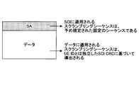
- the scrambling sequence applied to the SCI included in the SA (Scheduling Assignment) transmitted via the PSCCH is a fixed sequence defined in advance.
- the scrambling sequence applied to the data scheduled in the SA is derived based on the CRC (Cyclic Redundancy Check) of the SCI, and is independent of the ID for identifying the UE (User Equipment).
- the SA may be called SL-Scheduling ⁇ Grant.
- the PSCCH is blind-decoded.
- the associated PSSCH is decoded by the SCI obtained by blind decoding the PSCCH.
- the scrambling sequence applied to the SCI is a fixed sequence defined in the specification.
- the scrambling sequence applied to the data is derived based on the CRC of the SCI and is independent of the ID identifying the UE.
- V2X of NR it is required that a key performance indicator (KPI) related to a transmission rate or a delay is satisfied at a high level.
- KPI key performance indicator
- V2X of NR unicast, groupcast, and broadcast may be supported.
- any transmission type of unicast, groupcast or broadcast is used until packet decoding in the upper layer is successful. It was difficult to determine whether there was. Therefore, a problem occurs in QoS (Quality of Service) management of a lower layer link level in unicast or groupcast, for example, HARQ (Hybrid Automatic Repeat request) feedback, closed loop power control, CSI (Channel state information) reporting, and the like. there is a possibility. Therefore, in a lower layer such as a PHY layer, it is required to determine which transmission type is unicast, groupcast, or broadcast.
- QoS Quality of Service
- FIG. 4 is a diagram for explaining an example of scheduling.
- resources dedicated to each transmission type are previously allocated to PSCCH, PSSCH or PSDCH (Physical Sidelink Discovery Channel). There is a way to do that. That is, unicast, groupcast, and broadcast are transmitted using dedicated resources.
- the resource setting in which the PSCCH or PSSCH is arranged is common regardless of whether the transmission type is unicast, groupcast or broadcast, and the transmission type is determined by the SCI or data to be decoded. is there.
- this method it is not necessary to arrange a dedicated resource in advance depending on the transmission type, and flexible scheduling can be performed by sharing the resources with each transmission type.
- FIG. 5 is a diagram for describing an example (1) of side link transmission according to the embodiment of the present invention. An example of side link transmission using a method of determining the transmission type based on SCI or data to be decoded will be described.
- the SCI scrambling sequence for performing SA is derived based on the UE ID or RNTI (Radio network temporary identifier) of the UE that receives or transmits the SCI in the case of unicast.
- the SCI scrambling sequence for performing SA is derived based on the UE # ID or RNTI, the group ID or RNTI of the UE transmitting the SCI in the case of group cast.
- the SCI scrambling sequence for performing SA is set independently of the UE @ ID or RNTI, the group ID or RNTI, or is specified in advance.
- a scrambling sequence may be set using an upper layer signal (eg, MAC, RRC).
- a scrambling sequence may be set for each UE, group, and / or cell, or a scrambling sequence may be set for each of unicast, groupcast, and broadcast.
- the data scrambling sequence is derived based on the UE ID or RNTI of the UE that receives or transmits data.
- the data scrambling sequence is derived based on the UE # ID or RNTI of the UE transmitting the data and the group ID or RNTI in the case of groupcast.
- a scrambling sequence may be specified for each UE or / and group by an upper layer signal (eg, MAC, RRC).
- the data scrambling sequence is set independently of the UE ID or RNTI, the group ID or RNTI, or is predefined. Further, the data scrambling sequence may be common to the CSI scrambling sequence.
- a scrambling sequence may be set using an upper layer signal (eg, MAC, RRC).
- MAC Radio Resource Control
- a scrambling sequence may be set for each UE, group, and / or cell, or a scrambling sequence may be set for each of unicast, groupcast, and broadcast.
- FIG. 6 is a flowchart illustrating an example (1) of side link reception according to the embodiment of the present invention. An operation in which the user apparatus 20 receives the side link transmission illustrated in FIG. 5 will be described.
- step S11 the user apparatus 20 performs blind decoding of the SCI or data using a scrambling sequence based on the UE ID or RNTI. If the blind decoding is successful, the user device 20 can determine that the received SCI and data have been unicast and the destination. Here, when the SCI and the data are scrambled by the same scrambling sequence, the user apparatus 20 can decode the data by using the scrambling sequence capable of blindly decoding the SCI.
- step S12 the user device 20 performs blind decoding of the SCI or data using a scrambling sequence based on the group ID or RNTI. If the blind decoding is successful, the user device 20 can determine that the received SCI and data have been group-cast and the destination. Here, similarly to the unicast, when the SCI and the data are scrambled by the same scrambling sequence, the user apparatus 20 decodes the data by using the scrambling sequence capable of blindly decoding the SCI. Can be.
- step S13 the user apparatus 20 performs blind decoding using a scrambling sequence independent of the UE or group ID / RNTI defined or set for SCI or data for broadcast.
- the user device 20 can determine that the received SCI and data have been broadcast.
- the user apparatus 20 decodes the data using the scrambling sequence capable of blindly decoding the SCI. Can be.
- each of the steps S11, S12, and S13 may be executed in advance, or may be executed in any order.
- the priority of each step may be specified in the specification or set by the base station.
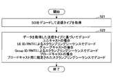
- FIG. 7 is a diagram illustrating an example (2) of side link transmission according to the embodiment of the present invention. An example of side link transmission using a method of determining the transmission type based on SCI or data to be decoded will be described.
- the SCI scrambling sequence for performing SA is set or specified in advance independently of the transmission type.
- the transmission type may be notified by the SCI.
- different transmission types may be associated with different SCI formats, and the transmission type may be determined based on the SCI format.
- the transmission type may be determined based on information included in the SCI (eg, MCS (Modulation Coding Scheme), RI (Rank Indicator)). For example, when performing higher-order modulation or multi-layer transmission, QoS control is required. If the MCS, RI, etc. are equal to or more than a certain value, the transmission type (eg, unicast, groupcast) for performing QoS control is determined. it can.
- MCS Modulation Coding Scheme
- RI Rank Indicator
- the data scrambling sequence is derived based on the UE ID or RNTI of the UE that receives or transmits data.
- the data scrambling sequence is derived based on the UE # ID or RNTI of the UE transmitting the data and the group ID or RNTI in the case of groupcast.
- the data scrambling sequence is set or predetermined independently of the UE or group ID or RNTI.
- a scrambling sequence may be set using an upper layer signal (eg, MAC, RRC).
- a scrambling sequence may be set for each UE, group, and / or cell, or a scrambling sequence may be set for each of unicast, groupcast, and broadcast.
- FIG. 8 is a flowchart illustrating an example (2) of side link reception according to the embodiment of the present invention. An operation in which the user apparatus 20 receives the side link transmission illustrated in FIG. 7 will be described.
- step S21 the user device 20 decodes the SCI to acquire the transmission type.
- the user device 20 acquires the transmission type based on the SCI format or other information included in the SCI.
- step S22 if the transmission type acquired in step S21 is unicast, the user equipment 20 decodes the data by a scrambling sequence based on the UE ID or RNTI. Further, when the transmission type acquired in step S21 is group cast, the user device 20 decodes the data by a scrambling sequence using a group ID or RNTI. If the transmission type obtained in step S21 is broadcast, the user apparatus 20 sets a scrambling sequence independent of the UE or group ID or RNTI for which SCI or data is defined or set for broadcast. Performs decoding.
- FIG. 9 is a diagram illustrating an example (3) of the side link transmission according to the embodiment of the present invention. An example of side link transmission using a method of determining the transmission type based on SCI or data to be decoded will be described.
- the SCI scrambling sequence for performing SA is set up or defined independently of the UE or group ID or RNTI.
- the data scrambling sequence is set independently of the UE or group ID or RNTI.
- the transmission type may be determined based on a destination ID included in a media access control (MAC) element (control element).
- MAC media access control
- the destination ID included in the MAC @ CE may be derived based on the UE @ ID or RNTI, in the case of groupcast, it may be derived based on the group ID or RNTI, and in the case of broadcast, It may be set independently of the UE or group ID or RNTI or may be predefined.
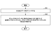
- FIG. 10 is a flowchart illustrating an example (3) of the side link reception according to the embodiment of the present invention. An operation in which the user apparatus 20 receives the side link transmission illustrated in FIG. 9 will be described.
- step S31 the user device 20 decodes the SCI and the data. Subsequently, in step S32, based on the MAC @ CE included in the decoded data, it is determined whether the transmission type is unicast, groupcast, or broadcast.
- the user device 20 may monitor the resource in which the PSCCH, PSSCH or PSDCH dedicated to unicast is allocated, assuming a scrambling sequence based on the UE ID or RNTI.
- UE @ ID or RNTI may be the ID or RNTI of the destination UE.
- the user device 20 may monitor the resource in which the PSCCH, PSSCH, or PSDCH dedicated to groupcast is allocated, assuming a scrambling sequence based on the group ID or RNTI.
- the user device 20 may monitor the resources in which the broadcast-dedicated PSCCH, PSSCH, or PSDCH is located, assuming a scrambling sequence that is independent of the UE or group ID or RNTI. For example, a scrambling sequence used in LTE Release 14 may be assumed.
- the user apparatus 20 can determine whether the side link communication is unicast, group cast, or broadcast in a lower layer such as a PHY layer. Therefore, the user apparatus 20 can suitably execute lower-layer link-level QoS management, such as HARQ feedback, closed-loop power control, and CSI feedback.
- lower-layer link-level QoS management such as HARQ feedback, closed-loop power control, and CSI feedback.
- the base station device 10 and the user device 20 include a function for implementing the above-described embodiment. However, each of the base station device 10 and the user device 20 may include only some of the functions in the embodiment.
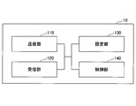
- FIG. 11 is a diagram illustrating an example of a functional configuration of the base station device 10.
- base station apparatus 10 includes transmitting section 110, receiving section 120, setting section 130, and control section 140.
- the functional configuration shown in FIG. 11 is only an example. As long as the operation according to the embodiment of the present invention can be executed, the names of the functional divisions and the functional units may be any.
- the transmission unit 110 has a function of generating a signal to be transmitted to the user device 20 and transmitting the signal wirelessly.
- the receiving unit 120 includes a function of receiving various signals transmitted from the user device 20 and acquiring, for example, information of a higher layer from the received signals.
- the transmitting unit 110 has a function of transmitting an NR-PSS, an NR-SSS, an NR-PBCH, a DL / UL control signal, and the like to the user device 20. Further, for example, the transmitting unit 110 transmits information indicating that another terminal is approaching the user device 20, and the receiving unit 120 receives terminal information from the user device 20.
- the setting unit 130 stores in the storage device the setting information set in advance and various setting information to be transmitted to the user device 20, and reads out the setting information from the storage device as needed.
- the content of the setting information is, for example, information related to the setting of the D2D communication.
- the control unit 140 performs the process related to the setting for the user device 20 to perform the D2D communication, as described in the embodiment.
- a function unit related to signal transmission in control unit 140 may be included in transmitting unit 110, and a function unit related to signal reception in control unit 140 may be included in receiving unit 120.
- FIG. 12 is a diagram illustrating an example of a functional configuration of the user device 20.
- the user device 20 includes a transmitting unit 210, a receiving unit 220, a setting unit 230, and a control unit 240.
- the functional configuration shown in FIG. 12 is only an example. As long as the operation according to the embodiment of the present invention can be executed, the names of the functional divisions and the functional units may be any.
- the transmission unit 210 creates a transmission signal from transmission data, and transmits the transmission signal wirelessly.
- the receiving unit 220 wirelessly receives various signals and obtains a higher-layer signal from the received physical-layer signal.
- the receiving section 220 has a function of receiving NR-PSS, NR-SSS, NR-PBCH, DL / UL / SL control signals, and the like transmitted from the base station apparatus 10.
- the transmission unit 210 transmits the PSCCH (Physical Sidelink Shared Channel), the PSSCH (Physical Sidelink Shared Channel), the PSDCH (Physical Sidelink Discovery Channel), and the PSBCH (Physical Sidelink Broadcast Channel) to another user device 20 as D2D communication. )
- the receiving unit 120 receives a PSCCH, a PSSCH, a PSDCH, a PSBCH, or the like from another user apparatus 20.
- the setting unit 230 stores various setting information received from the base station device 10 or the user device 20 by the receiving unit 220 in a storage device, and reads out the setting information from the storage device as needed.
- the setting unit 230 also stores preset setting information.
- the content of the setting information is, for example, information related to the setting of the D2D communication.
- the control unit 240 controls the D2D communication performed with another user device 20 as described in the embodiment. In addition, the control unit 240 performs transmission / reception processing based on the transmission type of the D2D communication.
- a function unit related to signal transmission in control unit 240 may be included in transmission unit 210, and a function unit related to signal reception in control unit 240 may be included in reception unit 220.
- each functional block may be realized by one device in which a plurality of elements are physically and / or logically combined, or two or more devices physically and / or logically separated from each other directly and And / or indirectly (for example, wired and / or wireless), and may be implemented by these multiple devices.
- both the base station device 10 and the user device 20 according to an embodiment of the present invention may function as a computer that performs processing according to the embodiment of the present invention.
- FIG. 13 is a diagram illustrating an example of a hardware configuration of a wireless communication device that is the base station device 10 or the user device 20 according to the embodiment of the present invention.
- Each of the above-described base station device 10 and user device 20 is physically a computer device including a processor 1001, a storage device 1002, an auxiliary storage device 1003, a communication device 1004, an input device 1005, an output device 1006, a bus 1007, and the like. It may be configured.
- the term “apparatus” can be read as a circuit, a device, a unit, or the like.
- the hardware configuration of the base station device 10 and the user device 20 may be configured to include one or more of the devices indicated by 1001 to 1006 illustrated in the drawing, or may be configured without including some devices. May be done.
- the functions of the base station device 10 and the user device 20 are performed by reading predetermined software (program) on hardware such as the processor 1001 and the storage device 1002, so that the processor 1001 performs an arithmetic operation. This is realized by controlling reading and / or writing of data in the storage device 1002 and the auxiliary storage device 1003.
- the processor 1001 controls the entire computer by operating an operating system, for example.
- the processor 1001 may be configured by a central processing unit (CPU: Central Processing Unit) including an interface with a peripheral device, a control device, an arithmetic device, a register, and the like.
- CPU Central Processing Unit
- the processor 1001 reads a program (program code), a software module, or data from the auxiliary storage device 1003 and / or the communication device 1004 to the storage device 1002, and executes various processes according to these.
- a program program that causes a computer to execute at least a part of the operation described in the above embodiment is used.
- the transmission unit 110, the reception unit 120, the setting unit 130, and the control unit 140 of the base station device 10 illustrated in FIG. 11 may be realized by a control program stored in the storage device 1002 and operated by the processor 1001.
- the transmission unit 210, the reception unit 220, the setting unit 230, and the control unit 240 of the user device 20 illustrated in FIG. Is also good.
- Processor 1001 may be implemented with one or more chips. Note that the program may be transmitted from a network via a telecommunication line.
- the storage device 1002 is a computer-readable recording medium, and is, for example, at least one of a ROM (Read Only Memory), an EPROM (Erasable Programmable ROM), an EEPROM (Electrically Erasable Programmable ROM), and a RAM (Random Access Memory). It may be configured.
- the storage device 1002 may be called a register, a cache, a main memory (main storage device), or the like.
- the storage device 1002 can store a program (program code), a software module, and the like that can be executed to execute the processing according to an embodiment of the present invention.
- the auxiliary storage device 1003 is a computer-readable recording medium, for example, an optical disk such as a CD-ROM (Compact Disc ROM), a hard disk drive, a flexible disk, a magneto-optical disk (for example, a compact disk, a digital versatile disk, Blu -Ray (registered trademark) disk), smart card, flash memory (eg, card, stick, key drive), floppy (registered trademark) disk, magnetic strip, or the like.
- the auxiliary storage device 1003 may be called an auxiliary storage device.
- the storage medium described above may be, for example, a database including the storage device 1002 and / or the auxiliary storage device 1003, a server, or any other appropriate medium.
- the communication device 1004 is hardware (transmitting / receiving device) for performing communication between computers via a wired and / or wireless network, and is also referred to as, for example, a network device, a network controller, a network card, a communication module, and the like.
- the transmitting unit 110 and the receiving unit 120 of the base station device 10 may be realized by the communication device 1004.
- the transmission unit 210 and the reception unit 220 of the user device 20 may be realized by the communication device 1004.
- the input device 1005 is an input device (for example, a keyboard, a mouse, a microphone, a switch, a button, a sensor, and the like) that receives an external input.
- the output device 1006 is an output device (for example, a display, a speaker, an LED lamp, and the like) that performs output to the outside. Note that the input device 1005 and the output device 1006 may have an integrated configuration (for example, a touch panel).
- the devices such as the processor 1001 and the storage device 1002 are connected by a bus 1007 for communicating information.
- the bus 1007 may be configured by a single bus, or may be configured by a different bus between the devices.
- the base station device 10 and the user device 20 are respectively a microprocessor, a digital signal processor (DSP: Digital Signal Processor), an ASIC (Application Specific Integrated Circuit), a PLD (Programmable Logic Device), an FPGA (Field Programmable Gate Array), and the like. And some or all of the functional blocks may be realized by the hardware.
- the processor 1001 may be implemented by at least one of these hardware.
- a receiving unit that receives control information and data through direct communication between terminals, and performs direct communication between terminals based on the control information or the data.
- a control unit for determining whether the broadcast is unicast, groupcast, or broadcast.
- the user device 20 can determine whether the side link communication is unicast, group cast, or broadcast in a lower layer such as a PHY layer. Further, the user apparatus 20 can suitably execute lower-layer link-level QoS management, such as HARQ feedback, closed-loop power control, and CSI feedback. That is, in direct communication between terminals, in direct communication between terminals, it is determined whether to transmit to a single terminal, transmit to a plurality of specific terminals, or transmit to a plurality of unspecified terminals. can do.
- lower-layer link-level QoS management such as HARQ feedback, closed-loop power control, and CSI feedback. That is, in direct communication between terminals, in direct communication between terminals, it is determined whether to transmit to a single terminal, transmit to a plurality of specific terminals, or transmit to a plurality of unspecified terminals. can do.
- the direct communication between the terminals is determined to be unicast, and the control information is a scrambling sequence based on a group identifier. If the decoding is successful using the above, the direct communication between the terminals is determined to be a group cast, and the control information is successfully decoded using a scrambling sequence independent of the identifier of the user apparatus or group. Alternatively, it may be determined that the terminal-to-terminal direct communication is a broadcast. With this configuration, the user device 20 can determine whether the side link communication is unicast, group cast, or broadcast in a lower layer such as a PHY layer.
- the decoding of the data may be performed using a scrambling sequence that successfully decodes the control information.
- the user device 20 can efficiently perform data decoding using the scrambling sequence that has successfully decoded the SCI.
- the direct communication between terminals included in the control information is unicast, groupcast or broadcast or the format of the control information. May be determined.
- the user device 20 can determine whether the side link communication is unicast, group cast, or broadcast in a lower layer such as a PHY layer.
- the direct communication between the terminals is determined to be unicast, decode the data using a scrambling sequence based on the identifier of the user equipment, and, the direct communication between the terminals was determined to be a group cast If the data is decoded using a scrambling sequence based on a group identifier, and if it is determined that the direct communication between terminals is broadcast, the data is scrambled independently of the user equipment or group identifier. Decoding may be performed using a ring sequence. With this configuration, the user apparatus 20 can select an appropriate scrambling sequence based on the result of determining whether the side link communication is unicast, group cast, or broadcast, and decode data efficiently. Can be.
- the user device 20 can determine whether the side link communication is unicast, group cast, or broadcast in a lower layer such as a MAC layer.
- the operation of a plurality of functional units may be physically performed by one component, or the operation of one functional unit may be physically performed by a plurality of components.
- the order of the processing may be changed as long as there is no contradiction.
- the base station device 10 and the user device 20 have been described using a functional block diagram for convenience of processing description, such a device may be realized by hardware, software, or a combination thereof.
- the software operated by the processor of the base station apparatus 10 according to the embodiment of the present invention and the software operated by the processor of the user apparatus 20 according to the embodiment of the present invention are a random access memory (RAM), a flash memory, and a read memory, respectively.
- the data may be stored in a dedicated memory (ROM), EPROM, EEPROM, register, hard disk (HDD), removable disk, CD-ROM, database, server, or any other suitable storage medium.
- the notification of information is not limited to the aspect / embodiment described in this specification, and may be performed by another method.
- the notification of information includes physical layer signaling (for example, DCI (Downlink Control Information), UCI (Uplink Control Information)), upper layer signaling (for example, RRC (Radio Resource Control) signaling, MAC (Medium Access Control) signaling, RRC signaling may be implemented by broadcast information (MIB (Master Information Block), SIB (System Information Block)), other signals, or a combination thereof, and RRC signaling may be referred to as an RRC message.
- a connection setup (RRC (Connection Setup) message, an RRC connection reconfiguration (RRC Connection Reconfiguration) message, or the like may be used.
- Each aspect / embodiment described in this specification includes LTE (Long Term Evolution), LTE-A (LTE-Advanced), SUPER 3G, IMT-Advanced, 4G, 5G, FRA (Future Radio Access), W-CDMA.
- LTE Long Term Evolution
- LTE-A Long Term Evolution-Advanced
- SUPER 3G IMT-Advanced
- 4G 5G
- FRA Full Radio Access
- W-CDMA Wideband
- GSM registered trademark
- CDMA2000 Code Division Multiple Access 2000
- UMB User Mobile Broadband
- IEEE 802.11 Wi-Fi
- IEEE 802.16 WiMAX
- IEEE 802.20 UWB (Ultra-WideBand
- the present invention may be applied to a system using Bluetooth (registered trademark), another appropriate system, and / or a next-generation system extended based on the system.
- the specific operation described as being performed by the base station device 10 in this specification may be performed by an upper node (upper node) in some cases.
- an upper node In a network including one or a plurality of network nodes (network @ nodes) including the base station device 10, various operations performed for communication with the user device 20 are different from the base station device 10 and / or the base station device 10. It is clear that this can be done by other network nodes (for example, but not limited to MME or S-GW etc.).
- MME Mobility Management Entity
- the user equipment 20 may be provided by one of ordinary skill in the art to a subscriber station, mobile unit, subscriber unit, wireless unit, remote unit, mobile device, wireless device, wireless communication device, remote device, mobile subscriber station, access terminal, mobile terminal, It may also be called a wireless terminal, remote terminal, handset, user agent, mobile client, client, or some other suitable term.
- Base station device 10 may also be referred to by those skilled in the art as NB (NodeB), eNB (evolved NodeB), gNB (next generation eNB), base station (Base Station), or some other suitable terminology.
- NB NodeB
- eNB evolved NodeB
- gNB next generation eNB
- Base Station Base station device 10 may also be referred to by those skilled in the art as NB (NodeB), eNB (evolved NodeB), gNB (next generation eNB), base station (Base Station), or some other suitable terminology.
- determining may encompass a wide variety of operations. “Judgment” and “decision” are, for example, judgment (judging), calculation (computing), processing (processing), deriving (investigating), and investigating (looking up) (for example, a table). , A search in a database or another data structure), ascertaining, etc. may be considered as “determined”, “determined”, etc. Also, “determining” and “determining” refer to receiving (eg, receiving information), transmitting (eg, transmitting information), input (input), output (output), access (Accessing) (e.g., accessing data in the memory) may be regarded as “determined” or "determined”.
- judgment and “decision” mean that resolving, selecting, choosing, choosing, establishing, comparing, etc. are regarded as “judgment” and “determined”. May be included. In other words, “judgment” and “decision” may include deeming any operation as “judgment” and “determined”.
- the SCI is an example of control information.
- UE @ ID or RNTI is an example of an identifier of a user apparatus.
- the group ID or RNTI is an example of a group identifier.
- MAC @ CE is an example of a MAC control element.
Landscapes
- Engineering & Computer Science (AREA)
- Computer Networks & Wireless Communication (AREA)
- Signal Processing (AREA)
- Mobile Radio Communication Systems (AREA)
Abstract
Dispositif d'utilisateur comprenant: une unité de réception qui reçoit des informations de commande et des données, via une communication directe inter-terminaux; et une unité de commande, qui, sur la base des informations de commande ou des données, détermine si la communication directe inter-terminaux est une monodiffusion, une diffusion en groupe ou une diffusion générale.
Priority Applications (5)
| Application Number | Priority Date | Filing Date | Title |
|---|---|---|---|
| CN201880096262.9A CN112514518B (zh) | 2018-08-09 | 2018-08-09 | 用户装置 |
| PCT/JP2018/029986 WO2020031348A1 (fr) | 2018-08-09 | 2018-08-09 | Dispositif d'utilisateur |
| EP18929568.6A EP3836730A4 (fr) | 2018-08-09 | 2018-08-09 | Dispositif d'utilisateur |
| US17/265,365 US12082083B2 (en) | 2018-08-09 | 2018-08-09 | Terminal and communication method for inter-device direct communication |
| JP2020535444A JP7179856B2 (ja) | 2018-08-09 | 2018-08-09 | 端末及び通信方法 |
Applications Claiming Priority (1)
| Application Number | Priority Date | Filing Date | Title |
|---|---|---|---|
| PCT/JP2018/029986 WO2020031348A1 (fr) | 2018-08-09 | 2018-08-09 | Dispositif d'utilisateur |
Publications (1)
| Publication Number | Publication Date |
|---|---|
| WO2020031348A1 true WO2020031348A1 (fr) | 2020-02-13 |
Family
ID=69415400
Family Applications (1)
| Application Number | Title | Priority Date | Filing Date |
|---|---|---|---|
| PCT/JP2018/029986 Ceased WO2020031348A1 (fr) | 2018-08-09 | 2018-08-09 | Dispositif d'utilisateur |
Country Status (5)
| Country | Link |
|---|---|
| US (1) | US12082083B2 (fr) |
| EP (1) | EP3836730A4 (fr) |
| JP (1) | JP7179856B2 (fr) |
| CN (1) | CN112514518B (fr) |
| WO (1) | WO2020031348A1 (fr) |
Families Citing this family (4)
| Publication number | Priority date | Publication date | Assignee | Title |
|---|---|---|---|---|
| EP3955481A4 (fr) * | 2019-04-12 | 2022-11-02 | Beijing Xiaomi Mobile Software Co., Ltd. | Procédé de traitement d'embrouillage, procédé de traitement de désembrouillage et dispositif |
| US12156178B2 (en) * | 2019-04-12 | 2024-11-26 | Lg Electronics Inc. | Method and apparatus for transmitting SCI in NR V2X groupcast communication |
| US11425552B2 (en) * | 2019-08-09 | 2022-08-23 | Electronics And Telecommunications Research Institute | Method of connection control for direct communication between terminals, and apparatus therefor |
| US12526784B2 (en) | 2021-12-07 | 2026-01-13 | Qualcomm Incorporated | Scrambling sidelink control information in sidelink communication |
Citations (2)
| Publication number | Priority date | Publication date | Assignee | Title |
|---|---|---|---|---|
| JP2016532334A (ja) * | 2013-11-22 | 2016-10-13 | 富士通株式会社 | 装置間データチャネルシグナリング |
| JP2017501610A (ja) * | 2013-10-28 | 2017-01-12 | エルジー エレクトロニクス インコーポレイティド | 無線通信システムにおける装置対装置端末の信号送受信方法及び装置 |
Family Cites Families (20)
| Publication number | Priority date | Publication date | Assignee | Title |
|---|---|---|---|---|
| US8848728B1 (en) * | 2010-04-08 | 2014-09-30 | Marvell Israel (M.I.S.L) Ltd. | Dynamic load balancing switch architecture |
| KR101725345B1 (ko) * | 2010-12-09 | 2017-04-11 | 에스케이텔레콤 주식회사 | 무선 랜에서 브로드캐스팅/멀티캐스팅 전송과 유니캐스팅 전송을 혼용한 방송 패킷 재전송 시스템 및 방법 |
| JP5902916B2 (ja) * | 2011-11-07 | 2016-04-13 | シャープ株式会社 | 基地局、端末、通信システムおよび通信方法 |
| JP2014096777A (ja) * | 2012-11-12 | 2014-05-22 | Ntt Docomo Inc | 無線通信方法、無線通信システム、無線基地局及びユーザ端末 |
| WO2014092370A1 (fr) * | 2012-12-14 | 2014-06-19 | 엘지전자 주식회사 | Procédé d'ordonnancement pour communication directe entre terminaux dans un système de radiocommunications, et dispositif à cet effet |
| US9456330B2 (en) * | 2013-08-09 | 2016-09-27 | Alcatel Lucent | Two-stage device-to-device (D2D) discovery procedures |
| WO2015063186A1 (fr) * | 2013-10-31 | 2015-05-07 | Telefonaktiebolaget L M Ericsson (Publ) | Procédé et dispositif pour une communication de dispositif à dispositif (d2d) dans un réseau radio cellulaire |
| KR102078424B1 (ko) | 2014-11-07 | 2020-02-19 | 이노스카이 주식회사 | 무선 통신 시스템에서 단말간 통신채널을 전송하는 장치 및 방법 |
| US10397795B2 (en) * | 2015-01-30 | 2019-08-27 | Mediatek Inc. | Frame structure and data mapping for license assisted access |
| CN107580788B (zh) * | 2015-02-26 | 2021-10-15 | 三星电子株式会社 | 用于在单播设备到设备(d2d)通信和组播d2d通信之间区分的方法 |
| WO2016136493A1 (fr) * | 2015-02-27 | 2016-09-01 | 京セラ株式会社 | Station de base et terminal sans fil |
| CN107432011A (zh) * | 2015-03-31 | 2017-12-01 | 株式会社Ntt都科摩 | 用户装置以及控制信息发送方法 |
| US10027729B2 (en) * | 2015-05-22 | 2018-07-17 | Qualcomm Incorporated | Unicast support in prose direct device-to-device communication |
| WO2017023128A1 (fr) * | 2015-08-04 | 2017-02-09 | 엘지전자(주) | Procédé permettant de recevoir un message de diffusion/multidiffusion dans un dispositif de communication sans fil et dispositif s'y rapportant |
| US11398851B2 (en) * | 2016-02-08 | 2022-07-26 | Sony Group Corporation | Operating a cellular MIMO system |
| US20180035435A1 (en) * | 2016-07-27 | 2018-02-01 | Qualcomm Incorporated | Mechanisms for interference management of multi-tti sidelink-centric subframes in wireless communication |
| CN109804683B (zh) | 2016-08-11 | 2023-08-04 | Lg电子株式会社 | 在无线通信系统中终端向另一终端发送数据的方法 |
| JP7039864B2 (ja) * | 2017-05-18 | 2022-03-23 | ソニーグループ株式会社 | 送信装置、受信装置、方法及び記録媒体 |
| WO2019195505A1 (fr) * | 2018-04-04 | 2019-10-10 | Idac Holdings, Inc. | Signalisation d'informations de commande, et procédure pour des communications new radio (nr) de véhicule à tout (v2x) |
| EP4284114B1 (fr) * | 2018-04-05 | 2025-07-16 | Telefonaktiebolaget LM Ericsson (publ) | Informations de commande de liaison latérale multi-étage |
-
2018
- 2018-08-09 CN CN201880096262.9A patent/CN112514518B/zh active Active
- 2018-08-09 WO PCT/JP2018/029986 patent/WO2020031348A1/fr not_active Ceased
- 2018-08-09 US US17/265,365 patent/US12082083B2/en active Active
- 2018-08-09 JP JP2020535444A patent/JP7179856B2/ja active Active
- 2018-08-09 EP EP18929568.6A patent/EP3836730A4/fr active Pending
Patent Citations (2)
| Publication number | Priority date | Publication date | Assignee | Title |
|---|---|---|---|---|
| JP2017501610A (ja) * | 2013-10-28 | 2017-01-12 | エルジー エレクトロニクス インコーポレイティド | 無線通信システムにおける装置対装置端末の信号送受信方法及び装置 |
| JP2016532334A (ja) * | 2013-11-22 | 2016-10-13 | 富士通株式会社 | 装置間データチャネルシグナリング |
Non-Patent Citations (4)
| Title |
|---|
| 3GPP TR 22.886, March 2017 (2017-03-01) |
| 3GPP TS 36.211, June 2018 (2018-06-01) |
| See also references of EP3836730A4 |
| ZTE: "Control channel design for D2D communication", 3GPP TSG-RAN WG1#74B R1-134307, 28 September 2013 (2013-09-28), XP050717451 * |
Also Published As
| Publication number | Publication date |
|---|---|
| US12082083B2 (en) | 2024-09-03 |
| CN112514518B (zh) | 2024-04-26 |
| EP3836730A4 (fr) | 2022-05-11 |
| US20210297830A1 (en) | 2021-09-23 |
| CN112514518A (zh) | 2021-03-16 |
| EP3836730A1 (fr) | 2021-06-16 |
| JPWO2020031348A1 (ja) | 2021-08-10 |
| JP7179856B2 (ja) | 2022-11-29 |
Similar Documents
| Publication | Publication Date | Title |
|---|---|---|
| JP7223004B2 (ja) | 端末及び通信方法 | |
| AU2018455187B2 (en) | User device and communication device | |
| US12063603B2 (en) | User equipment and base station apparatus | |
| WO2020049669A1 (fr) | Dispositif utilisateur, et dispositif station de base | |
| WO2020136855A1 (fr) | Dispositif d'utilisateur | |
| JP7219768B2 (ja) | 端末、無線通信システム及び通信方法 | |
| WO2020136854A1 (fr) | Dispositif d'utilisateur | |
| JP7132334B2 (ja) | 端末及び通信方法 | |
| KR20210112335A (ko) | 유저장치, 및 피드백 정보 송신 방법 | |
| WO2020053965A1 (fr) | Équipement d'utilisateur et dispositif de station de base | |
| WO2020021640A1 (fr) | Dispositif utilisateur et dispositif de station de base | |
| WO2020144825A1 (fr) | Équipement utilisateur et dispositif de station de base | |
| WO2020136851A1 (fr) | Dispositif utilisateur | |
| JP7179856B2 (ja) | 端末及び通信方法 | |
| JP7408668B2 (ja) | 端末及び通信方法 | |
| WO2020222266A1 (fr) | Dispositif utilisateur | |
| WO2020059132A1 (fr) | Dispositif utilisateur et dispositif de station de base | |
| WO2020179129A1 (fr) | Dispositif utilisateur | |
| WO2020054044A1 (fr) | Appareil d'utilisateur et appareil de station de base | |
| WO2020174772A1 (fr) | Dispositif utilisateur et procédé de communication | |
| WO2020039515A1 (fr) | Dispositif d'utilisateur et dispositif de station de base | |
| WO2020003367A1 (fr) | Dispositif d'utilisateur et appareil de station de base |
Legal Events
| Date | Code | Title | Description |
|---|---|---|---|
| 121 | Ep: the epo has been informed by wipo that ep was designated in this application |
Ref document number: 18929568 Country of ref document: EP Kind code of ref document: A1 |
|
| ENP | Entry into the national phase |
Ref document number: 2020535444 Country of ref document: JP Kind code of ref document: A |
|
| NENP | Non-entry into the national phase |
Ref country code: DE |
|
| ENP | Entry into the national phase |
Ref document number: 2018929568 Country of ref document: EP Effective date: 20210309 |