WO2020031564A1 - Dispositif de poignée externe pour portières de véhicule - Google Patents
Dispositif de poignée externe pour portières de véhicule Download PDFInfo
- Publication number
- WO2020031564A1 WO2020031564A1 PCT/JP2019/026456 JP2019026456W WO2020031564A1 WO 2020031564 A1 WO2020031564 A1 WO 2020031564A1 JP 2019026456 W JP2019026456 W JP 2019026456W WO 2020031564 A1 WO2020031564 A1 WO 2020031564A1
- Authority
- WO
- WIPO (PCT)
- Prior art keywords
- handle
- slit
- handle body
- base member
- vehicle door
- Prior art date
- Legal status (The legal status is an assumption and is not a legal conclusion. Google has not performed a legal analysis and makes no representation as to the accuracy of the status listed.)
- Ceased
Links
Images


Classifications
-
- E—FIXED CONSTRUCTIONS
- E05—LOCKS; KEYS; WINDOW OR DOOR FITTINGS; SAFES
- E05B—LOCKS; ACCESSORIES THEREFOR; HANDCUFFS
- E05B81/00—Power-actuated vehicle locks
- E05B81/54—Electrical circuits
- E05B81/64—Monitoring or sensing, e.g. by using switches or sensors
- E05B81/76—Detection of handle operation; Detection of a user approaching a handle; Electrical switching actions performed by door handles
- E05B81/77—Detection of handle operation; Detection of a user approaching a handle; Electrical switching actions performed by door handles comprising sensors detecting the presence of the hand of a user
-
- B—PERFORMING OPERATIONS; TRANSPORTING
- B60—VEHICLES IN GENERAL
- B60J—WINDOWS, WINDSCREENS, NON-FIXED ROOFS, DOORS, OR SIMILAR DEVICES FOR VEHICLES; REMOVABLE EXTERNAL PROTECTIVE COVERINGS SPECIALLY ADAPTED FOR VEHICLES
- B60J5/00—Doors
- B60J5/04—Doors arranged at the vehicle sides
-
- E—FIXED CONSTRUCTIONS
- E05—LOCKS; KEYS; WINDOW OR DOOR FITTINGS; SAFES
- E05B—LOCKS; ACCESSORIES THEREFOR; HANDCUFFS
- E05B79/00—Mounting or connecting vehicle locks or parts thereof
- E05B79/02—Mounting of vehicle locks or parts thereof
- E05B79/06—Mounting of handles, e.g. to the wing or to the lock
-
- E—FIXED CONSTRUCTIONS
- E05—LOCKS; KEYS; WINDOW OR DOOR FITTINGS; SAFES
- E05B—LOCKS; ACCESSORIES THEREFOR; HANDCUFFS
- E05B85/00—Details of vehicle locks not provided for in groups E05B77/00 - E05B83/00
- E05B85/10—Handles
- E05B85/14—Handles pivoted about an axis parallel to the wing
- E05B85/16—Handles pivoted about an axis parallel to the wing a longitudinal grip part being pivoted at one end about an axis perpendicular to the longitudinal axis of the grip part
Definitions
- the present invention provides a handle main body having a housing concave portion for housing an electronic component and having a substantially U-shaped cross section in which the side opposite to the outer panel of the vehicle door is opened, and an outer surface side of the vehicle door.
- a handle cover that covers the handle body from the outside so as to constitute the operation handle to be arranged together with the handle body, a base member fixed to the vehicle door, and one end in the longitudinal direction of the handle body are provided continuously.
- a support arm protruding into the outer panel and rotatably supported by the base member via a support shaft. The support arm is housed in the housing recess at the one end and the support arm of the handle body.
- the present invention relates to an out-handle device for a vehicle door in which a slit through which a harness connected to the electronic component is inserted is formed.
- Patent Document 1 discloses an out-handle device for a vehicle door in which a slit for easily inserting a harness connected to an electronic component housed in a housing recess of a handle body is provided in the handle body and the support arm. ing.
- the present invention has been made in view of such circumstances, and has a slit for facilitating the work of assembling a harness, but is capable of preventing a decrease in strength while avoiding an increase in the number of parts. It is an object to provide a door out-handle device.
- the present invention provides a handle body having a housing concave portion for housing an electronic component and having a substantially U-shaped cross-section with an opening on a side opposite to an outer panel of a vehicle door, A handle cover that covers the handle body from outside by configuring an operation handle disposed on the outer surface side of the vehicle door with the handle body, a base member fixed to the vehicle door, A support arm connected to one end in the longitudinal direction, protruding into the outer panel, and rotatably supported by the base member via a support shaft; and the one end and the support of the handle main body.
- a slit is formed in the arm, through which a harness connected to the electronic component housed in the housing recess is inserted.
- the Ndorukaba abutting or close to the both sides of the slit, first reinforcing portion is fitted into the slit so as to face to the first, characterized in that provided integrally.
- the base member is provided integrally with a second reinforcing portion that is fitted into the slit so as to abut, approach, or face both side surfaces of the slit. Is a second feature.
- the present invention enables the first reinforcing portion to push the harness in the slit so as to position the harness at a regular position.
- a third feature is that they are provided integrally.
- the first base member 18 of the embodiment corresponds to the base member of the present invention
- the electronic component integrated unit 38 of the embodiment corresponds to the electronic component of the present invention
- the first reinforcing portion provided integrally with the handle cover is fitted into the slit such that the first reinforcing portion comes into contact with, close to, or opposes both side surfaces of the slit.
- the strength of the handle body and the support arm at the portion where the slit for increasing the strength is provided can be prevented while avoiding an increase in the number of parts.
- the second reinforcing portion provided integrally with the base member is fitted into the slit such that the second reinforcing portion comes into contact with, close to, or faces both sides of the slit. It is possible to more reliably prevent the strength of the handle main body and the support arm from being reduced at the part where the handle is provided.
- the harness since the harness can be pushed into the slit and positioned at a regular position by the first reinforcing portion, the harness can be positioned between the handle body and the support arm and the first reinforcing portion. Of the harness can be prevented from occurring.
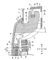
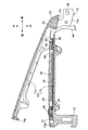
- FIG. 2 is a sectional view taken along line 2-2 of FIG. 1. It is an exploded perspective view of an out-handle device.
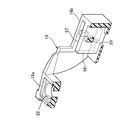
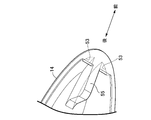
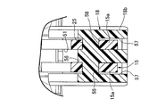
- FIG. 4 is an enlarged sectional view taken along line 4-4 of FIG. 1. It is a longitudinal section perspective view of a base member. It is the perspective view which looked at one end of the handle cover from the handle body side. It is a longitudinal cross-sectional view which shows the state at the time of assembling the handle cover to the handle main body.
- FIG. 8 is a sectional view taken along line 8-8 of FIG. 4.
- An operation handle 12 extending in the direction (the left-right direction in FIGS. 1 and 2) is rotatably mounted.
- the operation handle 12 is formed of a hard synthetic resin, extends in the front-rear direction of the vehicle, and is disposed on the outer surface side of the outer panel 11.
- the handle body 13 has a substantially U-shaped cross-sectional shape opened to the side opposite to the outer panel 11 and extends in the front-rear direction of the vehicle, and has one end along its longitudinal direction.
- a substantially L-shaped support arm 15 which protrudes into the outer panel 11 is integrally provided at a front end portion (right end portion in FIGS. 1 and 2), and the other end of the handle main body 13 is provided.
- a connecting arm 16 that protrudes into the outer panel 11 is integrally provided at the rear end.
- the outer panel 11 has a curved portion 11a that forms a recess 17 that is inserted between the support arm 15 and the connecting arm 16 so that a hand of a vehicle user holding the operation handle 12 can be inserted. It is provided so as to swell inward in the width direction.
- a first sheet member 20 having a thin plate shape is interposed between the vehicle door D and the outer surface of the outer panel 11 at a position where the recess 17 is sandwiched between the vehicle doors D in the front-rear direction of the vehicle.
- a second base member 19 with a thin plate-shaped second sheet member 21 interposed between the base member 18 and the outer surface of the outer panel 11 is fixed.
- the first base member 18 is disposed forward of the recess 17 in the vehicle longitudinal direction, and the first seat member 20 is attached to the outer panel 11.
- a mounting portion 18a disposed outside of the outer panel 11 between the outer surface of the outer panel 11 and a substantially L-shaped portion which is integrally connected to the mounting portion 18a and inserted into the outer panel 11 And a handle-shaped support portion 18b.
- a fitting hole 22 is formed in the attached portion 18a, and a first nut 23 engaged with the attached portion 18a from the side opposite to the outer panel 11 is fitted in the fitting hole 22.
- the first base member 18 is fixed to the outer panel 11 of the vehicle door D by screwing a first bolt 24 inserted into the outer panel 11 to the first nut 23. Is done.
- a support shaft 25 is provided integrally with the handle support portion 18b, and a tip end of the support arm 15 is rotatably supported by the support shaft 25.
- the second base member 19 is disposed rearward of the recess 17 in the vehicle front-rear direction, and the second base member 19 is disposed between the second base member 19 and the outer surface of the outer panel 11.
- a base member main portion 19a disposed outside the outer panel 11 with the sheet member 21 interposed therebetween; a mounted portion 19b integrally provided with the base member main portion 19a and extending inward of the outer panel 11; And a guide portion 19c.
- An end wall 26 that constitutes a rear end of the vehicle door D along the vehicle front-rear direction is coupled to the outer panel 11, and a front end of the attached portion 19b facing the end wall 26 includes the end
- a second nut 27 is press-fitted from the wall 26 side, and a second bolt 28 inserted into the end wall 26 is screwed into the second nut 27 to be tightened. 19 is fixed to the end wall 26 of the vehicle door D.
- a recess 29 is formed in the front half of the base member main portion 19a in the front-rear direction of the vehicle to receive the other end, that is, the rear end of the operation handle 12 without the operation handle 12 being operated.
- the outer surface of the member main portion 19a is formed so as to smoothly connect to the outer surface of the handle cover 14 of the operation handle 12 in a state where the rear end of the operation handle 12 is received in the recess 29.
- An insertion hole 30 for inserting the connection arm 16 is formed in the recess 29, and the guide portion 19 c guides the connection arm 16 inserted into the insertion hole 30 so that the base member It is integrally connected to the portion 19a.
- the connecting arm 16 is connected to a latch mechanism (not shown).
- the latch mechanism turns the vehicle door D closed.
- the vehicle door D can be opened by operating the operation handle 12.
- the handle main body 13 is integrally provided with a partition wall 31 disposed at a position spaced forward from an end wall 13a at a rear end along the vehicle front-rear direction.
- An accommodating recess 33 is formed in the handle body 13 and opens toward the handle cover 14.
- a touch sensor 35 for detecting that a vehicle user swings on the operation handle 12 is provided on the back side of the substrate 34.
- an electronic component integrated unit 38 as an electronic component in which a detection circuit (not shown), a tact switch 36 and an antenna 37 are disposed on the front side of the substrate 34 is accommodated in the accommodation recess 33.
- the tact switch 36 is for confirming the locking intention of the vehicle user by pressing the switch button 39 by the vehicle user, and the handle cover 14 has an opening 40 facing the switch button 39. Provided.
- Positioning recesses 41 are formed at two places on both sides of the board 34 spaced apart in the vehicle front-rear direction. Positioning protrusions 42 protruding from the upper and lower sides of the housing recess 34 are integrally formed with the handle body 13. The positioning protrusions 42 are fitted into the positioning recesses 41, respectively. The position of the electronic component integrated unit 38 in 33 is determined.
- a connector 45 for connecting a plurality of conductive wires 43 is attached to an end of the substrate 34 opposite to the partition wall 31, and the conductive wires 43 extend from the connector 45 in the vehicle front-rear direction. It is inserted through a rubber grommet 46 attached to the handle body 13 at a position spaced forward.
- a mounting groove 47 is formed on the inner surface of the handle body 13 for mounting the grommet 46, and the upper and lower side edges of the grommet 46 and the inner edge along the vehicle width direction are fitted into the mounting groove 47. Then, the grommet 46 is attached to the handle body 13.
- the housing recess 33 is formed in the handle main body 13 between the partition wall 31 and the grommet 46, and the electronic component integrated unit 38 is positioned in the housing recess 33.
- the housing recess 33 is filled with a potting agent 49 so that the electronic component integrated unit 38 is buried.
- a plurality of the conductive wires 43 are arranged as a harness 44 on the opposite side of the grommet 46 from the housing recess 33, and the harness 44 is connected to one end (the front end in this embodiment) of the handle body 13 and the support arm. 5 is led out to the outside through a slit 51 provided in the same.
- the slit 51 is formed at the center in the width direction of the support arm 15. By the formation of the slit 51, the support arm 15 becomes a pair of divided arm portions 15 a, 15 a arranged on both sides of the slit 51.
- the handle cover 14 is fastened to the handle body 13 so as to cover the handle body 13 from the outside, and is disposed on both sides of the slit 51 at the front end of the handle body 13.
- a pair of engaging projections 52 projecting forward in the vehicle front-rear direction are provided.
- the handle cover 14 is formed with a locking recess 53 to which the engaging projection 52 is engaged so as to open rearward in the vehicle front-rear direction.
- the handle cover 14 has a rear end wall 14 a facing the rear end wall 13 a of the handle main body 13 from behind, and the rear end wall 14 a of the handle cover 14 is The handle member 13 is fastened to the rear end wall 13a by a screw member 54.
- the handle cover 14 is integrally provided with a first reinforcing portion 55 that is fitted into the slit 51 so as to abut, approach, or face both sides of the slit 51.
- the first reinforcing portion 55 provided at the front end of the handle cover 14 so as to be disposed between the pair of locking concave portions 53 is fitted into the slit 51.
- the first reinforcing portion 55 engages the handle projection 14 with the engaging projection 52 at the front end of the handle body 13 with the locking recess 53 at the front end.
- the harness 44 in the slit 51 is properly adjusted. Will be pushed so as to be positioned at the position.
- the first base member 18 is integrally provided with a second reinforcing portion 56 that is fitted into the slit 51 so as to abut, approach, or face both sides of the slit 51. Is provided.
- the second reinforcing portion 56 is formed with a pair of insertion recesses 57 on both sides for inserting front ends of the pair of split arm portions 15 constituting the support arm 15, so that the first base member 18 is formed.
- the support shaft 25 is provided integrally with the handle support portion 18b so as to straddle the insertion recess 57, and the split arm portion of the support arm 15 is provided on the handle support portion 18b. At the front end of 15a, fitting recesses 58 for fitting the support shafts 25 are formed.
- a first end (a front end in this embodiment) of a handle cover 14 that constitutes the operation handle 12 together with the handle body 13 and a first door fixed to the vehicle door D are provided.
- the support arm 15 is rotatably supported by the base member 18 via the support shaft 25 and is connected to the front end of the handle body 13.
- the support arm 15 is housed in the housing recess 33 in the handle body 13.
- a slit 51 through which the harness 44 connected to the electronic component integrated unit 38 is inserted is formed, and the handle cover 14 is fitted into the slit 51 so as to be in contact with, close to, or opposed to both side surfaces of the slit 51.
- the hang at the portion where the slit 51 for improving the workability of assembling the harness 44 is provided is provided.
- the reduction in strength of the reel body 13 and the support arm 15 can be prevented while avoiding increase in the number of parts.
- the first reinforcing portion 55 is provided integrally with the handle cover 14 so that the harness 44 in the slit 51 can be pushed in so as to be positioned at a regular position, the first reinforcing portion 55 The harness 44 can be pushed into the position 51 to be positioned at a regular position, and the harness 44 can be prevented from being caught between the handle body 13 and the support arm 15 and the first reinforcing portion 55. .
- first base member 18 is integrally provided with the second reinforcing portion 56 which is fitted into the slit 51 so as to be in contact with, close to, or opposed to both side surfaces of the slit 51, so that the slit 51 is provided. It is possible to more reliably prevent the strength of the handle body 13 and the support arm 15 from being reduced at the portion where the power is applied.
Landscapes
- Engineering & Computer Science (AREA)
- Mechanical Engineering (AREA)
- Lock And Its Accessories (AREA)
Abstract
La présente invention concerne un dispositif de poignée externe pour des portières de véhicule, qui comprend un corps de poignée présentant un évidement de réception, un couvercle de poignée cachant le corps de poignée de l'extérieur, un élément de base fixé à une portière de véhicule et un bras de support raccordé à une extrémité du corps de poignée dans la direction longitudinale et soutenu en rotation par l'élément de base par l'intermédiaire d'une broche, une fente étant formée sur une extrémité du corps de poignée et du bras de support pour permettre à un harnais connecté à un composant électronique reçu dans l'évidement de réception d'être inséré ; bien qu'une fente soit prévue de manière à simplifier le travail d'assemblage pour le harnais, il est possible d'empêcher une diminution de la résistance tout en évitant une augmentation du nombre de composants. Une première unité de renforcement (55) qui est ajustée dans la fente (51) est formée d'un seul tenant avec le couvercle de poignée (14) de manière à faire face aux deux faces latérales de la fente (51) tout en étant en butée contre cette dernière ou proche de cette dernière.
Priority Applications (2)
| Application Number | Priority Date | Filing Date | Title |
|---|---|---|---|
| CN201980044202.7A CN112384671A (zh) | 2018-08-10 | 2019-07-03 | 车门的外把手装置 |
| US17/260,135 US11692378B2 (en) | 2018-08-10 | 2019-07-03 | External handle device for vehicle doors |
Applications Claiming Priority (2)
| Application Number | Priority Date | Filing Date | Title |
|---|---|---|---|
| JP2018151332A JP6916764B2 (ja) | 2018-08-10 | 2018-08-10 | 車両用ドアのアウトハンドル装置 |
| JP2018-151332 | 2018-08-10 |
Publications (1)
| Publication Number | Publication Date |
|---|---|
| WO2020031564A1 true WO2020031564A1 (fr) | 2020-02-13 |
Family
ID=69415487
Family Applications (1)
| Application Number | Title | Priority Date | Filing Date |
|---|---|---|---|
| PCT/JP2019/026456 Ceased WO2020031564A1 (fr) | 2018-08-10 | 2019-07-03 | Dispositif de poignée externe pour portières de véhicule |
Country Status (4)
| Country | Link |
|---|---|
| US (1) | US11692378B2 (fr) |
| JP (1) | JP6916764B2 (fr) |
| CN (1) | CN112384671A (fr) |
| WO (1) | WO2020031564A1 (fr) |
Cited By (1)
| Publication number | Priority date | Publication date | Assignee | Title |
|---|---|---|---|---|
| EP4151821A1 (fr) * | 2021-08-31 | 2023-03-22 | HUF Hülsbeck & Fürst GmbH & Co. KG | Ensemble de poignée pour porte de véhicule automobile |
Families Citing this family (6)
| Publication number | Priority date | Publication date | Assignee | Title |
|---|---|---|---|---|
| DE102018117954A1 (de) * | 2018-07-25 | 2020-01-30 | Huf Hülsbeck & Fürst Gmbh & Co. Kg | Kraftfahrzeuggriff |
| US20220372801A1 (en) * | 2021-05-23 | 2022-11-24 | Huf Hülsbeck & Fürst Gmbh & Co. Kg | Vehicle Door Handle Assembly and Related Methods |
| CN117480305A (zh) * | 2021-07-02 | 2024-01-30 | 阿尔卑斯阿尔派株式会社 | 检测装置以及门把手 |
| CN114278168A (zh) * | 2021-12-29 | 2022-04-05 | 重庆长安汽车股份有限公司 | 汽车车门隐藏式外开操作手柄装配定位系统 |
| CN115133330A (zh) * | 2022-08-05 | 2022-09-30 | 昆山睿翔讯通通信技术有限公司 | 一种门把手模块及门把手 |
| CN219061285U (zh) * | 2022-09-09 | 2023-05-23 | 伊利诺斯工具制品有限公司 | 用于车辆的门把手组件 |
Citations (3)
| Publication number | Priority date | Publication date | Assignee | Title |
|---|---|---|---|---|
| JP4858893B2 (ja) * | 2005-08-31 | 2012-01-18 | 株式会社ユーシン | 車両用ドアハンドル装置 |
| JP2015101833A (ja) * | 2013-11-21 | 2015-06-04 | 株式会社ユーシン | ドアハンドル装置 |
| JP5932708B2 (ja) * | 2013-04-22 | 2016-06-08 | 株式会社ホンダロック | 車両用ドアのアウトハンドル装置 |
Family Cites Families (14)
| Publication number | Priority date | Publication date | Assignee | Title |
|---|---|---|---|---|
| JPS5932708B2 (ja) * | 1975-06-24 | 1984-08-10 | (株) 栄工社 | 電磁比例弁駆動装置 |
| JP2004232300A (ja) * | 2003-01-29 | 2004-08-19 | Aisin Seiki Co Ltd | アウトサイドハンドル装置 |
| JP4342207B2 (ja) | 2003-04-22 | 2009-10-14 | アイシン精機株式会社 | 車両用ドアハンドル装置 |
| EP1582670B1 (fr) * | 2004-03-30 | 2010-06-16 | Kabushiki Kaisha Honda Lock | Dispositif de poignée pour porte de véhicule |
| CN1924261B (zh) | 2005-08-31 | 2011-07-06 | 株式会社有信 | 车辆用门把手装置 |
| JP5172197B2 (ja) | 2007-04-26 | 2013-03-27 | マツダ株式会社 | 車両用ドアハンドル装置 |
| CN201560619U (zh) | 2009-10-29 | 2010-08-25 | 比亚迪股份有限公司 | 一种车门把手 |
| JP5480112B2 (ja) * | 2010-11-29 | 2014-04-23 | 株式会社ユーシン | アンテナユニット及びこれを備えたドアハンドル装置 |
| JP5985874B2 (ja) * | 2012-04-27 | 2016-09-06 | 株式会社アルファ | 車両用ハンドル |
| EP3667001B1 (fr) * | 2012-09-07 | 2023-05-10 | U-Shin Italia S.p.A. | Levier de poignée de panneau de véhicule |
| JP6064806B2 (ja) * | 2013-06-21 | 2017-01-25 | アイシン精機株式会社 | 車両用のドアハンドル |
| DE102013112164A1 (de) * | 2013-11-05 | 2015-05-21 | Huf Hülsbeck & Fürst Gmbh & Co. Kg | Kraftfahrzeug-Außengriff |
| US20150337571A1 (en) * | 2014-04-30 | 2015-11-26 | STRATTEC Advanced Logic | Handle with integrated biometrics and vehicular biometric device |
| DE102016111602A1 (de) * | 2016-06-24 | 2017-12-28 | Huf Hülsbeck & Fürst Gmbh & Co. Kg | Handhabe für ein bewegliches Bauteil eines Kraftfahrzeuges |
-
2018
- 2018-08-10 JP JP2018151332A patent/JP6916764B2/ja active Active
-
2019
- 2019-07-03 CN CN201980044202.7A patent/CN112384671A/zh active Pending
- 2019-07-03 WO PCT/JP2019/026456 patent/WO2020031564A1/fr not_active Ceased
- 2019-07-03 US US17/260,135 patent/US11692378B2/en active Active
Patent Citations (3)
| Publication number | Priority date | Publication date | Assignee | Title |
|---|---|---|---|---|
| JP4858893B2 (ja) * | 2005-08-31 | 2012-01-18 | 株式会社ユーシン | 車両用ドアハンドル装置 |
| JP5932708B2 (ja) * | 2013-04-22 | 2016-06-08 | 株式会社ホンダロック | 車両用ドアのアウトハンドル装置 |
| JP2015101833A (ja) * | 2013-11-21 | 2015-06-04 | 株式会社ユーシン | ドアハンドル装置 |
Cited By (1)
| Publication number | Priority date | Publication date | Assignee | Title |
|---|---|---|---|---|
| EP4151821A1 (fr) * | 2021-08-31 | 2023-03-22 | HUF Hülsbeck & Fürst GmbH & Co. KG | Ensemble de poignée pour porte de véhicule automobile |
Also Published As
| Publication number | Publication date |
|---|---|
| US11692378B2 (en) | 2023-07-04 |
| JP2020026656A (ja) | 2020-02-20 |
| CN112384671A (zh) | 2021-02-19 |
| US20210285265A1 (en) | 2021-09-16 |
| JP6916764B2 (ja) | 2021-08-11 |
Similar Documents
| Publication | Publication Date | Title |
|---|---|---|
| WO2020031564A1 (fr) | Dispositif de poignée externe pour portières de véhicule | |
| JP5932708B2 (ja) | 車両用ドアのアウトハンドル装置 | |
| JP5932609B2 (ja) | 車両用ドアのアウトハンドル装置 | |
| JP5513442B2 (ja) | 車両用ドアのアウトハンドル装置 | |
| US7931314B2 (en) | Vehicle door outer handle system | |
| US9279272B2 (en) | External handle device for vehicle door | |
| US20050236846A1 (en) | Vehicle door outer handle system | |
| US8403378B2 (en) | Door latch device for a vehicle | |
| CN101663449A (zh) | 门把手装置 | |
| JP6300702B2 (ja) | 車両用ドアのアウトハンドル装置 | |
| JP4015437B2 (ja) | コントロールケーブルの取付装置 | |
| CN208089051U (zh) | 车用外侧手柄装置 | |
| CN110832159A (zh) | 车门的外把手装置 | |
| KR20070121539A (ko) | 전자식 스로틀 밸브 제어분야에 있어서 센서 조립체의 강제끼워 맞춤 | |
| JP7260851B2 (ja) | 車両用ドアハンドル装置 | |
| JP4305753B2 (ja) | 防水ケース | |
| JP4644578B2 (ja) | 車両用ドアラッチ装置 | |
| WO2017068807A1 (fr) | Dispositif de verrouillage pour portes arrière de véhicule | |
| JP6099426B2 (ja) | ドアハンドル装置 | |
| JP4092500B2 (ja) | 開閉操作スイッチ取付構造 | |
| JP4834855B2 (ja) | 車両用ロック装置 | |
| JP4634424B2 (ja) | 開閉体のオープンスイッチ構造 | |
| JP6451951B2 (ja) | 車両用ドアのアウトハンドル装置 | |
| JP4119337B2 (ja) | 車両用ドアのアウトハンドル装置 | |
| JP4515172B2 (ja) | キーシリンダキャップの取付構造 |
Legal Events
| Date | Code | Title | Description |
|---|---|---|---|
| 121 | Ep: the epo has been informed by wipo that ep was designated in this application |
Ref document number: 19847371 Country of ref document: EP Kind code of ref document: A1 |
|
| NENP | Non-entry into the national phase |
Ref country code: DE |
|
| 122 | Ep: pct application non-entry in european phase |
Ref document number: 19847371 Country of ref document: EP Kind code of ref document: A1 |