WO2020031766A1 - Procédé de fabrication d'un préimprégné, dispositif de revêtement, et appareil de fabrication d'un préimprégné - Google Patents
Procédé de fabrication d'un préimprégné, dispositif de revêtement, et appareil de fabrication d'un préimprégné Download PDFInfo
- Publication number
- WO2020031766A1 WO2020031766A1 PCT/JP2019/029607 JP2019029607W WO2020031766A1 WO 2020031766 A1 WO2020031766 A1 WO 2020031766A1 JP 2019029607 W JP2019029607 W JP 2019029607W WO 2020031766 A1 WO2020031766 A1 WO 2020031766A1
- Authority
- WO
- WIPO (PCT)
- Prior art keywords
- reinforcing fiber
- prepreg
- fiber sheet
- matrix resin
- cross
- Prior art date
- Legal status (The legal status is an assumption and is not a legal conclusion. Google has not performed a legal analysis and makes no representation as to the accuracy of the status listed.)
- Ceased
Links
Images


Classifications
-
- C—CHEMISTRY; METALLURGY
- C08—ORGANIC MACROMOLECULAR COMPOUNDS; THEIR PREPARATION OR CHEMICAL WORKING-UP; COMPOSITIONS BASED THEREON
- C08J—WORKING-UP; GENERAL PROCESSES OF COMPOUNDING; AFTER-TREATMENT NOT COVERED BY SUBCLASSES C08B, C08C, C08F, C08G or C08H
- C08J5/00—Manufacture of articles or shaped materials containing macromolecular substances
- C08J5/24—Impregnating materials with prepolymers which can be polymerised in situ, e.g. manufacture of prepregs
- C08J5/241—Impregnating materials with prepolymers which can be polymerised in situ, e.g. manufacture of prepregs using inorganic fibres
- C08J5/243—Impregnating materials with prepolymers which can be polymerised in situ, e.g. manufacture of prepregs using inorganic fibres using carbon fibres
-
- B—PERFORMING OPERATIONS; TRANSPORTING
- B29—WORKING OF PLASTICS; WORKING OF SUBSTANCES IN A PLASTIC STATE IN GENERAL
- B29B—PREPARATION OR PRETREATMENT OF THE MATERIAL TO BE SHAPED; MAKING GRANULES OR PREFORMS; RECOVERY OF PLASTICS OR OTHER CONSTITUENTS OF WASTE MATERIAL CONTAINING PLASTICS
- B29B15/00—Pretreatment of the material to be shaped, not covered by groups B29B7/00 - B29B13/00
- B29B15/08—Pretreatment of the material to be shaped, not covered by groups B29B7/00 - B29B13/00 of reinforcements or fillers
- B29B15/10—Coating or impregnating independently of the moulding or shaping step
- B29B15/12—Coating or impregnating independently of the moulding or shaping step of reinforcements of indefinite length
- B29B15/122—Coating or impregnating independently of the moulding or shaping step of reinforcements of indefinite length with a matrix in liquid form, e.g. as melt, solution or latex
-
- B—PERFORMING OPERATIONS; TRANSPORTING
- B29—WORKING OF PLASTICS; WORKING OF SUBSTANCES IN A PLASTIC STATE IN GENERAL
- B29C—SHAPING OR JOINING OF PLASTICS; SHAPING OF MATERIAL IN A PLASTIC STATE, NOT OTHERWISE PROVIDED FOR; AFTER-TREATMENT OF THE SHAPED PRODUCTS, e.g. REPAIRING
- B29C70/00—Shaping composites, i.e. plastics material comprising reinforcements, fillers or preformed parts, e.g. inserts
- B29C70/04—Shaping composites, i.e. plastics material comprising reinforcements, fillers or preformed parts, e.g. inserts comprising reinforcements only, e.g. self-reinforcing plastics
- B29C70/28—Shaping operations therefor
- B29C70/40—Shaping or impregnating by compression not applied
- B29C70/50—Shaping or impregnating by compression not applied for producing articles of indefinite length, e.g. prepregs, sheet moulding compounds [SMC] or cross moulding compounds [XMC]
- B29C70/52—Pultrusion, i.e. forming and compressing by continuously pulling through a die
-
- B—PERFORMING OPERATIONS; TRANSPORTING
- B32—LAYERED PRODUCTS
- B32B—LAYERED PRODUCTS, i.e. PRODUCTS BUILT-UP OF STRATA OF FLAT OR NON-FLAT, e.g. CELLULAR OR HONEYCOMB, FORM
- B32B27/00—Layered products comprising a layer of synthetic resin
- B32B27/12—Layered products comprising a layer of synthetic resin next to a fibrous or filamentary layer
-
- B—PERFORMING OPERATIONS; TRANSPORTING
- B32—LAYERED PRODUCTS
- B32B—LAYERED PRODUCTS, i.e. PRODUCTS BUILT-UP OF STRATA OF FLAT OR NON-FLAT, e.g. CELLULAR OR HONEYCOMB, FORM
- B32B37/00—Methods or apparatus for laminating, e.g. by curing or by ultrasonic bonding
- B32B37/14—Methods or apparatus for laminating, e.g. by curing or by ultrasonic bonding characterised by the properties of the layers
- B32B37/16—Methods or apparatus for laminating, e.g. by curing or by ultrasonic bonding characterised by the properties of the layers with all layers existing as coherent layers before laminating
- B32B37/18—Methods or apparatus for laminating, e.g. by curing or by ultrasonic bonding characterised by the properties of the layers with all layers existing as coherent layers before laminating involving the assembly of discrete sheets or panels only
- B32B37/182—Methods or apparatus for laminating, e.g. by curing or by ultrasonic bonding characterised by the properties of the layers with all layers existing as coherent layers before laminating involving the assembly of discrete sheets or panels only one or more of the layers being plastic
-
- B—PERFORMING OPERATIONS; TRANSPORTING
- B32—LAYERED PRODUCTS
- B32B—LAYERED PRODUCTS, i.e. PRODUCTS BUILT-UP OF STRATA OF FLAT OR NON-FLAT, e.g. CELLULAR OR HONEYCOMB, FORM
- B32B38/00—Ancillary operations in connection with laminating processes
- B32B38/08—Impregnating
-
- C—CHEMISTRY; METALLURGY
- C08—ORGANIC MACROMOLECULAR COMPOUNDS; THEIR PREPARATION OR CHEMICAL WORKING-UP; COMPOSITIONS BASED THEREON
- C08K—Use of inorganic or non-macromolecular organic substances as compounding ingredients
- C08K3/00—Use of inorganic substances as compounding ingredients
- C08K3/02—Elements
- C08K3/04—Carbon
-
- C—CHEMISTRY; METALLURGY
- C08—ORGANIC MACROMOLECULAR COMPOUNDS; THEIR PREPARATION OR CHEMICAL WORKING-UP; COMPOSITIONS BASED THEREON
- C08K—Use of inorganic or non-macromolecular organic substances as compounding ingredients
- C08K7/00—Use of ingredients characterised by shape
- C08K7/02—Fibres or whiskers
- C08K7/04—Fibres or whiskers inorganic
- C08K7/06—Elements
-
- B—PERFORMING OPERATIONS; TRANSPORTING
- B32—LAYERED PRODUCTS
- B32B—LAYERED PRODUCTS, i.e. PRODUCTS BUILT-UP OF STRATA OF FLAT OR NON-FLAT, e.g. CELLULAR OR HONEYCOMB, FORM
- B32B2260/00—Layered product comprising an impregnated, embedded, or bonded layer wherein the layer comprises an impregnation, embedding, or binder material
- B32B2260/02—Composition of the impregnated, bonded or embedded layer
- B32B2260/021—Fibrous or filamentary layer
-
- B—PERFORMING OPERATIONS; TRANSPORTING
- B32—LAYERED PRODUCTS
- B32B—LAYERED PRODUCTS, i.e. PRODUCTS BUILT-UP OF STRATA OF FLAT OR NON-FLAT, e.g. CELLULAR OR HONEYCOMB, FORM
- B32B2260/00—Layered product comprising an impregnated, embedded, or bonded layer wherein the layer comprises an impregnation, embedding, or binder material
- B32B2260/04—Impregnation, embedding, or binder material
- B32B2260/046—Synthetic resin
-
- B—PERFORMING OPERATIONS; TRANSPORTING
- B32—LAYERED PRODUCTS
- B32B—LAYERED PRODUCTS, i.e. PRODUCTS BUILT-UP OF STRATA OF FLAT OR NON-FLAT, e.g. CELLULAR OR HONEYCOMB, FORM
- B32B2262/00—Composition or structural features of fibres which form a fibrous or filamentary layer or are present as additives
- B32B2262/10—Inorganic fibres
- B32B2262/106—Carbon fibres, e.g. graphite fibres
-
- C—CHEMISTRY; METALLURGY
- C08—ORGANIC MACROMOLECULAR COMPOUNDS; THEIR PREPARATION OR CHEMICAL WORKING-UP; COMPOSITIONS BASED THEREON
- C08J—WORKING-UP; GENERAL PROCESSES OF COMPOUNDING; AFTER-TREATMENT NOT COVERED BY SUBCLASSES C08B, C08C, C08F, C08G or C08H
- C08J2363/00—Characterised by the use of epoxy resins; Derivatives of epoxy resins
-
- C—CHEMISTRY; METALLURGY
- C08—ORGANIC MACROMOLECULAR COMPOUNDS; THEIR PREPARATION OR CHEMICAL WORKING-UP; COMPOSITIONS BASED THEREON
- C08J—WORKING-UP; GENERAL PROCESSES OF COMPOUNDING; AFTER-TREATMENT NOT COVERED BY SUBCLASSES C08B, C08C, C08F, C08G or C08H
- C08J2371/00—Characterised by the use of polyethers obtained by reactions forming an ether link in the main chain; Derivatives of such polymers
-
- C—CHEMISTRY; METALLURGY
- C08—ORGANIC MACROMOLECULAR COMPOUNDS; THEIR PREPARATION OR CHEMICAL WORKING-UP; COMPOSITIONS BASED THEREON
- C08J—WORKING-UP; GENERAL PROCESSES OF COMPOUNDING; AFTER-TREATMENT NOT COVERED BY SUBCLASSES C08B, C08C, C08F, C08G or C08H
- C08J2377/00—Characterised by the use of polyamides obtained by reactions forming a carboxylic amide link in the main chain; Derivatives of such polymers
Definitions
- the present invention relates to a method for producing a prepreg, and more particularly to a method for producing a prepreg by uniformly impregnating a reinforcing fiber sheet with a matrix resin.
- Fiber reinforced composite material which is a matrix resin containing thermoplastic resin and thermosetting resin reinforced with reinforcing fibers, is a material for aviation and space, automotive material, industrial material, pressure vessel, building material, housing, medical equipment. It is used in various fields such as applications and sports. Particularly when high mechanical properties and lightness are required, carbon fiber reinforced composite materials (CFRP) are widely and suitably used. On the other hand, when cost is prioritized over mechanical properties and light weight, a glass fiber reinforced composite material (GFRP) may be used. In the FRP, a reinforcing fiber bundle is impregnated with a matrix resin to obtain an intermediate base material, which is laminated and molded, and when a thermosetting resin is used, is thermoset to produce a member made of FRP.
- CFRP carbon fiber reinforced composite materials
- GFRP glass fiber reinforced composite material
- the two-dimensional sheet-like material is more often used as an intermediate substrate of FRP than a one-dimensional strand or roving-like material when producing a member. It is widely used from the viewpoint of lamination efficiency and moldability.
- narrow-width tape-like intermediate substrates are preferably used here.
- the narrow tape-shaped intermediate substrate can be obtained by slicing a wide sheet-shaped intermediate substrate at a desired width, or by impregnating a narrow reinforcing fiber sheet directly with a matrix resin.
- Prepreg is generally used as a two-dimensional sheet-like intermediate substrate.
- the prepreg is prepared by applying and impregnating a matrix resin to a reinforcing fiber.
- the reinforcing fiber sheet include a unidirectional material (UD base material) in which a plurality of reinforcing fibers are arranged on a surface in one direction, a reinforcing fiber in which reinforcing fibers are arranged in a multiaxial manner, or a sheet formed by random arrangement. There is a fabric.
- Hot-melt method one of the prepreg manufacturing methods, is to melt the matrix resin, coat it on release paper, create a laminated structure sandwiched between the upper and lower surfaces of the reinforcing fiber sheet, and apply heat and pressure.
- the matrix resin is impregnated inside the reinforcing fiber sheet.
- Patent Document 2 a method for simultaneously forming a coating film on both sides of a sheet material is described in Patent Document 2.
- the sheet material is passed through a web guide. After that, coating is performed with a pipe type doctor.
- a strip-type reinforcing fiber bundle is conveyed in a horizontal direction (horizontal direction), passed through a die, and a thermoplastic resin is applied to and impregnated into the strip-shaped reinforcing fiber bundle.
- Patent document 3 a plurality of band-shaped reinforcing fiber bundles are separately introduced into a die filled with a molten thermoplastic resin, and are opened, impregnated, and laminated by a fixed guide (for example, a squeeze bar). It is described that the sheet-shaped prepreg is pulled out from a die.
- Patent Document 4 describes an apparatus that fills a manifold with a thermoplastic resin and applies ultrasonic vibration to an outlet in a pultrusion method of vertically pulling out a reinforcing fiber bundle.
- Patent Document 1 can only produce strands or rovings, and cannot be applied to the production of sheet prepregs that are the subject of the present invention. Further, in Patent Literature 1, in order to improve the impregnation efficiency, a fluid of a thermoplastic resin is applied to the strand or the side surface of the roving-like reinforcing fiber bundle to generate turbulent flow positively in the conical flow path. This is thought to be intended to partially disturb the arrangement of the reinforcing fiber bundle and allow the matrix resin to flow in.However, when this concept is applied to the reinforcing fiber sheet, the reinforcing fiber sheet is deformed, and the quality of the prepreg is reduced. It is thought that not only does the FRP decrease, but also the mechanical properties of the FRP decrease.
- Patent Document 2 when the technique of Patent Document 2 is applied, it is considered that fluff is generated by rubbing with the web guide, and the running of the reinforcing fiber sheet becomes difficult. Further, the technique of Patent Document 2 is coating of a resin, and impregnation is not intended.
- fluff is likely to stay in the liquid pool during continuous production, and fluff is likely to be clogged in the withdrawn part.
- the frequency of clogging of the fluff is extremely increased, so that production can be performed only at a very low speed, and there is a problem that productivity is not improved.
- a nozzle portion not filled with resin is provided on the upper portion of the manifold, and the nozzle can be optimized with a strand or a roving-like material. It is difficult to cope with the shape, and when the reinforcing fiber sheet passes therethrough, fluff is generated, and when it is brought into the manifold, it is considered that it is likely to be clogged with a die.
- An object of the present invention is to reduce the generation of fluff in the prepreg production method, to enable continuous production without clogging of fluff, and to impregnate the reinforcing fiber sheet with a matrix resin efficiently, thereby increasing the production speed.
- An object of the present invention is to provide a prepreg manufacturing method and a coating apparatus that are possible.
- the method for producing a prepreg according to the present invention that solves the above-mentioned problem provides a matrix resin to a reinforcing fiber sheet by passing a reinforcing fiber sheet in a horizontal direction or an inclined direction inside an application section in which a matrix resin is stored.
- a method of manufacturing a prepreg comprising: a step of forming a prepreg, wherein the application section includes a liquid reservoir and a constriction that are communicated with each other, and the liquid reservoir has a continuously decreasing cross-sectional area along a running direction of a reinforcing fiber sheet.
- the constriction has a slit-shaped cross-section and has a cross-sectional area smaller than the maximum cross-sectional area of the liquid reservoir, and has a width L at the terminal end of the liquid reservoir, and an outlet at the constriction.
- the width W of the sheet-like reinforcing fiber bundle satisfies the relationship of the following formula (1).
- the coating device of the present invention is a coating device for applying a matrix resin to the reinforcing fiber sheet, and has a running mechanism for running the reinforcing fiber sheet in a horizontal direction or an inclined direction, and an application mechanism,
- the mechanism is capable of storing a matrix resin therein, and further includes a liquid reservoir and a constricted portion that are communicated with each other, and the liquid reservoir has a continuous cross-sectional area along the running direction of the reinforcing fiber sheet. It has a decreasing portion, and the constricted portion has a slit-shaped cross section and has a cross-sectional area smaller than the maximum cross-sectional area of the liquid reservoir.
- the prepreg manufacturing apparatus of the present invention is provided with a gantry for mounting reinforcing fibers or reinforced fiber fabrics, the coating apparatus, and a winder for winding up the prepreg.
- the prepreg manufacturing method of the present invention clogging due to fluff can be significantly suppressed and prevented. Further, the reinforced fiber sheet can be run continuously and at a high speed, and the productivity of the prepreg is improved.
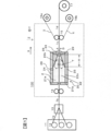
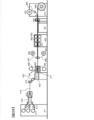
- FIG. 1 is a schematic cross-sectional view showing a prepreg manufacturing method and a coating apparatus according to an embodiment of the present invention.
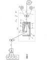
- FIG. 4 is a schematic cross-sectional view showing a prepreg manufacturing method and a coating apparatus according to another embodiment of the present invention.
- FIG. 4 is a schematic cross-sectional view showing a prepreg manufacturing method and a coating apparatus according to another embodiment of the present invention.
- FIG. 4 is a schematic cross-sectional view showing a prepreg manufacturing method and a coating apparatus according to another embodiment of the present invention.
- FIG. 2 is a cross-sectional view illustrating a structure of an application unit outlet when the application unit 20 in FIG. 1 is viewed from a direction opposite to X in FIG. 1.
- FIG. 2 is a cross-sectional view illustrating a structure of an application unit outlet when the application unit 20 in FIG. 1 is viewed from a direction opposite to X in FIG. 1.
- FIG. 2 is a cross-sectional view illustrating a structure inside the application unit when the application unit 20 in FIG. 1 is viewed from a Z direction in FIG. 1.
- FIG. 7 is a cross-sectional view illustrating a flow of a matrix resin 2 in a gap 33 in FIG. 6. It is a figure showing an example of installation of a width regulation mechanism.
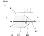
- FIG. 2 is a detailed cross-sectional view of the vicinity of an outlet of a coating unit 20 in the embodiment of FIG.
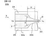
- FIG. 10 is a detailed cross-sectional view of the vicinity of an outlet of a coating unit 20b according to another embodiment different from FIG. 9.
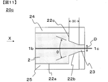
- FIG. 10 is a detailed cross-sectional view of the vicinity of an outlet of a coating unit 20c according to another embodiment different from FIG. 9.
- FIG. 9 is a cross-sectional view illustrating a structure inside the application unit when the application unit 20 in FIG. 1 is viewed from a Z direction in FIG. 1.
- FIG. 7 is a cross-sectional view illustrating
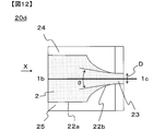
- FIG. 10 is a detailed cross-sectional view of the vicinity of an outlet of a coating unit 20d according to another embodiment different from FIG. 9. It is a detailed cross-sectional view near the exit of the application section 40 of an embodiment different from the present invention.
- FIG. 10 is a detailed cross-sectional view of a coating unit 20e according to another embodiment different from FIG. 9. It is the schematic which shows the example of the prepreg manufacturing process and apparatus using this invention. It is the schematic of an example of another prepreg manufacturing process and apparatus using this invention. It is the schematic of an example of another prepreg manufacturing process and apparatus using this invention. It is a figure showing the example of the mode provided with a plurality of application parts concerning one embodiment of the present invention.
- FIG. 10 is a detailed cross-sectional view of a coating unit 20f according to another embodiment different from FIG. 9. It is the schematic of an example of another prepreg manufacturing process and apparatus using this invention.
- FIG. 10 is a detailed cross-sectional view of a coating unit 20g according to another embodiment different from FIG. 9. It is the schematic of an example of another prepreg manufacturing process and apparatus using this invention. It is the schematic of an example of another prepreg manufacturing process and apparatus using this invention.
- FIG. 10 is a detailed cross-sectional view of an application unit 20h according to another embodiment different from FIG. 9.
- FIG. 1 is a schematic sectional view showing a prepreg manufacturing method and apparatus according to one embodiment of the present invention.
- the coating device 100 is provided between the transport rolls 14 and 15, which are transport mechanisms for moving the reinforcing fiber sheet 1b in a horizontal direction or an inclined direction, and is provided between the transport rolls 14 and 15, and the coating in which the matrix resin 2 is stored.
- a unit 20 is provided.
- the matrix resin may have fluidity by itself, or may have fluidity by containing a solvent, a plasticizer, or the like.
- a winding device 17 for the prepreg 1d is provided.
- the coating device 100 is provided with a matrix resin amount monitoring means and a matrix resin supply device. (The same applies to other examples). Further, a supply device 16a for supplying the release sheet 3 and a supply device 16b for supplying the resin film 4 are provided.
- the reinforcing fiber carbon fiber, glass fiber, metal fiber, metal oxide fiber, metal nitride fiber, organic fiber (aramid fiber, polybenzoxazole fiber, polyvinyl alcohol fiber, polyethylene fiber, polyester fiber, polyamide fiber And the like, but the use of carbon fibers is preferable from the viewpoint of the mechanical properties and light weight of the FRP.
- the reinforcing fiber sheet examples include a unidirectional material (UD base material) in which a plurality of reinforcing fibers are arranged on a surface in one direction, a reinforcing fiber in which reinforcing fibers are arranged in a multiaxial manner, or a sheet formed by random arrangement.
- UD base material unidirectional material
- the reinforcing fiber sheet examples include a unidirectional material (UD base material) in which a plurality of reinforcing fibers are arranged on a surface in one direction, a reinforcing fiber in which reinforcing fibers are arranged in a multiaxial manner, or a sheet formed by random arrangement.
- the method of forming the UD base material is not particularly limited, and may be formed using a known method. It is preferable to form a reinforcing fiber sheet in which single fibers are arranged in advance, and to further arrange the reinforcing fiber bundle to form a reinforcing fiber sheet from the viewpoint of process efficiency and uniform arrangement.
- a tow which is a tape-like reinforcing fiber bundle
- a reinforcing fiber sheet can be obtained by arranging the tape-like reinforcing fiber bundles drawn out from the bobbin.
- the creel is preferably provided with a tension control mechanism when drawing out the reinforcing fibers.
- a tension control mechanism a known mechanism can be used, and a brake mechanism or the like can be used. The tension can also be controlled by adjusting the thread guide.
- the reinforcing fiber fabric include, in addition to woven fabric and knitted fabric, those in which reinforcing fibers are two-dimensionally arranged in a multiaxial manner, and those in which reinforcing fibers such as nonwoven fabric, mat, and paper are randomly oriented.
- the reinforcing fibers can be formed into a sheet using a method such as binder application, entanglement, welding, or fusion.
- a non-crimp woven fabric, a bias structure, an entangled woven fabric, a multiaxial woven fabric, a multiple woven fabric, or the like can be used in addition to the plain woven fabric, twill fabric, and satin woven fabric.
- the woven fabric in which the bias structure and the UD base material are combined not only suppresses the deformation of the woven fabric due to the pulling in the process of applying (also referred to as application) a matrix resin and the impregnation process by the UD structure, but also performs the pseudo structure by the bias structure. It also has isotropy and is a preferred form.
- the multi-layer fabric has an advantage that the structure / characteristics of the fabric upper / lower surface and the inside of the fabric can be individually designed. In the case of a knitted fabric, warp knitting is preferred in consideration of the shape stability in the coating / impregnation step, but a blade which is a tubular knitted fabric can also be used.
- the UD substrate when giving priority to the mechanical properties of FRP, it is preferable to use a UD substrate, and the UD substrate can be produced by a known method in which reinforcing fibers are arranged in a sheet shape in one direction. .
- the method of smoothing is not particularly limited, and examples thereof include a method of physically pressing with a facing roll or the like, and a method of moving a reinforcing fiber using an air flow.
- the physical pressing method is preferred because it is simple and does not easily disturb the arrangement of the reinforcing fibers. More specifically, calendering or the like can be used.
- the method using an air flow is preferable because it not only causes less abrasion but also has the effect of widening the reinforcing fiber sheet.
- the reinforcing fiber sheet it is also preferable to guide the reinforcing fiber sheet to the liquid pool after widening the reinforcing fiber sheet from the viewpoint of efficiently producing a thin prepreg.
- the widening processing method there is no particular limitation on the widening processing method, and examples thereof include a method of mechanically applying vibration and a method of expanding the reinforcing fiber bundle by an air flow.
- a method of mechanically applying vibration there is a method of bringing a reinforcing fiber sheet into contact with a vibrating roll as described in, for example, JP-A-2015-22799.
- the vibration direction when the traveling direction of the reinforcing fiber sheet is the X axis, it is preferable to apply vibrations in the Y axis direction (horizontal direction) and the Z axis direction (vertical direction). It is also preferable to use them in combination. It is preferable that a plurality of projections are provided on the surface of the vibrating roll, because the abrasion of the reinforcing fibers by the roll can be suppressed.
- a method using an air flow see, for example, SEN-I GAKKAISHI, vol. 64, P-262-267 (2008). The described method can be used.
- the reinforcing fiber sheet is heated and then guided to the liquid pool portion, because the temperature decrease of the matrix resin can be suppressed and the viscosity uniformity of the matrix resin can be improved.
- the reinforcing fiber sheet is preferably heated to a temperature close to the matrix resin temperature.
- heating means include air heating, infrared heating, far infrared heating, laser heating, contact heating, and heating medium heating (such as steam). Means can be used. Above all, infrared heating is preferable because the apparatus is simple and the reinforcing fiber sheet can be directly heated, so that it can be efficiently heated to a desired temperature even at a high running speed.
- the matrix resin used in the present invention can be used as a resin composition containing various resins and particles described below, a curing agent, and various additives.
- the prepreg obtained by the present invention is in a state in which the matrix resin is impregnated in the reinforcing fiber sheet, and can be laminated and molded as a sheet-shaped prepreg to obtain a member made of FRP.
- the degree of impregnation can be controlled by additional impregnation after the design of the application section and the application of the matrix resin.
- the matrix resin can be appropriately selected depending on the application, but it is common to use a thermoplastic resin or a thermosetting resin.
- the matrix resin may be a molten resin heated and melted or a matrix resin at room temperature. Further, a solution or a varnish formed using a solvent may be used.
- a resin generally used for FRP such as a thermoplastic resin, a thermosetting resin, and a photocurable resin can be used. Further, these may be used as they are if they are liquids at room temperature, or may be used as solids or viscous liquids at room temperature to reduce the viscosity by heating, or may be used as a melt by melting, or a solvent. May be used as a solution or varnish.
- the thermoplastic resin is selected from a carbon-carbon bond, an amide bond, an imide bond, an ester bond, an ether bond, a carbonate bond, a urethane bond, a urea bond, a thioether bond, a sulfone bond, an imidazole bond, and a carbonyl bond in the main chain.
- a polymer having a bond can be used.
- PPS, PES, PI, PEI, PSU, PEEK, PEKK, PEAK, and the like are suitable.
- polyolefins such as polypropylene (PP), PA, polyester, PPS, and the like are preferable in order to increase molding efficiency.
- PP polypropylene
- PA polypropylene
- polyester polypropylene
- PPS polypropylene
- these may be polymers or oligomers or monomers for low viscosity and low temperature coating. Of course, these may be copolymerized depending on the purpose, or they may be mixed and used as a polymer blend or a polymer alloy.
- thermosetting resin examples include an epoxy resin, a maleimide resin, a polyimide resin, a resin having an acetylene terminal, a resin having a vinyl terminal, a resin having an allyl terminal, a resin having a nadic acid terminal, and a resin having a cyanate ester terminal.
- an epoxy resin a maleimide resin, a polyimide resin, a resin having an acetylene terminal, a resin having a vinyl terminal, a resin having an allyl terminal, a resin having a nadic acid terminal, and a resin having a cyanate ester terminal.
- thermosetting resin suitable for the present invention an epoxy resin is preferably used because of its excellent heat resistance, chemical resistance, and mechanical properties.
- an epoxy resin using an amine, a phenol, or a compound having a carbon-carbon double bond as a precursor is preferable.
- an epoxy resin using amines as a precursor various isomers of tetraglycidyldiaminodiphenylmethane, triglycidyl-p-aminophenol, triglycidyl-m-aminophenol, and triglycidylaminocresol, and phenols are used as precursors.
- the epoxy resin include, but are not limited to, alicyclic epoxy resins. Brominated epoxy resins obtained by brominating these epoxy resins are also used.
- An epoxy resin having an aromatic amine represented by tetraglycidyldiaminodiphenylmethane as a precursor has a good heat resistance and a good adhesion to a reinforcing fiber, and is most suitable for the present invention.
- Thermosetting resin is preferably used in combination with a curing agent.
- the curing agent may be a compound having an active group capable of reacting with an epoxy group.
- a compound having an amino group, an acid anhydride group, or an azide group is suitable.
- dicyandiamide, various isomers of diaminodiphenylsulfone, and aminobenzoic acid esters are suitable. More specifically, dicyandiamide is preferably used because of its excellent prepreg preservability. Further, various isomers of diaminodiphenyl sulfone are most suitable for the present invention because they give cured products having good heat resistance.
- trimethylene glycol di-p-aminobenzoate and neopentyl glycol di-p-aminobenzoate are preferably used.
- the heat resistance is lower than that of diaminodiphenyl sulfone, the tensile strength is lower. Because it is excellent, it is selected and used according to the application. It is also possible to use a curing catalyst if necessary. From the viewpoint of improving the pot life of the matrix resin, it is also possible to use a complexing agent capable of forming a complex with a curing agent or a curing catalyst.
- thermoplastic resin mixed with a thermosetting resin it is also preferable to use a thermoplastic resin mixed with a thermosetting resin.
- a mixture of a thermosetting resin and a thermoplastic resin gives better results than using the thermosetting resin alone. This is because the thermosetting resin is generally capable of low pressure molding by an autoclave while having a brittle defect, whereas the thermoplastic resin is generally difficult to perform low pressure molding by an autoclave while having the advantage of being tough. This is because they exhibit a trade-off characteristic, that is, they can be used in combination to balance physical properties and moldability.
- inorganic particles or organic particles can be contained in the matrix resin or the resin film.
- the type of the inorganic particles can be selected according to the purpose and is not particularly limited.For example, in order to impart conductivity, heat conductivity, thixotropy, and the like, carbon-based particles, boron nitride particles, titanium dioxide particles, silicon dioxide particles, and the like. Can be suitably used.
- the type of the organic particles may be selected according to the purpose, and is not particularly limited. Particularly, the use of polymer particles is preferable because the toughness, impact resistance, and vibration damping properties of the obtained FRP can be improved.
- the glass transition temperature (Tg) or the melting point (Tm) of the polymer particles be higher than the matrix resin temperature by 20 ° C. or more, because the shape of the polymer particles can be easily maintained in the matrix resin.
- the Tg of the polymer particles can be measured using a temperature-modulated DSC under the following conditions.
- the temperature modulation DSC device Q1000 manufactured by TA Instruments or the like is suitable, and it can be used after being calibrated with high-purity indium in a nitrogen atmosphere.
- the measurement conditions are as follows: the temperature rise rate is 2 ° C./min, and the temperature modulation condition is a cycle of 60 seconds and an amplitude of 1 ° C.
- the reversible component is separated from the total heat flow obtained in this way, and the temperature at the middle point of the step signal can be set to Tg.
- Tm is measured by a normal DSC at a heating rate of 10 ° C / min, and the peak top temperature of a peak-like signal corresponding to melting can be defined as Tm.
- the polymer particles do not dissolve in the matrix resin.
- polymer particles for example, appropriate ones can be used with reference to the description in WO2009 / 142231 pamphlet and the like.
- polyamide or polyimide can be preferably used, and polyamide, which can greatly improve impact resistance due to excellent toughness, is most preferable.
- Polyamides such as polyamide 12, polyamide 11, polyamide 6, polyamide 66, polyamide 6/12 copolymer, and the epoxy compound described in Example 1 of JP-A-01-104624 are semi-IPN (polymer interpenetrating network structure). Polyamide (semi-IPN polyamide) or the like can be suitably used.
- the shape of the thermoplastic resin particles may be a spherical particle, a non-spherical particle, or a porous particle, but a spherical shape is particularly preferable in the production method of the present invention since the flow characteristics of the resin are not deteriorated. Further, a spherical shape is a preferable embodiment in that there is no starting point of stress concentration and high impact resistance is given.
- polyamide particles include SP-500, SP-10, TR-1, TR-2, 842P-48, 842P-80 (all manufactured by Toray Industries, Inc.) and "Orgasol (registered trademark)" 1002D. , 2001UD, 2001EXD, 2002D, 3202D, 3501D, 3502D (all manufactured by Arkema Co., Ltd.), "Grillamide (registered trademark)” TR90 (manufactured by Mazaverke Co., Ltd.), "TROGAMID (registered trademark)” CX7323, CX9701 , CX9704 (manufactured by Degussa Co., Ltd.) and the like can be used. These polyamide particles may be used alone or in combination of two or more.
- the number average particle size of the polymer particles is preferably in the range of 5 to 50 ⁇ m, more preferably in the range of 7 to 40 ⁇ m, and still more preferably in the range of 10 to 30 ⁇ m.
- the number average particle diameter is 5 ⁇ m or more, the particles do not enter the bundle of the reinforcing fibers, and can remain in the reinforcing fiber interlayer resin layer of the obtained fiber-reinforced composite material.
- the matrix resin used in the present invention it is preferable to select an optimum viscosity from the viewpoint of processability and stability. Specifically, when the viscosity is in the range of 1 to 60 Pa ⁇ s, the dripping at the constricted portion exit can be suppressed, and the high-speed running property and the stable running property of the reinforcing fiber sheet can be improved, which is preferable.
- the viscosity refers to a value measured at a matrix resin temperature in a liquid reservoir at a strain rate of 3.14 s -1 .
- a viscoelasticity measuring device such as a parallel disk type or a cone type can be used.
- the viscosity of the matrix resin is more preferably 5 to 30 Pa ⁇ s.
- the horizontal direction is shown as the X direction in FIG.
- the reinforcing fiber sheet can be passed in the inclined direction, and traveling in the inclined direction and traveling in the horizontal direction can be combined.
- the tilt direction refers to a direction intermediate between the horizontal direction and the vertical direction. More specifically, the horizontal direction or the inclined direction can be in a range of ⁇ 80 ° to + 80 ° with the horizontal plane being 0 °.
- the running direction of the reinforcing fiber sheet in the constricted part in the application part is in the range of ⁇ 30 ° to + 30 ° with the horizontal plane being 0 °, it becomes possible to incorporate the reinforcing fiber sheet into the existing prepreg manufacturing equipment, and from the viewpoint of versatility of equipment Is preferred.
- the running direction of the reinforcing fiber sheet in the constricted part in the application part is more preferably from ⁇ 15 ° to + 15 ° with the horizontal plane as 0 °.
- the reinforcing fiber sheet is introduced into the application section obliquely downward, and is also described as traveling in the vertical and oblique directions when traveling between the direction changing members in the application section.
- the running direction of the reinforcing fiber sheet is horizontal in a portion where the cross-sectional area is continuously reduced or in a narrow portion.
- the running path of the reinforcing fiber sheet 1b is linearized, and the reinforcing fiber sheet 1b is disturbed due to the thickness of the reinforcing fiber sheet 1b. Is less likely to occur.
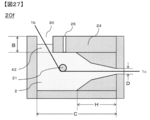
- the application section 20 includes an exit side member 29 facing the main body with a predetermined gap D therebetween, and the wall side members 21a and 21b on the introduction side of the reinforcing fiber sheet 1b, and the exit side member 29 on the exit side. .
- a liquid reservoir 22 and a slit-shaped constriction located on the outlet side of the liquid reservoir 22 and having a cross-sectional area smaller than the maximum cross-sectional area of the liquid reservoir 22.
- a part 23 is formed.
- the reinforcing fiber sheet 1b introduced into the liquid pool section 22 travels in the horizontal direction while accompanying the matrix resin 2 around the reinforcing fiber sheet 1b.
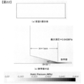
- the accompanying matrix resin 2 is gradually compressed, and the outlet of the liquid reservoir 22 is , The pressure of the matrix resin 2 increases.
- the accompanying liquid flow becomes more difficult to flow in the outlet direction, flows toward the upper member 24 and the lower member 25, and then flows toward the upper member 24 and the lower member 25.
- the increased liquid pressure has an effect that the matrix resin 2 is easily impregnated into the reinforcing fiber sheet 1b.
- This is based on the property (Darcy's law) that when a matrix material is impregnated into a porous body such as a reinforcing fiber bundle, the degree of impregnation increases with the pressure of the matrix resin. Also in this case, when the reinforcing fiber sheet 1b is run at a higher speed, the hydraulic pressure is further increased, so that the impregnation effect can be further enhanced.
- the matrix resin 2 is impregnated with the bubbles remaining inside the reinforcing fiber sheet 1b by gas / liquid displacement, and the bubbles have a continuous cross-sectional area with the portion 22a whose cross-sectional area does not decrease due to the circulating flow T and buoyancy. Are gathered near the boundary of the portion 22b. For this reason, it is preferable to install a degassing mechanism 26 for degassing air bubbles from the matrix resin 2 in the vicinity. More specifically, the installation position of the degassing mechanism is preferably within a range of 5 cm or less from the boundary position between the portion 22a where the cross-sectional area does not decrease and the portion 22b where the cross-sectional area continuously decreases.
- Patent Document 3 impregnation is performed by a plurality of fixed guides, and it is considered that bubbles are generated in a wide range.
- a degassing mechanism is not necessarily installed in the vicinity thereof, and the removal of bubbles is not sufficient. There was a possibility.
- the reinforcing fiber sheet 1b is automatically centered at the center of the gap D by the increased hydraulic pressure, and the reinforcing fiber sheet 1b does not directly rub against the wall of the liquid reservoir 22 or the narrowed portion 23. It also has the effect of suppressing the generation of fluff. This is because, when the reinforcing fiber sheet 1b approaches one of the gaps D due to a disturbance or the like, the matrix resin 2 is pushed into the narrower gap on the approaching side and compressed, so that the hydraulic pressure increases on the approaching side. Then, the reinforcing fiber sheet 1b is pushed back to the center of the gap D.
- the constriction 23 is designed to have a smaller cross-sectional area than the maximum cross-sectional area of the liquid reservoir 22.
- the length of the quasi-plane of the reinforcing fiber sheet 1b in the perpendicular direction is small, that is, the cross-sectional area is small because the interval between the members is small. This is because the impregnation and the self-centering effect can be obtained by increasing the hydraulic pressure in the constricted portion 23 as described above.
- the cross-sectional shape of the entrance portion of the constricted portion 23 be made to match the cross-sectional shape of the surface of the liquid reservoir portion 22 in contact with the narrowed portion 23, from the viewpoint of the running property of the reinforcing fiber sheet 1b and the flow control of the matrix resin 2.
- the constriction 23 may be slightly larger if necessary.
- the reinforcing fiber sheet 1b runs completely in the horizontal direction, but is not limited to this, and the above-described effects of collecting fluff and discharging bubbles can be obtained.
- 1b may travel in the inclined direction in the application section 20 within a range in which the vehicle can run stably continuously. Further, the application section 20 can be inclined.
- the total amount of the matrix resin 2 applied to the reinforcing fiber sheet 1b can be controlled by the gap D of the narrowed portion 23.
- the gap D may be adjusted to be wide.
- FIG. 1 illustrates a case where one reinforcing fiber sheet is introduced into the application section from the horizontal direction.
- the introduction of the reinforcing fiber sheet into the application section is not limited to this, and a plurality of reinforcing fiber sheets may be used as necessary.
- the introduction direction may be the inclined direction. This will be described with reference to FIGS.
- one reinforcing fiber sheet 1b runs obliquely downward from above and is introduced into the application section 20 through the opening 30.
- the running direction of the reinforcing fiber sheet 1 b is changed to a horizontal direction by the direction changing member 31, and the reinforcing fiber sheet 1 b is pulled out from the narrowed portion 23.
- a special sealing mechanism is not required, and the apparatus can be simplified.
- the opening it is also possible to equip the opening with a sealing mechanism as required for various purposes such as filling the liquid pool with an inert gas.
- a sealing mechanism it is preferable that at least the surface of the direction changing member 31 that is in contact with the reinforcing fiber sheet 1b is formed as a curved surface.
- the direction changing member 31 is preferably fixed.
- the direction changing member 31 is preferably a fixed bar having a curved surface, and its cross-sectional shape can be exemplified by a circle, an ellipse, a saddle, and the like.
- a curved surface and a flat surface may be mixed in a portion where the direction changing member 31 and the reinforcing fiber sheet 1b are in contact with each other, but when the ground start portion and the end portion of the reinforcing fiber sheet 1b are curved surfaces, generation of fluff can be suppressed. ,preferable.
- a rotatable roller can be used from the viewpoint of suppressing abrasion between the reinforcing fiber sheet 1b and the direction changing member 31.
- impregnation may be performed by replacing the gas in the reinforcing fiber sheet 1b with the matrix resin 2.
- the impregnation can be promoted more efficiently by pressing the plurality of direction changing members 31 at an angle.
- the installation position of the direction changing member 31 is 1 cm or more from the boundary position between the portion 22a where the cross-sectional area does not decrease and the portion 22b where the cross-sectional area continuously decreases. It is preferable to use the portion 22a that does not decrease.
- two reinforcing fiber sheets 1 b run obliquely downward from above and are introduced into the coating section 20 through the opening 30.
- the running direction of the two reinforcing fiber sheets 1b is changed by the direction changing member 31 to the horizontal direction, and after the two sheets are stacked, the two reinforcing fiber sheets 1b are pulled out from the narrowed portion 23.
- the matrix resin 2 is contained and laminated between the two reinforcing fiber sheets 1b, the impregnation becomes easier to progress in the portion 22b and the constricted portion 23 where the cross-sectional area is continuously reduced, which is preferable.
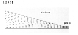
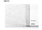
- the length H of the portion 22b where the cross-sectional area is continuously reduced is preferably 10 mm or more, from the viewpoint of suppressing excessive swelling in the thickness direction of the reinforcing fiber sheet 1b laminate, more preferably. Is 30 mm or more. If there is no portion 22b where the cross-sectional area is continuously reduced, the reinforcing fiber sheet 1b laminate containing the matrix resin 2 therein and having an excessive swelling in the thickness direction is rapidly introduced into the constricted portion 23. Therefore, the extra matrix resin 2 cannot be discharged, and if the gap D is thicker than the gap D, the matrix resin 2 is easily clogged.
- the traveling speed of the reinforcing fiber sheet 1b When the length H of the continuously decreasing portion 22b is less than 10 mm and the traveling speed of the reinforcing fiber sheet 1b is sufficiently low, the thickness of the reinforcing fiber sheet 1b laminate can be reduced. When the speed is increased, the effect becomes insufficient, and the clogging is likely to occur. As described above, when H is 30 mm or more, the traveling speed can be increased to 20 m / min or more.
- the length C of the liquid pool portion can be reduced within a range in which the reinforcing fiber sheet can travel, but specifically, the length C is set to 400 mm or less in order to reduce the volume of the liquid pool portion. Is preferred. More preferably, it is 200 mm or less.
- two reinforcing fiber sheets 1b run obliquely downward from above and are introduced into the coating section 20 through the opening 30. Then, the two reinforcing fiber sheets 1 b are impregnated while passing through the plurality of direction changing members 31, and are finally pulled out from the narrowed portion 23 after the two sheets are laminated.
- the shape and the number of the direction changing members 31 for promoting the impregnation can be variously selected according to the purpose.
- the contact length between the direction changing member 31 and the reinforcing fiber sheet 1b and the angle (wrap angle) formed between both ends of the contact portion and the center of the direction changing member 31 can be selected according to the purpose.
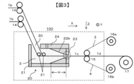
- FIGS. 3 and 4 show an example in which the number of the reinforcing fiber sheets 1b is two, but it is needless to say that any number of the reinforcing fiber sheets 1b can be three or more.
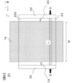
- FIG. 5 is a view of the application unit 20 viewed from the direction opposite to X in FIG.
- the coating portion 20 is provided with a side wall member 32 for preventing the matrix resin 2 from leaking from both ends in the arrangement direction of the reinforcing fiber sheet 1b, and a narrow portion is formed in the space surrounded by the outlet side member 29 and the side wall member 32.
- outlets 28 are formed.
- the outlet 28 has a slit shape, and the sectional aspect ratio (U / D in FIG. 5) may be set according to the shape of the reinforcing fiber sheet 1b to which the matrix resin 2 is to be applied.
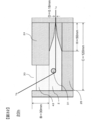
- FIG. 6 is a cross-sectional view illustrating the structure inside the coating unit when the coating unit 20 is viewed from the Z direction.
- the upper surface member 24 is omitted for easy viewing of the drawing.
- FIG. 7 shows the flow of the matrix resin 2 in the gap 33 between the reinforcing fiber sheet 1b and the side wall member 32. If the gap 33 between the reinforcing fiber sheet 1b and the side wall member 32 is large, a vortex flows in the matrix resin 2 in the direction of R.
- the vortex flow R becomes outward flow (Ra) near the boundary between the portion 22b where the cross-sectional area is continuously reduced and the constricted portion 23 in the liquid reservoir 22, so that the reinforcing fiber sheet arranges the reinforcing fiber bundle.
- the flow is in the direction of tearing (breaking of the sheet-like reinforcing fiber bundle).
- the width of the width W of 1b and the following equation (1) is the width of the width W of 1b and the following equation (1).
- an interval L between the left and right side wall members 32 (the width of the end of the liquid pool portion.
- the width L is the width of the terminal of the liquid pool portion).
- the width W of the sheet-shaped reinforcing fiber bundle at the outlet of the constricted portion is set so as to satisfy the relationship of the above equation (1).
- the lower limit of L is not less than W-5 (mm) from the viewpoint of improving the uniformity of the dimension in the width direction of the prepreg 1d.
- this width regulation is, from the viewpoint of suppressing the generation of the vortex R due to high hydraulic pressure at the outlet side of the portion 22b where the cross-sectional area continuously decreases, at least the G at the outlet side of the portion 22b where the cross-sectional area continuously decreases. (FIG. 6). Further, when the width regulation is more preferably performed in the entire area of the portion 22b where the cross-sectional area is continuously reduced, more preferably in the entire area of the liquid reservoir 22, the generation of the vortex R can be almost completely suppressed. As a result, it is possible to almost completely suppress cracks and end breaks in the reinforcing fiber sheet.
- the width regulation may be limited to only the liquid pool portion 22, but if the narrow portion 23 is similarly performed, the primary prepreg 1c It is preferable from the viewpoint of suppressing the excessive matrix resin 2 from being applied to the side surface.
- width regulation mechanisms 34a and 34b may be provided between the side wall members 32, and the width regulation may be performed by such a mechanism.
- the width (W) of the reinforcing fiber sheet 1b at the outlet of the constricted portion 23 and the width (L2) regulated by the width regulating mechanism at the exit side end of the width regulating mechanism is L2 ⁇ W + 10 (mm). It is more preferable that L2 ⁇ W + 2 (mm).
- the lower limit of L2 is preferably adjusted to be not less than W-5 (mm) from the viewpoint of improving the uniformity of the dimension in the width direction of the prepreg 1d.
- L in the above equation (1) is regarded as L2.
- the shape and material of the width regulating mechanism are not particularly limited, but a plate-shaped bush is simple and preferable. Further, by having a width slightly smaller than the distance between the upper surface member 24 and the lower surface member 25 (refer to FIG. 8, the vertical length of the width regulating mechanisms 34 a and 34 b in the figure viewed from the X direction). This is preferable because the horizontal flow of the matrix resin 2 can be prevented. On the other hand, it is possible to suppress the stagnation of the matrix resin 2 in the liquid pool by forming the shape along the internal shape of the liquid pool 22 from the middle portion of the width regulating mechanism to the outlet end, thereby preventing the matrix resin 2 from deteriorating. It is preferable because it can be suppressed.
- FIG. 8 shows an example of a plate-shaped bush as the width regulating mechanism.
- FIG. 8 shows an example in which L2 is constant from the vicinity of the boundary between the portion 22a where the cross-sectional area does not decrease and the portion 22b where the cross-sectional area continuously decreases to the exit.
- the width restricted by the control may be changed.
- the width regulating mechanism can be fixed to the application section 20 by an arbitrary method.
- the liquid pressure is increased in the running direction of the reinforcing fiber sheet by continuously decreasing the cross-sectional area in the running direction of the reinforcing fiber sheet 1b in the liquid reservoir 22.
- the continuous decrease in the cross-sectional area in the running direction of the reinforcing fiber sheet is not particularly limited as long as the hydraulic pressure can be continuously increased in the running direction.
- the liquid reservoir may have a curved shape such as a tapered shape (linear shape) or a trumpet shape.
- the cross-sectional area decreasing portion may be continuous over the entire length of the liquid pool portion, or may include a portion where the cross-sectional area does not decrease or a portion which expands conversely as long as the object and effects of the present invention can be obtained. You may go out. These will be described in detail below with reference to FIGS. 9 to 12. 9 to 12, the vicinity of the outlet is shown, and the vicinity of the introduction portion of the reinforcing fiber sheet 1b, the degassing mechanism, and the like are omitted.
- FIG. 9 is a detailed cross-sectional view of the coating section 20 of FIG.
- the opening angle ⁇ of the taper is preferably small, specifically, an acute angle (90 ° or less).
- ⁇ is more preferably 30 ° or less.
- FIG. 10 is a detailed cross-sectional view of the application section 20b of another embodiment different from FIG. It is the same as the application section 20 in FIG. 9 except that the shape of the portion 22b where the cross-sectional area is continuously reduced is a two-step tapered shape.
- the portion 22b where the cross-sectional area of the liquid reservoir 22 is continuously reduced may be configured by a multi-stage taper portion having two or more stages. At this time, it is preferable to make the opening angle ⁇ of the tapered portion closest to the constricted portion 23 an acute angle from the viewpoint of enhancing the compression effect. Also in this case, it is preferable that the length H of the portion 22b where the cross-sectional area of the liquid reservoir 22 is continuously reduced is 10 mm or more.
- the length H of the portion 22b where the cross-sectional area is continuously reduced is 30 mm or more.
- the portion 22 b where the cross-sectional area of the liquid reservoir 22 is continuously reduced is formed into a multi-stage tapered portion, so that the volume of the matrix resin 2 that can be stored in the liquid reservoir 22 is maintained while the constriction portion 23 is maintained. Can be further reduced. As a result, the liquid pressure generated on the outlet side of the liquid reservoir 22 is further increased, and the effect of eliminating fluff and the effect of impregnating the matrix resin 2 can be further enhanced.
- FIG. 11 is a detailed cross-sectional view of the application unit 20c according to another embodiment different from FIG. It is the same as the application section 20 in FIG. 9 except that the shape of the portion 22b where the cross-sectional area is continuously reduced is stepped. As described above, if there is a portion 22b having a continuously decreasing cross-sectional area at the most outlet side of the liquid reservoir 22, the effect of increasing the liquid pressure, which is the object of the present invention, can be obtained.
- the portion may include a portion 22c whose cross-sectional area decreases intermittently.
- FIG. 12 is a detailed cross-sectional view of the application unit 20d according to another embodiment different from FIG. It is the same as the application section 20 in FIG. 9 except that the shape of the portion 22b where the cross-sectional area is continuously reduced is a trumpet shape (curved shape).
- the portion 22b where the cross-sectional area of the liquid reservoir 22 continuously decreases is tapered (linear), but is not limited to this.
- a trumpet shape (curved shape) as shown in FIG. May be.
- the portion 22b in which the cross-sectional area of the liquid reservoir 22 is continuously reduced has a trumpet shape, the virtual tangent at the most outlet side of the portion 22b in which the cross-sectional area of the liquid reservoir 22 is continuously reduced. It is preferable to make the opening angle ⁇ of the first angle acute.
- the cross-sectional area of the liquid reservoir does not necessarily have to be smoothly reduced unless the object of the present invention is impaired.
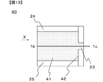
- FIG. 13 is a detailed cross-sectional view of the application section 40 of another embodiment different from the present invention.
- the liquid pool 41 in FIG. 13 does not include a portion where the cross-sectional area continuously decreases in the running direction (X direction) of the reinforcing fiber sheet, and is cut off at the boundary 42 with the narrowed portion 23.
- the area is discontinuous and sharply reduced. Therefore, the reinforcing fiber sheet 1b is easily clogged.
- the matrix resin stored in the liquid reservoir is easily denatured by heat or the like, it is preferable to reduce the volume of the liquid reservoir as much as possible from the viewpoint of the quality stability of the obtained prepreg and the process stability of coating. preferable.
- the volume of the liquid reservoir is excessively reduced, it may be assumed that the supply of the matrix resin to the liquid reservoir is likely to be insufficient with respect to the applied amount. In such a case, there is a possibility that the circulating flow in the liquid pool portion becomes uneven, and the running property of the reinforcing fiber sheet becomes poor.
- the storage portion 43 for this purpose can be formed by, for example, the wall member 21 and the upper surface member 24, but is not limited thereto.
- the distance B defined by the lower surface of the upper surface member 24 and the upper surface of the storage portion 43 in FIG. 14 is preferably 100 mm or less, and the traveling path of the reinforcing fiber sheet 1b. In consideration of the degree of freedom of design, it is preferably 50 mm or less.
- FIG. 1 shows a case where a resin film 4 is provided on one surface and a release sheet 3 is provided on the other surface.
- the resin film 4 is supplied from the supply device 16b
- the release sheet 3 is supplied from the supply device 16a
- the release film 3 can be stacked on the transport roll 15 on the primary prepreg 1c.
- FIG. 1 shows an example in which one resin film 4 and one release sheet 3 are laminated, depending on the purpose, only the resin film 4 or only the release sheet 3 is laminated.
- the resin film may be laminated on both sides, or the release sheet may be laminated on both sides. Further, a mode in which the resin film and the release sheet are laminated may be employed.
- the type of resin constituting the resin film can be appropriately selected according to the purpose, and may be a mixture of a plurality of types of resins. When two resin films are used, they may be the same resin film or different types of resin films. When two release sheets are used, they may be of the same type or different types.
- the release sheet a sheet formed of a polymer having a release action or a sheet in which a release layer is provided on a substrate, for example, a sheet in which a release layer is laminated on the resin film described above is used. It can also be supplied.
- the above description is not limited to the embodiment of FIG. 1, and the same can be applied to the embodiments of other drawings.
- the resin used for the resin film is not particularly limited, and can be appropriately selected depending on the purpose.
- the resin used as the resin film may be a single resin, a blend of different polymers, or a resin composition that is a blend of various components.
- the resin film used here can contain the particles.
- a matrix resin containing particles is used in the application step, the viscosity tends to increase, and the uniformity of application may be deteriorated during high-speed running of the reinforcing fiber sheet. For this reason, it is preferable to apply the particles in the resin film applying step because the high-speed running stability of the reinforcing fiber sheet in the applying step is improved.
- the resin film containing particles may be a resin film made of a matrix resin.
- the matrix resin can be applied while the particles are applied separately from the coating step, so that it is efficient.
- the matrix resin of the matrix resin containing particles may be the same as or different from the matrix resin component used in the coating step.
- the components of the matrix resin used in the coating step and the matrix resin to be formed into a resin film can be adjusted in consideration of the high-speed running stability in the coating step and the pot life in storage in the coating section.
- a certain resin component can be taken out of the matrix resin and formed into a resin film.
- a thermoplastic resin can be blended with a matrix resin mainly composed of a thermosetting resin to improve the toughness of the resin.
- this thermoplastic resin may increase the viscosity of the matrix resin.
- application stability can be improved by applying the thermoplastic resin as a resin film to the primary prepreg without using it as a component of the matrix resin applied in the application step.
- PES, PEI, PI, and the like are often used as such a thermoplastic resin.
- such a thermoplastic resin film may be a self-supporting film that does not require a support in some cases, and is useful from the viewpoint that the support can be omitted.
- the method for obtaining the resin film is not particularly limited, and a known method can be used.For example, using a known coater such as a roll coater, a comma coater, a knife coater, a die coater, and a spray coater, film formation is performed. You can do it. Further, if necessary, a resin can be applied on a support such as a release sheet to form a film.
- a known coater such as a roll coater, a comma coater, a knife coater, a die coater, and a spray coater.
- a traveling mechanism for transporting the reinforcing fiber sheet or the prepreg of the present invention As a traveling mechanism for transporting the reinforcing fiber sheet or the prepreg of the present invention, a known roller or the like can be suitably used. In the present invention, since the reinforcing fiber sheet is conveyed in the horizontal direction or the inclined direction, it is preferable to arrange rollers before and after the application section.
- the running path of the reinforcing fiber sheet is as straight as possible in order to suppress the arrangement disorder and the fluffing of the reinforcing fiber.
- the prepreg is often a sheet-like integrated body that is a laminate with a release sheet, but in the conveying step of the prepreg, if there is a bent portion, wrinkles may occur due to a difference in circumference between the inner layer and the outer layer. Therefore, it is preferable that the traveling path of the sheet-shaped integrated object is as straight as possible. From this viewpoint, it is preferable to use a nip roll in the traveling path of the sheet-like integrated object.
- Whether the S-shaped roll or the nip roll is used can be appropriately selected according to the manufacturing conditions and the characteristics of the product.
- a high tension take-up device for drawing out the prepreg from the application section downstream of the application section. This is because high frictional force and shear stress are generated between the reinforcing fiber sheet and the matrix resin in the application section, and it is preferable to generate a high take-up tension downstream of the process in order to overcome the drawback and draw out the prepreg. It is.
- a high tension take-up device a nip roll, an S-shaped roll, a belt press, or the like can be used. In any case, by increasing the frictional force between the device and the prepreg, slip can be prevented and stable running can be achieved.
- the belt press is reliable.
- the S-shaped roll is preferable because the frictional force can be easily controlled by the roll diameter and the contact length.
- a release sheet feeding device or a winder can be used as appropriate, and as such a device, a known device can be used. It is preferable to provide a mechanism capable of feeding back the winding tension or feeding back the winding speed from the viewpoint of stable running of the sheet.
- Additional impregnation In order to adjust the degree of impregnation to a desired degree, it is also possible to combine a means for further increasing the degree of impregnation using an impregnating apparatus separately after coating with the present invention.
- additional impregnation after application is referred to as additional impregnation
- an apparatus therefor is referred to as an additional impregnation apparatus.
- the device used as the additional impregnation device is not particularly limited, and can be appropriately selected from known devices according to the purpose.
- a laminate of a sheet-like carbon fiber bundle and a resin is preheated by a hot plate to sufficiently soften the resin on the sheet-like carbon fiber bundle.
- the impregnation can also be advanced by using a device that presses with a heated nip roll.
- the temperature of the hot plate for preheating, the surface temperature of the nip roll, the linear pressure of the nip roll, and the diameter and number of the nip rolls can be appropriately selected so as to obtain a desired impregnation degree.
- FIG. 1 shows an example in which the prepreg sheet runs in an S-shape, but if impregnation is possible, the contact length between the sheet and the roll, such as a U-shape, V-shape or ⁇ -shape, is described. May be adjusted.
- the impregnation pressure is increased to increase the degree of impregnation, it is also possible to add an opposing contact roll. Further, as shown in FIG.
- a heated nip roll or a heated S-shaped roll can be used, but the roll diameter, the set pressure, and the contact length between the primary prepreg and the roll can be reduced as compared with a normal impregnating device. This is preferable because not only the size can be reduced but also the power consumption and the like can be reduced.
- a release sheet to the primary prepreg before the primary prepreg enters the simple additional impregnating apparatus, because the running property of the primary prepreg is improved.
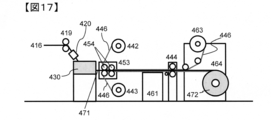
- FIG. 17 shows an example of a prepreg manufacturing process equipped with a simple additional impregnation device.
- a simple additional impregnation device 453 is provided immediately after the application section 430.
- the simple additional impregnation device 453 shows an example of a nip roll, but the nip roller preferably has a heating mechanism.
- the number of nip rolls can be appropriately selected depending on the purpose, but from the viewpoint of simplification of the process, three or less nip rolls are preferable (FIG. 17 shows an example of two nip rolls).
- the nip roller is provided with a driving device from the viewpoint that tension control of prepreg conveyance is easy.
- the nip pressure can be appropriately adjusted according to the desired degree of impregnation.
- the nip roll surface is subjected to an appropriate release treatment so that the primary prepreg does not stick, or a release sheet is inserted between the primary prepreg and the nip roll.
- the release sheet can be inserted from the application section 430 side and the release sheet can be separated from the primary prepreg by the roll on the high tension take-off device 444 side.
- the separated release sheet may be wound up as it is, or may be run again on the circuit so as to be inserted again from the application section 430 side.
- the prepreg referred to in the present invention is a reinforced fiber sheet provided with a matrix resin, and is a two-dimensional sheet-like intermediate substrate for producing FRP.
- a so-called drawn material is also included in the prepreg without departing from this meaning.
- the width of the prepreg is not particularly limited, and the prepreg may be manufactured in a narrow tape shape or a wide width up to about 2 m.
- the thickness of the prepreg is not particularly limited, but is generally about 0.05 mm to 1 mm.
- the impregnation ratio of the matrix resin is desirably 10% or more.
- the state of the impregnation of the matrix resin can be confirmed by tearing the collected prepreg and visually observing the inside, and can be more quantitatively evaluated by, for example, a peeling method.
- the impregnation rate of the matrix resin by the peeling method can be measured as follows. That is, the collected prepreg is sandwiched between adhesive tapes, and the prepreg is peeled off to separate the reinforcing fibers to which the matrix resin has adhered from the reinforcing fibers to which the matrix resin has not adhered.
- the ratio of the mass of the reinforcing fibers to which the matrix resin has adhered to the mass of the entire reinforcing fiber sheet put in can be taken as the impregnation rate of the matrix resin by the peeling method.
- the degree of impregnation can also be evaluated based on the water absorption due to the capillary action of the prepreg. Specifically, in accordance with the method described in JP-T-2016-510077, the prepreg can be cut into 10 cm ⁇ 10 cm, one side of which is 5 mm, and can be calculated from the change in mass when immersed in water for 5 minutes. .
- the width of the prepreg is not particularly limited, and may be a wide width of about several tens cm to 2 m, or a tape having a width of several mm to several tens mm.
- the width can be selected according to the application.
- devices called ATL (Automated Tape Laying) or AFP (Automated Fiber Placement) for automatically laminating narrow-width prepregs and prepreg tapes have been widely used in order to streamline the prepreg lamination process. Therefore, it is also preferable that the width is adjusted to this.
- ATL often uses narrow prepregs having a width of about 7.5 cm, about 15 cm, or about 30 cm.
- AFP often uses prepreg tapes having a width of about 3 mm to about 25 mm.
- the width of the coating portion used in the present invention can be adjusted so as to have a desired width from the beginning. For example, when manufacturing a narrow prepreg having a width of 30 cm for ATL, the width of the application section outlet may be adjusted accordingly. In addition, in order to manufacture this efficiently, it is preferable to manufacture the product with a product width of 30 cm. When a plurality of such manufacturing devices are arranged in parallel, the same traveling device / transport device, various rolls, and a winder are used. The prepreg of the line can be manufactured.
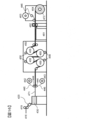
- FIG. 18 shows an example in which five application units are connected in parallel in one example.
- the five reinforced fiber sheets 416 may pass through five independent application parts 430 to obtain five primary prepregs 471, or the application parts 430 may be integrated in a parallel direction. It may be.
- the coating unit 430 may be provided with five independent width control mechanisms and five coating unit outlet widths.
- a reinforcing fiber sheet in the form of a tape-shaped reinforcing fiber bundle having about 1 to 4 yarns is formed and passed through a coating section whose width has been adjusted so as to obtain a desired tape width. You can also get it.
- the accuracy of the tape width is often required from the viewpoint of controlling the lateral overlap between the tapes. For this reason, it is preferable to more strictly control the outlet width of the application section.
- the above L, L2, and W satisfy the relationship of L ⁇ W + 1 mm and / or L2 ⁇ W + 1 mm. .
- the method of slitting the prepreg is not particularly limited, and a known slit device can be used. After winding the prepreg once, it may be installed in the slit device again to perform slitting, or for efficiency, a slit step may be arranged continuously from the prepreg production step without winding the prepreg once. Also, in the slitting step, a wide prepreg of 1 m or more may be directly slit to a desired width, or once cut and divided into narrow prepregs of about 30 cm, and then slit again to a desired width. good.
- a release sheet may be supplied independently, or one wide release sheet may be supplied.
- a plurality of prepregs may be stacked. The end in the width direction of the prepreg thus obtained can be cut off and supplied to an ATL or AFP device.
- the matrix resin component resin in the case of FRP
- adhering to the slit cutter blade can be reduced, and the cleaning cycle of the slit cutter blade is extended. There is also an advantage that you can do it.
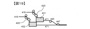
- FIG. 19 shows an example of an embodiment in which prepregs are stacked using two application sections.
- the two primary prepregs 471 pulled out from the first coating unit 431 and the second coating unit 432 pass through the direction change roll 445 and are stacked by the stacking roll 447 downstream thereof. At this time, it is preferable to position the release sheet between the primary prepreg 471 and the direction change roll, because it is possible to suppress the prepreg from sticking to the roll and to stabilize traveling.
- the direction change roll can be replaced with a direction change guide or the like subjected to a release treatment.By using such a laminated prepreg, the efficiency of the prepreg laminating step can be improved, This is effective, for example, when manufacturing a thick FRP. Further, it is expected that the toughness and impact resistance of the FRP will be improved by laminating thin prepregs in multiple layers, and by applying the present production method, thin multilayer prepregs can be efficiently obtained. Further, by easily laminating different types of prepregs, a hetero-bonded prepreg having added functionality can be easily obtained. In this case, it is possible to change the type and fineness of the reinforcing fiber, the number of filaments, mechanical properties, fiber surface characteristics, and the like.
- a different matrix resin resin in the case of prepreg.
- a prepreg having a different thickness or a heterojunction prepreg obtained by laminating prepregs having different mechanical properties can be used.
- a resin having excellent mechanical properties is provided in the first application section, and a resin having excellent tack properties is provided in the second application section.
- a resin without particles can be applied in the first application section, and a resin containing particles can be applied in the second application section.
- a plurality of application sections are arranged in parallel to the running direction of the reinforcing fiber sheet, that is, a plurality of application sections are arranged in parallel in the width direction of the reinforcing fiber sheet.
- a plurality of application portions can be arranged in series in the running direction of the reinforcing fiber sheet.
- the type of matrix resin can be changed in the thickness direction of the primary prepreg.
- running stability and high-speed running performance can be improved by changing the application conditions depending on the application section.
- a resin having excellent mechanical properties is applied in the first application section
- a resin having excellent tack properties is applied in the second application section
- a prepreg that can achieve both mechanical properties and tackiness by laminating them is easily provided.
- a resin without particles can be applied in the first application section, and a resin containing particles can be applied in the second application section.
- the manufacturing method of the present invention is not only capable of improving the efficiency and stabilization of the manufacturing, but also is capable of improving the performance and functioning of the product, and is a manufacturing method excellent in expandability.
- the matrix resin is stored in the coating section, but it is preferable to appropriately supply the matrix resin because the coating proceeds.
- the mechanism for supplying the matrix resin to the application section is not particularly limited, and a known device can be used. It is preferable that the matrix resin be continuously supplied to the application section because the running of the reinforcing fiber sheet can be stabilized without disturbing the liquid level above the application section.
- the self-weight can be supplied as a driving force from a tank storing the matrix resin, or can be supplied continuously using a pump or the like.
- a pump, a gear pump, a tube pump, a pressure pump, or the like can be used as appropriate according to the properties of the matrix resin.
- the matrix resin When the matrix resin is solid at room temperature, it is preferable to provide a melter above the reservoir. Further, a continuous extruder or the like can be used. Further, it is preferable to provide a mechanism capable of continuously supplying the matrix resin in accordance with the applied amount so that the liquid level above the application portion of the matrix resin is as constant as possible. For this purpose, for example, as described above, a mechanism that monitors the liquid level, the weight of the application section, and the like and feeds it back to the supply device can be considered.
- the online monitoring method is not particularly limited, and a known method can be used.
- a device for measuring the thickness for example, a beta-ray meter or the like can be used.
- the application amount monitored online is immediately fed back to the application section, and can be used for adjusting the temperature of the application section and the gap D (see FIG. 1) of the constricted section 23.
- Application amount monitoring can of course be used as defect monitoring.
- As the thickness measurement position for example, in FIG.
- the thickness of the reinforcing fiber sheet 416 is measured before being introduced into the application section 430, and the thickness of the prepreg is measured between the application section 430 and the high tension take-up device 444. can do. It is also preferable to perform online defect monitoring using infrared rays, near infrared rays, a camera (image analysis), or the like.
- the coating apparatus of the present invention has a traveling mechanism for causing a reinforcing fiber sheet in which reinforcing fibers are arranged in one direction to travel vertically downward, and an application mechanism, and the application mechanism can store a matrix resin therein. And further comprising a liquid reservoir and a constricted portion which are communicated with each other, wherein the liquid reservoir has a portion whose cross-sectional area continuously decreases along the running direction of the reinforcing fiber sheet, and wherein the constricted portion is , Having a slit-shaped cross section and having a smaller cross-sectional area than the upper surface of the liquid reservoir.
- FIG. 15 is a schematic view of an example of a prepreg manufacturing process / apparatus using the present invention.
- the plurality of reinforcing fiber bobbins 412 are hung on a creel 411, and are pulled out via a direction changing guide 413.
- the reinforcing fibers 414 can be pulled out at a constant tension by a brake mechanism provided to the creel.
- the plurality of pulled out reinforcing fibers 414 are orderly arranged by the reinforcing fiber arrangement device 415, and the reinforcing fiber sheet 416 is formed.
- FIG. 15 is a schematic view of an example of a prepreg manufacturing process / apparatus using the present invention.
- the plurality of reinforcing fiber bobbins 412 are hung on a creel 411, and are pulled out via a direction changing guide 413.
- the reinforcing fibers 414 can be pulled out at a constant tension by a brake mechanism provided to the creel.
- the reinforcing fiber sheet preheating device 420 and the coating unit 430 can be used to match the temperature of the matrix resin in the application section with the temperature of the reinforcing fiber sheet as much as possible, but can be omitted.
- the reinforcing fiber sheet 416 is conveyed linearly from the reinforcing fiber arrangement device 415 to the conveying roll 419 between the devices.
- the widening device 417 and the smoothing device 418 can be appropriately skipped or the devices can be omitted depending on the purpose.
- the arrangement order of the reinforcing fiber arrangement device 415, the widening device 417, and the smoothing device 418 can be appropriately changed according to the purpose.
- the reinforcing fiber sheet 416 travels obliquely downward from the transport roll 419, and reaches the high tension take-up device 444 via the application unit 430.
- the application section 430 can adopt any application section shape as long as the object of the present invention is achieved. For example, the shapes as shown in FIGS. 9 to 12, FIG. 14, FIG. 27, FIG. 29, and FIG. Further, if necessary, a width regulating mechanism can be provided as shown in FIG. In FIG.
- the release sheet or the resin film 446 unwound from the supply devices 442 and 443 can be laminated on the primary prepreg 471 on the high tension take-up device 444.
- the resin film and the release sheet may be used alone or as a laminate of the resin film and the release sheet. At this time, it is preferable to make the resin surface adhere to the prepreg surface.
- a release paper, a release film, or the like can be used as the release sheet.
- a nip roll is drawn as the high tension take-up device 444.
- the sheet-like integrated material passes through an additional impregnating device 450 provided with a hot plate 451 and a heating nip roll 452, is cooled by a cooling device 461, is taken off by a take-off device 462, and peels off the upper release sheet 446. Then, a sheet-like integrated body 472 composed of a prepreg / release sheet as a product can be obtained by winding with a winder 464. Since the sheet-like integrated object is conveyed in a basic straight line from the high tension take-up device 444 to the winder 464, the occurrence of wrinkles can be suppressed.
- FIG. 15 illustrations of the matrix resin supply device and the online monitoring device are omitted.
- FIG. 16 is a schematic view of another example of a prepreg manufacturing process / apparatus using the present invention.
- FIG. 16 depicts an example in which two S-2 rolls 455 of the "S-wrap roll" type are used as the additional impregnation device (two rolls in total), but the number of rolls depends on the purpose. Can be increased or decreased.
- a contact roll 456 for enhancing the impregnation effect is also drawn, but it is of course possible to omit it depending on the purpose.
- FIG. 17 is a schematic view of another example of a prepreg manufacturing process / apparatus using the present invention.
- an example using a simple additional impregnation device is shown.
- the simple additional impregnation device 453 is installed immediately after the coating section 430, the prepreg 471 is guided to the simple additional impregnation device 453 in a high temperature state, so that the impregnation device can be simplified and downsized.
- the heating nip roll 454 is drawn as an example, but a small heating S-shaped roll may be used depending on the purpose.
- the use of the simple additional impregnation apparatus is also advantageous in that the entire prepreg manufacturing apparatus can be made very compact.
- the resin film 446 is a particle-containing resin film, it is preferable to increase the degree of impregnation of the primary prepreg, because the particles in the resin film can be arranged on the prepreg surface layer in the next step.
- STAR-CCM + manufactured by SIMENS was used as software, and the Navier-Stokes equation was solved to numerically analyze the liquid flow and the liquid pressure at the portion where the cross-sectional area decreases intermittently. More specifically, a portion where the cross-sectional area decreases intermittently is modeled as a fluid portion, and a two-dimensional flow, that is, a fluid (matrix resin) flows only in the XZ plane and does not flow in the Y direction. It was assumed that. At this time, the viscosity of the fluid was 10 Pa ⁇ s, the density was 1000 kg / m 3 , and the running speed of the reinforcing fiber sheet was 20 m / min.
- FIG. 23 shows a state in which a flow in the direction opposite to the running direction of the reinforcing fiber sheet is formed near the constriction.
- the flow in the direction along the outlet side member near the constricted part becomes large, and the formation of the flow in the direction opposite to the running direction of the reinforcing fiber sheet is reduced. It is suggested that it is weak (FIG. 25).
- FIG. 26 shows a comparison of FIG. 26 in which the flow velocity when H is changed is colored in gray scale.
- the flow chart shows that the darker the color, the higher the flow velocity.
- Example 1 Thermosetting wide prepreg (1)>
- an application unit of the application unit 20f type shown in FIG. 27 is used, and as a prepreg manufacturing apparatus, a widening device, a smoothing device, and additional impregnation are used from the device having the configuration shown in FIG. A device other than the device can be used.
- the side wall member of the application section can be made of an acrylic resin plate so that the inside can be observed.
- the direction of travel of the reinforcing fiber sheet in the liquid reservoir is horizontal, and the liquid reservoir has a two-stage taper shape.
- the first-stage taper has an opening angle of 15 to 20 ° and a taper length (ie, H) of 10 degrees.
- the opening angle of the second-stage taper can be 5 to 10 °.
- a plate-shaped bush adapted to the inner shape of the application portion as shown in FIG. 8 is provided, and the installation position of the plate-shaped bush can be freely changed so that L2 can be appropriately adjusted.
- the width U of the stenosis portion can be 300 mm when L2 is 300 mm.
- the gap D of the stenotic portion is about 0.18 mm, and can be adjusted according to a desired basis weight.
- the aspect ratio of the exit slit is 1500.
- the stenotic portion outlet surface can be used with the outside of the bush closed.
- the distance B defined by the upper surface of the liquid reservoir and the upper surface of the reservoir can be 50 to 70 mm.
- the length C of the liquid pool portion can be shortened as long as the reinforcing fiber sheet can travel, and specifically, can be set to 100 to 200 mm.
- a carbon fiber manufactured by Toray, “Treca (registered trademark)” T800S (24K)
- a thermosetting epoxy resin composition described later can be used as a matrix resin.
- the number of reinforcing fiber bobbins can be changed according to the basis weight of the prepreg to be produced, a prepreg having a general basis weight can be obtained with 56 yarns.
- a biphenol type epoxy resin (“jER (registered trademark) 825” manufactured by Mitsubishi Chemical Corporation) was used as a matrix resin, and the running speed of the reinforcing fiber sheet and the prepreg was reduced to 5 at room temperature (resin viscosity was equivalent to 4 to 7 Pa ⁇ s).
- a prepreg can be produced at a speed of 2525 m / min.
- the application section is made of a transparent material such as acryl as in this example, the inside of the application section can be observed, so that the running property of the reinforcing fiber sheet can be evaluated. More specifically, the evaluation of the continuous running performance can be performed as follows. That is, the reinforcing fiber sheet is allowed to run continuously for 30 minutes, and a case where there is no fuzz clogging / yarn breakage is “Good”, and a case where the fluff is clogged and yarn breakage is “Bad”. In addition, in order to evaluate the signs of fuzz clogging, the application portion is disassembled after continuous running for 60 minutes and 120 minutes, and the liquid contact surface of the upper surface member is visually observed to check for fuzz.
- a fuzz attached to the vicinity of the constriction after continuous running is referred to as “poor”, and a portion far from the constriction after continuous running (a boundary between a portion where the cross-sectional area does not decrease and a portion where the cross-sectional area continuously decreases).
- (Around) is referred to as a fuzz-preventing property “Fair”, and a piece having no fuzz adhering to the liquid contact surface of the upper surface member after continuous running is referred to as “Good”.
- the vehicle is continuously driven at a running speed of 20 m / min for 60 minutes, and the reinforcing fiber sheet is cracked at the boundary between the portion where the cross-sectional area does not decrease and the portion where the cross-sectional area continuously decreases (the sheet is reinforced in a vertical streak shape).
- the time during which the fiber runs uniformly without the fiber bundle being torn) or the end of the reinforcing fiber bundle being broken (the part where the reinforcing fiber bundle overlaps) is measured.
- “Excellent” means that the ratio of the time during which the fiber bundle is running uniformly without cracks and end breaks of the fiber bundle is 90% or more of the total running time, and “Good” means that the ratio is 50% or more and less than 90%. "10% or more and less than 50% is" Fair “, and less than 10% is” Poor ".
- the impregnation rate by the peeling method can be made 50% or more.
- the impregnation rate by the peeling method is as follows: The collected prepreg is sandwiched between adhesive tapes, peeled off, and the reinforcing fiber with matrix resin and the reinforcing fiber without matrix resin are separated. The ratio is calculated from the ratio of the mass of the reinforcing fiber to which the matrix resin adheres to the mass of the reinforcing fiber.
- the basis weight of the primary prepreg thus obtained in the width direction of 100 mm square can be kept within the range of plus or minus 2% by mass for both carbon fiber and resin, and it is possible to obtain excellent uniformity of the basis weight in the width direction.
- Example 2 Thermosetting wide prepreg (2)>
- the coating section is made of stainless steel, and a plate heater is attached to the outer circumference of the coating section to further heat the matrix resin, so that the temperature and viscosity of the matrix resin can be adjusted while measuring the temperature with a thermocouple.
- the same application section, prepreg manufacturing apparatus, and reinforcing fiber sheet as those in Example 1 described above can be used.
- matrix resin A which is a thermosetting epoxy resin composition
- This is a mixture of an epoxy resin (a mixture of an aromatic amine type epoxy resin and a bisphenol type epoxy resin), a curing agent (diaminodiphenyl sulfone), and a polyether sulfone, and does not contain polymer particles.
- the viscosity of the matrix resin A can be measured using ARES-G2 manufactured by TA Instruments, a measurement frequency of 0.5 Hz, a heating rate of 1.5 ° C./min, 50 Pa ⁇ s at 75 ° C., 15 Pa ⁇ s at 90 ° C., It is 4 Pa ⁇ s at 105 ° C.
- a prepreg can be prepared by setting the matrix resin temperature of the application section to 75 to 105 ° C. and the running speed of the reinforcing fiber sheet and prepreg to 5 to 25 m / min.
- the first-stage taper of the application section has an opening angle of 17 °
- the second-stage taper has an opening angle of 7 °
- H 70 mm
- L2-W 0 mm
- the matrix resin temperature of the application section is 90 ° C.
- the reinforcing fibers When a prepreg is prepared by setting the running speed of the sheet and the prepreg at 20 m / min and the high-speed running property is evaluated, there is no fluff and yarn clogging and the fuzz preventing property can be good. Further, the impregnation degree by the peeling method can be within 50% or more, and the uniformity of the basis weight in the width direction can be within ⁇ 2%.
- Example 3 Thermosetting wide prepreg (3)>
- the application section is the same as in Example 2, and the prepreg manufacturing apparatus shown in FIG. 28 can be used.
- the reinforcing fiber sheet described in Example 2 is coated with the matrix resin A also described in Example 2 at 80 to 100 ° C. to obtain a primary prepreg. Then, additional impregnation is performed by an additional impregnation device installed immediately after the coating section, and the degree of impregnation can be increased so that the impregnation rate based on the water absorption rate becomes 3 to 15%.
- the simple additional impregnation device can be a multi-stage nip roll, and a release sheet can be inserted on the nip roll. The release sheet can be run on a circuit.
- the impregnation ratio based on the water absorption is calculated from the mass change when a prepreg is cut into 10 cm ⁇ 10 cm, one side of which is 5 mm, and immersed in water for 5 minutes according to the method described in JP-T-2016-510077. it can. Thereafter, the resin film is laminated on the prepreg having a high degree of impregnation from above and below or from one side, and this is guided to an additional impregnator to adjust the impregnation rate to 0.1 to 15%.
- the running speed of the reinforcing fiber sheet or prepreg can be 5 to 25 m / min.
- the first-stage taper of the application section has an opening angle of 17 °
- the second-stage taper has an opening angle of 7 °
- H 70 mm
- L2-W 0 mm
- the temperature of the matrix resin A of the application section is 90 ° C.
- a prepreg is prepared by setting the surface temperature of the nip roll of the simple additional impregnating device to 100 ° C., using a laminated body of a matrix resin B film described later and a release sheet as a resin film, and setting the traveling speed of the reinforcing fiber sheet and the prepreg to 20 m / min. Then, the impregnation rate based on the water absorption rate can be set to about 5%.
- the matrix resin B is a thermosetting epoxy resin composition, and a mixture of an epoxy resin (a mixture of an aromatic amine type epoxy resin and a bisphenol type epoxy resin), a curing agent (diaminodiphenyl sulfone), a polyether sulfone, and a polymer.
- an epoxy resin a mixture of an aromatic amine type epoxy resin and a bisphenol type epoxy resin
- a curing agent diaminodiphenyl sulfone
- a polyether sulfone a polymer.
- the viscosity thereof was 118 Pa ⁇ s at 75 ° C., 32 Pa ⁇ s at 90 ° C., and 10 Pa ⁇ s at 105 ° C. when measured at a measurement frequency of 0.5 Hz and a heating rate of 1.5 ° C./min.
- This matrix resin B can be used as a resin film by a known method.
- CFRP tensile strength
- the tensile strength can be about 3.0 GPa, which is a mechanical property suitable as a structural material for aerospace.
- the CFRP tensile strength is measured in the same manner as in WO2011 / 118106 pamphlet, and a value obtained by standardizing the volume% of the reinforcing fibers in the prepreg to 56.5% can be used.
- the cross section of the obtained CFRP is such that the reinforcing fiber layers are orderly laminated in the horizontal direction, a matrix resin layer is formed between the reinforcing fiber layers, and polymer particles are further provided between the reinforcing fiber layers. Most of can be arranged. This state can be confirmed by CFRP cross-sectional observation using an electron microscope or the like.
- the tensile strength of CFRP obtained by curing a prepreg prepared by a conventional hot melt method using carbon fiber and matrix resin A at 180 ° C. and 6 kgf / cm 2 (0.588 MPa) for 2 hours using an autoclave is 2. It is about 9 GPa.
- Example 4 Thermoplastic prepreg tape (1)>
- the initial impregnation is performed by passing a plurality of reinforcing fiber sheets through a plurality of direction changing members provided in the liquid pool section, and after laminating / unifying, further narrowing is performed.
- the prepreg cross-sectional shape can be shaped.
- a matrix resin mainly composed of a thermoplastic resin, particularly a super engineering plastic having high heat resistance is used, a particularly high-temperature process is required for the impregnation.
- the application section as shown in FIG. 29 can be cited as a preferable example.
- an inert gas such as nitrogen or argon.
- L2-W 0-1 mm
- B 30-70 mm
- C 250-350 mm
- the application section is filled with nitrogen, and a degassing mechanism can be used.
- the apparatus shown in FIG. 23 can be used.
- one reinforcing fiber sheet is formed by arranging three reinforcing fibers, and two sheets are used to produce a prepreg. However, the number of reinforcing fiber bobbins and the number of reinforcing fiber sheets are shown.
- a reinforcing fiber a carbon fiber (manufactured by Toray, "Treca (registered trademark)" T800S (24K)) is used, and a single reinforcing fiber sheet is formed with three yarns, and two sheets of the reinforcing fiber sheet are used.
- a prepreg having a width of 20 mm is manufactured.
- a prepreg is manufactured by using low-viscosity polyamide 6 as the matrix resin and setting the temperature of the matrix resin in the application section to 280 to 300 ° C. At this time, as shown in FIG. A nip roll is provided, and the surface temperature of the nip roll is set to 200 to 250 ° C.
- the running speed of the reinforcing fiber sheet or prepreg can be 5 to 20 m / min.
- the molded article of the thermoplastic prepreg obtained in this way has no voids inside and can exhibit good mechanical properties.
- a calender roll and a traction apparatus can be arranged downstream of the simple additional impregnation apparatus, for example, as described in Patent Document 3.
- Example 5 Thermoplastic prepreg tape (2)>
- the matrix resin can be changed to super engineering plastic.
- the temperature of the matrix resin in the application section is 350 to 420 ° C.
- the surface of the nip roll for easy additional impregnation is used.
- Complete impregnation can be performed at a temperature of 300 to 400 ° C.
- PEKK complete impregnation can be performed by setting the temperature of the matrix resin in the application section to 380 to 420 ° C. and the surface temperature of the nip roll for easy additional impregnation to 320 to 420 ° C.
- the running speed of the reinforcing fiber sheet or prepreg can be 5 to 20 m / min.
- the molded article of the thermoplastic prepreg obtained in this way has no voids inside and can exhibit good mechanical properties and heat resistance.
- prepreg manufacturing equipment As a prepreg manufacturing apparatus, an apparatus having a configuration shown in FIG. 31 (resin supply section is omitted in drawing) was used.
- a coating unit of the coating unit 20h type shown in FIG. 32 was used, and side members of the coating unit were made of an acrylic resin plate so that the inside state could be observed.
- the constriction was made of stainless steel.
- the running direction of the reinforcing fiber sheet in the portion where the cross-sectional area decreases along the running direction of the reinforcing fiber sheet in the liquid pool is horizontal (0 °)
- the configuration of the liquid pool is a two-stage tapered shape
- the opening angle of the first-stage taper was 17 °
- the opening angle of the second-stage taper was 7 °.
- a plate-shaped bush adapted to the inner shape of the application section as shown in FIG.
- the installation position of the direction changing member for adjusting the running direction of the reinforcing fiber sheet in the application section was located on the upstream side of the portion of the liquid reservoir where the cross-sectional area continuously decreases.
- ⁇ Matrix resin> A biphenol-type epoxy resin ("jER (registered trademark)" 825, manufactured by Mitsubishi Chemical Corporation) was used as the matrix resin.
- the resin viscosity at room temperature is 4 to 7 Pa ⁇ s (catalog value).
- Prepreg manufacturing process The reinforcing fibers were pulled out from the reinforcing fiber bobbin hung on the creel, and three reinforcing fiber yarns were arranged in the width direction by a reinforcing fiber arranging device, and a reinforcing fiber sheet was formed. . Thereafter, the prepreg was pulled out from the application section, a release sheet was provided from above and below, and then wound up. The running speed of the reinforcing fiber sheet and the prepreg was set to 20 m / min.
- the coating portion was disassembled after continuous running for 60 minutes and 120 minutes, and the liquid contact surface of the wall member was visually observed to check for the presence of fuzz.
- the fuzz-preventing property "Poor" is applied to the portion having fluff near the stenosis portion after continuous running, and the portion far from the stenosis portion 23 after continuous running (the portion where the cross-sectional area does not decrease and the portion where the cross-sectional area decreases continuously) Those with fuzz attached to the vicinity of the boundary) were evaluated as “fair prevention”, and those without fuzz on the liquid contact surface of the upper surface member after continuous running were evaluated as “good” to evaluate fuzz prevention. did.
- the fiber was continuously run at a running speed of 20 m / min for 60 minutes, and the fiber bundle was broken (a portion where the sheet-like carbon fiber bundle was torn in a vertical streak) or the end of the fiber bundle was broken in the reinforcing fiber sheet immediately above the liquid pool.
- the time during which there was no (the portion where the carbon fiber bundles overlapped) running uniformly was measured.
- “Excellent” means that the ratio of the time during which the fiber bundle is running uniformly without cracks and end breaks of the fiber bundle is 90% or more of the total running time, and “Good” means that the ratio is 50% or more and less than 90%. "10% or more and less than 50% were designated as" Fair ", and those less than 10% were designated as" Poor ".
- the impregnation rate by the peeling method was 50 to 60% in each case, and it was found that the impregnation was progressing in the application part.
- the prepreg obtained by the production method of the present invention is a FRP typified by CFRP, and is a structural material or interior material for aerospace applications, automobiles, trains, ships, etc., a pressure vessel, an industrial material application, a sports material application, a medical device. It can be widely used for applications, housing applications, civil engineering and construction applications.
Landscapes
- Chemical & Material Sciences (AREA)
- Engineering & Computer Science (AREA)
- Organic Chemistry (AREA)
- Health & Medical Sciences (AREA)
- Chemical Kinetics & Catalysis (AREA)
- Medicinal Chemistry (AREA)
- Polymers & Plastics (AREA)
- Materials Engineering (AREA)
- Manufacturing & Machinery (AREA)
- Inorganic Chemistry (AREA)
- Mechanical Engineering (AREA)
- Composite Materials (AREA)
- Reinforced Plastic Materials (AREA)
Abstract
La présente invention concerne un procédé de fabrication d'un préimprégné par l'application d'une résine de matrice à une feuille de fibre de renfort, la présente invention abordant le problème consistant à fournir un procédé de fabrication d'un préimprégné, où le préimprégné peut être continuellement fabriqué sans colmatage dû aux peluches générées durant le procédé de fabrication, même lorsque le préimprégné est fabriqué à haute vitesse, et la feuille de fibre de renfort peut être efficacement imprégnée avec la résine de matrice. Ledit procédé de fabrication d'un préimprégné comprend une étape d'application d'une résine de matrice (2) à une feuille de fibre de renfort en faisant passer la feuille de fibre de renfort à travers une unité de revêtement (20), dans laquelle la résine de matrice (2) est stockée, dans un sens horizontal ou incliné, où l'unité de revêtement (20) comprend un réservoir de liquide et une constriction en communication l'un avec l'autre, le réservoir de liquide comportant une partie dans laquelle la surface transversale baisse continuellement le long du sens de déplacement de la feuille de fibre de renfort, et la constriction présente une coupe transversale en fente comportant une surface transversale inférieure à la surface transversale maximale du réservoir de liquide.
Priority Applications (5)
| Application Number | Priority Date | Filing Date | Title |
|---|---|---|---|
| US17/264,886 US11421091B2 (en) | 2018-08-09 | 2019-07-29 | Method for manufacturing prepreg, coating device, and apparatus for manufacturing prepreg |
| JP2019541371A JP6696630B1 (ja) | 2018-08-09 | 2019-07-29 | プリプレグの製造方法、塗工装置およびプリプレグの製造装置 |
| CN201980051915.6A CN112533984B (zh) | 2018-08-09 | 2019-07-29 | 预浸料坯的制造方法、涂布装置及预浸料坯的制造装置 |
| EP19847293.8A EP3835342A4 (fr) | 2018-08-09 | 2019-07-29 | Procédé de fabrication d'un préimprégné, dispositif de revêtement, et appareil de fabrication d'un préimprégné |
| US17/861,469 US11639427B2 (en) | 2018-08-09 | 2022-07-11 | Method for manufacturing prepreg, coating device, and apparatus for manufacturing prepreg |
Applications Claiming Priority (2)
| Application Number | Priority Date | Filing Date | Title |
|---|---|---|---|
| JP2018150109 | 2018-08-09 | ||
| JP2018-150109 | 2018-08-09 |
Related Child Applications (2)
| Application Number | Title | Priority Date | Filing Date |
|---|---|---|---|
| US17/264,886 A-371-Of-International US11421091B2 (en) | 2018-08-09 | 2019-07-29 | Method for manufacturing prepreg, coating device, and apparatus for manufacturing prepreg |
| US17/861,469 Division US11639427B2 (en) | 2018-08-09 | 2022-07-11 | Method for manufacturing prepreg, coating device, and apparatus for manufacturing prepreg |
Publications (1)
| Publication Number | Publication Date |
|---|---|
| WO2020031766A1 true WO2020031766A1 (fr) | 2020-02-13 |
Family
ID=69414160
Family Applications (1)
| Application Number | Title | Priority Date | Filing Date |
|---|---|---|---|
| PCT/JP2019/029607 Ceased WO2020031766A1 (fr) | 2018-08-09 | 2019-07-29 | Procédé de fabrication d'un préimprégné, dispositif de revêtement, et appareil de fabrication d'un préimprégné |
Country Status (5)
| Country | Link |
|---|---|
| US (2) | US11421091B2 (fr) |
| EP (1) | EP3835342A4 (fr) |
| JP (1) | JP6696630B1 (fr) |
| CN (1) | CN112533984B (fr) |
| WO (1) | WO2020031766A1 (fr) |
Cited By (1)
| Publication number | Priority date | Publication date | Assignee | Title |
|---|---|---|---|---|
| CN116815367A (zh) * | 2023-08-28 | 2023-09-29 | 常州虹纬纺织有限公司 | 一种竹节纱加热器用清理装置及其工作方法 |
Families Citing this family (6)
| Publication number | Priority date | Publication date | Assignee | Title |
|---|---|---|---|---|
| JP7312380B2 (ja) * | 2018-08-22 | 2023-07-21 | 東レ株式会社 | 熱可塑性樹脂含浸シート状強化繊維束の製造方法 |
| EP4331817B1 (fr) * | 2020-01-02 | 2025-05-21 | 9T Labs AG | Méthode de formation de dispositif composite avec brins de fibre à plis longitudinaux |
| CN113334626A (zh) * | 2021-06-23 | 2021-09-03 | 四川兴宇航科技有限公司 | 一种连续碳纤维增强peek预浸料生产工艺及设备 |
| EP4585316A1 (fr) | 2022-09-08 | 2025-07-16 | Toray Industries, Inc. | Dispositif de fabrication de feuille imprégnée de suspension |
| CN115990963A (zh) * | 2022-10-17 | 2023-04-21 | 华东理工大学华昌聚合物有限公司 | 一种改良的树脂纤维复合材料拉挤成型方法及装置 |
| CN118744541A (zh) * | 2024-08-23 | 2024-10-08 | 常州市宏发纵横新材料科技股份有限公司 | 一种干纤维母卷制作方法及装置 |
Citations (22)
| Publication number | Priority date | Publication date | Assignee | Title |
|---|---|---|---|---|
| US4588538A (en) * | 1984-03-15 | 1986-05-13 | Celanese Corporation | Process for preparing tapes from thermoplastic polymers and carbon fibers |
| JPS63132036A (ja) * | 1986-11-22 | 1988-06-04 | Nippon Steel Corp | 繊維強化複合材料の製造方法 |
| JPH01104624A (ja) | 1987-10-16 | 1989-04-21 | Toray Ind Inc | 樹脂微粒子を用いたプリプレグ |
| JPH01178412A (ja) | 1988-01-06 | 1989-07-14 | Toyobo Co Ltd | 繊維強化樹脂成形材料の製造方法及びその装置 |
| JPH10337516A (ja) | 1997-06-05 | 1998-12-22 | Yokoyama Seisakusho:Kk | 両面塗工装置 |
| EP0976515A1 (fr) * | 1998-07-31 | 2000-02-02 | Valeo | Procédé et installation d'imprégnation d'un composé textile destiné essentiellement à la réalisation d'un matériau de friction, ainsi que composé textile, fil et matériau de friction |
| WO2001028951A2 (fr) | 1999-10-22 | 2001-04-26 | Art Trading Services S.A. | Impregnation de fibres a l'aide de polymeres thermoplastiques et thermodurcis sous forme de liquides, d'emulsions ou de suspensions |
| WO2009142231A1 (fr) | 2008-05-21 | 2009-11-26 | 東レ株式会社 | Procédé de production de fines particules polymères |
| WO2010150022A1 (fr) | 2009-06-26 | 2010-12-29 | Hexcel Composites Limited | Procédé pour fabriquer des matériaux composites |
| JP2011132389A (ja) | 2009-12-25 | 2011-07-07 | Toray Ind Inc | シート状プリプレグおよびその製造方法 |
| JP2011162619A (ja) | 2010-02-08 | 2011-08-25 | Toray Ind Inc | エポキシ樹脂組成物、プリプレグおよび繊維強化複合材料 |
| WO2011118106A1 (fr) | 2010-03-23 | 2011-09-29 | 東レ株式会社 | Composition de résine époxy pour utilisation dans un matériau composite renforcé par des fibres de carbone, prepreg et matériau composite renforcé par des fibres de carbone |
| WO2012002417A1 (fr) | 2010-06-30 | 2012-01-05 | 東レ株式会社 | Procédé et appareil pour la production d'un préimprégné en forme de feuille |
| JP2012016857A (ja) * | 2010-07-07 | 2012-01-26 | Toray Ind Inc | シート状プリプレグの製造方法および装置 |
| JP2013022868A (ja) | 2011-07-22 | 2013-02-04 | Sumitomo Bakelite Co Ltd | 積層シート連続体の製造方法、積層シート連続体、プリプレグ、積層板およびプリント配線板 |
| JP2015022799A (ja) | 2013-07-16 | 2015-02-02 | 東洋電装株式会社 | スイッチ装置 |
| WO2015060299A1 (fr) | 2013-10-22 | 2015-04-30 | 三菱レイヨン株式会社 | Procédé de fabrication de préimprégné |
| WO2015076981A1 (fr) | 2013-11-22 | 2015-05-28 | Cytec Industries Inc. | Procédé et système d'imprégnation de fibres pour former un préimprégné |
| JP2016083923A (ja) * | 2014-07-16 | 2016-05-19 | 株式会社神戸製鋼所 | 繊維強化熱可塑性樹脂テープの製造装置及び製造方法 |
| JP2016203397A (ja) | 2015-04-15 | 2016-12-08 | 東邦テナックス株式会社 | プリプレグ製造方法 |
| WO2017068159A1 (fr) | 2015-10-21 | 2017-04-27 | Hexcel Composites Limited | Procédé d'imprégnation à l'aide d'énergie ultrasonore |
| JP2017154330A (ja) | 2016-03-01 | 2017-09-07 | 三菱ケミカル株式会社 | 強化繊維中に樹脂を含浸させる装置および強化繊維中に樹脂を含浸させる方法。 |
Family Cites Families (7)
| Publication number | Priority date | Publication date | Assignee | Title |
|---|---|---|---|---|
| EP1641967B1 (fr) | 2003-07-08 | 2010-05-05 | Fukui Prefectural Government | Procede de production d'un faisceau de multifilaments disperse et dispositif correspondant pour l'utiliser |
| CA2529523A1 (fr) * | 2005-12-02 | 2007-06-02 | Resin Systems Inc. | Boitier a pouvoir d'impregnation complet permettant d'humidifier des fibres et methode d'utilisation |
| US8147635B2 (en) * | 2006-04-28 | 2012-04-03 | Kobe Steel, Ltd. | Manufacturing apparatus of fiber-reinforced resin strand |
| GB2510835A (en) | 2013-02-13 | 2014-08-20 | Hexcel Composites Ltd | Fire retardant epoxy resin formulations and their use |
| JP5926352B2 (ja) | 2014-10-24 | 2016-05-25 | ファナック株式会社 | ロボットを備えた射出成形システム |
| DE102015220533A1 (de) | 2015-10-21 | 2017-04-27 | Haimer Gmbh | Werkzeughalter mit integrierter Sensorik |
| US9796436B2 (en) | 2015-11-09 | 2017-10-24 | Caterpillar Inc. | Undercarriage track link assembly having offset link gaps |
-
2019
- 2019-07-29 US US17/264,886 patent/US11421091B2/en active Active
- 2019-07-29 CN CN201980051915.6A patent/CN112533984B/zh active Active
- 2019-07-29 JP JP2019541371A patent/JP6696630B1/ja active Active
- 2019-07-29 EP EP19847293.8A patent/EP3835342A4/fr active Pending
- 2019-07-29 WO PCT/JP2019/029607 patent/WO2020031766A1/fr not_active Ceased
-
2022
- 2022-07-11 US US17/861,469 patent/US11639427B2/en active Active
Patent Citations (23)
| Publication number | Priority date | Publication date | Assignee | Title |
|---|---|---|---|---|
| US4588538A (en) * | 1984-03-15 | 1986-05-13 | Celanese Corporation | Process for preparing tapes from thermoplastic polymers and carbon fibers |
| JPS63132036A (ja) * | 1986-11-22 | 1988-06-04 | Nippon Steel Corp | 繊維強化複合材料の製造方法 |
| JPH01104624A (ja) | 1987-10-16 | 1989-04-21 | Toray Ind Inc | 樹脂微粒子を用いたプリプレグ |
| JPH01178412A (ja) | 1988-01-06 | 1989-07-14 | Toyobo Co Ltd | 繊維強化樹脂成形材料の製造方法及びその装置 |
| JPH10337516A (ja) | 1997-06-05 | 1998-12-22 | Yokoyama Seisakusho:Kk | 両面塗工装置 |
| JP3252278B2 (ja) | 1997-06-05 | 2002-02-04 | 株式会社横山製作所 | 両面塗工装置 |
| EP0976515A1 (fr) * | 1998-07-31 | 2000-02-02 | Valeo | Procédé et installation d'imprégnation d'un composé textile destiné essentiellement à la réalisation d'un matériau de friction, ainsi que composé textile, fil et matériau de friction |
| WO2001028951A2 (fr) | 1999-10-22 | 2001-04-26 | Art Trading Services S.A. | Impregnation de fibres a l'aide de polymeres thermoplastiques et thermodurcis sous forme de liquides, d'emulsions ou de suspensions |
| WO2009142231A1 (fr) | 2008-05-21 | 2009-11-26 | 東レ株式会社 | Procédé de production de fines particules polymères |
| WO2010150022A1 (fr) | 2009-06-26 | 2010-12-29 | Hexcel Composites Limited | Procédé pour fabriquer des matériaux composites |
| JP2011132389A (ja) | 2009-12-25 | 2011-07-07 | Toray Ind Inc | シート状プリプレグおよびその製造方法 |
| JP2011162619A (ja) | 2010-02-08 | 2011-08-25 | Toray Ind Inc | エポキシ樹脂組成物、プリプレグおよび繊維強化複合材料 |
| WO2011118106A1 (fr) | 2010-03-23 | 2011-09-29 | 東レ株式会社 | Composition de résine époxy pour utilisation dans un matériau composite renforcé par des fibres de carbone, prepreg et matériau composite renforcé par des fibres de carbone |
| WO2012002417A1 (fr) | 2010-06-30 | 2012-01-05 | 東レ株式会社 | Procédé et appareil pour la production d'un préimprégné en forme de feuille |
| JP2012016857A (ja) * | 2010-07-07 | 2012-01-26 | Toray Ind Inc | シート状プリプレグの製造方法および装置 |
| JP2013022868A (ja) | 2011-07-22 | 2013-02-04 | Sumitomo Bakelite Co Ltd | 積層シート連続体の製造方法、積層シート連続体、プリプレグ、積層板およびプリント配線板 |
| JP2015022799A (ja) | 2013-07-16 | 2015-02-02 | 東洋電装株式会社 | スイッチ装置 |
| WO2015060299A1 (fr) | 2013-10-22 | 2015-04-30 | 三菱レイヨン株式会社 | Procédé de fabrication de préimprégné |
| WO2015076981A1 (fr) | 2013-11-22 | 2015-05-28 | Cytec Industries Inc. | Procédé et système d'imprégnation de fibres pour former un préimprégné |
| JP2016083923A (ja) * | 2014-07-16 | 2016-05-19 | 株式会社神戸製鋼所 | 繊維強化熱可塑性樹脂テープの製造装置及び製造方法 |
| JP2016203397A (ja) | 2015-04-15 | 2016-12-08 | 東邦テナックス株式会社 | プリプレグ製造方法 |
| WO2017068159A1 (fr) | 2015-10-21 | 2017-04-27 | Hexcel Composites Limited | Procédé d'imprégnation à l'aide d'énergie ultrasonore |
| JP2017154330A (ja) | 2016-03-01 | 2017-09-07 | 三菱ケミカル株式会社 | 強化繊維中に樹脂を含浸させる装置および強化繊維中に樹脂を含浸させる方法。 |
Non-Patent Citations (2)
| Title |
|---|
| See also references of EP3835342A4 |
| SEN-I GAKKAISHI, vol. 64, 2008, pages 262 - 267 |
Cited By (2)
| Publication number | Priority date | Publication date | Assignee | Title |
|---|---|---|---|---|
| CN116815367A (zh) * | 2023-08-28 | 2023-09-29 | 常州虹纬纺织有限公司 | 一种竹节纱加热器用清理装置及其工作方法 |
| CN116815367B (zh) * | 2023-08-28 | 2023-12-08 | 常州虹纬纺织有限公司 | 一种竹节纱加热器用清理装置及其工作方法 |
Also Published As
| Publication number | Publication date |
|---|---|
| CN112533984B (zh) | 2021-07-30 |
| US20210301096A1 (en) | 2021-09-30 |
| EP3835342A1 (fr) | 2021-06-16 |
| US11421091B2 (en) | 2022-08-23 |
| US11639427B2 (en) | 2023-05-02 |
| EP3835342A4 (fr) | 2022-05-25 |
| JP6696630B1 (ja) | 2020-05-20 |
| US20230106616A1 (en) | 2023-04-06 |
| JPWO2020031766A1 (ja) | 2020-08-20 |
| CN112533984A (zh) | 2021-03-19 |
Similar Documents
| Publication | Publication Date | Title |
|---|---|---|
| JP6696630B1 (ja) | プリプレグの製造方法、塗工装置およびプリプレグの製造装置 | |
| JP6451891B1 (ja) | 塗工装置およびシート状物の製造装置 | |
| EP3797956B1 (fr) | Tissu renforcé par des fibres imprégné de liquide de revêtement, objet intégré stratiforme, préimprégné, ruban pré-imprégné et procédé de fabrication de matériau composite renforcé par des fibres | |
| JP7243629B2 (ja) | プリプレグの製造方法および製造装置 | |
| WO2020040152A1 (fr) | Préimprégné de structure multicouche muni d'une feuille antiadhésive, rouleau de préimprégné, bande de préimprégné, et matériau composite | |
| JP7144756B2 (ja) | プリプレグ、プリプレグテープおよび繊維強化複合材料の製造方法、プリプレグ製造装置 | |
| JP7163927B2 (ja) | プリプレグの製造方法、プリプレグテープの製造方法および繊維強化複合材料の製造方法 | |
| JP6680410B1 (ja) | プリプレグ、プリプレグテープおよび繊維強化複合材料の製造方法ならびに塗工装置 | |
| JP2020028845A (ja) | 塗液含浸強化繊維シートおよびシート状一体物の製造方法、塗工装置 | |
| JP2020028844A (ja) | 塗液含浸強化繊維シートおよびシート状一体物の製造方法、塗工装置 | |
| JP2020028843A (ja) | 塗液含浸強化繊維シートおよびシート状一体物の製造方法、塗工装置 | |
| JP2020029013A (ja) | プリプレグおよびシート状一体物の製造方法、塗工装置 | |
| JP2020029015A (ja) | プリプレグ、シート状一体物の製造装置および製造方法 | |
| JP2020029014A (ja) | プリプレグおよびシート状一体物の製造方法、塗工装置 | |
| JP2020029016A (ja) | プリプレグ、プリプレグテープおよび繊維強化複合材料の製造方法、プリプレグ製造装置 | |
| JP2020028846A (ja) | 塗液含浸強化繊維シートおよびシート状一体物の製造方法、塗工装置 |
Legal Events
| Date | Code | Title | Description |
|---|---|---|---|
| ENP | Entry into the national phase |
Ref document number: 2019541371 Country of ref document: JP Kind code of ref document: A |
|
| 121 | Ep: the epo has been informed by wipo that ep was designated in this application |
Ref document number: 19847293 Country of ref document: EP Kind code of ref document: A1 |
|
| NENP | Non-entry into the national phase |
Ref country code: DE |
|
| ENP | Entry into the national phase |
Ref document number: 2019847293 Country of ref document: EP Effective date: 20210309 |