WO2020032023A1 - Instrument d'insertion de lentille intraoculaire - Google Patents
Instrument d'insertion de lentille intraoculaire Download PDFInfo
- Publication number
- WO2020032023A1 WO2020032023A1 PCT/JP2019/030897 JP2019030897W WO2020032023A1 WO 2020032023 A1 WO2020032023 A1 WO 2020032023A1 JP 2019030897 W JP2019030897 W JP 2019030897W WO 2020032023 A1 WO2020032023 A1 WO 2020032023A1
- Authority
- WO
- WIPO (PCT)
- Prior art keywords
- intraocular lens
- lens
- plunger
- insertion device
- nozzle
- Prior art date
- Legal status (The legal status is an assumption and is not a legal conclusion. Google has not performed a legal analysis and makes no representation as to the accuracy of the status listed.)
- Ceased
Links
Images


Classifications
-
- A—HUMAN NECESSITIES
- A61—MEDICAL OR VETERINARY SCIENCE; HYGIENE
- A61F—FILTERS IMPLANTABLE INTO BLOOD VESSELS; PROSTHESES; DEVICES PROVIDING PATENCY TO, OR PREVENTING COLLAPSING OF, TUBULAR STRUCTURES OF THE BODY, e.g. STENTS; ORTHOPAEDIC, NURSING OR CONTRACEPTIVE DEVICES; FOMENTATION; TREATMENT OR PROTECTION OF EYES OR EARS; BANDAGES, DRESSINGS OR ABSORBENT PADS; FIRST-AID KITS
- A61F2/00—Filters implantable into blood vessels; Prostheses, i.e. artificial substitutes or replacements for parts of the body; Appliances for connecting them with the body; Devices providing patency to, or preventing collapsing of, tubular structures of the body, e.g. stents
- A61F2/02—Prostheses implantable into the body
- A61F2/14—Eye parts, e.g. lenses or corneal implants; Artificial eyes
- A61F2/16—Intraocular lenses
- A61F2/1662—Instruments for inserting intraocular lenses into the eye
- A61F2/167—Instruments for inserting intraocular lenses into the eye with pushable plungers
-
- A—HUMAN NECESSITIES
- A61—MEDICAL OR VETERINARY SCIENCE; HYGIENE
- A61F—FILTERS IMPLANTABLE INTO BLOOD VESSELS; PROSTHESES; DEVICES PROVIDING PATENCY TO, OR PREVENTING COLLAPSING OF, TUBULAR STRUCTURES OF THE BODY, e.g. STENTS; ORTHOPAEDIC, NURSING OR CONTRACEPTIVE DEVICES; FOMENTATION; TREATMENT OR PROTECTION OF EYES OR EARS; BANDAGES, DRESSINGS OR ABSORBENT PADS; FIRST-AID KITS
- A61F2/00—Filters implantable into blood vessels; Prostheses, i.e. artificial substitutes or replacements for parts of the body; Appliances for connecting them with the body; Devices providing patency to, or preventing collapsing of, tubular structures of the body, e.g. stents
- A61F2/02—Prostheses implantable into the body
- A61F2/14—Eye parts, e.g. lenses or corneal implants; Artificial eyes
- A61F2/16—Intraocular lenses
- A61F2002/1681—Intraocular lenses having supporting structure for lens, e.g. haptics
- A61F2002/1689—Intraocular lenses having supporting structure for lens, e.g. haptics having plate-haptics
Definitions
- the present invention relates to an intraocular lens insertion device.
- An intraocular lens insertion device for extruding and releasing an intraocular lens held by a lens holder by a plunger is known as a conventional technique (for example, Patent Documents 1 to 3).
- the intraocular lens insertion devices described in Patent Literatures 1 to 3 include a nozzle unit that discharges the intraocular lens while pressing the plunger to fold the intraocular lens held by the lens holder into a concave shape.
- the nozzle portion has a configuration in which the inside diameter gradually decreases as going forward.
- the intraocular lens mounted on the conventional intraocular lens insertion devices disclosed in Patent Documents 1 to 3 includes a lens unit, a front support unit, and a rear support unit. Further, the front support portion and the rear support portion have a loop shape formed to extend in a curved shape from the side surface of the lens portion.
- a plate-type intraocular lens having a substantially rectangular outer shape in addition to the above-described lens having the loop-shaped front support portion and the rear support portion.
- the plate-type intraocular lens is often made of a flexible material as compared with an intraocular lens having a loop-shaped front support portion and a rear support portion. Therefore, when a plate-type intraocular lens is inserted into the eye using the intraocular lens insertion device disclosed in Patent Documents 1 to 3, the intraocular lens may be damaged.
- An object of one embodiment of the present invention is to realize an intraocular lens insertion device that can be properly inserted into an eye without damaging a plate-type intraocular lens made of a flexible material. .
- an intraocular lens insertion device is an intraocular lens insertion device to which a lens holder that holds an intraocular lens can be attached, the device being held by the lens holder.
- a distal end portion made of an elastically deformable material is provided for contact with the distal end portion, and the distal end portion is provided with a stopper for restricting extension deformation of the intraocular lens in a direction opposite to a pushing direction of the plunger.
- an intraocular lens insertion device is an intraocular lens insertion device to which a lens holder that holds an intraocular lens can be attached, the device being held by the lens holder.
- a plunger that abuts against the intraocular lens that has been pushed out, and a nozzle unit that folds out the intraocular lens extruded by the plunger and discharges the intraocular lens to the outside.
- a plate-shaped rib provided in the center and extending in the pushing direction of the plunger, abutment between the plate-shaped rib and the lens surface of the intraocular lens, contact between the plate-shaped rib and the plunger, or A rotating mechanism for rotating the plate-shaped rib portion in the pushing direction by contacting the plate-shaped rib portion with both the lens surface of the intraocular lens and the plunger.
- an intraocular lens insertion device is an intraocular lens insertion device to which a lens holder that holds an intraocular lens can be attached, the device being held by the lens holder.
- a plunger that abuts against the intraocular lens that has been pushed out, and a nozzle unit that folds out the intraocular lens extruded by the plunger and discharges the intraocular lens to the outside.
- a projection which is provided at the center and protrudes toward the lumen side of the nozzle portion and extends in the pushing direction of the plunger, abuts on the projection and the lens surface of the intraocular lens, and contacts the projection with the plunger.
- a rotation mechanism for rotating the protrusion in the pushing direction by contact or contact between the protrusion and the lens surface of the intraocular lens and the plunger.
- an intraocular lens insertion device is an intraocular lens insertion device to which a lens holder that holds an intraocular lens can be attached, the device being held by the lens holder.
- a plunger that abuts on the intraocular lens and pushes out the intraocular lens, and a nozzle unit that folds out the intraocular lens extruded by the plunger and discharges the intraocular lens to the outside, wherein the nozzle unit extrudes the plunger.
- the tapered inner wall surface has a tapered inner wall surface in which the distance between opposing wall surfaces is reduced toward the direction, and the tapered inner wall surface restricts the rotational movement of the intraocular lens along the tapered inner wall surface in the pushing direction. It is characterized in that a protruding ridge is formed.
- an intraocular lens insertion device includes a cylindrical main body, and an intraocular lens capable of attaching a lens holder that holds an intraocular lens to an end surface side of the main body.
- a lens insertion device comprising: a plunger that is inserted into and retracted from the main body to abut an intraocular lens held by the lens holder and push out the intraocular lens; and an eye pushed out by the plunger.
- an intraocular lens insertion device that can be properly inserted into the eye without damaging a plate-type intraocular lens made of a flexible material can be realized.
- FIG. 3001 is a cross-sectional view showing a state where the lens contact member of the plunger has reached the opening on the rear side of the housing portion in the intraocular lens insertion device according to the embodiment of the present invention. It is an enlarged view. 4001 is a perspective view, 4002 is a top view, 4003 is a side view, and 4004 is a front view as viewed from the front side, showing the configuration of the lens contact member.
- FIG. 6 is a perspective view illustrating a configuration example of a projection provided on a lens pressing portion of a nozzle unit, where 6001 indicates a configuration of a plate-like rib illustrated in FIG. 5, and 6002 indicates a configuration example of a projection illustrated in 6001.
- 6003 show still another configuration example of the projection shown in 6001.
- FIG. 7A is a bottom view when viewed from below
- FIG. 7B is a cross-sectional view illustrating a cross section perpendicular to the front-rear direction.
- Numerals 8001 to 8005 each show a cross-sectional shape of a tapered inner wall surface forming the inner cavity of the nozzle portion.
- 9001 to 9005 are views each showing another cross-sectional shape of the tapered inner wall surface constituting the inner cavity of the nozzle portion.
- 10001 to 10005 are diagrams each showing another cross-sectional shape of the ridge portion formed on the tapered inner wall surface forming the inner cavity of the nozzle portion.
- the structure of the centering member attached to the annular expansion part is shown, 10001 is a perspective view, and 11002 is a sectional view.
- 12001 is a front view showing the configuration of the centering member as viewed from the front side
- 12002 is a cross-sectional view perpendicular to the front-rear direction showing the configuration of the centering member attached to the annular enlarged portion.
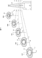
- FIG. 1 is a perspective view showing an entire configuration of an intraocular lens insertion device 1 (hereinafter, referred to as an insertion device 1).
- the insertion device 1 includes a cylindrical device main body 2, a distal tip 3, a lens holder 4 for holding an intraocular lens 7, a plunger 5, a lens presser 6, and a centering member. 8 and a spring 9.
- the tip 3 has a nozzle portion 32 connected to the apparatus main body 2.
- the lens holder 4 can be attached to the apparatus main body 2.
- the plunger 5 has a rod shape, and is configured to be inserted into the apparatus main body 2.
- the lens pressing portion 6 is provided behind the nozzle portion 32 in the tip 3.
- the centering member 8 is a member for positioning the center axis of the plunger 5 and is attached to the apparatus main body 2. Note that the lens holder 4 may be attached to the tip 3.
- the axial direction of the plunger 5 is defined as the front-back direction.
- the thickness direction of the intraocular lens 7 held by the lens holder 4 is defined as the up-down direction, and the direction perpendicular to both the front-rear direction and the up-down direction is defined as the left-right direction.
- the tip 3 side of the insertion device 1 is defined as a front side, and the opposite side is defined as a rear side.
- the lens pressing portion 6 side of the tip chip 3 is defined as an upper side, and the opposite side is defined as a lower side.
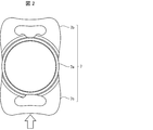
- FIG. 2 is a top view showing the configuration of the intraocular lens 7 mounted on the lens holder 4 of the insertion device 1.
- the intraocular lens 7 includes a lens portion 7a, a front support portion 7b, and a rear support portion 7c.
- the lens portion 7a is a lens portion that functions as a crystalline lens after insertion into the eye.
- the front support portion 7b and the rear support portion 7c have a function of supporting the lens portion 7a in the eye after insertion into the eye.
- the front support portion 7b and the rear support portion 7c are provided symmetrically with respect to the lens portion 7a, and have a flat plate shape.
- the front support portion 7b is formed so as to cover a front side surface of the lens portion 7a.
- the rear support portion 7c is formed so as to cover a rear side surface of the lens portion 7a.
- the intraocular lens 7 is a plate-type intraocular lens whose outer shape is substantially rectangular, and the rectangle is formed by a lens portion 7a, a front support portion 7b, and a rear support portion 7c.
- the lens portion 7a, the front support portion 7b, and the rear support portion 7c are made of a material having flexibility, and are formed to be flexibly deformable.
- a single piece type in which the lens portion 7a, the front support portion 7b, and the rear support portion 7c are integrally formed will be described as an example.
- the device main body 2 has a configuration in which the distal end tip 3 is engaged with the front, an annular enlarged portion 22 that can be gripped by an operator on the outer surface of the front end, and a flange that the operator holds by holding a finger on the outer surface of the rear end. And a holding portion 23 in a shape of a circle.
- the apparatus main body 2 is formed using a resin such as polycarbonate having impact resistance.
- the annular enlarged portion 22 is formed of, for example, a plurality of annular protrusions.
- the annular expanding portion 22 and the holding portion 23 may have any shape as long as they can perform required functions.
- the holding portion 23 may be formed by a protrusion or the like that allows a finger to be hooked, instead of a flange shape.
- the surgeon grasps the annular enlarged portion 22 with the other hand and holds the intraocular lens 7 in the order of the front support portion 7b, the lens portion 7a, and the rear support portion 7c. Release into the patient's eye.
- the provision of the annular enlarged portion 22 makes it easier for the surgeon to grasp the insertion instrument 1 and enhances the operability of the insertion instrument 1.
- the distal tip 3 has an emission portion 31 from which the intraocular lens 7 is emitted, a nozzle portion 32 whose inner diameter gradually decreases toward the front, and a rectangular portion 33 having a rectangular outer periphery with an open side surface. are doing.
- the distal tip 3 is connected to the device main body 2 by engaging the rectangular portion 33 with the device main body 2.
- a lens holding portion 6 is attached to the upper side near the entrance of the nozzle portion 32.
- the configuration for engaging the tip 3 with the apparatus main body 2 may be any configuration such as, for example, engagement between a locking claw and a locking hole.
- the tip 3 is formed using a resin such as polypropylene or polyamide having chemical resistance and flexibility.
- the insertion device 1 has a configuration in which the lens holder 4 holding the intraocular lens 7 can be attached.
- the insertion device 1 according to the present embodiment may have a form in which the lens holder 4 is separated or a form in which the lens holder 4 is attached.
- the surgeon inserts the lens holder 4 into the opening formed on the side surface of the rectangular portion 33.
- the rectangular part 33 can be said to be an installation part on which the lens holder 4 is installed. Note that the lens holder 4 may be inserted into the opening of the rectangular portion 33 before use of the insertion device 1, or may be inserted into the opening of the rectangular portion 33 when the insertion device 1 is used.
- the lens holder 4 has a housing part 41 that forms a housing space for housing the intraocular lens 7, and a knob part 42 provided to protrude laterally from the housing part 41.
- the accommodation section 41 has openings formed on both the front side and the rear side.
- the space inside the housing portion 41 and the space inside the nozzle portion 32 communicate with each other through an opening formed on the rear side of the housing portion 41.
- the operator grasps the knob 42 and inserts the lens holder 4 into an opening formed on the side surface of the rectangular portion 33, so that the intraocular lens 7 is inserted. 1 is attached.
- the lens holder 4 is formed using a resin such as polypropylene having chemical resistance.
- the plunger 5 includes a rear shaft portion 51, a pressing portion 52, and a center shaft portion 53.
- the rear side shaft portion 51 is located on the rearmost side of the plunger 5.
- the rear shaft portion 51 is a portion that is exposed to the outside when the plunger 5 is in the initial position where the plunger 5 is inserted into the apparatus main body 2.
- the rearward movement of the rear shaft 51 is restricted by a stopper provided at the rear end of the apparatus main body 2.
- the pressing portion 52 is formed in a flange shape on the peripheral surface on the rear side of the rear side shaft portion 51. The operator moves the plunger 5 toward the distal end by pushing the pressing portion 52 toward the apparatus main body 2.
- the center shaft 53 is connected to the front side of the rear shaft 51 and is a shaft having a smaller diameter than the rear shaft 51.
- a lens contact member 54 that contacts the rear support portion 7c of the intraocular lens 7 is attached to the distal end of the center shaft portion 53.
- the spring 9 is provided along the outer peripheral surface of the center shaft portion 53. Thereby, the reaction force is received from the spring 9 when the plunger 5 is pushed, and the intraocular lens 7 can be prevented from vigorously jumping out of the lens contact member 54 of the plunger 5.
- the position of the spring 9 is not particularly limited.
- the spring 9 may be disposed between the pressing portion 52 of the plunger 5 and the rear end of the apparatus main body 2, provided that the spring 9 receives a reaction force from the elastic member when the plunger 5 is pressed. Good.
- the plunger 5 When the plunger 5 is pushed from the initial position to the front-back direction from the initial position in a state where the plunger 5 is at the initial position, the plunger 5 passes through the opening formed on the rear side of the housing portion 41. Then, the lens contact member 54 at the tip of the plunger 5 comes into contact with the rear support portion 7c of the intraocular lens 7. Then, the plunger 5 further advances to the distal end side, passes through an opening formed in the front side of the housing section 41, and advances into the distal end tip 3. At this time, the intraocular lens 7 is folded in a concave shape while passing through the nozzle portion 32 of the tip 3. Next, the intraocular lens 7 reaches the emission unit 31 in a state where the intraocular lens 7 is folded. The intraocular lens 7 that has reached the emission unit 31 is inserted into the eye from the cut side of the emission unit 31 in the order of the front support unit 7b, the lens unit 7a, and the rear support unit 7c.
- a front support portion and a rear support portion are formed so as to extend in a curved manner from the side surface of the lens portion. It has a loop shape.
- the intraocular lens 7, which is the above-mentioned plate-type intraocular lens, is made of a material having flexibility as compared with the intraocular lens having the loop-shaped front support portion and the rear support portion. Therefore, when a plate-type intraocular lens 7 is inserted into the eye using a conventional intraocular lens insertion device equipped with an intraocular lens, the intraocular lens 7 may be damaged.
- An object of the insertion device 1 according to the present embodiment is to appropriately insert a plate-type intraocular lens 7 made of a flexible material into an eye without damaging the intraocular lens 7.
- the contact position of the plunger 5 in the intraocular lens 7 may deviate from the original contact position due to a mounting error of the intraocular lens 7 with respect to the lens holder 4 or the like. For this reason, there is a possibility that the plunger 5 rides on or slips into the intraocular lens 7.
- the intraocular lens 7 is made of a flexible material. Therefore, the intraocular lens 7 may be damaged and damaged by the plunger 5.
- the intraocular lens 7 is made of a flexible material, the intraocular lens 7 is easily deformed rearward from the contact position of the plunger 5 by the pushing operation by the plunger 5.
- a force for moving the intraocular lens 7 in a contact portion with the plunger 5 acts forward.
- a force remaining on the tapered surface of the nozzle portion 32 acts on the portion other than the contact portion due to friction with the tapered surface of the nozzle portion 32.
- the intraocular lens 7 passes through the nozzle portion 32 in a state where it is excessively extended rearward from the contact position with the plunger 5, and the intraocular lens 7 may be damaged.
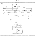
- FIG. 4 is a cross-sectional view showing a state when the lens contact member 54 of the plunger 5 has reached the opening 41a on the rear side of the accommodating portion 41, and 3002 in FIG. 3 is an enlarged view of 3001 in FIG. It is. 4 shows a configuration of the lens contact member 54, 4001 in FIG. 4 is a perspective view, 4002 in FIG. 4 is a top view, 4003 in FIG. 4 is a side view, and 4004 in FIG. Is a front view seen from the front side.
- the lens contact member 54 of the plunger 5 that contacts the intraocular lens 7 is made of an elastically deformable material that is softer than the central shaft portion 53 of the plunger 5 and that can be elastically deformed. Have been. Further, as the material forming the lens contact member 54, for example, silicone, silicone elastomer, or the like can be used.
- the lens contact member 54 is provided with a projection 54a protruding from the lateral side in the left-right direction.
- the lens abutting member 54 has an alligator-shaped crocodile structure 54b cut out larger than the vertical dimension (thickness direction) of the intraocular lens 7.
- the crocodile mouth structure 54b has a structure in which the intraocular lens 7 is vertically sandwiched at least in the housing portion 41 of the lens holder 4, and an upper slope portion 54c and a lower slope portion 54d that face each other in the vertical direction. Have.
- the lower slope portion 54d is formed of an inclined surface connected to the lower surface 54e of the lens contact member 54.
- no surface perpendicular to the lower surface 54e is interposed between the inclined surface of the lower slope portion 54d and the lower surface 54e.
- the structure of the “slope surface connected to the lower surface 54e of the lens contact member 54” here refers to the accuracy of the processing condition during the processing of the connection structure between the lower surface 54e and the slope surface of the lower slope portion 54d.
- a structure in which an R surface or the like is formed at a connection portion between the inclined surface of the lower slope portion 54d and the lower surface 54e is also included.
- the vertical dimension of the lens contact member 54 is greater than or equal to the vertical dimension of the rear opening 41a and the front opening 41b of the housing 41. More specifically, the vertical dimension of the lens contact member 54 is greater than or equal to the distance between the walls of the housing 41 that are opposed to each other in the vertical direction. Accordingly, when the lens contact member 54 is inserted into the housing portion 41, the lens abutment member 54 is elastically deformed so as to fit within the space between the vertically opposed walls of the housing portion 41. Then, due to this elastic deformation, the upper slope portion 54c and the lower slope portion 54d of the alligator structure 54b are elastically deformed so as to reduce the interval therebetween, and come into contact with the upper and lower surfaces of the intraocular lens 7.
- the intraocular lens 7 housed in the housing part 41 is sandwiched by the alligator structure 54b. Therefore, even if the mounting error of the intraocular lens 7 with respect to the lens holder 4 occurs, the displacement of the contact position of the plunger 5 in the intraocular lens 7 is eliminated. Therefore, according to the insertion device 1 according to the present embodiment, it is possible to prevent the plunger 5 from climbing onto the intraocular lens 7 or getting into the intraocular lens 7.
- the upper limit of the vertical dimension of the lens contact member 54 is such that the movement of the lens contact member 54 is hindered by the contact between the lens contact member 54 and the walls of the accommodating portion 41, the nozzle portion 32, and the discharge portion 31.
- the range can be set as appropriate depending on the material of the lens contact member 54, the dimensions of the alligator structure 54b, and the like, within a range not present.
- the lower slope portion 54d is formed of an inclined surface connected to the lower surface 54e of the lens contact member 54. Therefore, when the plunger 5 moves forward while the lens contact member 54 is in contact with the intraocular lens 7, the rear support portion 7c of the intraocular lens 7 moves on the lower slope portion 54d, and is smooth. In addition, the intraocular lens 7 easily fits in the crocodile mouth structure 54b. Therefore, the intraocular lens 7 can be more reliably held by the alligator structure 54b.
- the vertical dimension of the lens contact member 54 is preferably the distance between the vertically opposed walls that form the lumens of the discharge part 31 and the nozzle part 32 of the tip 3. Greater than or the same.
- the projection 54a of the lens contact member 54 functions as a stopper that restricts the extension and deformation of the intraocular lens 7 to the rear side.
- the extension deformation of the intraocular lens 7 toward the rear side can be said to be extension deformation of the intraocular lens 7 in the direction opposite to the pushing direction of the plunger 5.
- the intraocular lens 7 When the intraocular lens 7 is pushed into the tapered nozzle portion 32 and folded, a portion that is deformed rearward from the contact position with the plunger 5 is formed by a protrusion 54 a provided on the side surface of the lens contact member 54. Locked. Therefore, the deformation of the intraocular lens 7 from the contact position with the plunger 5 to the rear side is restricted by the projection 54a, and it is possible to prevent the intraocular lens 7 from passing through the nozzle portion 32 in an excessively extended state. Therefore, according to the insertion device 1 according to the present embodiment, the extension of the intraocular lens 7 in the nozzle portion 32 toward the rear side can be suppressed, and the intraocular lens 7 can be prevented from being damaged. .
- the size of the lens contact member 54 in the left-right direction is within a range in which the movement of the lens contact member 54 is not hindered by the contact between the lens contact member 54 and the walls of the accommodating portion 41, the nozzle 32, and the discharge portion 31.
- it can be appropriately set according to the material of the lens contact member 54, the size of the protrusion 54a, and the like.
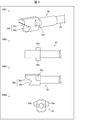
- FIG. 6 shows the lens pressing part 6 attached to the nozzle part 32
- 7001 in FIG. 7 is a bottom view seen from below
- 7002 in FIG. 7 is a cross-sectional view showing a cross section perpendicular to the front-rear direction. It is.
- the lens pressing portion 6 includes a plate-shaped rib portion 61 (projection portion) and a base portion 62 that supports the plate-shaped rib portion 61. , A shaft portion 63 and a leaf spring portion 64.
- the rotating mechanism of the plate-shaped rib portion 61 in the insertion device 1 has a configuration including at least the shaft portion 63 and the plate spring portion 64.
- the plate-shaped rib portion 61 is a protruding ridge protruding toward the lumen side of the nozzle portion 32 and extending in the front-rear direction (the pushing direction of the plunger 5) over a predetermined dimension.
- the lower end portion of the plate-shaped rib portion 61 is formed such that its shape is a downwardly convex single curve in the front-rear direction. Further, the plate-shaped rib portion 61 is arranged so as to abut on the plunger 5 and to contact at least the lens portion 7a of the intraocular lens 7 at the lower end.
- the shaft 63 is provided so as to protrude from the base 62 in the left-right direction, and is inserted into a bearing opening provided in the nozzle 32.
- the lens pressing part 6 is connected to the nozzle part 32 via a shaft part 63, and is rotatable around the shaft part 63 extending in the left-right direction.
- the leaf spring portion 64 has a plate shape bent in a forward convex shape, and is provided in contact with a predetermined plane of the nozzle portion 32.
- the leaf spring portion 64 is configured to bias the base portion 62 so that the base portion 62 rotates in a direction approaching the nozzle portion 32. Therefore, when the base 62 rotates about the shaft 63 in the direction away from the nozzle 32, the leaf spring 64 applies an urging force to the base 62 so as to move closer to the nozzle 32. .
- the central portion of the lens portion 7a of the intraocular lens 7 is in contact with the plate-like rib portion 61.
- the central portion of the intraocular lens 7 is positioned by the plate-shaped rib portion 61 near the entrance of the nozzle portion 32.
- the intraocular lens 7 is moved forward by the pushing operation of the plunger 5 in such a positioned state, the intraocular lens 7 is folded by the tapered surface of the nozzle portion 32 without a positional shift of the central portion. .
- the intraocular lens 7 that has passed through the lens holding portion 6 and moved forward is folded in a valley-folded state that is line-symmetric with respect to the center portion and convex toward the bottom surface of the nozzle portion 32. become.
- the plunger 5 is pushed into the nozzle part 32 in a state where the lens contact member 54 at the tip is in contact with the rear end of the intraocular lens 7. For this reason, when the intraocular lens 7 moves forward through the lens pressing portion 6, the lens surface of the intraocular lens 7 comes into contact with the plate-shaped rib portion 61 of the lens pressing portion 6. State, a state in which the lens contact member 54 is in contact with the plate-shaped rib portion 61 of the lens pressing portion 6, or a state in which the lens surface of the intraocular lens 7 and the lens contact member 54 are in contact with the plate-shaped rib portion 61 of the lens pressing portion 6. Both are in contact.
- the pressing force of the plunger 5 causes the plate-like rib portion 61 to pivot about the shaft portion 63 in a direction in which the lower end portion moves away from the bottom surface of the nozzle portion 32. And does not hinder the progress of the plunger 5.
- the lens surface of the intraocular lens 7 is in contact with the plate-shaped rib portion 61 of the lens pressing portion 6, the lens that moves forward when the plunger 5 is further pushed forward.
- the plate-shaped rib portion 61 may be rotated by the contact action between the surface and the lens pressing portion 6. That is, the plate-shaped rib 61 may rotate before the lens contact member 54 comes into contact with the plate-shaped rib 61.
- the plate-shaped rib portion 61 is moved by the urging force of the plate spring portion 64. It rotates in the direction approaching the bottom. Then, the lens holding unit 6 is returned to the initial position.
- the intraocular lens 7 is folded line-symmetrically and valley-folded with the central portion positioned by the plate-shaped rib portion 61. Therefore, the plate-type intraocular lens 7 is released from the release unit 31 without being damaged by the pushing operation by the plunger 5.
- the plate-shaped rib portion 61 is rotated in the pushing direction of the plunger 5 by the contact with the plunger 5 by the rotating mechanism including the shaft portion 63 and the plate spring portion 64. For this reason, even after the intraocular lens 7 has passed through the lens holder 6, the movement of the plunger 5 is not hindered by the lens holder 6. Therefore, the plunger 5 can be smoothly pushed in while the intraocular lens 7 is folded in a symmetrically trough manner at the nozzle portion 32.
- the protrusion extending in the front-rear direction protrudes toward the lumen side of the nozzle portion 32, and may have any configuration that positions the central portion of the intraocular lens 7 as described above.
- the present invention is not limited to the plate-like rib portion 21 shown in FIG.
- FIG. 6 is a perspective view showing an example of the configuration of the protruding portion.
- reference numeral 6001 denotes a configuration of the plate-like rib portion 61 shown in FIG. 5
- reference numeral 6002 in FIG. 6 and reference numeral 6003 in FIG. 6 shows still another configuration example of the projection shown in 6001 in FIG.
- two plate-shaped rib portions 61 are provided.
- the two plate-shaped ribs 61 protrude from the base 62 toward the lumen side of the nozzle portion 32 and extend in the front-rear direction (the direction in which the plunger 5 is pushed out) over a predetermined dimension so as to be parallel to each other. Further, the two plate-shaped rib portions 61 are arranged so as to be line-symmetric with respect to the symmetry axis of the nozzle portion 32.
- the number of the protrusions is not limited to two, such as the plate-like rib 61 shown in 6001 of FIG. As shown by 6002 in FIG. 6, the protrusion 61 a may be a single ridge protruding from the base 62 to the lumen side of the nozzle 32.
- the protrusion 61a has a width in the left-right direction such that the central portion of the intraocular lens 7 is positioned.
- the projection 61a shown by 6002 in FIG. 6 is solid.
- the protrusion is not limited to a solid structure, and may have a hollow structure.
- Reference numeral 6003 in FIG. 6 illustrates a configuration example of the protrusion 61b having a hollow structure.
- the protrusion 61b is formed as a concave groove that is recessed from the base 62a toward the lumen side of the nozzle portion 32.
- the protrusion 61b extends in the front-rear direction (extending direction of the plunger 5) over a predetermined dimension.
- the protrusion 61b has a width in the left-right direction such that the central portion of the intraocular lens 7 is positioned.
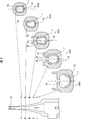
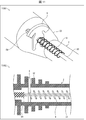
- the insertion device 1 is characterized by the shape of the tapered inner wall surface that forms the lumen of the nozzle part 32 because the intraocular lens 7 is folded line-symmetrically and folded in the nozzle part 32.
- 8001 to 8005 are views each showing a cross-sectional shape of the tapered inner wall surface 35 constituting the lumen 34 of the nozzle portion 32.
- Each of 9001 to 9005 in FIG. 9 is a diagram showing another cross-sectional shape of the tapered inner wall surface 35 forming the lumen 34 of the nozzle portion 32.
- the cross-sectional shapes perpendicular to the front-rear direction are, in order from the rear side to the front side, the II line cross-sectional shape, the II-II line cross-sectional shape, the III-III line cross-sectional shape, and the IV-
- the IV line cross-sectional shape and the VV line cross-sectional shape correspond to the cross-sectional shapes 8001 and 9001 to 8005 and 9005, respectively.
- the nozzle portion 32 includes a lumen 34, a tapered inner wall surface 35 forming the lumen 34, and a ridge 36.
- the ridge 36 is provided on the tapered inner wall surface 35 on the upper side, and protrudes downward.
- two convex ridges 36 are provided with a vertical axis of symmetry of the nozzle 32 interposed therebetween. These two ridges 36 are arranged to be line-symmetric with respect to the axis of symmetry of the nozzle 32.
- the protruding ridge portion 36 is provided so as to avoid at least the tip portion of the nozzle portion 32.
- the intraocular lens 7 moved to the nozzle portion 32 by the pushing operation of the plunger 5 is folded valley by the lens pressing portion 6 near the position and opening of the nozzle portion 32 and moves forward. Then, the valley-folded intraocular lens 7 moves forward while being folded by the action of the tapered inner wall surface 35.
- the traveling axis of the intraocular lens 7 may be shifted.
- the intraocular lens 7 whose traveling axis is displaced in this way rotates and moves along the tapered inner wall surface 35. As a result, there is a possibility that the intraocular lens 7 will not be folded due to the line-symmetric valley fold.
- the rotational movement of the intraocular lens 7 along the tapered inner wall surface 35 is restricted by the provision of the ridge 36 on the nozzle 32.
- the valley-folded intraocular lens 7 is moved forward by the plunger 5
- the left-right end of the intraocular lens 7 is formed on the tapered inner wall surface 35.
- the movement along is locked by the ridge 36.
- the locking of the end portion of the intraocular lens 7 by the convex ridge portion 36 is released in the vicinity of the tip end of the nozzle portion 32 where the convex ridge portion 36 is not provided.
- the intraocular lens 7 is folded line-symmetrically and valley-folded in the nozzle portion 32.
- the protruding ridge portion 36 is provided on the rear side of the front end of the lens pressing portion 6. Is preferred. In the vicinity of the inlet of the nozzle portion 32, the convex portion 36 does not necessarily need to be provided on the rear side of the lens pressing portion 6. The reason is that the left and right ends of the intraocular lens 7 do not reach the position of the convex portion 36 of the tapered inner wall surface 35 near the entrance of the nozzle portion 32.
- the cross-sectional shapes 8001 to 8005 of the tapered inner wall surface 35 forming the inner cavity 34 of the nozzle portion 32, which are perpendicular to the front-rear direction, are vertically long in the vertical direction.
- the cross-sectional shape of the tapered inner wall surface 35 can be appropriately set according to the dimensions of the intraocular lens 7, folding behavior, and the like, and is not limited to the cross-sectional shapes 8001 to 8005 shown in FIG.
- the cross-sectional shape of the tapered inner wall surface 35 may be cross-sectional shapes 9001 to 9005 horizontally long in the left-right direction as shown in FIG.
- the number of the ridges 36 is not particularly limited as long as the number is arranged symmetrically with respect to the axis of symmetry of the nozzle 32.
- a configuration provided with one protruding ridge portion 36a such as the cross-sectional shapes 10001 to 10005 shown in FIG. 10, may be used.
- the protruding ridge portion 36 a has a shape symmetrical with respect to the axis of symmetry of the nozzle portion 32, and is provided so as to avoid at least the tip portion of the nozzle portion 32.
- the nozzle portion 36a has a shape such that the width in the left-right direction decreases toward the tip end side of the nozzle portion 32. Even in the cross-sectional shapes 10001 to 10005 shown in FIG. 10, the intraocular lens 7 is folded line-symmetrically and valley in the nozzle portion 32.
- the centering member 8 is a member that restricts such rattling of the plunger 5.
- FIG. 11 shows the configuration of the centering member 8 attached to the annular enlarged portion 22
- 11011 in FIG. 11 is a perspective view
- 11002 in FIG. 11 is a sectional view
- 12 is a front view showing the configuration of the centering member 8 as viewed from the front side
- 12002 in FIG. 12 shows the configuration of the centering member 8 attached to the annular enlarged portion 22 and is perpendicular to the front-rear direction.
- the centering member 8 is provided on the annular enlarged portion 22 of the apparatus main body 2.
- the position of the centering member 8 in the apparatus main body 2 is not limited to the annular enlarged portion 22.
- the plunger 5 is attached to the centering member 8 such that the lens contact member 54 is located on the front side.
- the spring 9 is arranged on the rear side of the centering member 8. With such a configuration, the lens contact member 54 of the plunger 5 moves only forward of the centering member 8 and does not move rearward.
- the annular enlarged portion 22 is composed of a plurality of annular protrusions
- the centering member 8 is provided between the annular protrusions, as shown by 11002 in FIG.
- the centering member 8 has two lower locking claws 81, a plunger insertion portion 82, and an upper locking piece 83.
- the plunger insertion portion 82 is provided between the lower locking claw 81 and the upper locking piece 83, and the center shaft portion 53 of the plunger 5 is inserted.
- a through-hole through which the plunger insertion portion 82 can vertically penetrate is provided above the annular enlarged portion 22. Further, two through holes through which the lower locking claw 81 can penetrate are provided below the annular enlarged portion 22.
- the lower locking claw 81 penetrates through two through holes provided below the annular enlarged portion 22 and is locked by being hooked on the through hole from outside the annular enlarged portion 22.
- the upper locking piece 83 is abutted and locked from the outside to the edge of the upper through hole of the annular enlarged portion 22 through which the plunger insertion portion 82 penetrates.
- the lower locking claw 81 and the upper locking piece 83 are locked to the annular enlarged portion 22, so that the plunger insertion portion 82 is aligned with the advancing axis of the plunger 5. Therefore, when the plunger 5 is inserted into the plunger insertion portion 82, rattling in the left-right direction and the up-down direction is regulated even when a force is applied.
- the contact position of the plunger 5 in the intraocular lens 7 does not deviate from the advancing axis of the intraocular lens 7.
- the centering member 8 may be separate from the apparatus main body 2 or may be formed integrally with the apparatus main body 2.
- An intraocular lens insertion device is an intraocular lens insertion device to which a lens holder that holds an intraocular lens can be attached, wherein the intraocular lens insertion device abuts on the intraocular lens held by the lens holder.
- a distal end portion, and the distal end portion includes a stopper that regulates extension deformation of the intraocular lens in a direction opposite to a pushing direction of the plunger.
- the stopper is a projection provided on a side surface of the distal end portion.
- An intraocular lens insertion device is the intraocular lens insertion device according to aspect 1 or 2, wherein the distal end portion has a U-shaped crocodile mouth structure that sandwiches the intraocular lens in a thickness direction. Is preferred.
- the intraocular lens insertion device is the intraocular lens insertion tool according to aspect 3, wherein the crocodile mouth structure has a lower slope portion and an upper slope portion that face each other in a thickness direction of the intraocular lens, It is preferable that the lower slope portion is constituted by an inclined surface connected to a lower surface of the tip portion.
- An intraocular lens insertion device is an intraocular lens insertion device to which a lens holder that holds an intraocular lens can be attached, wherein the intraocular lens insertion device abuts on the intraocular lens held by the lens holder.
- a plate-shaped rib portion extending in a direction, and a rotating mechanism for rotating the plate-shaped rib portion in the pushing direction by abutting the plate-shaped rib portion with a lens surface of the intraocular lens and / or the plunger. , Is provided.
- An intraocular lens insertion device is an intraocular lens insertion device to which a lens holder that holds an intraocular lens can be attached, wherein the intraocular lens insertion device abuts on the intraocular lens held by the lens holder.
- the protrusion is a plate-like rib protruding toward a lumen side of the nozzle portion and extending in a pushing direction of the plunger.
- An intraocular lens insertion device is an intraocular lens insertion device to which a lens holder that holds an intraocular lens can be attached, wherein the intraocular lens insertion device abuts on the intraocular lens held by the lens holder.
- the ridge portion is disposed so as to be symmetric with respect to an axis of the nozzle portion, and at least avoids a tip portion of the nozzle portion. It is preferable that the configuration is provided.
- the intraocular lens insertion device according to aspect 10 of the present invention is preferably configured such that, in aspect 9, at least two of the ridges are arranged symmetrically with respect to the axis of the nozzle portion. .
- An intraocular lens insertion device is an intraocular lens insertion device including a cylindrical main body, and capable of attaching a lens holder holding an intraocular lens to an end surface side of the main body, wherein the lens A plunger which is inserted into and retracted from the main body in order to push the intraocular lens in contact with the intraocular lens held by the holder, and the intraocular lens while folding the intraocular lens extruded by the plunger And a nozzle portion for discharging the fluid, wherein the main body is provided with a centering member for centering the plunger.
- An intraocular lens insertion device is the intraocular lens insertion device according to any one of aspects 5 to 7, wherein the rotating mechanism is provided with a shaft protruding left and right from a base supporting the plate-shaped rib. And a plate spring for urging the base so that the base rotates in a direction approaching the nozzle.
- Intraocular lens insertion device 2 Apparatus main body 3 Tip tip 4 Lens holder 5 Plunger 7 Intraocular lens 8 Centering member 22 Annular enlarged portion 32 Nozzle portion 35 Tapered inner wall surface 36, 36a Convex ridge 41 Housing 41a, 41b Opening 54 Lens contact member 54a Projection ( Stopper) 54b Alligator structure 54c Upper slope 54d Lower slope 54e Lower surface 61 Plate-shaped rib (projection) 62 Base 63 Shaft 64 Plate spring 81 Lower locking claw 82 Plunger insertion part 83 Upper locking piece
Landscapes
- Health & Medical Sciences (AREA)
- Ophthalmology & Optometry (AREA)
- Cardiology (AREA)
- Oral & Maxillofacial Surgery (AREA)
- Transplantation (AREA)
- Engineering & Computer Science (AREA)
- Biomedical Technology (AREA)
- Heart & Thoracic Surgery (AREA)
- Vascular Medicine (AREA)
- Life Sciences & Earth Sciences (AREA)
- Animal Behavior & Ethology (AREA)
- General Health & Medical Sciences (AREA)
- Public Health (AREA)
- Veterinary Medicine (AREA)
- Prostheses (AREA)
Abstract
L'objectif de la présente invention est d'insérer de manière appropriée une lentille intraoculaire de type plaque qui est formée à partir d'un matériau souple dans un œil sans endommager la lentille intraoculaire. Selon la présente invention, un instrument d'insertion (1) comporte un piston (5) qui comprend un élément de contact de lentille (54) qui est formé à partir d'un matériau élastiquement déformable et est destiné à entrer en contact avec une lentille intraoculaire (7). L'élément de contact de lentille (54) comprend des saillies (54a) qui limitent la déformation d'allongement de la lentille intraoculaire (7) à la fois dans la direction dans laquelle le piston (5) est poussé vers l'extérieur et dans la direction opposée.
Priority Applications (4)
| Application Number | Priority Date | Filing Date | Title |
|---|---|---|---|
| JP2020535786A JP7407113B2 (ja) | 2018-08-07 | 2019-08-06 | 眼内レンズ挿入器具 |
| EP19848023.8A EP3834775A4 (fr) | 2018-08-07 | 2019-08-06 | Instrument d'insertion de lentille intraoculaire |
| JP2023213200A JP7730881B2 (ja) | 2018-08-07 | 2023-12-18 | 眼内レンズ挿入器具 |
| JP2025135886A JP2025160524A (ja) | 2018-08-07 | 2025-08-18 | 眼内レンズ挿入器具 |
Applications Claiming Priority (2)
| Application Number | Priority Date | Filing Date | Title |
|---|---|---|---|
| JP2018-148879 | 2018-08-07 | ||
| JP2018148879 | 2018-08-07 |
Publications (1)
| Publication Number | Publication Date |
|---|---|
| WO2020032023A1 true WO2020032023A1 (fr) | 2020-02-13 |
Family
ID=69414856
Family Applications (1)
| Application Number | Title | Priority Date | Filing Date |
|---|---|---|---|
| PCT/JP2019/030897 Ceased WO2020032023A1 (fr) | 2018-08-07 | 2019-08-06 | Instrument d'insertion de lentille intraoculaire |
Country Status (3)
| Country | Link |
|---|---|
| EP (1) | EP3834775A4 (fr) |
| JP (3) | JP7407113B2 (fr) |
| WO (1) | WO2020032023A1 (fr) |
Cited By (2)
| Publication number | Priority date | Publication date | Assignee | Title |
|---|---|---|---|---|
| CN116322571A (zh) * | 2020-09-25 | 2023-06-23 | 卡尔蔡司医疗技术股份公司 | 用于注入器的柱塞以及注入器 |
| US20230310144A1 (en) * | 2022-04-05 | 2023-10-05 | JelliSee Ophthalmics Inc. | Intraocular lens insertion device |
Families Citing this family (1)
| Publication number | Priority date | Publication date | Assignee | Title |
|---|---|---|---|---|
| US12575925B2 (en) | 2022-11-07 | 2026-03-17 | Bausch + Lomb Ireland Limited | Intraocular lens injector apparatus |
Citations (7)
| Publication number | Priority date | Publication date | Assignee | Title |
|---|---|---|---|---|
| JPS529819B2 (fr) | 1973-01-31 | 1977-03-18 | ||
| JPS5236638B2 (fr) | 1973-03-26 | 1977-09-17 | ||
| JPS5415452B2 (fr) | 1974-12-13 | 1979-06-14 | ||
| JPS63197453A (ja) * | 1986-11-07 | 1988-08-16 | ザ・クーパー・カンパニー・インク | 圧縮性眼内レンズを眼に挿入する器具および方法 |
| JP2000516488A (ja) * | 1996-08-02 | 2000-12-12 | スター・サージカル・カンパニー,インコーポレイテッド | 横方向に蝶番が設けられたレンズカートリッジを有する変形可能な眼内レンズ注入装置 |
| JP2012030128A (ja) * | 2004-12-29 | 2012-02-16 | Bausch & Lomb Inc | プレロード式iol挿入装置および方法 |
| JP2012105736A (ja) * | 2010-11-15 | 2012-06-07 | Nidek Co Ltd | 眼内レンズ挿入器具 |
Family Cites Families (14)
| Publication number | Priority date | Publication date | Assignee | Title |
|---|---|---|---|---|
| US5772666A (en) * | 1992-09-30 | 1998-06-30 | Staar Surgical Company, Inc. | Deformable intraocular lens injecting apparatus with deformable tip plunger |
| JP3412106B2 (ja) * | 1994-07-07 | 2003-06-03 | キヤノンスター株式会社 | 変形可能な眼内レンズの挿入器具 |
| JP3412107B2 (ja) * | 1994-07-18 | 2003-06-03 | キヤノンスター株式会社 | 変形可能な眼内レンズの挿入器具 |
| JP3779819B2 (ja) * | 1997-08-11 | 2006-05-31 | キヤノンスター株式会社 | 眼内挿入用レンズの挿入器具 |
| US6723104B2 (en) * | 2002-03-13 | 2004-04-20 | Advanced Medical Optics, Inc. | IOL insertion apparatus and method for using same |
| JP2006006817A (ja) * | 2004-06-29 | 2006-01-12 | Canon Star Kk | 眼内挿入用レンズの挿入器具 |
| US9687340B2 (en) * | 2010-08-24 | 2017-06-27 | Abbott Medical Optics Inc. | Protective cap for an insertion device and other insertion device features |
| DE102011101940B4 (de) * | 2011-05-18 | 2014-01-02 | Iolution Gmbh | Injektor zum Implantieren einer Intraokularlinse |
| US20130245634A1 (en) * | 2011-12-23 | 2013-09-19 | Kyle Brown | Plunger system for intraocular lens surgery |
| CA2871046C (fr) * | 2012-04-20 | 2020-02-25 | Vijay Gulati | Injecteur precharge destine a etre utilise avec une lentille intraoculaire |
| JP6439303B2 (ja) * | 2014-07-14 | 2018-12-19 | 株式会社ニデック | 眼内レンズ挿入器具 |
| EP3590469B1 (fr) * | 2015-03-30 | 2024-06-05 | Nidek Co., Ltd. | Instrument d'injection de lentille intraoculaire |
| US11033382B2 (en) * | 2016-06-28 | 2021-06-15 | Hoya Corporation | Intraocular lens injector |
| KR102445286B1 (ko) * | 2016-07-07 | 2022-09-19 | 이올루션 게엠베하 | 안구내 렌즈를 이식하는 인젝터를 위한 카트리지 |
-
2019
- 2019-08-06 JP JP2020535786A patent/JP7407113B2/ja active Active
- 2019-08-06 WO PCT/JP2019/030897 patent/WO2020032023A1/fr not_active Ceased
- 2019-08-06 EP EP19848023.8A patent/EP3834775A4/fr active Pending
-
2023
- 2023-12-18 JP JP2023213200A patent/JP7730881B2/ja active Active
-
2025
- 2025-08-18 JP JP2025135886A patent/JP2025160524A/ja active Pending
Patent Citations (7)
| Publication number | Priority date | Publication date | Assignee | Title |
|---|---|---|---|---|
| JPS529819B2 (fr) | 1973-01-31 | 1977-03-18 | ||
| JPS5236638B2 (fr) | 1973-03-26 | 1977-09-17 | ||
| JPS5415452B2 (fr) | 1974-12-13 | 1979-06-14 | ||
| JPS63197453A (ja) * | 1986-11-07 | 1988-08-16 | ザ・クーパー・カンパニー・インク | 圧縮性眼内レンズを眼に挿入する器具および方法 |
| JP2000516488A (ja) * | 1996-08-02 | 2000-12-12 | スター・サージカル・カンパニー,インコーポレイテッド | 横方向に蝶番が設けられたレンズカートリッジを有する変形可能な眼内レンズ注入装置 |
| JP2012030128A (ja) * | 2004-12-29 | 2012-02-16 | Bausch & Lomb Inc | プレロード式iol挿入装置および方法 |
| JP2012105736A (ja) * | 2010-11-15 | 2012-06-07 | Nidek Co Ltd | 眼内レンズ挿入器具 |
Cited By (4)
| Publication number | Priority date | Publication date | Assignee | Title |
|---|---|---|---|---|
| CN116322571A (zh) * | 2020-09-25 | 2023-06-23 | 卡尔蔡司医疗技术股份公司 | 用于注入器的柱塞以及注入器 |
| CN116322571B (zh) * | 2020-09-25 | 2024-04-12 | 卡尔蔡司医疗技术股份公司 | 用于注入器的柱塞以及注入器 |
| US20230310144A1 (en) * | 2022-04-05 | 2023-10-05 | JelliSee Ophthalmics Inc. | Intraocular lens insertion device |
| US11950998B2 (en) * | 2022-04-05 | 2024-04-09 | JelliSee Ophthalmics Inc. | Intraocular lens insertion device |
Also Published As
| Publication number | Publication date |
|---|---|
| JP2024023705A (ja) | 2024-02-21 |
| EP3834775A4 (fr) | 2022-08-31 |
| JP7407113B2 (ja) | 2023-12-28 |
| EP3834775A1 (fr) | 2021-06-16 |
| JPWO2020032023A1 (ja) | 2021-08-10 |
| JP2025160524A (ja) | 2025-10-22 |
| JP7730881B2 (ja) | 2025-08-28 |
Similar Documents
| Publication | Publication Date | Title |
|---|---|---|
| JP7730881B2 (ja) | 眼内レンズ挿入器具 | |
| JP5221949B2 (ja) | 眼内レンズ挿入用器具 | |
| JP5236637B2 (ja) | 眼内レンズ挿入器具及び眼内レンズ挿入装置 | |
| JP6278701B2 (ja) | 眼内レンズ用インジェクタ | |
| JP4877643B2 (ja) | 眼内レンズ挿入用器具 | |
| JP2007307082A (ja) | 眼内挿入用レンズの挿入器具 | |
| EP2263573A2 (fr) | Paquet de pinces pour appareil à application de pinces | |
| JP2010057767A (ja) | 眼内レンズ挿入器具 | |
| CN114652386A (zh) | 夹具输送装置 | |
| JP4585049B2 (ja) | フード取付治具 | |
| JP4997246B2 (ja) | 使い捨てカートリッジ | |
| KR20080031411A (ko) | 필기 기구의 잉크 용기에 접근하기 위한 신속-해제 기구 | |
| JP2006141623A (ja) | クリップ | |
| JP2010069292A (ja) | クリップパッケージ | |
| JP5233008B2 (ja) | カッターナイフ | |
| JP4990191B2 (ja) | シフトレバー装置 | |
| JP4997247B2 (ja) | 使い捨てカートリッジ | |
| JP5865060B2 (ja) | 固定装置 | |
| JP7232253B2 (ja) | 眼内レンズ挿入器具 | |
| JP7086590B2 (ja) | 眼内レンズ用インジェクタ | |
| CN109715068B (zh) | 穿刺针盒和供其安装的穿刺器具 | |
| JP4557938B2 (ja) | 眼内レンズの挿入器具 | |
| JP3438676B2 (ja) | クリップ装着器 | |
| JP6676899B2 (ja) | 穿刺器具 | |
| JP3678356B2 (ja) | アシストグリップの取付構造 |
Legal Events
| Date | Code | Title | Description |
|---|---|---|---|
| 121 | Ep: the epo has been informed by wipo that ep was designated in this application |
Ref document number: 19848023 Country of ref document: EP Kind code of ref document: A1 |
|
| ENP | Entry into the national phase |
Ref document number: 2020535786 Country of ref document: JP Kind code of ref document: A |
|
| NENP | Non-entry into the national phase |
Ref country code: DE |
|
| ENP | Entry into the national phase |
Ref document number: 2019848023 Country of ref document: EP Effective date: 20210309 |