WO2020039902A1 - コルセット - Google Patents
コルセット Download PDFInfo
- Publication number
- WO2020039902A1 WO2020039902A1 PCT/JP2019/030641 JP2019030641W WO2020039902A1 WO 2020039902 A1 WO2020039902 A1 WO 2020039902A1 JP 2019030641 W JP2019030641 W JP 2019030641W WO 2020039902 A1 WO2020039902 A1 WO 2020039902A1
- Authority
- WO
- WIPO (PCT)
- Prior art keywords
- contact portion
- corset
- main body
- contact
- frame
- Prior art date
- Legal status (The legal status is an assumption and is not a legal conclusion. Google has not performed a legal analysis and makes no representation as to the accuracy of the status listed.)
- Ceased
Links
Images


Classifications
-
- A—HUMAN NECESSITIES
- A41—WEARING APPAREL
- A41D—OUTERWEAR; PROTECTIVE GARMENTS; ACCESSORIES
- A41D13/00—Professional, industrial or sporting protective garments, e.g. surgeons' gowns or garments protecting against blows or punches
- A41D13/05—Professional, industrial or sporting protective garments, e.g. surgeons' gowns or garments protecting against blows or punches protecting only a particular body part
-
- A—HUMAN NECESSITIES
- A61—MEDICAL OR VETERINARY SCIENCE; HYGIENE
- A61F—FILTERS IMPLANTABLE INTO BLOOD VESSELS; PROSTHESES; DEVICES PROVIDING PATENCY TO, OR PREVENTING COLLAPSING OF, TUBULAR STRUCTURES OF THE BODY, e.g. STENTS; ORTHOPAEDIC, NURSING OR CONTRACEPTIVE DEVICES; FOMENTATION; TREATMENT OR PROTECTION OF EYES OR EARS; BANDAGES, DRESSINGS OR ABSORBENT PADS; FIRST-AID KITS
- A61F5/00—Orthopaedic methods or devices for non-surgical treatment of bones or joints; Nursing devices ; Anti-rape devices
- A61F5/01—Orthopaedic devices, e.g. long-term immobilising or pressure directing devices for treating broken or deformed bones such as splints, casts or braces
- A61F5/02—Orthopaedic corsets
Definitions
- the present disclosure relates to a corset, and particularly relates to a corset used for lumbar spine disease and the like.
- corset In lumbar spine disease, a trunk orthosis (corset) that supports and fixes the lumbar spine is used.
- the corset when worn, increases the internal pressure of the abdominal cavity, thereby supporting the anterior spine and reducing the load on the lumbar spine. For this reason, a normal corset compresses the abdomen and the lumbar spine, restricting the movement of the lumbar region and fixing the trunk.
- a stretchable belt is wound around the trunk to compress and fix.
- a normal corset gives the wearer great discomfort because the lower abdomen is squeezed. In addition, it may interfere with daily life such as eating and sitting.
- An object of the present disclosure is to realize a corset that can fix the trunk without relying on compression of the lower abdomen.
- One aspect of the corset of the present disclosure is a frame mounted on a torso of a wearer, and a first abutment provided on the frame and abutting on a position of a lumbar vertebra when the frame is mounted on the torso of the wearer. And a second contact portion and a third contact portion that contact the positions of the left and right hip bones, respectively, and the torso of the wearer is connected to the first contact portion, the second contact portion, and the second contact portion. Three points are supported by three contact portions.
- the lumbar spine can be dispersed and supported by the lumbar bone, and sufficient lumbar spine support and fixation can be achieved while significantly reducing discomfort during mounting due to compression of the lower abdomen. It becomes possible.
- the frame includes a main body that is a C-shaped cylindrical body having a slit-shaped opening extending in the axial direction, and includes a first contact part, a second contact part, and a second contact part.
- the contact portion 3 may be provided on the inner surface of the main body.
- the frame may include an adjustment unit that adjusts the interval between the slit-shaped openings of the main body.
- the frame has two wing portions provided so as to protrude downward from the lower end portion of the main body portion, and the second contact portion and the third contact portion are wing portions. Each part may be provided. With such a configuration, the corset is hardly displaced, and the trunk can be supported and fixed more stably.
- the second contact portion and the third contact portion are provided at the center of the wing portion. With this configuration, the trunk can be supported and fixed more stably.
- the first contact portion can be brought into contact with any position from the third lumbar vertebra to the fifth lumbar vertebra of the wearer. With such a configuration, it is possible to cope with many lumbar spine diseases.
- the frame includes a first portion including a first contact portion, a second portion including a second contact portion, and a third portion including a third contact portion.
- the trunk can be fixed without depending on the compression of the lower abdomen, and the discomfort at the time of wearing can be greatly reduced.
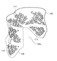
- FIG. 1 is a perspective view showing a corset according to one embodiment.
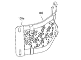
- FIG. 2 is a perspective view showing a corset cylinder according to one embodiment.
- FIG. 3 is a perspective view showing a plate of the corset according to one embodiment.
- FIG. 4 is a side view showing an example of mounting a corset according to one embodiment.
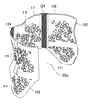
- FIG. 5 is a perspective view showing a modification of the housing.
- the corset of the present embodiment comes into contact with the frame 101 to be mounted on the torso of the wearer and the position of the lumbar vertebra when the frame 101 is mounted on the torso of the wearer.
- the wearer's trunk (torso) is supported at three points by a first contact portion 111, a second contact portion 112, and a third contact portion 113.
- the corset of the present embodiment supports the left and right greater trochanters and the lumbar vertebra at three points, and disperses a part of the force applied to the lumbar vertebra to the left and right greater trochanters to reduce the load on the lumbar vertebra. To reduce. Therefore, the trunk can be supported without compressing the lower abdomen, and discomfort due to compression of the lower abdomen can be significantly reduced.
- the frame 101 includes a main body 102 that is a C-shaped cylindrical body having a slit-shaped opening 102 a extending in the height direction, and protrudes below the main body 102. And two substantially triangular wing portions 108.
- the main body 102 is mounted on the body with the opening 102a on the abdomen side.
- the main body 102 preferably has a constricted shape at the center in the circumferential direction and at the center in the height, corresponding to the shape of the torso of a person.
- the first contact portion 111, the second contact portion 112, and the third contact portion 113 are provided on the inner peripheral surface of the frame 101, respectively, and contact the corresponding body surface of the body.
- the first contact portion 111 is provided at the center in the circumferential direction at the upper part of the main body portion 102, and the second contact portion 112 and the third contact portion 113 are respectively provided at the center of the wing portion 108. It is provided near the section.
- the frame 101 is formed of a hard material capable of supporting the trunk at three points. Further, it is preferable that the opening 102a has such flexibility that the opening 102a can be widened and attached to the trunk. Specifically, it can be formed of a resin such as polyethylene, polypropylene, polyester, polyamide, polyvinyl chloride, polycarbonate, polyamide elastomer, and polyimide. For this reason, the frame 101 becomes independent in a state where it is not mounted, and the relative positional relationship of the three contact portions does not change.
- a resin such as polyethylene, polypropylene, polyester, polyamide, polyvinyl chloride, polycarbonate, polyamide elastomer, and polyimide.
- the frame 101 adjusts the interval between the openings 102a of the main body 102, and increases the force with which the second abutment portion 112 and the third abutment portion 113 abut on the left and right greater trochanters of the femur.
- It has an adjusting unit 103 that adjusts and fixes the position of the main body 102 with respect to the trunk.
- the adjustment unit 103 includes a plate 105 that covers the opening 102a of the main body 102, and a belt 106 that connects the plate 105 and the main body 102. By tightening the belt 106, the C-shaped main body 102 is deformed, so that the radial gap between the second contact portion 112 and the third contact portion 113 can be adjusted.
- the plate 105 does not press the lower abdomen to increase the internal pressure of the abdominal cavity, but adjusts the interval between the second contact portion 112 and the third contact portion 113 so as to adjust the left and right thighs. It is intended to abut on the greater trochanter with moderate force. Thereby, a part of the force applied to the lumbar vertebra is received by the first contact portion 111 and can be dispersed to the lumbar bone through the second contact portion 112 and the third contact portion 113. Further, it is possible to prevent the mounting position of the frame 101 from being shifted or the frame 101 from coming off due to the movement of the wearer.
- the plate 105 does not need to be in close contact with the body surface of the wearer, and an appropriate gap can be provided between the plate 105 and the body surface. By providing a gap between the plate 105 and the body surface, it is possible to make it difficult for the wearer's muscular strength to decrease due to relying on the plate 105 as a support.
- the plate 105 has step portions 105a on both sides, and the circumferential length of a portion between the step portions 105a in the plate 105 is larger than the circumferential length of the opening portion 102a of the main body portion 102. Designed to be a little shorter. For this reason, when the belt 106 is tightened, the main body 102 is deformed to a position where the step portion 105a and the end of the main body 102 are in contact with each other, and the distance between the second contact portion 112 and the third contact portion 113 is reduced. Become smaller.
- the second contact portion 112 and the third contact portion 113 are not deformed any more, so that the force of the second contact portion 112 and the third contact portion 113 contacting the hip bone is not too large, and the plate 105 does not compress the abdomen.
- a configuration in which the step portion 105a is not provided may be adopted.
- the plate 105 and the main body 102 may have mutually complementary inclined surfaces or curved surfaces, and the portions may be brought into contact with each other to prevent over-closing.
- the belt 106 connecting the plate 105 and the main body 102 has a hook-and-loop fastener, so that the length can be easily adjusted and the plate 105 can be easily removed.
- the adjustment of the length of the belt 106 may be realized by any configuration, for example, by a lock strap or the like.
- one end of the plate 105 may be fixed to the main body 102 by a hinge or the like, and the other end may be connected to the main body 102 by a belt or the like whose length can be adjusted.
- each of the plate 105 and the main body 102 may be provided with an adjustable-length belt or the like having a buckle that engages with each other, and the plate 105 and the main body 102 may be connected using this.
- the operation of fixing and adjusting the plate 105 can be performed in front of the wearer's body.
- the wearer can operate without twisting the body sideways, so that even a wearer who has a symptom such as low back pain and has difficulty twisting the body sideways can easily use the plate 105. Fixing and adjustment can be facilitated.
- the plate 105 and the main body 102 can be connected in an adjustable manner, not only a belt but also a string or a wire can be used.
- a latch mechanism and a dial such as those used for tightening shoelaces, can be provided with an adjusting mechanism that can adjust the length of the string or wire by turning the dial.
- the plate 105 and the main body 102 may be connected by using a snap button, a key hook, or the like.
- the adjustment unit may be configured to have no plate.
- both ends of the opening 102a may be directly connected by a belt or the like whose length is adjustable.
- a plate it is preferable to use a belt having a certain width, but a thin belt, a string, a wire, or the like may be used.
- the main body 102 is integrally formed.
- the integral molding facilitates the formation of the main body 102.
- the main body 102 can be formed by connecting a plurality of members. In this case, the main body 102 can be disassembled, which facilitates storage.
- the main body 102 is divided into a first portion including the first contact portion 111, a second portion including the second contact portion 112, and a third portion including the third contact portion 113.
- the first portion, the second portion, and the third portion may be provided with connecting portions, respectively, so that they can be integrally assembled.
- the connecting portion may be, for example, a concave portion and a convex portion which are provided at a side end portion of each portion and are fitted to each other.
- a hook-and-loop fastener may be attached to a side end portion of each portion, and the attached hook-and-loop fasteners may connect each other.
- the first portion 121 is not directly connected to the second portion 122 and the third portion 123 but is connected via a band-shaped connecting member 124 made of a flexible mesh cloth or the like. You can also. In this way, even when the respective parts are connected to each other, the parts can be folded and stored at the connecting member 124.
- FIG. 5 shows an example in which both sides of the connecting member 124 are fixed portions, and the fixed portions are fixed to the respective portions by adhesion or fusion so that the three portions are not separated from each other. With this configuration, the three portions are not connected by mistake, and the three portions can be prevented from being inadvertently separated during use and the positional relationship between the three portions can be prevented from shifting.
- the three parts may be configured to be separable from each other.
- FIG. 5 shows an example in which one belt-shaped connecting member 124 is continuously connected from the upper end to the lower end of each part.
- the length of the connecting member extends from the upper end to the lower end of each part. It is not necessary.
- a plurality of short connecting members may be arranged at intervals to connect each part.
- the connecting member 124 is not limited to the mesh cloth, and can be formed of a material that is more flexible than the first portion 121, the second portion 122, and the third portion 123.
- the main body 102 can be divided into three or more parts.
- the first contact portion 111 is a convex portion provided on the inner surface of the main body portion, and the second contact portion 112 and the third contact portion 113 are provided on the inner surface of each wing portion 108. It is a provided curved surface. It is preferable that each contact portion is designed to contact a necessary portion as a surface in order to suppress occurrence of pain or the like at the contact portion. In addition, when the contact portion is designed not for exclusive use of an individual but for general use, it is preferable that each contact portion is expanded to a range that can absorb the individual difference in the contact position.
- the first contact portion 111 is brought into contact with that position.
- each wing portion 108 has a substantially triangular shape whose width gradually decreases downward, and the second contact portion 112 and the second contact portion 112 whose central portions abut against the greater trochanter of the wearer. 3 is provided so as to be the contact portion 113.
- the shape of the wing portion 108 is not limited to a substantially triangular shape as long as it can cover the iliac bone, and may be a square shape, a semicircular shape, or the like.
- the trunk can be more stably supported and fixed.
- the second contact portion 112 and the third contact portion 113 may be provided anywhere on the wing portion 108, and may be provided at the tip of the wing portion 108, for example.
- the wing portion 108 can be formed integrally with the main body portion 102, but can also be formed separately from the main body portion 102 and attached to the main body portion 102 later.
- the second contact portion and the third contact portion may be provided so that the entire main body 102 extends downward without providing the wing portion 108.
- the movement of the body can be made more difficult to hinder than when the entire main body 102 extends to the position of the greater trochanter of the femur.
- first contact portion 111, the second contact portion 112, and the third contact portion 113 on the inner surface of the frame 101 need only be in contact with the body surface of the wearer, and the other portions are in contact with the body surface. You don't have to. However, a portion that contacts the body surface other than the first contact portion 111, the second contact portion 112, and the third contact portion 113 may be generated. For example, when the second abutment portion 112 and the third abutment portion 113 abut on the greater trochanter of the femur, the fourth and fifth abutments on the upper posterior upper iliac spine or the upper anterior upper iliac spine. Can be provided.
- the frame 101 has a plurality of openings.
- the openings can be freely arranged as long as the required strength can be maintained. Further, in the present embodiment, an example is shown in which the opening exerts a design, but the shape of the opening is not limited as long as air permeability can be ensured.
- the main body 102 has a configuration in which a C-shaped upper band provided with the first contact portion 111 and a C-shaped lower band connected to the wing 108 are connected by a plurality of columnar portions. You can also. In this case, one or more C-shaped intermediate bands may be provided between the upper band and the lower band.
- the corset of the present embodiment can tolerate individual differences in the body shape of the wearer to some extent, it is possible to apply it to most wearers by preparing several types having different diameters and heights of the main body 102.
- the position of each contact portion can be designed according to the body type of the wearer.
- the positions of the lumbar vertebra and the lumbar bone can be specified from, for example, an X-ray photograph or a CT photograph of the waist of the wearer, and the lumbar spine and the lumbar can be designed accordingly.
- the corset of the present embodiment has a hard frame, unlike a conventional hard corset in which a fracture is fixed by pressing the entire abdomen, the first abutment that contacts the position of the lumbar vertebra is provided.
- the trunk In order to support and fix at the three points of the contact part and the second contact part and the third contact part that contact the position of the greater trochanter of the left and right femurs, respectively, the trunk is not pressed by the lower abdomen. It can be fixed and discomfort at the time of mounting can be greatly reduced.
- the conventional rigid corset is pressed and fixed in accordance with the body surface, it is necessary to increase the area of the corset.
- the corset of the present disclosure can fix the trunk without relying on compression of the lower abdomen, and is useful as a corset used in lumbar spine disease and the like.
Landscapes
- Health & Medical Sciences (AREA)
- General Health & Medical Sciences (AREA)
- Engineering & Computer Science (AREA)
- Animal Behavior & Ethology (AREA)
- Biomedical Technology (AREA)
- Heart & Thoracic Surgery (AREA)
- Vascular Medicine (AREA)
- Life Sciences & Earth Sciences (AREA)
- Orthopedic Medicine & Surgery (AREA)
- Nursing (AREA)
- Public Health (AREA)
- Veterinary Medicine (AREA)
- Physical Education & Sports Medicine (AREA)
- Textile Engineering (AREA)
- Orthopedics, Nursing, And Contraception (AREA)
Abstract
コルセットは、装着者の胴部に装着されるフレーム101と、フレーム101に設けられ、フレーム101を装着者の胴部に装着した際に、腰椎の位置に当接する第1の当接部111並びに左右の大腿骨大転子の位置にそれぞれ当接する第2の当接部112及び第3の当接部113とを備えている。コルセットは、装着者の胴部を、第1の当接部111、第2の当接部112及び第3の当接部113により3点支持する。
Description
本開示はコルセットに関し、特に腰椎疾患等において使用するコルセットに関する。
腰椎疾患においては、腰椎部を支持、固定する体幹装具(コルセット)が用いられる。コルセットは、装着することにより腹腔の内圧を高め、これにより脊柱前方を支えて腰椎にかかる負荷を軽減する。このため、通常のコルセットは腹部及び腰椎部を圧迫して腰部の動きを制限し体幹を固定する。
通常のコルセットはある程度伸縮性のあるベルトを体幹に巻き付けて、圧迫と固定とを行う。通常のコルセットは、下腹部が圧迫されるため、装着者に大きな不快感を与える。また、食事や起坐などの日常生活の障害となる場合もある。
不快感や日常生活の障害を取り除くために、プレート等の硬質の構造を組合せたり、胸部にも支点を設けたりすることが検討されている(例えば、特許文献1を参照。)。
しかしながら、その原理上、従来のコルセットは下腹部を圧迫せざるを得ない。このため、装着時の不快感等を取り除く効果は極めて限定的である。
本開示の課題は、下腹部の圧迫によらずに体幹を固定することが可能なコルセットを実現できるようにすることである。
本開示のコルセットの一態様は、装着者の胴部に装着されるフレームと、フレームに設けられ、フレームを装着者の胴部に装着した際に、腰椎の位置に当接する第1の当接部並びに左右の腰骨の位置にそれぞれ当接する第2の当接部及び第3の当接部とを備え、装着者の胴部を、第1の当接部、第2の当接部及び第3の当接部により3点支持する。
このような構成とすることにより、腰椎にかかる力を腰骨に分散させて支えることができ、下腹部の圧迫による装着時の不快感等を大幅に低減しつつ、十分な腰椎の支持及び固定が可能となる。
コルセットの一態様において、フレームは、軸方向に伸びるスリット状の開口部を有する断面C字状の筒体である本体部を有し、第1の当接部、第2の当接部及び第3の当接部は、本体部の内面に設けられている構成とすることができる。このような構成とすることにより、下腹部を圧迫することなく、体幹の3点支持を効果的に行うことができる。
コルセットの一態様において、フレームは、本体部のスリット状の開口部の間隔を調整する調整部を有していてもよい。このような構成とすることにより、第2の当接部及び第3の当接部を適度な力で腰骨に当接させることができ、安定して体幹の支持及び固定ができる。
コルセットの一態様において、フレームは、本体部の下端部から下方に突出するようにそれぞれ設けられた、2つのウイング部を有し、第2の当接部及び第3の当接部は、ウイング部にそれぞれ設けられていてもよい。このような構成とすることにより、コルセットをずれにくくして、さらに安定して体幹の支持及び固定ができる。
この場合において、第2の当接部及び第3の当接部は、ウイング部の中央部に設けられていることが好ましい。このような構成とすることにより、より安定して体幹の支持及び固定ができる。
コルセットの一態様において、第1の当接部は、装着者の第3腰椎から第5腰椎のいずれかの位置に当接させることができる。このような構成とすることにより、多くの腰椎疾患に対応することができる。
コルセットの一態様において、フレームは、第1の当接部を含む第1の部分と、第2の当接部を含む第2の部分と、第3の当接部を含む第3の部分と、第1の部分と第2の部分及び第3の部分とを連結する連結部材とを含む本体部を有し、連結部材は、第1の部材、第2の部材及び第3の部材よりも軟質の材料からなる構成とすることができる。このような構成とすれば、本体部を容易に折り畳んで収容することができる。
本開示のコルセットによれば、下腹部の圧迫によらずに体幹を固定でき、装着時の不快感等を大幅に低減できる。
図1~図4に示すように、本実施形態のコルセットは、装着者の胴部に装着されるフレーム101と、フレーム101を装着者の胴部に装着した際に、腰椎の位置に当接する第1の当接部111並びに左右の大腿骨大転子の位置にそれぞれ当接する第2の当接部112及び第3の当接部113とを備えている。装着者の体幹(胴部)は、第1の当接部111、第2の当接部112及び第3の当接部113により3点支持される。
本実施形態のコルセットは、左右の大腿骨大転子と、腰椎とを3点支持し、腰椎にかかる力の一部を左右の大腿骨大転子に分散させることにより、腰椎にかかる負荷を軽減する。このため、下腹部を圧迫しなくても体幹を支えることができ、下腹部の圧迫による不快感を大幅に低減できる。
図2に示すように、本実施形態において、フレーム101は、高さ方向に伸びるスリット状の開口部102aを有する断面C字状の筒体である本体部102と、本体部102の下方に突出する略三角形状の2つのウイング部108とを有している。本体部102は、開口部102aを腹側にして胴部に装着する。本体部102は、人の胴部の形に対応して、周方向中央部及び高さ方向中央部がくびれた形状とすることが好ましい。
第1の当接部111、第2の当接部112及び第3の当接部113は、それぞれフレーム101の内周面に設けられ、対応する胴部の体表面に当接する。第1の当接部111は、本体部102の上部で、周方向の中央部に設けられており、第2の当接部112及び第3の当接部113は、それぞれウイング部108の中央部付近に設けられている。
フレーム101は、体幹を3点支持することができる程度の硬質の材料により形成されている。また、開口部102aを広げて胴部に装着できる程度の柔軟性を有していることが好ましい。具体的に、ポリエチレン、ポリプロピレン、ポリエステル、ポリアミド、ポリ塩化ビニル、ポリカーボネート、ポリアミドエラストラマー及びポリイミド等の樹脂により形成することができる。このため、フレーム101は、装着していない状態において自立し、3つの当接部の相対的な位置関係が変動しない。
本実施形態において、フレーム101は、本体部102の開口部102aの間隔を調整し、第2の当接部112及び第3の当接部113が左右の大腿骨大転子へ当接する力を調整すると共に、本体部102の胴部に対する位置を固定する、調整部103を有している。本実施形態において調整部103は、本体部102の開口部102aを覆うプレート105と、プレート105と本体部102とを連結するベルト106とを有している。ベルト106を締めることにより、C字状の本体部102が変形するため、第2の当接部112と第3の当接部113との径方向の間隔を調整することができる。
本実施形態において、プレート105は腹腔の内圧を高めるために下腹部を圧迫するものではなく、第2の当接部112と第3の当接部113との間隔を調整して、左右の大腿骨大転子に適度な力により当接させるためのものである。これにより、腰椎にかかる力の一部を第1の当接部111により受け止め、第2の当接部112及び第3の当接部113を介して腰骨に分散させることを可能とする。また、装着者の動きによりフレーム101の装着位置がずれたり、フレーム101が外れたりしないようにすることができる。
プレート105は装着者の体表面と密着している必要はなく、プレート105と体表面との間には適度な隙間を設けることができる。プレート105と体表面との間に隙間を設けることにより、プレート105を支えとして頼ることによる装着者の筋力低下を生じにくくすることもできる。
本実施形態において、プレート105は両側部に段差部105aを有しており、プレート105における段差部105aの間の部分の周方向長さは、本体部102の開口部102aの周方向長さよりも少し短く設計されている。このため、ベルト106を締めると、段差部105aと本体部102の端部とが当接する位置まで本体部102が変形し第2の当接部112と第3の当接部113との間隔が小さくなる。しかし、それ以上は変形せず、第2の当接部112及び第3の当接部113が腰骨に当接する力が大きくなりすぎたり、プレート105が腹部を圧迫したりしないようになっている。但し、段差部105aを設けない構成とすることもできる。例えば、プレート105と本体部102とが互いに相補的な傾斜面や曲面を有し、その部分が当接するようにして、閉まりすぎを防ぐような構成とすることもできる。
本実施形態においてプレート105と本体部102とを連結するベルト106は、面ファスナーを有しており、長さの調節とプレート105の取り外しとが容易にできる。ベルト106の長さの調節はどのような構成により実現してもよく、例えばロックストラップ等により実現することもできる。また、プレート105の一方の端部を蝶番等により本体部102に固定し、他方の端部を長さ調節が可能なベルト等により本体部102と連結する構成とすることもできる。さらに、プレート105及び本体部102のそれぞれに、互いに係合するバックルを有する長さが調節可能なベルト等を設け、これを用いてプレート105と本体部102とを連結することもできる。
なお、ベルト106の取り回し等を調整することにより、プレート105の固定及び調整の操作を、装着者の体の正面において行う構成とすることもできる。このような構成とすれば、装着者は体を横に捻ることなく操作をすることができるので、腰痛等の症状を有し体を横に捻ることが困難な装着者でも容易にプレート105の固定及び調整を容易にすることができる。
プレート105と本体部102とを調節可能に連結できれば、ベルトに限らず、紐又はワイヤ等を用いることもできる。この場合には、靴紐を締めるために用いられているような、ラッチ機構とダイヤルとを組合せ、ダイヤルを回すことにより紐又はワイヤの長さを調節できる調節機構を設けることもできる。さらに、プレート105と本体部102とをスナップボタンやカギホック等を用いて連結する構成とすることもできる。
また、調整部はプレートを有していない構成とすることもできる。例えば、開口部102aの両端部を長さが調節可能なベルト等により直接接続する構成としてもよい。プレートを用いない場合には、ある程度幅広のベルトを用いることが好ましいが、細いベルト、紐又はワイヤ等を用いることもできる。
本実施形態において、本体部102は一体成形されている。一体成形すれば本体部102の形成が容易となる。しかし、所定の強度を維持できるのであれば、本体部102を複数の部材を連結して形成することもできる。この場合、本体部102を分解可能とすることもでき、このようにすれば収納が容易となる。
例えば、本体部102を第1の当接部111を含む第1の部分、第2の当接部112を含む第2の部分及び第3の当接部113を含む第3の部分に分割することができる。この場合、第1の部分と第2の部分及び第3の部分とにそれぞれ連結部を設けて、一体に組み立てられるようにすることができる。連結部は、例えば各部分の側端部に設けられた互いに嵌合する凹部と凸部とすることができる。また、各部分の側端部に面ファスナーを取り付け、取り付けた面ファスナーにより互いを連結するようにすることもできる。
図5に示すように、第1の部分121と第2の部分122及び第3の部分123とを直接連結するのではなく、柔軟なメッシュ生地等からなる帯状の連結部材124を介して連結することもできる。このようにすれば、各部分が互いに連結された状態でも、連結部材124の部分で折り畳んで収納することができる。図5においては、連結部材124の両側部を固着部とし、固着部を各部分に接着又は融着等により固着させて、3つの部分が互いに分離しないようにした例を示している。このようにすれば、3つの部分を間違えて連結することがなく、3つの部分が使用中に不用意に分離したり、3つの部分の位置関係がずれたりしにくくできる。但し、3つの部分は互いに分離できる構成とすることもできる。
図5において、1本の帯状の連結部材124が、各部分の上端から下端まで連続して連結している例を示したが、連結部材の長さは各部分の上端から下端まで達するものでなくてもよい。また、複数の短い連結部材を間隔をおいて配置して各部分を連結してもよい。なお、連結部材124は、メッシュ生地に限らず、第1の部分121、第2の部分122及び第3の部分123よりも柔軟な材料で形成することができる。また、本体部102を3つ以上の部分に分割することもできる。
本実施形態において、第1の当接部111は本体部の内面に設けられた凸部であり、第2の当接部112及び第3の当接部113は、各ウイング部108の内面に設けられた曲面である。各当接部は、当接箇所における疼痛等の発生を抑えるために、面として必要な箇所に当接するように設計することが好ましい。また、個人の専用に設計するのではなく、汎用とする場合には、各当接部は当接位置の個人差を吸収できる程度の範囲に拡がっていることが好ましい。
第1の当接部111は、治療の対象とする腰椎が特定されている場合は、その位置に当接させることが好ましい。一般的な用途であれば、治療対象となることが最も多い、第3腰椎~第5腰椎の間に当接させることが好ましく、第4腰椎~第5腰椎の間に当接させることがさらに好ましい。
本実施形態のコルセットは、本体部102の下方に突出する2つのウイング部108を有している。本実施形態において、それぞれのウイング部108は、下方に向かって次第に幅が狭くなる略三角形状であり、中央部が装着者の大腿骨大転子と当接する第2の当接部112及び第3の当接部113となるように設けられている。
ウイング部108を、大腿骨大転子を中心にして装着者の腸骨を覆うような形状とすることにより、コルセットの左右のぶれを生じにくくし、より安定して体幹を3点支持することが可能となる。ウイング部108の形状は、腸骨を覆うようにできれば、略三角形状に限らず、方形状や半円形状等としてもよい。
大腿骨大転子と当接する第2の当接部112及び第3の当接部113を、ウイング部108の中央部に設けることにより、体幹をより安定して支持、固定することができる。但し、第2の当接部112及び第3の当接部113はウイング部108のどこに設けられていてもよく、例えばウイング部108の先端部に設けることもできる。
ウイング部108は、本体部102と一体に形成することができるが、本体部102とは別に成形し、後から本体部102に取り付けることも可能である。なお、ウイング部108を設けず、本体部102全体が下方に延びるようにして、第2の当接部及び第3の当接部を設けることもできる。但し、左右に別れたウイング部108を設けることにより、本体部102全体が大腿骨大転子の位置まで延びている場合よりも体の動きを妨げにくくすることができる。
フレーム101の内面における第1の当接部111、第2の当接部112及び第3の当接部113だけが装着者の体表面に当接すればよく、他の部分は体表面に当接している必要はない。但し、第1の当接部111、第2の当接部112及び第3の当接部113以外に体表面に当接する部分が生じてもよい。例えば、第2の当接部112及び第3の当接部113が大腿骨大転子に当接する場合に、上後上部腸骨棘又は上前上部腸骨棘と当接する第4及び第5の当接部を設けることができる。
本実施形態において、フレーム101に複数の開口部を設けている。開口部を設けることにより、コルセットを装着した際の通気性を向上させることができる。開口部は必要とする強度を保てる限り自由に配置することができる。また、本実施形態において、開口部が意匠性を発揮するようにした例を示しているが、通気性を確保できれば開口部の形状は限定されない。
本体部102は、第1の当接部111が設けられたC字状の上部帯と、ウイング部108が接続されたC字状の下部帯とが、複数の柱状部により接続された構成とすることもできる。この場合、上部帯と下部帯との間に1つ又は複数のC字状の中間帯を設けることもできる。
本実施形態のコルセットは、装着者の体型の個人差をある程度許容できるので、本体部102の径及び高さが異なるものを数種類用意すれば、大部分の装着者に適用することができる。しかし、各当接部の位置を、装着者の体型に応じて設計することもできる。この場合には、例えば装着者の腰部のX線写真又はCT写真等から、腰椎及び腰骨の位置を特定し、それに合わせて設計することができる。
本実施形態のコルセットは、硬質のフレームを有しているが、腹部全体を圧迫することで骨折部の固定等を行う従来の硬性のコルセットとは異なり、腰椎の位置に当接する第1の当接部並びに左右の大腿骨大転子の位置にそれぞれ当接する第2の当接部及び第3の当接部の3点で支持、固定するため、下腹部の圧迫によらずに体幹を固定でき、装着時の不快感等を大幅に低減できる。また、従来の硬性のコルセットは、体表面に合わせて圧迫固定するため、コルセットの面積を大きくする必要がある。このため充分な強度を得るために、金属製とする場合が多く、装着者に大きな重量の負担を強いることになる。一方、本実施形態のコルセットは、3点で支持、固定するため、軽量にすることが可能であり、重量負担を低減するという効果も得られる。
本開示のコルセットは、下腹部の圧迫によらずに体幹を固定でき、腰椎疾患等において用いるコルセットとして有用である。
101 フレーム
102 本体部
102a 開口部
103 調整部
105 プレート
105a 段差部
106 ベルト
108 ウイング部
111 第1の当接部
112 第2の当接部
113 第3の当接部
121 第1の部分
122 第2の部分
123 第3の部分
124 連結部材
102 本体部
102a 開口部
103 調整部
105 プレート
105a 段差部
106 ベルト
108 ウイング部
111 第1の当接部
112 第2の当接部
113 第3の当接部
121 第1の部分
122 第2の部分
123 第3の部分
124 連結部材
Claims (7)
- 装着者の胴部に装着されるフレームと、
前記フレームに設けられ、前記フレームを前記装着者の胴部に装着した際に、腰椎の位置に当接する第1の当接部並びに左右の大腿骨大転子の位置にそれぞれ当接する第2の当接部及び第3の当接部とを備え、
前記装着者の胴部を、前記第1の当接部、前記第2の当接部及び前記第3の当接部により3点支持する、コルセット。 - 前記フレームは、軸方向に伸びるスリット状の開口部を有する断面C字状の筒体である本体部を有している、請求項1に記載のコルセット。
- 前記フレームは、前記本体部のスリット状の開口部の間隔を調整する調整部を有している、請求項2に記載のコルセット。
- 前記フレームは、前記本体部の下端部から下方に突出する2つのウイング部を有し、
前記第2の当接部及び前記第3の当接部は、前記ウイング部にそれぞれ設けられている、請求項2又は3に記載のコルセット。 - 前記第2の当接部及び前記第3の当接部は、前記ウイング部の中央部にそれぞれ設けられている、請求項4に記載のコルセット。
- 前記第1の当接部は、前記装着者の第3腰椎から第5腰椎のいずれかの位置に当接する、請求項1~5のいずれか1項に記載のコルセット。
- 前記フレームは、前記第1の当接部を含む第1の部分と、前記第2の当接部を含む第2の部分と、前記第3の当接部を含む第3の部分と、前記第1の部分と前記第2の部分及び前記第3の部分とを連結する連結部材とを含む本体部を有し、
前記連結部材は、前記第1の部分、前記第2の部分及び前記第3の部分よりも軟質の材料からなる、請求項1~6のいずれか1項に記載のコルセット。
Priority Applications (1)
| Application Number | Priority Date | Filing Date | Title |
|---|---|---|---|
| JP2020538278A JP7384164B2 (ja) | 2018-08-20 | 2019-08-05 | コルセット |
Applications Claiming Priority (2)
| Application Number | Priority Date | Filing Date | Title |
|---|---|---|---|
| JP2018-154151 | 2018-08-20 | ||
| JP2018154151 | 2018-08-20 |
Publications (1)
| Publication Number | Publication Date |
|---|---|
| WO2020039902A1 true WO2020039902A1 (ja) | 2020-02-27 |
Family
ID=69593028
Family Applications (1)
| Application Number | Title | Priority Date | Filing Date |
|---|---|---|---|
| PCT/JP2019/030641 Ceased WO2020039902A1 (ja) | 2018-08-20 | 2019-08-05 | コルセット |
Country Status (2)
| Country | Link |
|---|---|
| JP (1) | JP7384164B2 (ja) |
| WO (1) | WO2020039902A1 (ja) |
Cited By (1)
| Publication number | Priority date | Publication date | Assignee | Title |
|---|---|---|---|---|
| JP7364297B1 (ja) | 2022-08-24 | 2023-10-18 | 株式会社P.O.イノベーション | キャスティングシステム |
Citations (3)
| Publication number | Priority date | Publication date | Assignee | Title |
|---|---|---|---|---|
| JPH0513417U (ja) * | 1991-08-02 | 1993-02-23 | 敏雄 宗 | 医療用ベルト |
| JPH067394A (ja) * | 1992-06-29 | 1994-01-18 | Tomijiro Nakano | 骨盤サポータ |
| JP2012130388A (ja) * | 2010-12-20 | 2012-07-12 | Fine Brace:Kk | 医療用コルセット |
Family Cites Families (1)
| Publication number | Priority date | Publication date | Assignee | Title |
|---|---|---|---|---|
| KR100822375B1 (ko) * | 2007-03-23 | 2008-04-16 | 주식회사 에이치비티 | 골반 교정용 보조기 |
-
2019
- 2019-08-05 WO PCT/JP2019/030641 patent/WO2020039902A1/ja not_active Ceased
- 2019-08-05 JP JP2020538278A patent/JP7384164B2/ja active Active
Patent Citations (3)
| Publication number | Priority date | Publication date | Assignee | Title |
|---|---|---|---|---|
| JPH0513417U (ja) * | 1991-08-02 | 1993-02-23 | 敏雄 宗 | 医療用ベルト |
| JPH067394A (ja) * | 1992-06-29 | 1994-01-18 | Tomijiro Nakano | 骨盤サポータ |
| JP2012130388A (ja) * | 2010-12-20 | 2012-07-12 | Fine Brace:Kk | 医療用コルセット |
Cited By (2)
| Publication number | Priority date | Publication date | Assignee | Title |
|---|---|---|---|---|
| JP7364297B1 (ja) | 2022-08-24 | 2023-10-18 | 株式会社P.O.イノベーション | キャスティングシステム |
| JP2024031762A (ja) * | 2022-08-24 | 2024-03-07 | 株式会社P.O.イノベーション | キャスティングシステム |
Also Published As
| Publication number | Publication date |
|---|---|
| JP7384164B2 (ja) | 2023-11-21 |
| JPWO2020039902A1 (ja) | 2021-08-26 |
Similar Documents
| Publication | Publication Date | Title |
|---|---|---|
| JP4840881B2 (ja) | 腰用サポータ | |
| KR100426130B1 (ko) | 맞춤형 교정장치 | |
| EP1437109B1 (en) | Lumbar supporter | |
| US4688558A (en) | Orthopedic appliance | |
| CN103354738B (zh) | 腰部支撑带 | |
| JP7333513B2 (ja) | 体幹装具 | |
| EP4005539B1 (en) | Compression garment for correcting lower body shape and walking gait for angular deformity of legs | |
| KR101801868B1 (ko) | 척추측만증 보조기 | |
| JP7384164B2 (ja) | コルセット | |
| KR20160146269A (ko) | 척추측만증 보조기 | |
| CA3165450C (en) | ORTHOPEDIC SHOULDER IMMOBILIZATION DEVICE | |
| EP4199868B1 (en) | Sacroiliac orthosis | |
| TWI763587B (zh) | 胸腰椎矯具 | |
| KR101895004B1 (ko) | 척추측만증 보조기 | |
| JP2022038469A (ja) | 骨盤矯正用サポータ及びその装着方法 | |
| RU2271179C1 (ru) | Ортопедический тутор | |
| HK40035684A (en) | Torso orthosis | |
| HK40035684B (zh) | 躯干矫形器 | |
| JP2021132818A (ja) | 腰部固定帯 | |
| JP2006239343A (ja) | 腰痛ベルト | |
| JP2002095686A (ja) | 腰部装着ベルト装置 | |
| JP2007090008A (ja) | 腰部ガードル |
Legal Events
| Date | Code | Title | Description |
|---|---|---|---|
| 121 | Ep: the epo has been informed by wipo that ep was designated in this application |
Ref document number: 19851206 Country of ref document: EP Kind code of ref document: A1 |
|
| ENP | Entry into the national phase |
Ref document number: 2020538278 Country of ref document: JP Kind code of ref document: A |
|
| NENP | Non-entry into the national phase |
Ref country code: DE |
|
| 122 | Ep: pct application non-entry in european phase |
Ref document number: 19851206 Country of ref document: EP Kind code of ref document: A1 |