WO2020039966A1 - リソグラフィー用膜形成材料、リソグラフィー用膜形成用組成物、リソグラフィー用下層膜及びパターン形成方法 - Google Patents
リソグラフィー用膜形成材料、リソグラフィー用膜形成用組成物、リソグラフィー用下層膜及びパターン形成方法 Download PDFInfo
- Publication number
- WO2020039966A1 WO2020039966A1 PCT/JP2019/031399 JP2019031399W WO2020039966A1 WO 2020039966 A1 WO2020039966 A1 WO 2020039966A1 JP 2019031399 W JP2019031399 W JP 2019031399W WO 2020039966 A1 WO2020039966 A1 WO 2020039966A1
- Authority
- WO
- WIPO (PCT)
- Prior art keywords
- film
- formula
- lithography
- compound
- group
- Prior art date
- Legal status (The legal status is an assumption and is not a legal conclusion. Google has not performed a legal analysis and makes no representation as to the accuracy of the status listed.)
- Ceased
Links
- 0 CC(**)N(C(C(*)=C1*)=O)C1=O Chemical compound CC(**)N(C(C(*)=C1*)=O)C1=O 0.000 description 3
- UDNAFHBSEWJPEB-UHFFFAOYSA-N CC(C(N1c2cccc(Oc3cccc(Oc4cccc(N(C(C=C5C)=O)C5=O)c4)c3)c2)=O)=CC1=O Chemical compound CC(C(N1c2cccc(Oc3cccc(Oc4cccc(N(C(C=C5C)=O)C5=O)c4)c3)c2)=O)=CC1=O UDNAFHBSEWJPEB-UHFFFAOYSA-N 0.000 description 1
- OWEIAGSMFHSSES-UHFFFAOYSA-N Cc1ccc(C(C(F)(F)F)(C(F)(F)F)c2ccc(C)cc2)cc1 Chemical compound Cc1ccc(C(C(F)(F)F)(C(F)(F)F)c2ccc(C)cc2)cc1 OWEIAGSMFHSSES-UHFFFAOYSA-N 0.000 description 1
Classifications
-
- G—PHYSICS
- G03—PHOTOGRAPHY; CINEMATOGRAPHY; ANALOGOUS TECHNIQUES USING WAVES OTHER THAN OPTICAL WAVES; ELECTROGRAPHY; HOLOGRAPHY
- G03F—PHOTOMECHANICAL PRODUCTION OF TEXTURED OR PATTERNED SURFACES, e.g. FOR PRINTING, FOR PROCESSING OF SEMICONDUCTOR DEVICES; MATERIALS THEREFOR; ORIGINALS THEREFOR; APPARATUS SPECIALLY ADAPTED THEREFOR
- G03F7/00—Photomechanical, e.g. photolithographic, production of textured or patterned surfaces, e.g. printing surfaces; Materials therefor, e.g. comprising photoresists; Apparatus specially adapted therefor
- G03F7/004—Photosensitive materials
-
- G—PHYSICS
- G03—PHOTOGRAPHY; CINEMATOGRAPHY; ANALOGOUS TECHNIQUES USING WAVES OTHER THAN OPTICAL WAVES; ELECTROGRAPHY; HOLOGRAPHY
- G03F—PHOTOMECHANICAL PRODUCTION OF TEXTURED OR PATTERNED SURFACES, e.g. FOR PRINTING, FOR PROCESSING OF SEMICONDUCTOR DEVICES; MATERIALS THEREFOR; ORIGINALS THEREFOR; APPARATUS SPECIALLY ADAPTED THEREFOR
- G03F7/00—Photomechanical, e.g. photolithographic, production of textured or patterned surfaces, e.g. printing surfaces; Materials therefor, e.g. comprising photoresists; Apparatus specially adapted therefor
- G03F7/004—Photosensitive materials
- G03F7/09—Photosensitive materials characterised by structural details, e.g. supports, auxiliary layers
- G03F7/094—Multilayer resist systems, e.g. planarising layers
-
- C—CHEMISTRY; METALLURGY
- C07—ORGANIC CHEMISTRY
- C07D—HETEROCYCLIC COMPOUNDS
- C07D207/00—Heterocyclic compounds containing five-membered rings not condensed with other rings, with one nitrogen atom as the only ring hetero atom
- C07D207/02—Heterocyclic compounds containing five-membered rings not condensed with other rings, with one nitrogen atom as the only ring hetero atom with only hydrogen or carbon atoms directly attached to the ring nitrogen atom
- C07D207/44—Heterocyclic compounds containing five-membered rings not condensed with other rings, with one nitrogen atom as the only ring hetero atom with only hydrogen or carbon atoms directly attached to the ring nitrogen atom having three double bonds between ring members or between ring members and non-ring members
- C07D207/444—Heterocyclic compounds containing five-membered rings not condensed with other rings, with one nitrogen atom as the only ring hetero atom with only hydrogen or carbon atoms directly attached to the ring nitrogen atom having three double bonds between ring members or between ring members and non-ring members having two doubly-bound oxygen atoms directly attached in positions 2 and 5
- C07D207/448—Heterocyclic compounds containing five-membered rings not condensed with other rings, with one nitrogen atom as the only ring hetero atom with only hydrogen or carbon atoms directly attached to the ring nitrogen atom having three double bonds between ring members or between ring members and non-ring members having two doubly-bound oxygen atoms directly attached in positions 2 and 5 with only hydrogen atoms or radicals containing only hydrogen and carbon atoms directly attached to other ring carbon atoms, e.g. maleimide
- C07D207/452—Heterocyclic compounds containing five-membered rings not condensed with other rings, with one nitrogen atom as the only ring hetero atom with only hydrogen or carbon atoms directly attached to the ring nitrogen atom having three double bonds between ring members or between ring members and non-ring members having two doubly-bound oxygen atoms directly attached in positions 2 and 5 with only hydrogen atoms or radicals containing only hydrogen and carbon atoms directly attached to other ring carbon atoms, e.g. maleimide with hydrocarbon radicals, substituted by hetero atoms, directly attached to the ring nitrogen atom
-
- C—CHEMISTRY; METALLURGY
- C08—ORGANIC MACROMOLECULAR COMPOUNDS; THEIR PREPARATION OR CHEMICAL WORKING-UP; COMPOSITIONS BASED THEREON
- C08F—MACROMOLECULAR COMPOUNDS OBTAINED BY REACTIONS ONLY INVOLVING CARBON-TO-CARBON UNSATURATED BONDS
- C08F222/00—Copolymers of compounds having one or more unsaturated aliphatic radicals, each having only one carbon-to-carbon double bond, and at least one being terminated by a carboxyl radical and containing at least one other carboxyl radical in the molecule; Salts, anhydrides, esters, amides, imides, or nitriles thereof
- C08F222/36—Amides or imides
- C08F222/40—Imides, e.g. cyclic imides
- C08F222/404—Imides, e.g. cyclic imides substituted imides comprising oxygen other than the carboxy oxygen
-
- C—CHEMISTRY; METALLURGY
- C08—ORGANIC MACROMOLECULAR COMPOUNDS; THEIR PREPARATION OR CHEMICAL WORKING-UP; COMPOSITIONS BASED THEREON
- C08G—MACROMOLECULAR COMPOUNDS OBTAINED OTHERWISE THAN BY REACTIONS ONLY INVOLVING UNSATURATED CARBON-TO-CARBON BONDS
- C08G73/00—Macromolecular compounds obtained by reactions forming a linkage containing nitrogen with or without oxygen or carbon in the main chain of the macromolecule, not provided for in groups C08G12/00 - C08G71/00
- C08G73/06—Polycondensates having nitrogen-containing heterocyclic rings in the main chain of the macromolecule
-
- C—CHEMISTRY; METALLURGY
- C08—ORGANIC MACROMOLECULAR COMPOUNDS; THEIR PREPARATION OR CHEMICAL WORKING-UP; COMPOSITIONS BASED THEREON
- C08G—MACROMOLECULAR COMPOUNDS OBTAINED OTHERWISE THAN BY REACTIONS ONLY INVOLVING UNSATURATED CARBON-TO-CARBON BONDS
- C08G73/00—Macromolecular compounds obtained by reactions forming a linkage containing nitrogen with or without oxygen or carbon in the main chain of the macromolecule, not provided for in groups C08G12/00 - C08G71/00
- C08G73/06—Polycondensates having nitrogen-containing heterocyclic rings in the main chain of the macromolecule
- C08G73/10—Polyimides; Polyester-imides; Polyamide-imides; Polyamide acids or similar polyimide precursors
- C08G73/1003—Preparatory processes
-
- C—CHEMISTRY; METALLURGY
- C08—ORGANIC MACROMOLECULAR COMPOUNDS; THEIR PREPARATION OR CHEMICAL WORKING-UP; COMPOSITIONS BASED THEREON
- C08G—MACROMOLECULAR COMPOUNDS OBTAINED OTHERWISE THAN BY REACTIONS ONLY INVOLVING UNSATURATED CARBON-TO-CARBON BONDS
- C08G73/00—Macromolecular compounds obtained by reactions forming a linkage containing nitrogen with or without oxygen or carbon in the main chain of the macromolecule, not provided for in groups C08G12/00 - C08G71/00
- C08G73/06—Polycondensates having nitrogen-containing heterocyclic rings in the main chain of the macromolecule
- C08G73/10—Polyimides; Polyester-imides; Polyamide-imides; Polyamide acids or similar polyimide precursors
- C08G73/12—Unsaturated polyimide precursors
- C08G73/123—Unsaturated polyimide precursors the unsaturated precursors comprising halogen-containing substituents
-
- C—CHEMISTRY; METALLURGY
- C08—ORGANIC MACROMOLECULAR COMPOUNDS; THEIR PREPARATION OR CHEMICAL WORKING-UP; COMPOSITIONS BASED THEREON
- C08G—MACROMOLECULAR COMPOUNDS OBTAINED OTHERWISE THAN BY REACTIONS ONLY INVOLVING UNSATURATED CARBON-TO-CARBON BONDS
- C08G73/00—Macromolecular compounds obtained by reactions forming a linkage containing nitrogen with or without oxygen or carbon in the main chain of the macromolecule, not provided for in groups C08G12/00 - C08G71/00
- C08G73/06—Polycondensates having nitrogen-containing heterocyclic rings in the main chain of the macromolecule
- C08G73/10—Polyimides; Polyester-imides; Polyamide-imides; Polyamide acids or similar polyimide precursors
- C08G73/12—Unsaturated polyimide precursors
- C08G73/126—Unsaturated polyimide precursors the unsaturated precursors being wholly aromatic
-
- C—CHEMISTRY; METALLURGY
- C08—ORGANIC MACROMOLECULAR COMPOUNDS; THEIR PREPARATION OR CHEMICAL WORKING-UP; COMPOSITIONS BASED THEREON
- C08G—MACROMOLECULAR COMPOUNDS OBTAINED OTHERWISE THAN BY REACTIONS ONLY INVOLVING UNSATURATED CARBON-TO-CARBON BONDS
- C08G73/00—Macromolecular compounds obtained by reactions forming a linkage containing nitrogen with or without oxygen or carbon in the main chain of the macromolecule, not provided for in groups C08G12/00 - C08G71/00
- C08G73/06—Polycondensates having nitrogen-containing heterocyclic rings in the main chain of the macromolecule
- C08G73/10—Polyimides; Polyester-imides; Polyamide-imides; Polyamide acids or similar polyimide precursors
- C08G73/12—Unsaturated polyimide precursors
- C08G73/126—Unsaturated polyimide precursors the unsaturated precursors being wholly aromatic
- C08G73/127—Unsaturated polyimide precursors the unsaturated precursors being wholly aromatic containing oxygen in the form of ether bonds in the main chain
-
- C—CHEMISTRY; METALLURGY
- C08—ORGANIC MACROMOLECULAR COMPOUNDS; THEIR PREPARATION OR CHEMICAL WORKING-UP; COMPOSITIONS BASED THEREON
- C08G—MACROMOLECULAR COMPOUNDS OBTAINED OTHERWISE THAN BY REACTIONS ONLY INVOLVING UNSATURATED CARBON-TO-CARBON BONDS
- C08G73/00—Macromolecular compounds obtained by reactions forming a linkage containing nitrogen with or without oxygen or carbon in the main chain of the macromolecule, not provided for in groups C08G12/00 - C08G71/00
- C08G73/06—Polycondensates having nitrogen-containing heterocyclic rings in the main chain of the macromolecule
- C08G73/10—Polyimides; Polyester-imides; Polyamide-imides; Polyamide acids or similar polyimide precursors
- C08G73/12—Unsaturated polyimide precursors
- C08G73/128—Unsaturated polyimide precursors the unsaturated precursors containing heterocyclic moieties in the main chain
-
- C—CHEMISTRY; METALLURGY
- C08—ORGANIC MACROMOLECULAR COMPOUNDS; THEIR PREPARATION OR CHEMICAL WORKING-UP; COMPOSITIONS BASED THEREON
- C08L—COMPOSITIONS OF MACROMOLECULAR COMPOUNDS
- C08L79/00—Compositions of macromolecular compounds obtained by reactions forming in the main chain of the macromolecule a linkage containing nitrogen with or without oxygen or carbon only, not provided for in groups C08L61/00 - C08L77/00
- C08L79/04—Polycondensates having nitrogen-containing heterocyclic rings in the main chain; Polyhydrazides; Polyamide acids or similar polyimide precursors
- C08L79/08—Polyimides; Polyester-imides; Polyamide-imides; Polyamide acids or similar polyimide precursors
- C08L79/085—Unsaturated polyimide precursors
-
- C—CHEMISTRY; METALLURGY
- C09—DYES; PAINTS; POLISHES; NATURAL RESINS; ADHESIVES; COMPOSITIONS NOT OTHERWISE PROVIDED FOR; APPLICATIONS OF MATERIALS NOT OTHERWISE PROVIDED FOR
- C09D—COATING COMPOSITIONS, e.g. PAINTS, VARNISHES OR LACQUERS; FILLING PASTES; CHEMICAL PAINT OR INK REMOVERS; INKS; CORRECTING FLUIDS; WOODSTAINS; PASTES OR SOLIDS FOR COLOURING OR PRINTING; USE OF MATERIALS THEREFOR
- C09D135/00—Coating compositions based on homopolymers or copolymers of compounds having one or more unsaturated aliphatic radicals, each having only one carbon-to-carbon double bond, and at least one being terminated by a carboxyl radical, and containing at least another carboxyl radical in the molecule, or of salts, anhydrides, esters, amides, imides or nitriles thereof; Coating compositions based on derivatives of such polymers
- C09D135/02—Homopolymers or copolymers of esters
-
- C—CHEMISTRY; METALLURGY
- C09—DYES; PAINTS; POLISHES; NATURAL RESINS; ADHESIVES; COMPOSITIONS NOT OTHERWISE PROVIDED FOR; APPLICATIONS OF MATERIALS NOT OTHERWISE PROVIDED FOR
- C09D—COATING COMPOSITIONS, e.g. PAINTS, VARNISHES OR LACQUERS; FILLING PASTES; CHEMICAL PAINT OR INK REMOVERS; INKS; CORRECTING FLUIDS; WOODSTAINS; PASTES OR SOLIDS FOR COLOURING OR PRINTING; USE OF MATERIALS THEREFOR
- C09D179/00—Coating compositions based on macromolecular compounds obtained by reactions forming in the main chain of the macromolecule a linkage containing nitrogen, with or without oxygen, or carbon only, not provided for in groups C09D161/00 - C09D177/00
- C09D179/04—Polycondensates having nitrogen-containing heterocyclic rings in the main chain; Polyhydrazides; Polyamide acids or similar polyimide precursors
- C09D179/08—Polyimides; Polyester-imides; Polyamide-imides; Polyamide acids or similar polyimide precursors
-
- G—PHYSICS
- G03—PHOTOGRAPHY; CINEMATOGRAPHY; ANALOGOUS TECHNIQUES USING WAVES OTHER THAN OPTICAL WAVES; ELECTROGRAPHY; HOLOGRAPHY
- G03F—PHOTOMECHANICAL PRODUCTION OF TEXTURED OR PATTERNED SURFACES, e.g. FOR PRINTING, FOR PROCESSING OF SEMICONDUCTOR DEVICES; MATERIALS THEREFOR; ORIGINALS THEREFOR; APPARATUS SPECIALLY ADAPTED THEREFOR
- G03F7/00—Photomechanical, e.g. photolithographic, production of textured or patterned surfaces, e.g. printing surfaces; Materials therefor, e.g. comprising photoresists; Apparatus specially adapted therefor
- G03F7/004—Photosensitive materials
- G03F7/038—Macromolecular compounds which are rendered insoluble or differentially wettable
- G03F7/0387—Polyamides or polyimides
-
- G—PHYSICS
- G03—PHOTOGRAPHY; CINEMATOGRAPHY; ANALOGOUS TECHNIQUES USING WAVES OTHER THAN OPTICAL WAVES; ELECTROGRAPHY; HOLOGRAPHY
- G03F—PHOTOMECHANICAL PRODUCTION OF TEXTURED OR PATTERNED SURFACES, e.g. FOR PRINTING, FOR PROCESSING OF SEMICONDUCTOR DEVICES; MATERIALS THEREFOR; ORIGINALS THEREFOR; APPARATUS SPECIALLY ADAPTED THEREFOR
- G03F7/00—Photomechanical, e.g. photolithographic, production of textured or patterned surfaces, e.g. printing surfaces; Materials therefor, e.g. comprising photoresists; Apparatus specially adapted therefor
- G03F7/004—Photosensitive materials
- G03F7/039—Macromolecular compounds which are photodegradable, e.g. positive electron resists
-
- G—PHYSICS
- G03—PHOTOGRAPHY; CINEMATOGRAPHY; ANALOGOUS TECHNIQUES USING WAVES OTHER THAN OPTICAL WAVES; ELECTROGRAPHY; HOLOGRAPHY
- G03F—PHOTOMECHANICAL PRODUCTION OF TEXTURED OR PATTERNED SURFACES, e.g. FOR PRINTING, FOR PROCESSING OF SEMICONDUCTOR DEVICES; MATERIALS THEREFOR; ORIGINALS THEREFOR; APPARATUS SPECIALLY ADAPTED THEREFOR
- G03F7/00—Photomechanical, e.g. photolithographic, production of textured or patterned surfaces, e.g. printing surfaces; Materials therefor, e.g. comprising photoresists; Apparatus specially adapted therefor
- G03F7/004—Photosensitive materials
- G03F7/09—Photosensitive materials characterised by structural details, e.g. supports, auxiliary layers
- G03F7/11—Photosensitive materials characterised by structural details, e.g. supports, auxiliary layers having cover layers or intermediate layers, e.g. subbing layers
-
- G—PHYSICS
- G03—PHOTOGRAPHY; CINEMATOGRAPHY; ANALOGOUS TECHNIQUES USING WAVES OTHER THAN OPTICAL WAVES; ELECTROGRAPHY; HOLOGRAPHY
- G03F—PHOTOMECHANICAL PRODUCTION OF TEXTURED OR PATTERNED SURFACES, e.g. FOR PRINTING, FOR PROCESSING OF SEMICONDUCTOR DEVICES; MATERIALS THEREFOR; ORIGINALS THEREFOR; APPARATUS SPECIALLY ADAPTED THEREFOR
- G03F7/00—Photomechanical, e.g. photolithographic, production of textured or patterned surfaces, e.g. printing surfaces; Materials therefor, e.g. comprising photoresists; Apparatus specially adapted therefor
- G03F7/16—Coating processes; Apparatus therefor
-
- G—PHYSICS
- G03—PHOTOGRAPHY; CINEMATOGRAPHY; ANALOGOUS TECHNIQUES USING WAVES OTHER THAN OPTICAL WAVES; ELECTROGRAPHY; HOLOGRAPHY
- G03F—PHOTOMECHANICAL PRODUCTION OF TEXTURED OR PATTERNED SURFACES, e.g. FOR PRINTING, FOR PROCESSING OF SEMICONDUCTOR DEVICES; MATERIALS THEREFOR; ORIGINALS THEREFOR; APPARATUS SPECIALLY ADAPTED THEREFOR
- G03F7/00—Photomechanical, e.g. photolithographic, production of textured or patterned surfaces, e.g. printing surfaces; Materials therefor, e.g. comprising photoresists; Apparatus specially adapted therefor
- G03F7/20—Exposure; Apparatus therefor
-
- G—PHYSICS
- G03—PHOTOGRAPHY; CINEMATOGRAPHY; ANALOGOUS TECHNIQUES USING WAVES OTHER THAN OPTICAL WAVES; ELECTROGRAPHY; HOLOGRAPHY
- G03F—PHOTOMECHANICAL PRODUCTION OF TEXTURED OR PATTERNED SURFACES, e.g. FOR PRINTING, FOR PROCESSING OF SEMICONDUCTOR DEVICES; MATERIALS THEREFOR; ORIGINALS THEREFOR; APPARATUS SPECIALLY ADAPTED THEREFOR
- G03F7/00—Photomechanical, e.g. photolithographic, production of textured or patterned surfaces, e.g. printing surfaces; Materials therefor, e.g. comprising photoresists; Apparatus specially adapted therefor
- G03F7/26—Processing photosensitive materials; Apparatus therefor
-
- H—ELECTRICITY
- H10—SEMICONDUCTOR DEVICES; ELECTRIC SOLID-STATE DEVICES NOT OTHERWISE PROVIDED FOR
- H10P—GENERIC PROCESSES OR APPARATUS FOR THE MANUFACTURE OR TREATMENT OF DEVICES COVERED BY CLASS H10
- H10P76/00—Manufacture or treatment of masks on semiconductor bodies, e.g. by lithography or photolithography
-
- H—ELECTRICITY
- H10—SEMICONDUCTOR DEVICES; ELECTRIC SOLID-STATE DEVICES NOT OTHERWISE PROVIDED FOR
- H10P—GENERIC PROCESSES OR APPARATUS FOR THE MANUFACTURE OR TREATMENT OF DEVICES COVERED BY CLASS H10
- H10P76/00—Manufacture or treatment of masks on semiconductor bodies, e.g. by lithography or photolithography
- H10P76/20—Manufacture or treatment of masks on semiconductor bodies, e.g. by lithography or photolithography of masks comprising organic materials
- H10P76/204—Manufacture or treatment of masks on semiconductor bodies, e.g. by lithography or photolithography of masks comprising organic materials of organic photoresist masks
- H10P76/2041—Photolithographic processes
-
- H—ELECTRICITY
- H10—SEMICONDUCTOR DEVICES; ELECTRIC SOLID-STATE DEVICES NOT OTHERWISE PROVIDED FOR
- H10P—GENERIC PROCESSES OR APPARATUS FOR THE MANUFACTURE OR TREATMENT OF DEVICES COVERED BY CLASS H10
- H10P76/00—Manufacture or treatment of masks on semiconductor bodies, e.g. by lithography or photolithography
- H10P76/40—Manufacture or treatment of masks on semiconductor bodies, e.g. by lithography or photolithography of masks comprising inorganic materials
- H10P76/408—Manufacture or treatment of masks on semiconductor bodies, e.g. by lithography or photolithography of masks comprising inorganic materials characterised by their sizes, orientations, dispositions, behaviours or shapes
- H10P76/4083—Manufacture or treatment of masks on semiconductor bodies, e.g. by lithography or photolithography of masks comprising inorganic materials characterised by their sizes, orientations, dispositions, behaviours or shapes characterised by their behaviours during the lithography processes, e.g. soluble masks or redeposited masks
-
- H—ELECTRICITY
- H10—SEMICONDUCTOR DEVICES; ELECTRIC SOLID-STATE DEVICES NOT OTHERWISE PROVIDED FOR
- H10P—GENERIC PROCESSES OR APPARATUS FOR THE MANUFACTURE OR TREATMENT OF DEVICES COVERED BY CLASS H10
- H10P76/00—Manufacture or treatment of masks on semiconductor bodies, e.g. by lithography or photolithography
- H10P76/40—Manufacture or treatment of masks on semiconductor bodies, e.g. by lithography or photolithography of masks comprising inorganic materials
- H10P76/408—Manufacture or treatment of masks on semiconductor bodies, e.g. by lithography or photolithography of masks comprising inorganic materials characterised by their sizes, orientations, dispositions, behaviours or shapes
- H10P76/4085—Manufacture or treatment of masks on semiconductor bodies, e.g. by lithography or photolithography of masks comprising inorganic materials characterised by their sizes, orientations, dispositions, behaviours or shapes characterised by the processes involved to create the masks
-
- H—ELECTRICITY
- H10—SEMICONDUCTOR DEVICES; ELECTRIC SOLID-STATE DEVICES NOT OTHERWISE PROVIDED FOR
- H10P—GENERIC PROCESSES OR APPARATUS FOR THE MANUFACTURE OR TREATMENT OF DEVICES COVERED BY CLASS H10
- H10P76/00—Manufacture or treatment of masks on semiconductor bodies, e.g. by lithography or photolithography
- H10P76/40—Manufacture or treatment of masks on semiconductor bodies, e.g. by lithography or photolithography of masks comprising inorganic materials
- H10P76/408—Manufacture or treatment of masks on semiconductor bodies, e.g. by lithography or photolithography of masks comprising inorganic materials characterised by their sizes, orientations, dispositions, behaviours or shapes
- H10P76/4088—Processes for improving the resolution of the masks
-
- C—CHEMISTRY; METALLURGY
- C08—ORGANIC MACROMOLECULAR COMPOUNDS; THEIR PREPARATION OR CHEMICAL WORKING-UP; COMPOSITIONS BASED THEREON
- C08L—COMPOSITIONS OF MACROMOLECULAR COMPOUNDS
- C08L2203/00—Applications
- C08L2203/16—Applications used for films
-
- G—PHYSICS
- G03—PHOTOGRAPHY; CINEMATOGRAPHY; ANALOGOUS TECHNIQUES USING WAVES OTHER THAN OPTICAL WAVES; ELECTROGRAPHY; HOLOGRAPHY
- G03F—PHOTOMECHANICAL PRODUCTION OF TEXTURED OR PATTERNED SURFACES, e.g. FOR PRINTING, FOR PROCESSING OF SEMICONDUCTOR DEVICES; MATERIALS THEREFOR; ORIGINALS THEREFOR; APPARATUS SPECIALLY ADAPTED THEREFOR
- G03F7/00—Photomechanical, e.g. photolithographic, production of textured or patterned surfaces, e.g. printing surfaces; Materials therefor, e.g. comprising photoresists; Apparatus specially adapted therefor
- G03F7/004—Photosensitive materials
- G03F7/027—Non-macromolecular photopolymerisable compounds having carbon-to-carbon double bonds, e.g. ethylenic compounds
-
- G—PHYSICS
- G03—PHOTOGRAPHY; CINEMATOGRAPHY; ANALOGOUS TECHNIQUES USING WAVES OTHER THAN OPTICAL WAVES; ELECTROGRAPHY; HOLOGRAPHY
- G03F—PHOTOMECHANICAL PRODUCTION OF TEXTURED OR PATTERNED SURFACES, e.g. FOR PRINTING, FOR PROCESSING OF SEMICONDUCTOR DEVICES; MATERIALS THEREFOR; ORIGINALS THEREFOR; APPARATUS SPECIALLY ADAPTED THEREFOR
- G03F7/00—Photomechanical, e.g. photolithographic, production of textured or patterned surfaces, e.g. printing surfaces; Materials therefor, e.g. comprising photoresists; Apparatus specially adapted therefor
- G03F7/004—Photosensitive materials
- G03F7/038—Macromolecular compounds which are rendered insoluble or differentially wettable
- G03F7/0388—Macromolecular compounds which are rendered insoluble or differentially wettable with ethylenic or acetylenic bands in the side chains of the photopolymer
-
- H—ELECTRICITY
- H10—SEMICONDUCTOR DEVICES; ELECTRIC SOLID-STATE DEVICES NOT OTHERWISE PROVIDED FOR
- H10P—GENERIC PROCESSES OR APPARATUS FOR THE MANUFACTURE OR TREATMENT OF DEVICES COVERED BY CLASS H10
- H10P76/00—Manufacture or treatment of masks on semiconductor bodies, e.g. by lithography or photolithography
- H10P76/40—Manufacture or treatment of masks on semiconductor bodies, e.g. by lithography or photolithography of masks comprising inorganic materials
- H10P76/405—Manufacture or treatment of masks on semiconductor bodies, e.g. by lithography or photolithography of masks comprising inorganic materials characterised by their composition, e.g. multilayer masks
Definitions
- the present invention relates to a film forming material for lithography, a composition for forming a film for lithography containing the material, an underlayer film for lithography formed using the composition, and a pattern forming method using the composition (for example, a resist pattern). Method or circuit pattern method).
- the light source for lithography used in forming a resist pattern is shortened in wavelength from a KrF excimer laser (248 nm) to an ArF excimer laser (193 nm).
- a KrF excimer laser (248 nm)
- an ArF excimer laser (193 nm)
- simply reducing the thickness of the resist makes it difficult to obtain a sufficient resist pattern thickness for substrate processing. Therefore, not only a resist pattern but also a process of forming a resist underlayer film between the resist and the semiconductor substrate to be processed, and giving the resist underlayer film a function as a mask at the time of substrate processing has been required.
- a resist underlayer film material containing a polymer having a specific repeating unit has been proposed to realize a resist underlayer film for lithography having a selectivity of a dry etching rate smaller than that of a resist (see Patent Document 2). .). Furthermore, to realize a resist underlayer film for lithography having a selectivity of a dry etching rate smaller than that of a semiconductor substrate, a repeating unit of acenaphthylene and a repeating unit having a substituted or unsubstituted hydroxy group are copolymerized. A resist underlayer film material containing a polymer has been proposed (see Patent Document 3).
- an amorphous carbon underlayer film formed by CVD using methane gas, ethane gas, acetylene gas or the like as a raw material is well known.
- the present inventors have developed a lower layer for lithography containing a naphthalene formaldehyde polymer containing a specific structural unit and an organic solvent as a material that is excellent in optical properties and etching resistance, is soluble in a solvent, and is applicable to a wet process.
- a film forming composition (see Patent Documents 4 and 5) has been proposed.
- Patent Document 6 a method of forming a silicon nitride film (see Patent Document 6) and a method of forming a silicon nitride film by CVD (Patent Document 7) Cf.) is known.
- Patent Document 7 a material containing a silsesquioxane-based silicon compound is known (see Patent Documents 8 and 9).
- the present invention has been made in view of the above-mentioned problems, and has as its object the purpose of applying a wet process to a photoresist lower layer which is excellent in heat resistance, etching resistance, embedding characteristics in a stepped substrate, and film flatness. It is an object of the present invention to provide a film forming material for lithography useful for forming a film, a composition for forming a film for lithography containing the material, and an underlayer film and a pattern forming method for lithography using the composition. .
- the present inventors have conducted intensive studies to solve the above-mentioned problems, and as a result, have found that the above-mentioned problems can be solved by using a compound having a specific structure, and have completed the present invention. That is, the present invention is as follows.
- [7-1] The film forming material for lithography according to [7], wherein X is —O— or —C (CH 3 ) 2 —.
- A is a single bond, an oxygen atom,-(CH 2 ) p- , -CH 2 C (CH 3 ) 2 CH 2 -,-(C (CH 3 ) 2 ) p -,-(O (CH 2 ) q ) P -,-( ⁇ (C 6 H 4 )) p- , or any of the following structures:
- Y is a single bond, —O—, —CH 2 —, —C (CH 3 ) 2 —, —C (CF 3 ) 2 —,
- p is an integer from 0 to 20
- q is an integer of 0 to 4,
- A is any of the following structures: The film forming material for lithography according to [7] or [7-1], wherein Y is —C (CH 3 ) 2 — or —C (CF 3 ) 2 —. [9] The film forming material for lithography according to any one of [1] to [5], wherein the compound having a group of the formula (0A) is represented by the formula (2A): (In the formula (2A), R A and R B are as described above; R 2 is each independently a group having 0 to 10 carbon atoms which may contain a hetero atom; m2 is each independently an integer of 0 to 3, m2 ′ is each independently an integer of 0 to 4, n is an integer of 0 to 4).
- A is a single bond, an oxygen atom,-(CH 2 ) p- , -CH 2 C (CH 3 ) 2 CH 2 -,-(C (CH 3 ) 2 ) p -,-(O (CH 2 ) q ) P -,-( ⁇ (C 6 H 4 )) p- , or any of the following structures:
- Y is a single bond, —O—, —CH 2 —, —C (CH 3 ) 2 —, —C (CF 3 ) 2 —,
- p is an integer from 0 to 20
- q is each independently an integer of 0 to 4;
- A is any of the following structures: The film forming material for lithography according to [12] or [12-1], wherein Y is —C (CH 3 ) 2 — or —C (CF 3 ) 2 —.
- Y is —C (CH 3 ) 2 — or —C (CF 3 ) 2 —.
- the crosslinking agent is at least one selected from the group consisting of phenol compounds, epoxy compounds, cyanate compounds, amino compounds, benzoxazine compounds, melamine compounds, guanamine compounds, glycoluril compounds, urea compounds, isocyanate compounds and azide compounds.
- the content ratio of the crosslinking agent is 0.1 to 100 parts by mass, when the total mass of the compound having the group of the formula (0A) and the compound having the group of the formula (0B) is 100 parts by mass.
- the crosslinking accelerator is at least one selected from the group consisting of amines, imidazoles, organic phosphines, base generators, and Lewis acids.
- the content ratio of the crosslinking accelerator is 0.01 to 5 parts by mass when the total mass of the compound having the group of the formula (0A) and the compound having the group of the formula (0B) is 100 parts by mass. , [20] or [21].
- a composition for forming a film for lithography comprising the material for forming a film for lithography according to any one of [1] to [25] and a solvent.
- a method for forming a resist pattern comprising: [31] Forming a lower layer film on the substrate using the composition for forming a film for lithography according to [28], Forming an intermediate layer film on the lower layer film using a resist intermediate layer film material containing silicon atoms; Forming at least one photoresist layer on the intermediate layer film, Irradiating a predetermined area of the photoresist layer with radiation and developing to form a resist pattern; Etching the intermediate layer film using the resist pattern as a mask, Etching the lower layer film using the obtained intermediate layer film pattern as an etching mask, and forming a pattern on the substrate by etching the substrate using the obtained lower layer film pattern as an etching mask, And a circuit pattern forming method.
- the acidic aqueous solution is a mineral acid aqueous solution or an organic acid aqueous solution
- the mineral acid aqueous solution contains at least one selected from the group consisting of hydrochloric acid, sulfuric acid, nitric acid and phosphoric acid
- the organic acid aqueous solution is a group consisting of acetic acid, propionic acid, oxalic acid, malonic acid, succinic acid, fumaric acid, maleic acid, tartaric acid, citric acid, methanesulfonic acid, phenolsulfonic acid, p-toluenesulfonic acid, and trifluoroacetic acid.
- the purification method according to [32], comprising one or more selected from the group consisting of: [34] Solvents which are not miscible with water are toluene, xylene, 2-heptanone, cyclohexanone, cyclopentanone, cyclopentyl methyl ether, methyl tetrahydrofuran, butanol, hexanol, methyl isobutyl ketone, propylene glycol monomethyl ether acetate, butyl acetate, isobutyl acetate [32] or the purification method according to [33], which is one or more solvents selected from the group consisting of isoamyl acetate and ethyl acetate. [35] The method according to any one of [32] to [34], further comprising, after the first extraction step, a second extraction step of bringing the organic phase into contact with water to extract impurities in the film forming material for lithography. Purification method.
- a wet process is applicable, and has not only excellent heat resistance, etching resistance, characteristics of embedding in a stepped substrate and flatness of a film, but also has solubility in a solvent and curability at a low temperature.
- Lithography film forming material useful for forming a photoresist underlayer film, a lithography film forming composition containing the material, and a lithography underlayer film and pattern forming method using the composition can do.
- One embodiment of the present invention is a group of formula (OA): (In the formula (0A), R A is a hydrogen atom or an alkyl group having 1 to 4 carbon atoms; R B is an alkyl group having 1 to 4 carbon atoms) And a group of formula (0B): A compound having: And a film forming material for lithography.
- the compound having a group of the formula (0A) (hereinafter referred to as “compound 0A”) preferably has two or more groups of the formula (0A).
- Compound 0A can be obtained, for example, by a dehydration ring-closing reaction between a compound having one or more primary amino groups in the molecule and citraconic anhydride.
- the compound having a group of the formula (0B) (hereinafter referred to as “compound 0B”) preferably has two or more groups of the formula (0B).
- Compound 0B can be obtained, for example, by a dehydration ring-closing reaction between a compound having one or more primary amino groups in the molecule and maleic anhydride.
- the total content of compound 0A and compound 0B in the film forming material for lithography of the present embodiment is preferably from 51 to 100% by mass, and more preferably from 60 to 100% by mass, from the viewpoint of heat resistance and etching resistance. More preferably, it is more preferably 70 to 100% by mass, and particularly preferably 80 to 100% by mass.
- the content of the compound 0A is preferably 50 to 80% by mass with respect to the total content of the compound 0A and the compound 0B in the film forming material for lithography of the present embodiment, from the viewpoint of improving the solubility. , More preferably 60 to 80% by mass, and even more preferably 70 to 80% by mass.
- Compound 0A and compound 0B in the film forming material for lithography of the present embodiment are characterized in that they have a function other than an acid generator or a basic compound for forming a film for lithography.
- the compound 0A used in the film forming material for lithography of the present embodiment includes a compound having two groups of the formula (0A) and a group of the formula (0A) from the viewpoint of raw material availability and production corresponding to mass production. Is preferred.
- the compound 0B used in the film forming material for lithography of the present embodiment includes a compound having two groups of the formula (0B) and a group of the formula (0B) from the viewpoint of raw material availability and production corresponding to mass production. Is preferred.
- Compound 0A and compound 0B are preferably compounds represented by formula (1A 0 ) and formula (1B 0 ), respectively.
- R A and R B are as described above;
- Z is a divalent hydrocarbon group having 1 to 100 carbon atoms which may contain a hetero atom.
- the carbon number of the hydrocarbon group may be 1 to 80, 1 to 60, 1 to 40, 1 to 20 and the like.
- Heteroatoms include oxygen, nitrogen, sulfur, fluorine, silicon and the like.
- Compound 0A and compound 0B are preferably compounds represented by formulas (1A) and (1B), respectively.
- R A and R B are as described above; X is each independently a single bond, —O—, —CH 2 —, —C (CH 3 ) 2 —, —CO—, —C (CF 3 ) 2 —, —CONH— or —COO— Yes
- A is a divalent hydrocarbon group having 1 to 80 carbon atoms which may contain a single bond, an oxygen atom, or a hetero atom (eg, oxygen, nitrogen, sulfur, fluorine);
- R 1 is independently a group having 0 to 30 carbon atoms which may contain a hetero atom (eg, oxygen, nitrogen, sulfur, fluorine, chlorine, bromine, iodine);
- m1 is each independently an integer of 0 to 4.
- A represents a single bond, an oxygen atom, — (CH 2 ) p —, or —CH 2 C (CH 3 ) 2 CH 2 ⁇ from the viewpoint of improving heat resistance and etching resistance.
- Y is a single bond, —O—, —CH 2 —, —C (CH 3 ) 2 —, —C (CF 3 ) 2 —, Is preferably p is preferably an integer of 0 to 20, q is preferably an integer of 0 to 4.
- X is preferably a single bond from the viewpoint of heat resistance, and is preferably -COO- from the viewpoint of solubility.
- Y is preferably a single bond from the viewpoint of improving heat resistance.
- R 1 is preferably a group having 0 to 20 or 0 to 10 carbon atoms which may contain a hetero atom (eg, oxygen, nitrogen, sulfur, fluorine, chlorine, bromine, iodine).
- R 1 is preferably a hydrocarbon group from the viewpoint of improving solubility in an organic solvent.
- R 1 includes an alkyl group (for example, an alkyl group having 1 to 6 or 1 to 3 carbon atoms) and the like, and specifically, a methyl group and an ethyl group.
- m1 is preferably an integer of 0 to 2, and more preferably 1 or 2 from the viewpoint of improving raw material availability and solubility.
- q is preferably an integer of 2 to 4.
- p is preferably an integer of 0 to 2, and more preferably an integer of 1 to 2 from the viewpoint of improving heat resistance.
- the compound 0A and the compound 0B are the compounds represented by the formulas (2A) and (2B), respectively, from the viewpoint of the curability at a low temperature and the improvement of the etching resistance.
- R A and R B are as described above;
- R 2 is each independently a group having 0 to 10 carbon atoms which may contain a hetero atom;
- m2 is each independently an integer of 0 to 3
- m2 ′ is each independently an integer of 0 to 4
- n is an integer of 0 to 4)
- R 2 independently represents a heteroatom (for example, oxygen, nitrogen, sulfur, fluorine, chlorine, bromine, or iodine) having 0 to 10 carbon atoms.
- R 2 is preferably a hydrocarbon group from the viewpoint of improving solubility in an organic solvent.
- an alkyl group for example, an alkyl group having 1 to 6 or 1 to 3 carbon atoms
- m2 is each independently an integer of 0 to 3.
- m2 is preferably 0 or 1, and more preferably 0 from the viewpoint of raw material availability.
- n is an integer of 0 to 4. Further, n is preferably an integer of 1 to 4 or 0 to 2, and more preferably an integer of 1 to 2 from the viewpoint of improving heat resistance.
- the compound 0A and the compound 0A are preferably the compounds represented by the formulas (3A) and (3B), respectively.
- R A and R B are as described above;
- R 3 and R 4 are each independently a group having 0 to 10 carbon atoms which may contain a hetero atom;
- m3 is each independently an integer of 0 to 4,
- m4 is each independently an integer of 0 to 4,
- n is an integer of 0 to 4)
- R 3 and R 4 each independently represent a carbon atom which may contain a hetero atom (eg, oxygen, nitrogen, sulfur, fluorine, chlorine, bromine, iodine). ⁇ 10 groups. Further, R 3 and R 4 are preferably a hydrocarbon group from the viewpoint of improving the solubility in an organic solvent.
- R 3 and R 4 include an alkyl group (for example, an alkyl group having 1 to 6 or 1 to 3 carbon atoms), and specifically include a methyl group and an ethyl group.
- m3 is each independently an integer of 0 to 4. Further, m3 is preferably an integer of 0 to 2, and more preferably 0 from the viewpoint of raw material availability.
- n is each independently an integer of 0 to 4. Further, m4 is preferably an integer of 0 to 2, and more preferably 0 from the viewpoint of raw material availability. n is an integer of 0 to 4. Further, n is preferably an integer of 1 to 4 or 0 to 2, and more preferably an integer of 1 to 2 from the viewpoint of raw material availability.
- the film forming material for lithography of the present embodiment can be applied to a wet process. Further, the film forming material for lithography of the present embodiment has an aromatic structure and a rigid maleimide skeleton, and the maleimide group alone causes a cross-linking reaction by a high-temperature bake, and has a high heat resistance. Expressing sex. As a result, deterioration of the film during high-temperature baking is suppressed, and a lower layer film excellent in etching resistance to oxygen plasma etching or the like can be formed. Further, the film forming material for lithography of the present embodiment has high solubility in an organic solvent and high solubility in a safe solvent despite having an aromatic structure.
- the lower layer film for lithography comprising the composition for forming a film for lithography of the present embodiment described later is excellent not only in the embedding property in the stepped substrate and the flatness of the film, but also in the stability of the product quality as well as in the resist. It also has excellent adhesion to the layer and the material of the resist intermediate layer film, so that an excellent resist pattern can be obtained.
- the compound 0A and the compound 0B used in the present embodiment include m-phenylenediamine, 4-methyl-1,3-phenylenediamine, 4,4-diaminodiphenylmethane, 4,4-diaminodiphenylsulfone 1,3-bis (3-aminophenoxy) benzene, 1,3-bis (4-aminophenoxy) benzene, 1,4-bis (3-aminophenoxy) benzene, 1,4-bis (4-aminophenoxy) B) bismaleimide and biscitraconimide obtained from a phenylene skeleton-containing bisamine such as benzene; bis (3-ethyl-5-methyl-4-aminophenyl) methane, 1,1-bis (3-ethyl-5-methyl-4) -Aminophenyl) ethane, 2,2-bis (3-ethyl-5-methyl-4-aminophenyl) propane, N N'-4,4
- bismaleimide compounds bis (3-ethyl-5-methyl-4-maleimidophenyl) methane, N, N′-4,4 ′-[3,3′-dimethyl-diphenylmethane] bismaleimide, N, N '-4,4'-[3,3'-Diethyldiphenylmethane] bismaleimide is preferable because of its excellent curability and heat resistance.
- biscitraconimide compounds bis (3-ethyl-5-methyl-4-citraconimidophenyl) methane, N, N′-4,4 ′-[3,3′-dimethyl-diphenylmethane] biscitraconimide, N, N'-4,4 '-[3,3'-Diethyldiphenylmethane] biscitraconimide is preferred because of its excellent solvent solubility.
- Examples of the addition polymerization type maleimide resin used in the present embodiment include bismaleimide M-20 (trade name, manufactured by Mitsui Toatsu Chemicals), BMI-2300 (trade name, manufactured by Daiwa Kasei Kogyo Co., Ltd.), and BMI And MIR-3000 (product name, manufactured by Nippon Kayaku Co., Ltd.).
- BMI-2300 is particularly preferred because of its excellent solubility and heat resistance.
- the film-forming material for lithography of the present embodiment may contain a crosslinking agent, if necessary, in addition to the compound 0A and the compound 0B, from the viewpoint of lowering the curing temperature and suppressing intermixing.
- the crosslinking agent is not particularly limited as long as it undergoes a crosslinking reaction with the compound 0A or the compound 0B, and any known crosslinking system can be applied.
- Specific examples of the crosslinking agent that can be used in the present embodiment include, for example, a phenol compound, Examples include, but are not limited to, epoxy compounds, cyanate compounds, amino compounds, benzoxazine compounds, acrylate compounds, melamine compounds, guanamine compounds, glycoluril compounds, urea compounds, isocyanate compounds, and azide compounds.
- These crosslinking agents can be used alone or in combination of two or more. Among these, a benzoxazine compound, an epoxy compound or a cyanate compound is preferable, and a benzoxazine compound is more preferable from the viewpoint of improving etching resistance.
- an active group a phenolic hydroxyl group, an epoxy group, a cyanate group, an amino group, or an alicyclic site of benzoxazine which these cross-linking agents have is opened.
- Phenolic hydroxyl group is added to the carbon-carbon double bond of the compound 0A or the compound 0B to form a crosslink, and in addition, two carbon-carbon double bonds of the compound 0A or the compound 0B are polymerized and crosslinked.
- phenol compound known compounds can be used.
- those described in WO2018-016614 can be mentioned.
- an aralkyl-type phenol resin is desirable from the viewpoint of heat resistance and solubility.
- epoxy compound known compounds can be used and selected from compounds having two or more epoxy groups in one molecule. For example, those described in WO2018-016614 can be mentioned.
- the epoxy resins may be used alone or in combination of two or more. From the viewpoint of heat resistance and solubility, epoxy resins obtained from phenol aralkyl resins and biphenyl aralkyl resins are preferably solid epoxy resins at room temperature.
- the cyanate compound is not particularly limited as long as it has two or more cyanate groups in one molecule, and a known compound can be used. For example, those described in International Publication No. 2011-108524 are exemplified.
- a preferred cyanate compound has a structure in which a hydroxyl group of a compound having two or more hydroxyl groups in one molecule is substituted with a cyanate group.
- the cyanate compound preferably has an aromatic group, and a compound having a structure in which a cyanate group is directly connected to an aromatic group can be suitably used. Examples of such a cyanate compound include those described in International Publication WO2018-016614.
- the cyanate compounds may be used alone or in combination of two or more. Further, the cyanate compound may be in any form of a monomer, an oligomer and a resin.
- amino compound examples include those described in International Publication No. WO2018-016614.
- the structure of the oxazine of the benzoxazine compound is not particularly limited, and examples thereof include structures of an oxazine having an aromatic group including a condensed polycyclic aromatic group, such as benzoxazine and naphthoxazine.
- benzoxazine compound examples include compounds represented by the following general formulas (a) to (f).
- a bond displayed toward the center of the ring indicates that the bond forms a ring and is bonded to any carbon to which a substituent can be bonded.
- R1 and R2 independently represent an organic group having 1 to 30 carbon atoms.
- R3 to R6 independently represent hydrogen or a hydrocarbon group having 1 to 6 carbon atoms.
- X is independently a single bond, -O-, -S-, -SS-, -SO 2- , -CO-,-. CONH-, -NHCO-, -C (CH 3 ) 2- , -C (CF 3 ) 2 -,-(CH 2 ) m-, -O- (CH 2 ) m-O-, -S- (CH 2 ) represents mS-.
- Y is independently a single bond, -O-, -S-, -CO-, -C (CH 3 ) 2- , -C (CF 3 ) 2- Or an alkylene having 1 to 3 carbon atoms.
- the benzoxazine compound includes an oligomer or polymer having an oxazine structure in a side chain, and an oligomer or polymer having a benzoxazine structure in a main chain.
- the benzoxazine compound can be produced by a method similar to the method described in International Publication WO 2004/09708 pamphlet, JP-A-11-12258, and JP-A-2004-352670.
- Examples of the melamine compound include those described in International Publication No. 2018-016614.
- Examples of the guanamine compound include those described in International Publication No. 2018-016614.
- glycoluril compound examples include those described in International Publication No. 2018-016614.
- Examples of the urea compound include those described in International Publication No. 2018-016614.
- a crosslinking agent having at least one allyl group may be used from the viewpoint of improving the crosslinking property.
- the crosslinking agent having at least one allyl group include those described in WO2018-016614.
- the crosslinking agent having at least one allyl group may be used alone or as a mixture of two or more.
- the film forming material for lithography of the present embodiment may be composed of only the compound 0A and the compound 0B, or after blending the crosslinking agent, crosslinking and curing by a known method to form the lithography film of the present embodiment. it can.
- the crosslinking method include techniques such as heat curing and light curing.
- the content ratio of the crosslinking agent is in the range of 0.1 to 100 parts by mass when the total mass of the compound 0A and the compound 0B is 100 parts by mass, and preferably 1 to 100 parts by mass from the viewpoint of heat resistance and solubility.
- the range is from 50 to 50 parts by mass, and more preferably from 1 to 30 parts by mass.
- a crosslinking accelerator for promoting a crosslinking and curing reaction can be used as necessary.
- the crosslinking accelerator is not particularly limited as long as it promotes crosslinking and curing reactions, and examples thereof include amines, imidazoles, organic phosphines, base generators, Lewis acids and the like.
- One of these crosslinking accelerators can be used alone, or two or more can be used in combination.
- imidazoles or organic phosphines are preferable, and imidazoles are more preferable from the viewpoint of lowering the crosslinking temperature.
- crosslinking accelerator examples include those described in International Publication No. 2018-016614.
- the compounding amount of the crosslinking accelerator is usually preferably in the range of 0.01 to 10 parts by mass, more preferably 0.01 to 10 parts by mass, when the total mass of compound 0A and compound 0B is 100 parts by mass.
- the range is 0.01 to 5 parts by mass, and more preferably 0.01 to 3 parts by mass, from the viewpoint of easiness and economy.
- the film forming material for lithography of the present embodiment may contain a radical polymerization initiator as needed.
- the radical polymerization initiator may be a photopolymerization initiator that initiates radical polymerization by light, or a thermal polymerization initiator that initiates radical polymerization by heat.
- radical polymerization initiator examples include those described in International Publication No. 2018-016614.
- the radical polymerization initiator in the present embodiment one type may be used alone, or two or more types may be used in combination.
- the content of the radical polymerization initiator may be any amount stoichiometrically necessary with respect to the total mass of the compound 0A and the compound 0B, and the total mass of the compound 0A and the compound 0B is 100 parts by mass. Is preferably 0.01 to 25 parts by mass, more preferably 0.01 to 10 parts by mass. When the content of the radical polymerization initiator is 0.01 parts by mass or more, curing of the compound 0A and the compound 0B tends to be insufficient, and on the other hand, the content of the radical polymerization initiator When the amount is 25 parts by mass or less, it tends to be possible to prevent the long-term storage stability of the lithographic film-forming material at room temperature from being impaired.
- the film forming material for lithography can be purified by washing with an acidic aqueous solution.
- the purification method comprises dissolving a film forming material for lithography in an organic solvent immiscible with water to obtain an organic phase, contacting the organic phase with an acidic aqueous solution, and performing an extraction treatment (first extraction step). And transferring the metal component contained in the organic phase containing the film forming material for lithography and the organic solvent to the aqueous phase, and then separating the organic phase and the aqueous phase.
- the organic solvent that is not arbitrarily miscible with water is not particularly limited, but is preferably an organic solvent that can be safely applied to a semiconductor manufacturing process.
- the amount of the organic solvent used is usually about 1 to 100 times by mass the compound used.
- organic solvent used include, for example, those described in International Publication No. 2015/080240. Among them, toluene, xylene, 2-heptanone, cyclohexanone, cyclopentanone, cyclopentyl methyl ether, methyl tetrahydrofuran, butanol, hexanol, methyl isobutyl ketone, propylene glycol monomethyl ether acetate, butyl acetate, isobutyl acetate, isoamyl acetate and ethyl acetate And the like, and particularly preferred are cyclohexanone and propylene glycol monomethyl ether acetate. These organic solvents can be used alone or in combination of two or more.
- the acidic aqueous solution is appropriately selected from aqueous solutions in which generally known organic and inorganic compounds are dissolved in water. For example, those described in International Publication No. 2015/080240 are exemplified. Each of these acidic aqueous solutions can be used alone, or two or more can be used in combination.
- the acidic aqueous solution include a mineral acid aqueous solution and an organic acid aqueous solution.
- the mineral acid aqueous solution include an aqueous solution containing at least one selected from the group consisting of hydrochloric acid, sulfuric acid, nitric acid, and phosphoric acid.
- organic acid aqueous solution examples include acetic acid, propionic acid, oxalic acid, malonic acid, succinic acid, fumaric acid, maleic acid, tartaric acid, citric acid, methanesulfonic acid, phenolsulfonic acid, p-toluenesulfonic acid and trifluoroacetic acid.
- the acidic aqueous solution is preferably an aqueous solution of sulfuric acid, nitric acid, and a carboxylic acid such as acetic acid, oxalic acid, tartaric acid, and citric acid, and more preferably an aqueous solution of sulfuric acid, oxalic acid, tartaric acid, and citric acid, and particularly preferably an aqueous solution of oxalic acid.
- a carboxylic acid such as acetic acid, oxalic acid, tartaric acid, and citric acid
- polyvalent carboxylic acids such as oxalic acid, tartaric acid, and citric acid coordinate with metal ions and generate a chelating effect, so that metals can be removed more.
- the water used here is preferably one having a low metal content, such as ion-exchanged water, for the purpose of the present invention.
- the pH of the acidic aqueous solution is not particularly limited. However, if the acidity of the aqueous solution is too high, the compound or resin used may be adversely affected, which is not preferable. Usually, the pH range is about 0 to 5, more preferably about 0 to 3.
- the amount of the acidic aqueous solution is not particularly limited, but if the amount is too small, it is necessary to increase the number of extractions for removing metals. The above problems may occur.
- the amount of the aqueous solution to be used is usually 10 to 200 parts by mass, preferably 20 to 100 parts by mass, based on the solution of the film forming material for lithography.
- the metal component can be extracted by contacting the acidic aqueous solution with a solution (B) containing a film forming material for lithography and an organic solvent immiscible with water.
- the temperature at the time of performing the extraction treatment is usually 20 to 90 ° C, preferably 30 to 80 ° C.
- the extraction operation is performed by, for example, mixing well by stirring or the like, and then allowing the mixture to stand. Thereby, the metal component contained in the solution containing the compound and the organic solvent to be used is transferred to the aqueous phase. In addition, by this operation, the acidity of the solution is reduced, and deterioration of the compound used can be suppressed.
- a solution phase containing the compound and the organic solvent to be used is separated from an aqueous phase, and a solution containing the organic solvent is recovered by decantation or the like.
- the standing time is not particularly limited. However, if the standing time is too short, the separation of the aqueous phase containing the organic solvent from the aqueous phase becomes poor, which is not preferable. Usually, the standing time is 1 minute or more, more preferably 10 minutes or more, and further preferably 30 minutes or more.
- the extraction process may be performed only once, but it is also effective to repeat the operations of mixing, standing, and separating a plurality of times.
- the organic phase containing the organic solvent extracted and recovered from the aqueous solution after the treatment is further subjected to an extraction treatment with water (second extraction).
- Step) is preferably performed.
- the extraction operation is performed by mixing well by stirring or the like, and then allowing the mixture to stand.
- the obtained solution is separated into a solution phase containing the compound and the organic solvent and an aqueous phase, and the solution phase is recovered by decantation or the like.
- the water used here is preferably one having a low metal content, such as ion-exchanged water, for the purpose of the present invention.
- the extraction process may be performed only once, but it is also effective to repeat the operations of mixing, standing, and separating a plurality of times. Further, the conditions such as the ratio of use of the two, the temperature, the time, and the like in the extraction treatment are not particularly limited, but may be the same as in the case of the contact treatment with the acidic aqueous solution.
- the water mixed in the solution containing the film forming material for lithography and the organic solvent thus obtained can be easily removed by performing an operation such as distillation under reduced pressure. Further, the concentration of the compound can be adjusted to an arbitrary concentration by adding an organic solvent as needed.
- a method for obtaining only a film forming material for lithography from a solution containing the obtained organic solvent can be performed by a known method such as removal under reduced pressure, separation by reprecipitation, or a combination thereof. If necessary, known processes such as a concentration operation, a filtration operation, a centrifugation operation, and a drying operation can be performed.
- composition for forming a film for lithography contains the material for forming a film for lithography and a solvent.
- the film for lithography is, for example, a lower film for lithography.
- the composition for forming a film for lithography of the present embodiment is applied to a substrate, and then, if necessary, after heating to evaporate the solvent, may be heated or irradiated with light to form a desired cured film. it can.
- the method of applying the composition for forming a film for lithography of the present embodiment is optional, for example, a spin coating method, a dipping method, a flow coating method, an ink jet method, a spray method, a bar coating method, a gravure coating method, a slit coating method, A method such as a roll coating method, a transfer printing method, a brush coating, a blade coating method, and an air knife coating method can be appropriately employed.
- the heating temperature of the film is not particularly limited for the purpose of evaporating the solvent, and may be, for example, 40 to 400 ° C.
- the heating method is not particularly limited.
- the heating may be performed using a hot plate or an oven under an appropriate atmosphere such as air, an inert gas such as nitrogen, or a vacuum.
- the heating temperature and the heating time may be selected under conditions suitable for the target process of the electronic device, and the heating conditions may be selected so that the physical properties of the obtained film conform to the required characteristics of the electronic device.
- the conditions for light irradiation are not particularly limited, and appropriate irradiation energy and irradiation time may be employed depending on the lithography film forming material to be used.
- the solvent used in the composition for forming a film for lithography of the present embodiment is not particularly limited as long as it can dissolve at least the compound 0A and the compound 0B, and a known solvent can be appropriately used.
- the solvent include, for example, those described in International Publication 2013/024779. These solvents can be used alone or in combination of two or more.
- cyclohexanone propylene glycol monomethyl ether, propylene glycol monomethyl ether acetate, ethyl lactate, methyl hydroxyisobutyrate, and anisole are particularly preferable from the viewpoint of safety.
- the content of the solvent is not particularly limited, but from the viewpoint of solubility and film formation, when the total mass of the compound 0A and the compound 0B in the lithographic film-forming material is 100 parts by mass, It is preferably 9,900 parts by mass, more preferably 400 to 7,900 parts by mass, and even more preferably 900 to 4,900 parts by mass.
- the composition for forming a film for lithography of the present embodiment may contain an acid generator as necessary from the viewpoint of further accelerating the crosslinking reaction.
- an acid generator those which generate an acid by thermal decomposition, those which generate an acid by light irradiation, and the like are known, and any of them can be used.
- Examples of the acid generator include those described in International Publication 2013/024779. Among these, in particular, triphenylsulfonium trifluoromethanesulfonate, trifluoromethanesulfonic acid (p-tert-butoxyphenyl) diphenylsulfonium, tris (p-tert-butoxyphenyl) sulfonium trifluoromethanesulfonate, p-toluenesulfonic acid Triphenylsulfonium, p-toluenesulfonic acid (p-tert-butoxyphenyl) diphenylsulfonium, tris (p-tert-butoxyphenyl) sulfonium p-toluenesulfonate, trinaphthylsulfonium trifluoromethanesulfonate, cyclohexylmethyl trifluoromethanesulfonate (2-oxocyclo
- the content of the acid generator is not particularly limited, but when the total mass of the compound 0A and the compound 0B in the film forming material for lithography is 100 parts by mass. , 0 to 50 parts by mass, more preferably 0 to 40 parts by mass.
- the content is in the above-mentioned preferable range, the crosslinking reaction tends to be enhanced, and the occurrence of the mixing phenomenon with the resist layer tends to be suppressed.
- composition for forming an underlayer film for lithography of the present embodiment may contain a basic compound from the viewpoint of improving storage stability and the like.
- the basic compound serves as a quencher for the acid to prevent a small amount of the acid generated from the acid generator from advancing the crosslinking reaction.
- a basic compound include, but are not limited to, primary, secondary or tertiary aliphatic amines, mixed amines, and aromatic amines described in WO2013-024779.
- the content of the basic compound is not particularly limited, but when the total mass of the compound 0A and the compound 0B in the film forming material for lithography is 100 parts by mass. , 0 to 2 parts by mass, more preferably 0 to 1 part by mass.
- the content is in the above-mentioned preferable range, storage stability tends to be enhanced without excessively impairing the crosslinking reaction.
- composition for forming a film for lithography of the present embodiment may contain a known additive.
- known additives include, but are not limited to, an ultraviolet absorber, an antifoaming agent, a coloring agent, a pigment, a nonionic surfactant, an anionic surfactant, and a cationic surfactant.
- the lower layer film for lithography of the present embodiment is formed using the composition for forming a film for lithography of the present embodiment.
- the pattern forming method of the present embodiment includes a step (A-1) of forming an underlayer film on a substrate by using the lithographic film forming composition of the present embodiment, and forming at least one layer on the underlayer film.
- a step (B-1) of forming an underlayer film on a substrate by using the composition for forming a film for lithography of the present embodiment includes the steps of: A step (B-2) of forming an intermediate layer film using a resist intermediate layer film material containing silicon atoms, and a step (B-3) of forming at least one photoresist layer on the intermediate layer film After the step (B-3), a step (B-4) of irradiating a predetermined region of the photoresist layer with radiation and developing to form a resist pattern; and a step (B-4) of the step (B-4).
- the intermediate layer film is etched using the resist pattern as a mask, the lower layer film is etched using the obtained intermediate layer film pattern as an etching mask, and the substrate is etched using the obtained lower layer film pattern as an etching mask. Having a step (B-5) to form a pattern on the substrate by.
- the method of forming the lower layer film for lithography of the present embodiment is not particularly limited as long as it is formed from the composition for forming a film for lithography of the present embodiment, and a known method can be applied.
- a known method can be applied.
- an underlayer film can be formed.
- the baking temperature is not particularly limited, but is preferably in the range of 80 to 450 ° C, more preferably 200 to 400 ° C.
- the baking time is not particularly limited, but is preferably in the range of 10 to 300 seconds.
- the thickness of the lower layer film can be appropriately selected according to the required performance, and is not particularly limited, but is usually preferably 30 to 20,000 nm, more preferably 50 to 15,000 nm, More preferably, it is 50 to 1000 nm.
- a silicon-containing resist layer is formed thereon in the case of a two-layer process, or a single-layer resist made of ordinary hydrocarbon, and a silicon-containing intermediate layer is formed thereon in the case of a three-layer process, and It is preferable to form a single-layer resist layer containing no silicon thereon.
- a known photoresist material for forming the resist layer can be used.
- a silicon-containing resist material for a two-layer process from the viewpoint of oxygen gas etching resistance, a silicon atom-containing polymer such as a polysilsesquioxane derivative or a vinylsilane derivative is used as a base polymer, and an organic solvent, an acid generator, If necessary, a positive photoresist material containing a basic compound or the like is preferably used.
- a silicon atom-containing polymer a known polymer used in this type of resist material can be used.
- a polysilsesquioxane-based intermediate layer is preferably used as the silicon-containing intermediate layer for the three-layer process.
- the intermediate layer By giving the intermediate layer an effect as an antireflection film, there is a tendency that reflection can be effectively suppressed.
- the k value tends to be high and the substrate reflection tends to be high. Thereby, substrate reflection can be reduced to 0.5% or less.
- the intermediate layer having such an antireflection effect is not limited to the following, but for exposure at 193 nm, an acid or heat-crosslinked polysilsesquioxe into which a phenyl group or a light-absorbing group having a silicon-silicon bond is introduced. Sun is preferably used.
- an intermediate layer formed by a Chemical Vapor Deposition (CVD) method can be used.
- An intermediate layer having a high effect as an antireflection film manufactured by the CVD method is not limited to the following, but, for example, an SiON film is known.
- formation of the intermediate layer by a wet process such as spin coating or screen printing has a simpler and more cost-effective merit than the CVD method.
- the upper layer resist in the three-layer process may be either a positive type or a negative type, and the same resist as a commonly used single-layer resist can be used.
- the lower layer film of the present embodiment can be used as an antireflection film for a normal single-layer resist or as a base material for suppressing pattern collapse. Since the lower layer film of the present embodiment has excellent etching resistance for underlying processing, it can also be expected to function as a hard mask for underlying processing.
- a wet process such as spin coating or screen printing is preferably used, as in the case of forming the underlayer film.
- prebaking is usually performed, and it is preferable to perform the prebaking at 80 to 180 ° C. for 10 to 300 seconds.
- exposure is performed, post-exposure bake (PEB), and development are performed according to a conventional method, so that a resist pattern can be obtained.
- PEB post-exposure bake
- the thickness of the resist film is not particularly limited, it is generally preferably from 30 to 500 nm, and more preferably from 50 to 400 nm.
- the exposure light may be appropriately selected and used depending on the photoresist material used. Generally, high energy rays having a wavelength of 300 nm or less, specifically, excimer lasers of 248 nm, 193 nm, and 157 nm, soft X-rays of 3 to 20 nm, electron beams, X-rays, and the like can be given.
- the resist pattern formed by the above-described method has the pattern collapse suppressed by the lower layer film of the present embodiment. Therefore, by using the lower layer film of the present embodiment, a finer pattern can be obtained, and the exposure required for obtaining the resist pattern can be reduced.
- gas etching is preferably used as etching of the lower layer film in the two-layer process.
- gas etching etching using oxygen gas is preferable.
- an inert gas such as He or Ar, or CO, CO 2 , NH 3 , SO 2 , N 2 , NO 2, or H 2 gas can be added.
- gas etching can be performed using only CO, CO 2 , NH 3 , N 2 , NO 2, and H 2 gas without using oxygen gas.
- the latter gas is preferably used for protecting the side wall of the pattern side wall for preventing undercut.
- gas etching is also preferably used for etching the intermediate layer in the three-layer process.
- the gas etching the same gas etching as that described in the above-described two-layer process can be applied.
- the processing of the intermediate layer in the three-layer process is preferably performed using a fluorocarbon-based gas and a resist pattern as a mask.
- the lower layer film can be processed by performing, for example, oxygen gas etching using the intermediate layer pattern as a mask.
- a silicon oxide film, a silicon nitride film, and a silicon oxynitride film are formed by a CVD method, an ALD method, or the like.
- the method for forming the nitride film is not limited to the following.
- a method described in JP-A-2002-334869 (Patent Document 6) and WO 2004/066377 (Patent Document 7) can be used.
- a photoresist film can be formed directly on such an intermediate layer film, an organic anti-reflection film (BARC) is formed on the intermediate layer film by spin coating, and a photoresist film is formed thereon. May be.
- a polysilsesquioxane-based intermediate layer is also preferably used as the intermediate layer.
- the resist intermediate layer film By giving the resist intermediate layer film an effect as an antireflection film, there is a tendency that reflection can be effectively suppressed.
- the specific material of the polysilsesquioxane-based intermediate layer is not limited to the following, but is described in, for example, JP-A-2007-226170 (Patent Document 8) and JP-A-2007-226204 (Patent Document 9). What was done can be used.
- the etching of the next substrate can also be performed by a conventional method.
- etching is mainly performed with a chlorofluorocarbon-based gas.
- Etching mainly using gas can be performed.
- the substrate is etched with a Freon-based gas
- the silicon-containing resist in the two-layer resist process and the silicon-containing intermediate layer in the three-layer process are peeled off simultaneously with the processing of the substrate.
- the substrate is etched with a chlorine-based or bromine-based gas
- the silicon-containing resist layer or the silicon-containing intermediate layer is separated separately, and generally, dry etching separation with a chlorofluorocarbon-based gas is performed after processing the substrate. .
- the lower layer film of the present embodiment is characterized in that these substrates have excellent etching resistance.
- the substrate can be appropriately selected from known ones, and is not particularly limited. Examples of the substrate include Si, ⁇ -Si, p-Si, SiO 2 , SiN, SiON, W, TiN, and Al. . Further, the substrate may be a laminate having a film to be processed (substrate to be processed) on a substrate (support). As such a film to be processed, various Low-k films such as Si, SiO 2 , SiON, SiN, p-Si, ⁇ -Si, W, W-Si, Al, Cu, and Al-Si, and a stopper film thereof. Usually, a material different from the base material (support) is used. The thickness of the substrate to be processed or the film to be processed is not particularly limited, but is usually preferably about 50 to 1,000,000 nm, and more preferably 75 to 500,000 nm.
- the molecular weight of the synthesized compound was measured by LC-MS analysis using an Acquity UPLC / MALDI-Synapt HDMS manufactured by Water.
- a liquid was prepared.
- the reaction solution was stirred at 120 ° C. for 5 hours to carry out a reaction, and water produced by azeotropic dehydration was collected by a Dean-Stark trap.
- the reaction solution was cooled to 40 ° C., and then dropped into a beaker containing 300 ml of distilled water to precipitate a product.
- the residue was washed with acetone and separated and purified by column chromatography to obtain 3.76 g of a target compound (BAPP citraconic imide) represented by the following formula.
- the following peak was found by 400 MHz- 1 H-NMR, and it was confirmed that the compound had the chemical structure of the above formula.
- a liquid was prepared.
- the reaction solution was stirred at 110 ° C. for 5 hours to carry out a reaction, and water produced by azeotropic dehydration was collected by a Dean-Stark trap.
- the reaction solution was cooled to 40 ° C., and then dropped into a beaker containing 300 ml of distilled water to precipitate a product.
- the residue was washed with methanol and subjected to separation and purification by column chromatography to obtain 3.52 g of the target compound (APB-N citraconic imide) represented by the following formula.
- the following peak was found by 400 MHz- 1 H-NMR, and it was confirmed that the compound had the chemical structure of the above formula.
- This reaction solution was stirred at 130 ° C. for 4.0 hours to carry out a reaction, and water produced by azeotropic dehydration was recovered by a Dean-Stark trap. Next, the reaction solution was cooled to 40 ° C., and then dropped into a beaker containing 300 ml of distilled water to precipitate a product. After filtering the obtained slurry solution, the residue was washed with methanol and subjected to separation and purification by column chromatography to obtain 1.84 g of the target compound (APB-N maleimide) represented by the following formula. The following peak was found by 400 MHz- 1 H-NMR, and it was confirmed that the compound had the chemical structure of the above formula.
- reaction solution was prepared. This reaction solution was stirred at 110 ° C. for 5.0 hours to carry out a reaction, and water produced by azeotropic dehydration was collected by a Dean-Stark trap. Next, the reaction solution was cooled to 40 ° C., and then dropped into a beaker containing 300 ml of distilled water to precipitate a product. After filtering the obtained slurry solution, the residue was washed with methanol and subjected to separation and purification by column chromatography to obtain 3.9 g of the target compound (HFBAPP citraconimide) represented by the following formula. The following peak was found by 400 MHz- 1 H-NMR, and it was confirmed that the compound had the chemical structure of the above formula.
- the reaction solution was stirred at 130 ° C. for 5.0 hours to carry out a reaction, and water produced by azeotropic dehydration was collected by a Dean-Stark trap. Next, the reaction solution was cooled to 40 ° C., and then dropped into a beaker containing 300 ml of distilled water to precipitate a product. After filtering the obtained slurry solution, the residue was washed with methanol, and separated and purified by column chromatography to obtain 3.5 g of the target compound (HFBAPP maleimide) represented by the following formula. The following peak was found by 400 MHz- 1 H-NMR, and it was confirmed that the compound had the chemical structure of the above formula.
- a reaction solution was prepared.
- the reaction solution was stirred at 110 ° C. for 6.0 hours to carry out a reaction, and water produced by azeotropic dehydration was collected by a Dean-Stark trap.
- the reaction solution was cooled to 40 ° C., and then dropped into a beaker containing 300 ml of distilled water to precipitate a product.
- the residue was washed with methanol and separated and purified by column chromatography to obtain 4.2 g of a target compound (BisAP citraconic imide) represented by the following formula.
- the following peak was found by 400 MHz- 1 H-NMR, and it was confirmed that the compound had the chemical structure of the above formula.
- the reaction solution was stirred at 110 ° C. for 8.0 hours to carry out a reaction, and water produced by azeotropic dehydration was collected by a Dean-Stark trap. Next, the reaction solution was cooled to 40 ° C., and then dropped into a beaker containing 300 ml of distilled water to precipitate a product. After filtering the obtained slurry solution, the residue was washed with methanol to obtain 4.7 g of a citraconic imide resin (BMI citraconic imide resin) represented by the following formula. The molecular weight measured by the above method was 446.
- the reaction solution was stirred at 110 ° C. for 6.0 hours to carry out a reaction, and water produced by azeotropic dehydration was collected by a Dean-Stark trap. Next, the reaction solution was cooled to 40 ° C., and then dropped into a beaker containing 300 ml of distilled water to precipitate a product. After filtering the obtained slurry solution, the residue was washed with methanol and separated and purified by column chromatography to obtain 5.5 g of a target compound (BAN citraconic imide resin) represented by the following formula.
- BAN citraconic imide resin represented by the following formula.
- Example 1 As the biscitraconimide compound, 5 parts by mass of the BAPP citraconimide obtained in Synthesis Example 1 and as the bismaleimide compound, 5 parts by mass of a bismaleimide (BMI-80; manufactured by KI Kasei) represented by the following formula were used. Thus, a film forming material for lithography was obtained. As a result of the thermogravimetric measurement, the thermogravimetric loss at 400 ° C. of the obtained film forming material for lithography was less than 10% (evaluation A). In addition, the solubility in PGMEA was evaluated.
- the solubility was 20% by mass or more (evaluation S), and the obtained lithographic film forming material was evaluated to have sufficient solubility.
- 90 parts by mass of PGMEA as a solvent was added to 10 parts by mass of the film forming material for lithography, and the mixture was stirred at room temperature with a stirrer for at least 3 hours to prepare a composition for film forming for lithography.
- Examples 1-2 and 1-3 A composition for forming a film for lithography was prepared in the same manner as in Example 1, except that the amounts of BAPP citraconimide and BMI-80 were changed as shown in Table 1.
- Example 2 As a biscitraconimide compound, 5 parts by mass of the APB-N citraconimide obtained in Synthesis Example 2-1 and as a bismaleimide compound, 5 parts by mass of the APB-N maleimide obtained in Synthesis Example 2-2, respectively It was used as a film forming material for lithography. As a result of the thermogravimetric measurement, the thermogravimetric loss at 400 ° C. of the obtained film forming material for lithography was less than 10% (evaluation A). The solubility in PGMEA was evaluated. The result was 10% by mass or more and less than 20% by mass (evaluation A), and the obtained lithographic film-forming material was evaluated to have sufficient solubility. A composition for forming a film for lithography was prepared in the same manner as in Example 1 above.
- Example 3 As a biscitraconimide compound, 5 parts by mass of the HFBAPP citraconic imide obtained in Synthesis Example 3-1 and as a bismaleimide compound, 5 parts by mass of the HFBAPP bismaleimide obtained in Synthesis Example 3-2 were used. This was used as a film forming material for lithography. As a result of the thermogravimetric measurement, the thermogravimetric loss at 400 ° C. of the obtained film forming material for lithography was less than 10% (evaluation A). In addition, the solubility in PGMEA was evaluated. As a result, the solubility was 20% by mass or more (evaluation S), and the obtained lithographic film forming material was evaluated to have sufficient solubility. A composition for forming a film for lithography was prepared in the same manner as in Example 1 above.
- Example 4 Using 5 parts by mass of BisAP citraconimide obtained in Synthesis Example 4-1 as a biscitraconimide compound and 5 parts by mass of BisAP bismaleimide obtained in Synthesis Example 4-2 as a bismaleimide compound, It was used as a film forming material for lithography. As a result of the thermogravimetric measurement, the thermogravimetric loss at 400 ° C. of the obtained film forming material for lithography was less than 10% (evaluation A). In addition, the solubility in PGMEA was evaluated. As a result, the solubility was 20% by mass or more (evaluation S), and the obtained lithographic film forming material was evaluated to have sufficient solubility. A composition for forming a film for lithography was prepared in the same manner as in Example 1 above.
- Example 5 5 parts by mass of the BMI citraconic imide resin obtained in Synthesis Example 5 as a citraconimide resin, and 5 parts by mass of a BMI maleimide oligomer (BMI-2300, manufactured by Daiwa Chemical Industry) represented by the following formula as a bismaleimide resin
- BMI-2300 manufactured by Daiwa Chemical Industry
- the thermogravimetric loss at 400 ° C. of the obtained film forming material for lithography was less than 10% (evaluation A).
- the solubility in PGMEA was evaluated. The result was 10% by mass or more and less than 20% by mass (evaluation A).
- the obtained film-forming material for lithography was evaluated as having excellent solubility.
- a composition for forming a film for lithography was prepared in the same manner as in Example 1 above.
- Examples 5-2 and 5-3> A film forming composition for lithography was prepared in the same manner as in Example 1, except that the amounts of the BMI citraconimide resin and BMI-2300 were changed as shown in Table 1.
- Example 6 As a citraconic imide resin, 5 parts by mass of the BAN citraconic imide resin obtained in Synthesis Example 6, and as a bismaleimide resin, a biphenylaralkyl-type maleimide resin represented by the following formula (MIR-3000-L, Nippon Kayaku Co., Ltd.) 5 parts by mass) were used as film forming materials for lithography. As a result of the thermogravimetric measurement, the thermogravimetric loss at 400 ° C. of the obtained film forming material for lithography was less than 10% (evaluation A). The solubility in PGMEA was evaluated. The result was 10% by mass or more and less than 20% by mass (evaluation A). The obtained film-forming material for lithography was evaluated as having excellent solubility. A composition for forming a film for lithography was prepared in the same manner as in Example 1 above.
- Example 7 5 parts by mass of BAPP citraconimide as a biscitraconimide compound, 5 parts by mass of BMI-80 as a bismaleimide compound, and 0.1 parts of 2,4,5-triphenylimidazole (TPIZ) as a crosslinking accelerator. Parts by mass were blended to obtain a film forming material for lithography. As a result of the thermogravimetric measurement, the thermogravimetric loss at 400 ° C. of the obtained film forming material for lithography was less than 10% (evaluation A). The solubility in PGMEA was evaluated.
- the solubility was 20% by mass or more (evaluation S), and the obtained film-forming material for lithography was evaluated as having good solubility.
- a composition for forming a film for lithography was prepared in the same manner as in Example 1 above.
- Example 8 5 parts by mass of the APB-N citraconic imide obtained in Synthesis Example 2-1 was used as the biscitraconimide compound, and 5 parts by mass of the APB-N maleimide obtained in Synthesis Example 2-2 was used as the bismaleimide compound. did. Further, 0.1 part by mass of TPIZ was blended as a crosslinking accelerator to obtain a film forming material for lithography. As a result of the thermogravimetric measurement, the thermogravimetric loss at 400 ° C. of the obtained film forming material for lithography was less than 10% (evaluation A).
- the solubility in PGMEA was evaluated to be 20% by mass or more (evaluation S), and the obtained lithography film-forming material was evaluated to have excellent solubility.
- a composition for forming a film for lithography was prepared in the same manner as in Example 1 above.
- Example 9 As the biscitraconimide compound, 5 parts by mass of the HFBAPP citraconimide obtained in Synthesis Example 3-1 was used, and as the bismaleimide compound, 5 parts by mass of the HFBAPP maleimide obtained in Synthesis Example 3-2 was used. Further, 0.1 part by mass of TPIZ was blended as a crosslinking accelerator to obtain a film forming material for lithography. As a result of the thermogravimetric measurement, the thermogravimetric loss at 400 ° C. of the obtained film forming material for lithography was less than 10% (evaluation A).
- the solubility in PGMEA was evaluated to be 20% by mass or more (evaluation S), and the obtained lithography film-forming material was evaluated to have excellent solubility.
- a composition for forming a film for lithography was prepared in the same manner as in Example 1 above.
- Example 10 As the biscitraconimide compound, 5 parts by mass of the BisAP citraconimide obtained in Synthesis Example 4-1 was used, and as the bismaleimide compound, 5 parts by mass of the BisAP maleimide obtained in Synthesis Example 4-2 was used. Further, 0.1 part by mass of TPIZ was blended as a crosslinking accelerator to obtain a film forming material for lithography. As a result of the thermogravimetric measurement, the thermogravimetric loss at 400 ° C. of the obtained film forming material for lithography was less than 10% (evaluation A). The solubility in PGMEA was evaluated to be 20% by mass or more (evaluation S), and the obtained lithography film-forming material was evaluated to have excellent solubility. A composition for forming a film for lithography was prepared in the same manner as in Example 1 above.
- Example 11 As the citraconimide resin, 5 parts by mass of the BMI citraconimide resin obtained in Synthesis Example 5 was used, and as the maleimide resin, 5 parts by mass of BMI-2300 manufactured by Daiwa Chemical Industry Co., Ltd. was used. Further, 0.1 part by mass of TPIZ was blended as a crosslinking accelerator to obtain a film forming material for lithography. As a result of the thermogravimetric measurement, the thermogravimetric loss at 400 ° C. of the obtained film forming material for lithography was less than 10% (evaluation A).
- the solubility in PGMEA was evaluated to be 20% by mass or more (evaluation S), and the obtained lithography film-forming material was evaluated to have excellent solubility.
- a composition for forming a film for lithography was prepared in the same manner as in Example 1 above.
- Example 12 As the citraconic imide resin, 5 parts by mass of the BAN citraconic imide resin obtained in Synthesis Example 6 was used, and as the maleimide resin, 5 parts by mass of NIR-3000-L manufactured by Nippon Kayaku was used. Further, 0.1 part by mass of TPIZ was blended as a crosslinking accelerator to obtain a film forming material for lithography. As a result of the thermogravimetric measurement, the thermogravimetric loss at 400 ° C. of the obtained film forming material for lithography was less than 10% (evaluation A). The solubility in PGMEA was evaluated to be 20% by mass or more (evaluation S), and the obtained lithography film-forming material was evaluated to have excellent solubility. A composition for forming a film for lithography was prepared in the same manner as in Example 1 above.
- Example 13 As a biscitraconimide compound, 5 parts by mass of BAPP citraconimide and 5 parts by mass of BMI-80 as a bismaleimide compound were used. In addition, as a cross-linking agent, 2 parts by mass of benzoxazine (BF-BXZ; manufactured by Konishi Chemical Industry Co., Ltd.) represented by the following formula is used, and 2,4,5-triphenylimidazole (TPIZ) is used as a cross-linking accelerator. 0.1 parts by mass was blended to obtain a film forming material for lithography. As a result of the thermogravimetric measurement, the thermogravimetric loss at 400 ° C.
- BF-BXZ benzoxazine
- TPIZ 2,4,5-triphenylimidazole
- a composition for forming a film for lithography was prepared in the same manner as in Example 1 above.
- a biscitraconimide compound 5 parts by mass of BAPP citraconimide and 5 parts by mass of BMI-80 as a bismaleimide compound were used.
- a crosslinking agent 2 parts by mass of a biphenylaralkyl-type epoxy resin (NC-3000-L; manufactured by Nippon Kayaku Co., Ltd.) represented by the following formula is used, and 0.1 part by mass of TPIZ is compounded as a crosslinking accelerator.
- a film forming material for lithography was obtained.
- the thermogravimetric loss at 400 ° C. of the obtained film forming material for lithography was less than 10% (evaluation A).
- the solubility in PGMEA was evaluated.
- the result was 10% by mass or more and less than 20% by mass (evaluation A).
- the obtained film-forming material for lithography was evaluated as having excellent solubility.
- a composition for forming a film for lithography was prepared in the same manner as in Example 1 above.
- Example 15 As a biscitraconimide compound, 5 parts by mass of BAPP citraconimide and 5 parts by mass of BMI-80 as a bismaleimide compound were used. Further, 2 parts by mass of diallyl bisphenol A type cyanate (DABPA-CN; manufactured by Mitsubishi Gas Chemical) represented by the following formula is used as a crosslinking agent, and 2,4,5-triphenylimidazole (TPIZ) is used as a crosslinking accelerator. was blended in an amount of 0.1 part by mass to obtain a film forming material for lithography. As a result of the thermogravimetric measurement, the thermogravimetric loss at 400 ° C. of the obtained film forming material for lithography was less than 10% (evaluation A).
- DABPA-CN diallyl bisphenol A type cyanate
- TPIZ 2,4,5-triphenylimidazole
- the solubility in PGMEA was evaluated to be 20% by mass or more (evaluation S), and the obtained lithography film-forming material was evaluated to have excellent solubility.
- a composition for forming a film for lithography was prepared in the same manner as in Example 1 above.
- Example 16> As a biscitraconimide compound, 5 parts by mass of BAPP citraconimide and 5 parts by mass of BMI-80 as a bismaleimide compound were used. Also, 2 parts by mass of diallyl bisphenol A (BPA-CA; manufactured by Konishi Chemical) represented by the following formula was used as a crosslinking agent, and 2,4,5-triphenylimidazole (TPIZ) was used as a crosslinking accelerator in 0.1 part by mass. One part by mass was blended to obtain a film forming material for lithography. As a result of the thermogravimetric measurement, the thermogravimetric loss at 400 ° C. of the obtained film forming material for lithography was less than 10% (evaluation A).
- BPA-CA diallyl bisphenol A
- TPIZ 2,4,5-triphenylimidazole
- the solubility in PGMEA was evaluated to be 20% by mass or more (evaluation S), and the obtained lithography film-forming material was evaluated to have excellent solubility.
- a composition for forming a film for lithography was prepared in the same manner as in Example 1 above.
- Example 17 As a biscitraconimide compound, 5 parts by mass of BAPP citraconimide and 5 parts by mass of BMI-80 as a bismaleimide compound were used. As a crosslinking agent, 2 parts by mass of a diphenylmethane-type allylphenol resin (APG-1; manufactured by Gunei Chemical Industry) represented by the following formula was used as a film forming material for lithography. As a result of the thermogravimetric measurement, the thermogravimetric loss at 400 ° C. of the obtained film forming material for lithography was less than 10% (evaluation A).
- APG-1 diphenylmethane-type allylphenol resin
- the solubility in PGMEA was evaluated to be 20% by mass or more (evaluation S), and the obtained lithography film-forming material was evaluated to have excellent solubility.
- a composition for forming a film for lithography was prepared in the same manner as in Example 1 above.
- Example 18 As a biscitraconimide compound, 5 parts by mass of BAPP citraconimide and 5 parts by mass of BMI-80 as a bismaleimide compound were used. Further, as a cross-linking agent, 2 parts by mass of a diphenylmethane-type propenylphenol resin (APG-2; manufactured by Gunei Chemical Industry) represented by the following formula was used as a film forming material for lithography. As a result of the thermogravimetric measurement, the thermogravimetric loss at 400 ° C. of the obtained film forming material for lithography was less than 10% (evaluation A). The solubility in PGMEA was evaluated. The result was 10% by mass or more and less than 20% by mass (evaluation A). The obtained film-forming material for lithography was evaluated as having excellent solubility. A composition for forming a film for lithography was prepared in the same manner as in Example 1 above.
- Example 19 As a biscitraconimide compound, 5 parts by mass of BAPP citraconimide and 5 parts by mass of BMI-80 as a bismaleimide compound were used. Further, as a cross-linking agent, 2 parts by mass of 4,4'-diaminodiphenylmethane (DDM; manufactured by Tokyo Chemical Industry) represented by the following formula was used as a film forming material for lithography. As a result of the thermogravimetric measurement, the thermogravimetric loss at 400 ° C. of the obtained film forming material for lithography was less than 10% (evaluation A).
- DDM 4,4'-diaminodiphenylmethane
- the solubility in PGMEA was evaluated to be 20% by mass or more (evaluation S), and the obtained lithography film-forming material was evaluated to have excellent solubility.
- a composition for forming a film for lithography was prepared in the same manner as in Example 1 above.
- Example 20 As a biscitraconimide compound, 5 parts by mass of BAPP citraconimide and 5 parts by mass of BMI-80 as a bismaleimide compound were used. Further, 0.1 part by mass of Irgacure 184 (manufactured by BASF) represented by the following formula was blended as a photopolymerization initiator to obtain a film forming material for lithography. 90 parts by mass of PGMEA as a solvent was added to 10 parts by mass of the bismaleimide compound, and the mixture was stirred at room temperature with a stirrer for at least 3 hours to prepare a composition for film formation for lithography.
- Irgacure 184 manufactured by BASF
- Example 21 5 parts by mass of the APB-N citraconic imide obtained in Synthesis Example 2-1 was used as the biscitraconimide compound, and 5 parts by mass of the APB-N maleimide obtained in Synthesis Example 2-2 was used as the bismaleimide compound. did. Further, 0.1 part by mass of Irgacure 184 (manufactured by BASF) was mixed as a photopolymerization initiator to obtain a film forming material for lithography. A composition for forming a film for lithography was prepared in the same manner as in Example 20 above.
- Example 22 As the biscitraconimide compound, 5 parts by mass of the HFBAPP citraconimide obtained in Synthesis Example 3-1 was used, and as the bismaleimide compound, 5 parts by mass of the HFBAPP maleimide obtained in Synthesis Example 3-2 was used. Further, 0.1 part by mass of Irgacure 184 (manufactured by BASF) was mixed as a photopolymerization initiator to obtain a film forming material for lithography. A composition for forming a film for lithography was prepared in the same manner as in Example 20 above.
- Example 23 As a biscitraconimide compound, 5 parts by mass of BisAP citraconic imide obtained in Synthesis Example 4-1 was used, and as a bismaleimide compound, 5 parts by mass of BisAP maleimide obtained in Synthesis Example 4-2 was used. Further, 0.1 part by mass of Irgacure 184 (manufactured by BASF) was mixed as a photopolymerization initiator to obtain a film forming material for lithography. A composition for forming a film for lithography was prepared in the same manner as in Example 20 above.
- Example 24 As the citraconimide resin, 5 parts by mass of the BMI citraconimide resin obtained in Synthesis Example 5 was used, and as the maleimide resin, 5 parts by mass of BMI-2300 manufactured by Daiwa Chemical Industry Co., Ltd. was used. Further, 0.1 part by mass of Irgacure 184 (manufactured by BASF) was mixed as a photopolymerization initiator to obtain a film forming material for lithography. A composition for forming a film for lithography was prepared in the same manner as in Example 20 above.
- Example 25 As the citraconic imide resin, 5 parts by mass of the BAN citraconic imide resin obtained in Synthesis Example 6 was used, and as the maleimide resin, 5 parts by mass of NIR-3000-L manufactured by Nippon Kayaku was used. Further, 0.1 part by mass of Irgacure 184 (manufactured by BASF) was mixed as a photopolymerization initiator to obtain a film forming material for lithography. A composition for forming a film for lithography was prepared in the same manner as in Example 20 above.
- Example 26 As a biscitraconimide compound, 5 parts by mass of BAPP citraconimide and 5 parts by mass of BMI-80 as a bismaleimide compound were used. Also, 2 parts by mass of BF-BXZ was used as a crosslinking agent, and 0.1 part by mass of Irgacure 184 (manufactured by BASF) was compounded as a photoradical polymerization initiator to obtain a film forming material for lithography. A composition for forming a film for lithography was prepared in the same manner as in Example 20 above.
- Example 27 As a biscitraconimide compound, 5 parts by mass of BAPP citraconimide and 5 parts by mass of BMI-80 as a bismaleimide compound were used. Also, 2 parts by mass of NC-3000-L was used as a crosslinking agent, and 0.1 part by mass of Irgacure 184 (manufactured by BASF) was compounded as a photoradical polymerization initiator to obtain a film forming material for lithography. A composition for forming a film for lithography was prepared in the same manner as in Example 20 above.
- Example 28 As a biscitraconimide compound, 5 parts by mass of BAPP citraconimide and 5 parts by mass of BMI-80 as a bismaleimide compound were used. Further, 2 parts by mass of DABPA-CN was used as a cross-linking agent, and 0.1 part by mass of Irgacure 184 (manufactured by BASF) was mixed as a photoradical polymerization initiator to prepare a film forming material for lithography. A composition for forming a film for lithography was prepared in the same manner as in Example 20 above.
- Example 29 As a biscitraconimide compound, 5 parts by mass of BAPP citraconimide and 5 parts by mass of BMI-80 as a bismaleimide compound were used. Also, 2 parts by mass of BPA-CA was used as a crosslinking agent, and 0.1 part by mass of Irgacure 184 (manufactured by BASF) was compounded as a photoradical polymerization initiator to obtain a film forming material for lithography. A composition for forming a film for lithography was prepared in the same manner as in Example 20 above.
- Example 30 As a biscitraconimide compound, 5 parts by mass of BAPP citraconimide and 5 parts by mass of BMI-80 as a bismaleimide compound were used. In addition, 2 parts by mass of APG-1 was used as a crosslinking agent, and 0.1 part by mass of Irgacure 184 (manufactured by BASF) was compounded as a photoradical polymerization initiator to obtain a film forming material for lithography. A composition for forming a film for lithography was prepared in the same manner as in Example 20 above.
- Example 31 As a biscitraconimide compound, 5 parts by mass of BAPP citraconimide and 5 parts by mass of BMI-80 as a bismaleimide compound were used. In addition, 2 parts by mass of APG-2 was used as a cross-linking agent, and 0.1 part by mass of Irgacure 184 (manufactured by BASF) was added as a photoradical polymerization initiator to prepare a film forming material for lithography. A composition for forming a film for lithography was prepared in the same manner as in Example 20 above.
- Example 32 As a biscitraconimide compound, 5 parts by mass of BAPP citraconimide and 5 parts by mass of BMI-80 as a bismaleimide compound were used. In addition, 2 parts by mass of DDM was used as a cross-linking agent, and 0.1 part by mass of Irgacure 184 (manufactured by BASF) was added as a photoradical polymerization initiator to prepare a film forming material for lithography. A composition for forming a film for lithography was prepared in the same manner as in Example 20 above.
- ethylbenzene (reagent special grade, manufactured by Wako Pure Chemical Industries, Ltd.) was added to the reaction solution as a diluting solvent, and after standing, the lower aqueous phase was removed. Further, neutralization and washing were performed, and ethylbenzene and unreacted 1,5-dimethylnaphthalene were distilled off under reduced pressure to obtain 1.25 kg of a light brown solid dimethylnaphthalene formaldehyde resin.
- the molecular weight of the obtained dimethylnaphthalene formaldehyde resin was a number average molecular weight (Mn): 562, a weight average molecular weight (Mw): 1168, and a degree of dispersion (Mw / Mn): 2.08.
- a 0.5 L four-necked flask equipped with a Dimroth condenser, a thermometer and a stirring blade was prepared. Under a nitrogen stream, 100 g (0.51 mol) of the dimethylnaphthalene formaldehyde resin obtained above and 0.05 g of paratoluenesulfonic acid were charged into the four-necked flask, and the temperature was raised to 190 ° C. After heating for an hour, the mixture was stirred. Thereafter, 52.0 g (0.36 mol) of 1-naphthol was further added, and the mixture was further heated to 220 ° C. and reacted for 2 hours.
- a modified resin (CR-1) had Mn: 885, Mw: 2220, and Mw / Mn: 2.51.
- TG thermogravimetry
- the thermogravimetric loss at 400 ° C. of the obtained resin was more than 25% (evaluation C). Therefore, it was evaluated that application to high-temperature baking was difficult.
- solubility in PGMEA it was 10% by mass or more (evaluation A), and it was evaluated that it had excellent solubility.
- Examples 1 to 19, Comparative Examples 1 and 2 Using the film-forming material for lithography obtained in Examples 1 to 19 and the resin obtained in Production Example 1 so as to have the composition shown in Table 1, Examples 1 to 19 and Comparative Examples 1 to 2 were used. A composition for forming a film for lithography corresponding to was prepared. Next, the compositions for forming a film for lithography of Examples 1 to 19 and Comparative Examples 1 and 2 were spin-coated on a silicon substrate, and then baked at 240 ° C. for 60 seconds to measure the thickness of the coating film.
- the silicon substrate was immersed in a mixed solvent of 70% PGMEA / 30% PGME for 60 seconds, the adhered solvent was removed with an aero duster, and the solvent was dried at 110 ° C.
- the film thickness reduction rate (%) was calculated from the film thickness difference before and after immersion, and the curability of each underlayer film was evaluated under the following conditions.
- the lower layer film after the baking at 240 ° C. was further baked at 400 ° C. for 120 seconds, and the film heat resistance of each lower layer film was evaluated by calculating the thickness reduction rate (%) from the difference in film thickness before and after the baking. Then, the etching resistance was evaluated under the following conditions.
- the embedding property into the step substrate and the flatness were evaluated under the following conditions.
- Examples 20 to 32 Lithographic film forming compositions corresponding to Examples 20 to 32 were respectively prepared so as to have the compositions shown in Table 2.
- the composition for forming a film for lithography of Examples 20 to 32 was spin-coated on a silicon substrate, and then baked at 150 ° C. for 60 seconds to remove the solvent of the coating film. After curing at an amount of 1500 mJ / cm 2 and an irradiation time of 60 seconds, the thickness of the coating film was measured. Thereafter, the silicon substrate was immersed in a mixed solvent of 70% PGMEA / 30% PGME for 60 seconds, the adhered solvent was removed with an aero duster, and the solvent was dried at 110 ° C.
- the film thickness reduction rate (%) was calculated from the film thickness difference before and after immersion, and the curability of each underlayer film was evaluated under the following conditions. Further, the film was baked at 400 ° C. for 120 seconds, and the film thickness reduction rate (%) was calculated from the difference in film thickness before and after the baking, and the film heat resistance of each underlayer film was evaluated. Then, the etching resistance was evaluated under the following conditions. In addition, the embedding property into the step substrate and the flatness were evaluated under the following conditions.
- the etching resistance was evaluated according to the following evaluation criteria. From a practical viewpoint, the following S evaluation is particularly preferable, and A evaluation and B evaluation are preferable.
- S evaluation is particularly preferable, and A evaluation and B evaluation are preferable.
- the above-mentioned composition for forming a film is formed on an SiO 2 step substrate in which a trench (opening space) having a width of 100 nm, a pitch of 150 nm and a depth of 150 nm (aspect ratio: 1.5) and a trench of 5 ⁇ m and a depth of 180 nm (open space) are mixed.
- the objects were applied respectively.
- baking was performed at 240 ° C. for 120 seconds in an air atmosphere to form a resist underlayer film having a thickness of 200 nm.
- Example 33 The composition for forming a film for lithography in Example 1 was applied on a SiO 2 substrate having a thickness of 300 nm and baked at 240 ° C. for 60 seconds and further at 400 ° C. for 120 seconds to form an underlayer film having a thickness of 70 nm. did. A resist solution for ArF was applied on this lower layer film and baked at 130 ° C. for 60 seconds to form a photoresist layer having a thickness of 140 nm.
- the resist solution for ArF was prepared by mixing 5 parts by mass of the compound of the following formula (22), 1 part by mass of triphenylsulfonium nonafluoromethanesulfonate, 2 parts by mass of tributylamine, and 92 parts by mass of PGMEA. What was used was used.
- the compound of the following formula (22) was prepared as follows. That is, 4.15 g of 2-methyl-2-methacryloyloxy adamantane, 3.00 g of methacryloyloxy- ⁇ -butyrolactone, 2.08 g of 3-hydroxy-1-adamantyl methacrylate, 0.38 g of azobisisobutyronitrile were added to tetrahydrofuran.
- the reaction solution was dissolved in 80 mL. This reaction solution was polymerized for 22 hours while maintaining the reaction temperature at 63 ° C. under a nitrogen atmosphere, and then the reaction solution was dropped into 400 mL of n-hexane. The resulting resin thus obtained was coagulated and purified, and the resulting white powder was filtered and dried under reduced pressure at 40 ° C. overnight to obtain a compound represented by the following formula.
- 40In the above formula (22), “40, 40, 20” indicates the ratio of each structural unit, and does not indicate a block copolymer.
- the photoresist layer was exposed using an electron beam lithography system (ELIONIX, ELS-7500, 50 keV), baked at 115 ° C. for 90 seconds (PEB), and then subjected to 2.38 mass% tetramethylammonium hydroxide ( By developing with an aqueous solution of TMAH) for 60 seconds, a positive resist pattern was obtained. Table 3 shows the evaluation results.
- Example 34 A positive resist pattern was obtained in the same manner as in Example 33, except that the composition for forming a lower layer film for lithography in Example 2 was used instead of the composition for forming a lower layer film for lithography in Example 1. .
- Table 3 shows the evaluation results.
- Example 35 A positive resist pattern was obtained in the same manner as in Example 33, except that the composition for forming a lower layer film for lithography in Example 3 was used instead of the composition for forming a lower layer film for lithography in Example 1. .
- Table 3 shows the evaluation results.
- Example 36 A positive resist pattern was obtained in the same manner as in Example 33, except that the composition for forming a lower layer film for lithography in Example 4 was used instead of the composition for forming a lower layer film for lithography in Example 1. .
- Table 3 shows the evaluation results.
- Examples 37 to 39> The composition for forming a film for lithography in Examples 1, 5 and 6 was applied on a 300 nm-thick SiO 2 substrate, and baked at 240 ° C. for 60 seconds and further at 400 ° C. for 120 seconds. An underlayer film having a thickness of 80 nm was formed. Then, the film surface was observed with an optical microscope to confirm the presence or absence of a defect. Table 4 shows the evaluation results.
- a defect refers to the presence of a foreign substance that is confirmed by observing the film surface with an optical microscope.
- Example 40 Purification of BAPP citraconic imide / BMI-80 by acid
- the BAPP citraconic imide (5% by mass) obtained in Synthesis Example 1-1 and BMI were added.
- 150 g of a solution of -80 (5% by mass) dissolved in cyclohexanone was charged and heated to 80 ° C. with stirring.
- 37.5 g of an aqueous solution of oxalic acid (pH 1.3) was added, and the mixture was stirred for 5 minutes and allowed to stand for 30 minutes.
- an oil phase and an aqueous phase were separated, and the aqueous phase was removed.
- the film forming material for lithography of the present embodiment has relatively high heat resistance, relatively high solvent solubility, excellent characteristics of embedding in a stepped substrate and flatness of a film, and is applicable to a wet process. Therefore, the composition for forming a film for lithography containing the material for forming a film for lithography can be widely and effectively used in various applications requiring these properties. In particular, the present invention can be effectively used particularly in the field of an underlayer film for lithography and an underlayer film for a multilayer resist.
Landscapes
- Chemical & Material Sciences (AREA)
- Organic Chemistry (AREA)
- Physics & Mathematics (AREA)
- General Physics & Mathematics (AREA)
- Chemical Kinetics & Catalysis (AREA)
- Health & Medical Sciences (AREA)
- Medicinal Chemistry (AREA)
- Polymers & Plastics (AREA)
- Engineering & Computer Science (AREA)
- Structural Engineering (AREA)
- Architecture (AREA)
- Spectroscopy & Molecular Physics (AREA)
- Life Sciences & Earth Sciences (AREA)
- Wood Science & Technology (AREA)
- Materials Engineering (AREA)
- Materials For Photolithography (AREA)
- Exposure Of Semiconductors, Excluding Electron Or Ion Beam Exposure (AREA)
- Organic Low-Molecular-Weight Compounds And Preparation Thereof (AREA)
- Photosensitive Polymer And Photoresist Processing (AREA)
Abstract
Description

RAは、水素原子又は炭素数1~4のアルキル基であり、
RBは、炭素数1~4のアルキル基である)
を有する化合物;及び
式(0B)の基:

を含む、リソグラフィー用膜形成材料。
[2]
式(0A)の基を有する化合物が、2以上の式(0A)の基を有する、[1]に記載のリソグラフィー用膜形成材料。
[3]
式(0B)の基を有する化合物が、2以上の式(0B)の基を有する、[1]又は[2]に記載のリソグラフィー用膜形成材料。
[4]
式(0A)の基を有する化合物が、2つの式(0A)の基を有する化合物、又は式(0A)の基を有する化合物の付加重合樹脂である、[1]~[3]のいずれかに記載のリソグラフィー用膜形成材料。
[5]
式(0B)の基を有する化合物が、2つの式(0B)の基を有する化合物、又は式(0B)の基を有する化合物の付加重合樹脂である、[1]~[4]のいずれかに記載のリソグラフィー用膜形成材料。
[6]
式(0A)の基を有する化合物が、式(1A0)で表される、[1]~[5]のいずれかに記載のリソグラフィー用膜形成材料

RA及びRBは前記のとおりであり、
Zはヘテロ原子を含んでいてもよい炭素数1~100の2価の炭化水素基である)。
[7]
式(0A)の基を有する化合物が、式(1A)で表される、[1]~[6]のいずれかに記載のリソグラフィー用膜形成材料

RA及びRBは前記のとおりであり、
Xは、それぞれ独立して、単結合、-O-、-CH2-、-C(CH3)2-、-CO-、-C(CF3)2-、-CONH-又は-COO-であり、
Aは、単結合、酸素原子、又はヘテロ原子を含んでいてもよい炭素数1~80の2価の炭化水素基であり、
R1は、それぞれ独立して、ヘテロ原子を含んでいてもよい炭素数0~30の基であり、
m1は、それぞれ独立して、0~4の整数である)。
[7-1]
Xが、-O-、又は-C(CH3)2-である、[7]に記載のリソグラフィー用膜形成材料。
[8]
Aが、単結合、酸素原子、-(CH2)p-、-CH2C(CH3)2CH2-、-(C(CH3)2)p-、-(O(CH2)q)p-、-(О(C6H4))p-、又は以下の構造のいずれかであり、


pは0~20の整数であり、
qは0~4の整数である、
[7]に記載のリソグラフィー用膜形成材料。
[8-1]
Aが、以下の構造のいずれかであり、

[9]
式(0A)の基を有する化合物が、式(2A)で表される、[1]~[5]のいずれかに記載のリソグラフィー用膜形成材料

RA及びRBは前記のとおりであり、
R2は、それぞれ独立して、ヘテロ原子を含んでいてもよい炭素数0~10の基であり、
m2は、それぞれ独立して、0~3の整数であり、
m2’は、それぞれ独立して、0~4の整数であり、
nは、0~4の整数である)。
[10]
式(0A)の基を有する化合物が、式(3A)で表される、[1]~[5]のいずれかに記載のリソグラフィー用膜形成材料

RA及びRBは前記のとおりであり、
R3及びR4は、それぞれ独立して、ヘテロ原子を含んでいてもよい炭素数0~10の基であり、
m3は、それぞれ独立して、0~4の整数であり、
m4は、それぞれ独立して、0~4の整数であり、
nは、0~4の整数である)。
[11]
式(0B)の基を有する化合物が、式(1B0)で表される、[1]~[10]のいずれかに記載のリソグラフィー用膜形成材料

Zはヘテロ原子を含んでいてもよい炭素数1~100の2価の炭化水素基である)。
[12]
式(0B)の基を有する化合物が、式(1B)で表される、[1]~[11]のいずれかに記載のリソグラフィー用膜形成材料

Xは、それぞれ独立して、単結合、-O-、-CH2-、-C(CH3)2-、-CO-、-C(CF3)2-、-CONH-又は-COO-であり、
Aは、単結合、酸素原子、又はヘテロ原子を含んでいてもよい炭素数1~80の2価の炭化水素基であり、
R1は、それぞれ独立して、ヘテロ原子を含んでいてもよい炭素数0~30の基であり、
m1は、それぞれ独立して、0~4の整数である)。
[12-1]
Xが、-O-、又は-C(CH3)2-である、[12]に記載のリソグラフィー用膜形成材料。
[13]
Aが、単結合、酸素原子、-(CH2)p-、-CH2C(CH3)2CH2-、-(C(CH3)2)p-、-(O(CH2)q)p-、-(О(C6H4))p-、又は以下の構造のいずれかであり、


pは0~20の整数であり、
qは、それぞれ独立して、0~4の整数である、
[12]に記載のリソグラフィー用膜形成材料。
[13-1]
Aが、以下の構造のいずれかであり、

[14]
式(0B)の基を有する化合物が、式(2B)で表される、[1]~[10]のいずれかに記載のリソグラフィー用膜形成材料
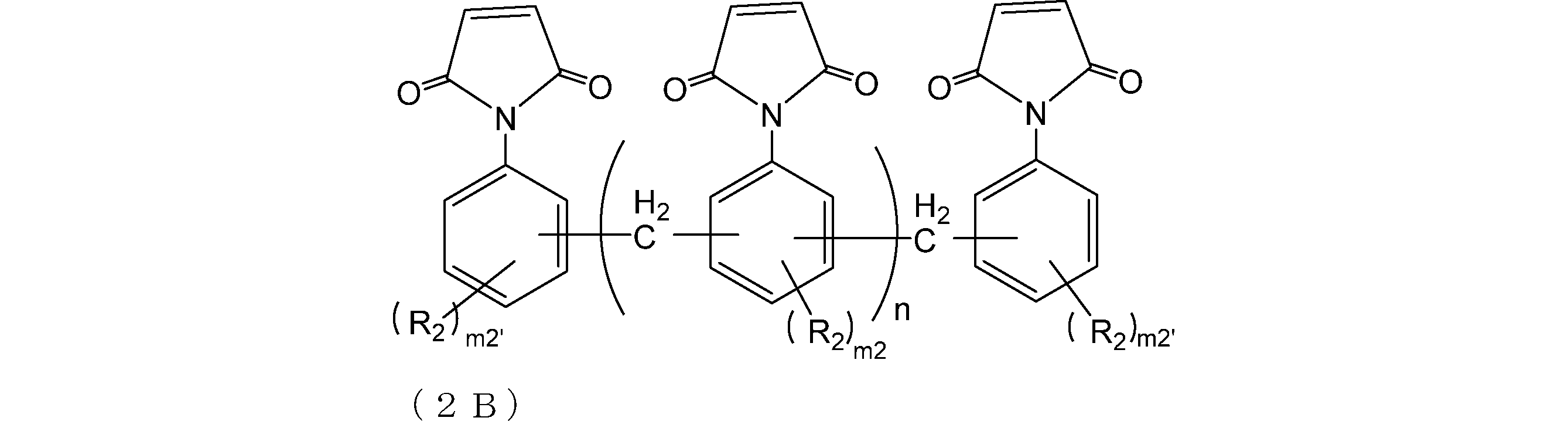
R2は、それぞれ独立して、ヘテロ原子を含んでいてもよい炭素数0~10の基であり、
m2は、それぞれ独立して、0~3の整数であり、
m2’は、それぞれ独立して、0~4の整数であり、
nは、0~4の整数である)。
[15]
式(0B)の基を有する化合物が、式(3B)で表される、[1]~[10]のいずれかに記載のリソグラフィー用膜形成材料

R3及びR4は、それぞれ独立して、ヘテロ原子を含んでいてもよい炭素数0~10の基であり、
m3は、それぞれ独立して、0~4の整数であり、
m4は、それぞれ独立して、0~4の整数であり、
nは、0~4の整数である)。
[16]
架橋剤をさらに含有する、[1]~[15]のいずれかに記載のリソグラフィー用膜形成材料。
[17]
前記架橋剤が、フェノール化合物、エポキシ化合物、シアネート化合物、アミノ化合物、ベンゾオキサジン化合物、メラミン化合物、グアナミン化合物、グリコールウリル化合物、ウレア化合物、イソシアネート化合物及びアジド化合物からなる群より選ばれる少なくとも1種である、[16]に記載のリソグラフィー用膜形成材料。
[18]
前記架橋剤が、少なくとも1つのアリル基を有する、[16]又は[17]に記載のリソグラフィー用膜形成材料。
[19]
前記架橋剤の含有割合が、式(0A)の基を有する化合物と式(0B)の基を有する化合物との合計質量を100質量部とした場合に、0.1~100質量部である、[16]~[18]のいずれかに記載のリソグラフィー用膜形成材料。
[20]
架橋促進剤をさらに含有する、[1]~[19]のいずれかに記載のリソグラフィー用膜形成材料。
[21]
前記架橋促進剤が、アミン類、イミダゾール類、有機ホスフィン類、塩基発生剤、及びルイス酸からなる群より選ばれる少なくとも1種である、[20]に記載のリソグラフィー用膜形成材料。
[22]
前記架橋促進剤の含有割合が、式(0A)の基を有する化合物と式(0B)の基を有する化合物との合計質量を100質量部とした場合に、0.01~5質量部である、[20]又は[21]に記載のリソグラフィー用膜形成材料。
[23]
ラジカル重合開始剤をさらに含有する、[1]~[22]のいずれかに記載のリソグラフィー用膜形成材料。
[24]
前記ラジカル重合開始剤が、ケトン系光重合開始剤、有機過酸化物系重合開始剤及びアゾ系重合開始剤からなる群より選ばれる少なくとも1種である、[23]に記載のリソグラフィー用膜形成材料。
[25]
前記ラジカル重合開始剤の含有割合が、式(0A)の基を有する化合物と式(0B)の基を有する化合物との合計質量を100質量部とした場合に、0.01~25質量部である、[23]又は[24]に記載のリソグラフィー用膜形成材料。
[26]
[1]~[25]のいずれかに記載のリソグラフィー用膜形成材料と溶媒とを含有する、リソグラフィー用膜形成用組成物。
[27]
酸発生剤をさらに含有する、[26]に記載のリソグラフィー用膜形成用組成物。
[28]
リソグラフィー用膜がリソグラフィー用下層膜である、[26]又は[27]に記載のリソグラフィー用膜形成用組成物。
[29]
[28]に記載のリソグラフィー用膜形成用組成物を用いて形成される、リソグラフィー用下層膜。
[30]
基板上に、[28]に記載のリソグラフィー用膜形成用組成物を用いて下層膜を形成する工程、
該下層膜上に、少なくとも1層のフォトレジスト層を形成する工程、及び
該フォトレジスト層の所定の領域に放射線を照射し、現像を行う工程、
を含む、レジストパターン形成方法。
[31]
基板上に、[28]に記載のリソグラフィー用膜形成用組成物を用いて下層膜を形成する工程、
該下層膜上に、珪素原子を含有するレジスト中間層膜材料を用いて中間層膜を形成する工程、
該中間層膜上に、少なくとも1層のフォトレジスト層を形成する工程、
該フォトレジスト層の所定の領域に放射線を照射し、現像してレジストパターンを形成する工程、
該レジストパターンをマスクとして前記中間層膜をエッチングする工程、
得られた中間層膜パターンをエッチングマスクとして前記下層膜をエッチングする工程、及び
得られた下層膜パターンをエッチングマスクとして基板をエッチングすることで基板にパターンを形成する工程、
を含む、回路パターン形成方法。
[32]
[1]~[25]のいずれかに記載のリソグラフィー用膜形成材料を、溶媒に溶解させて有機相を得る工程と、
前記有機相と酸性の水溶液とを接触させて、前記リソグラフィー用膜形成材料中の不純物を抽出する第一抽出工程と、
を含み、
前記有機相を得る工程で用いる溶媒が、水と任意に混和しない溶媒を含む、精製方法。
[33]
前記酸性の水溶液が、鉱酸水溶液又は有機酸水溶液であり、
前記鉱酸水溶液が、塩酸、硫酸、硝酸及びリン酸からなる群より選ばれる1種以上を含み、
前記有機酸水溶液が、酢酸、プロピオン酸、蓚酸、マロン酸、コハク酸、フマル酸、マレイン酸、酒石酸、クエン酸、メタンスルホン酸、フェノールスルホン酸、p-トルエンスルホン酸及びトリフルオロ酢酸からなる群より選ばれる1種以上を含む、[32]に記載の精製方法。
[34]
前記水と任意に混和しない溶媒が、トルエン、キシレン、2-ヘプタノン、シクロヘキサノン、シクロペンタノン、シクロペンチルメチルエーテル、メチルテトラヒドロフラン、ブタノール、ヘキサノール、メチルイソブチルケトン、プロピレングリコールモノメチルエーテルアセテート、酢酸ブチル、酢酸イソブチル、酢酸イソアミル及び酢酸エチルからなる群より選ばれる1種以上の溶媒である、[32]又は[33]に記載の精製方法。
[35]
前記第一抽出工程後、前記有機相を、水に接触させて、前記リソグラフィー用膜形成材料中の不純物を抽出する第二抽出工程をさらに含む、[32]~[34]のいずれかに記載の精製方法。
<化合物>
本発明の一実施形態は、式(0A)の基:

RAは、水素原子又は炭素数1~4のアルキル基であり、
RBは、炭素数1~4のアルキル基である)
を有する化合物;及び
式(0B)の基:

を含む、リソグラフィー用膜形成材料に関する。

RA及びRBは前記のとおりであり、
Zはヘテロ原子を含んでいてもよい炭素数1~100の2価の炭化水素基である。)
炭化水素基の炭素数は、1~80、1~60、1~40、1~20等であってもよい。ヘテロ原子としては、酸素、窒素、硫黄、フッ素、ケイ素等を挙げることができる。

RA及びRBは前記のとおりであり、
Xは、それぞれ独立して、単結合、-O-、-CH2-、-C(CH3)2-、-CO-、-C(CF3)2-、-CONH-又は-COO-であり、
Aは、単結合、酸素原子、又はヘテロ原子(例えば、酸素、窒素、硫黄、フッ素)を含んでいてもよい炭素数1~80の2価の炭化水素基であり、
R1は、それぞれ独立して、ヘテロ原子(例えば、酸素、窒素、硫黄、フッ素、塩素、臭素、ヨウ素)を含んでいてもよい炭素数0~30の基であり、
m1は、それぞれ独立して、0~4の整数である。)


pは0~20の整数であることが好ましく、
qは0~4の整数であることが好ましい。
Yは、耐熱性向上の観点から、単結合であることが好ましい。
R1は、ヘテロ原子(例えば、酸素、窒素、硫黄、フッ素、塩素、臭素、ヨウ素)を含んでいてもよい炭素数0~20又は0~10の基であることが好ましい。R1は、有機溶媒への溶解性向上の観点から、炭化水素基であることが好ましい。例えば、R1として、アルキル基(例えば、炭素数1~6又は1~3のアルキル基)等が挙げられ、具体的にはメチル基、エチル基等が挙げられる。
m1は、0~2の整数であることが好ましく、原料入手性及び溶解性向上の観点から、1又は2であることがより好ましい。
qは、2~4の整数であることが好ましい。
pは、0~2の整数であることが好ましく、耐熱性向上の観点から、1~2の整数であることがより好ましい。
低温での硬化性とエッチング耐性向上の観点から、化合物0A及び化合物0Bは、それぞれ、式(2A)及び式(2B)で表される化合物であることが好ましい。

RA及びRBは前記のとおりであり、
R2は、それぞれ独立して、ヘテロ原子を含んでいてもよい炭素数0~10の基であり、
m2は、それぞれ独立して、0~3の整数であり、
m2’は、それぞれ独立して、0~4の整数であり、
nは、0~4の整数である)
m2はそれぞれ独立に0~3の整数である。また、m2は、0又は1であることが好ましく、原料入手性の観点から、0であることがより好ましい。
m2’はそれぞれ独立に、0~4の整数である。また、m2’は、0又は1であることが好ましく、原料入手性の観点から、0であることがより好ましい。
nは、0~4の整数である。また、nは、1~4又は0~2の整数であることが好ましく、耐熱性向上の観点から、1~2の整数であることがより好ましい。

RA及びRBは前記のとおりであり、
R3及びR4は、それぞれ独立して、ヘテロ原子を含んでいてもよい炭素数0~10の基であり、
m3は、それぞれ独立して、0~4の整数であり、
m4は、それぞれ独立して、0~4の整数であり、
nは、0~4の整数である)
m3はそれぞれ独立に0~4の整数である。また、m3は、0~2の整数であることが好ましく、原料入手性の観点から、0であることがより好ましい。
m4はそれぞれ独立に、0~4の整数である。また、m4は、0~2の整数であることが好ましく、原料入手性の観点から、0であることがより好ましい。
nは、0~4の整数である。また、nは、1~4又は0~2の整数であることが好ましく、原料入手性の観点から、1~2の整数であることがより好ましい。
上記ビスシトラコンイミド化合物の中でも特にビス(3-エチル-5-メチル-4-シトラコンイミドフェニル)メタン、N,N'-4,4'-[3,3'-ジメチル-ジフェニルメタン]ビスシトラコンイミド、N,N'-4,4'-[3,3'-ジエチルジフェニルメタン]ビスシトラコンイミドが、溶剤溶解性に優れるため、好ましい。
本実施形態のリソグラフィー用膜形成材料は、化合物0A及び化合物0Bに加え、硬化温度の低下やインターミキシングを抑制する等の観点から、必要に応じて架橋剤を含有していてもよい。

本実施形態のリソグラフィー用膜形成材料には、必要に応じてラジカル重合開始剤を配合することができる。ラジカル重合開始剤としては、光によりラジカル重合を開始させる光重合開始剤であってもよいし、熱によりラジカル重合を開始させる熱重合開始剤であってもよい。
前記リソグラフィー用膜形成材料は酸性水溶液で洗浄して精製することが可能である。前記精製方法は、リソグラフィー用膜形成材料を水と任意に混和しない有機溶媒に溶解させて有機相を得て、その有機相を酸性水溶液と接触させ抽出処理(第一抽出工程)を行うことにより、リソグラフィー用膜形成材料と有機溶媒とを含む有機相に含まれる金属分を水相に移行させたのち、有機相と水相とを分離する工程を含む。該精製により本発明のリソグラフィー用膜形成材料の種々の金属の含有量を著しく低減させることができる。
本実施形態のリソグラフィー用膜形成用組成物は、前記リソグラフィー用膜形成材料と溶媒とを含有する。リソグラフィー用膜は、例えば、リソグラフィー用下層膜である。
本実施形態のリソグラフィー用膜形成用組成物に用いる溶媒としては、化合物0A及び化合物0Bが少なくとも溶解するものであれば、特に限定されず、公知のものを適宜用いることができる。
本実施形態のリソグラフィー用膜形成用組成物は、架橋反応をさらに促進させる等の観点から、必要に応じて酸発生剤を含有していてもよい。酸発生剤としては、熱分解によって酸を発生するもの、光照射によって酸を発生するもの等が知られているが、いずれのものも使用することができる。
さらに、本実施形態のリソグラフィー用下層膜形成用組成物は、保存安定性を向上させる等の観点から、塩基性化合物を含有していてもよい。
本実施形態のリソグラフィー用下層膜は、本実施形態のリソグラフィー用膜形成用組成物を用いて形成される。
合成した化合物の分子量は、Water社製Acquity UPLC/MALDI-Synapt HDMSを用いて、LC-MS分析により測定した。
エスアイアイ・ナノテクノロジー社製EXSTAR6000TG-DTA装置を使用し、試料約5mgをアルミニウム製非密封容器に入れ、窒素ガス(100ml/min)気流中昇温速度10℃/minで500℃まで昇温することにより熱重量減少量を測定した。実用的観点からは、下記A又はB評価が好ましい。A又はB評価であれば、高い耐熱性を有し、高温ベークへの適用が可能である。
<評価基準>
A:400℃での熱重量減少量が、10%未満
B:400℃での熱重量減少量が、10%~25%
C:400℃での熱重量減少量が、25%超
50mlのスクリュー瓶にプロピレングリコールモノメチルエーテルアセテート(PGMEA)と化合物及び/又は樹脂を仕込み、23℃にてマグネチックスターラーで1時間撹拌後に、化合物及び/又は樹脂のPGMEAに対する溶解量を測定し、その結果を以下の基準で評価した。実用的観点からは、下記S、A又はB評価が好ましい。S、A又はB評価であれば、溶液状態で高い保存安定性を有し、半導体微細加工プロセスで広く用いられるエッジビートリンス液(PGME/PGMEA混合液)にも十分に適用が可能である。
<評価基準>
S:20質量%以上30質量%未満
A:10質量%以上20質量%未満
B:5質量%以上10質量%未満
C:5質量%未満
攪拌機、冷却管及びビュレットを備えた内容積100mlの容器を準備した。この容器に、2,2-ビス[4-(4-アミノフェノキシ)フェニル]プロパン(製品名:BAPP、和歌山精化工業(株)製)4.10g(10.0mmol)、無水シトラコン酸(関東化学(株)製)4.15g(40.0mmol)、ジメチルフォルムアミド30mlおよびトルエン60mlを仕込み、p-トルエンスルホン酸0.4g(2.3mmol)、重合禁止剤BHT0.1gを加えて、反応液を調製した。この反応液を120℃で5時間撹拌して反応を行い、共沸脱水にて生成水をディーンスタークトラップにて回収した。次に、反応液を40℃に冷却した後、蒸留水300mlを入れたビーカーに滴下し、生成物を析出させた。得られたスラリー溶液をろ過後、残渣をアセトンで洗浄し、カラムクロマトによる分離精製を行うことにより、下記式で示される目的化合物(BAPPシトラコンイミド)3.76gを得た。

1H-NMR:(d-DMSO、内部標準TMS)
δ(ppm)6.8~7.4(16H,Ph-H)、6.7(2H,-CH=C)、2.1(6H,C-CH3)、1.6(6H,-C(CH3)2)。得られた化合物について、前記方法により分子量を測定した結果、598であった。
攪拌機、冷却管及びビュレットを備えた内容積100mlの容器を準備した。この容器に、3,3’-(1,3-フェニレンビス)オキシジアニリン(製品名:APB-N、三井化学ファイン(株)製)2.92g(10.0mmol)、無水シトラコン酸(関東化学(株)製)4.15g(40.0mmol)、ジメチルフォルムアミド30mlおよびトルエン60mlを仕込み、p-トルエンスルホン酸0.4g(2.3mmol)、重合禁止剤BHT0.1gを加えて、反応液を調製した。この反応液を110℃で5時間撹拌して反応を行い、共沸脱水にて生成水をディーンスタークトラップにて回収した。次に、反応液を40℃に冷却した後、蒸留水300mlを入れたビーカーに滴下し、生成物を析出させた。得られたスラリー溶液をろ過後、残渣をメタノールで洗浄し、カラムクロマトによる分離精製を行うことにより、下記式で示される目的化合物(APB-Nシトラコンイミド)3.52gを得た。

1H-NMR:(d-DMSO、内部標準TMS)
δ(ppm)6.7~7.4(12H,Ph-H)、6.4(2H,-CH=C)、2.2(6H,C-CH3)。得られた化合物について、前記方法により分子量を測定した結果、480であった。
攪拌機、冷却管及びビュレットを備えた内容積100mlの容器を準備した。この容器に、3,3’-(1,3-フェニレンビス)オキシジアニリン(製品名:APB-N、三井化学ファイン(株)製)2.92g(10.0mmol)、無水マレイン酸(関東化学(株)製)2.15g(22.0mmol)、ジメチルフォルムアミド30mlおよびm-キシレン30mlを仕込み、p-トルエンスルホン酸0.4g(2.3mmol)を加えて、反応液を調製した。この反応液を130℃で4.0時間撹拌して反応を行い、共沸脱水にて生成水をディーンスタークトラップにて回収した。次に、反応液を40℃に冷却した後、蒸留水300mlを入れたビーカーに滴下し、生成物を析出させた。得られたスラリー溶液をろ過後、残渣をメタノールで洗浄し、カラムクロマトによる分離精製を行うことにより、下記式で示される目的化合物(APB-Nマレイミド)1.84gを得た。

1H-NMR:(d-DMSO、内部標準TMS)
δ(ppm)6.8~7.5(12H,Ph-H)、7.1(4H,-CH=CH-)。得られた化合物について、前記方法により分子量を測定した結果、452であった。
攪拌機、冷却管及びビュレットを備えた内容積100mlの容器を準備した。この容器に、2,2-ビス[4-(4-アミノフェノキシ)フェニル]ヘキサフルオロプロパン(製品名:HFBAPP、和歌山精化工業(株)製)5.18g(10.0mmol)、無水シトラコン酸(関東化学(株)製)4.56g(44.0mmol)、ジメチルフォルムアミド30mlおよびトルエン60mlを仕込み、p-トルエンスルホン酸0.4g(2.3mmol)、重合禁止剤BHT0.1gを加えて、反応液を調製した。この反応液を110℃で5.0時間撹拌して反応を行い、共沸脱水にて生成水をディーンスタークトラップにて回収した。次に、反応液を40℃に冷却した後、蒸留水300mlを入れたビーカーに滴下し、生成物を析出させた。得られたスラリー溶液をろ過後、残渣をメタノールで洗浄し、カラムクロマトによる分離精製を行うことにより、下記式で示される目的化合物(HFBAPPシトラコンイミド)3.9gを得た。

1H-NMR:(d-DMSO、内部標準TMS)
δ(ppm)6.6~7.3(16H,Ph-H)、6.4(2H,-CH=C)、2.2(6H,C-CH3)。
得られた化合物について、前記方法により分子量を測定した結果、706であった。
攪拌機、冷却管及びビュレットを備えた内容積100mlの容器を準備した。この容器に、2,2-ビス[4-(4-アミノフェノキシ)フェニル]ヘキサフルオロプロパン(製品名:HFBAPP、和歌山精化工業(株)製)5.18g(10.0mmol)、無水マレイン酸(関東化学(株)製)2.15g(22.0mmol)、ジメチルフォルムアミド30mlおよびm-キシレン30mlを仕込み、p-トルエンスルホン酸0.4g(2.3mmol)を加えて、反応液を調製した。この反応液を130℃で5.0時間撹拌して反応を行い、共沸脱水にて生成水をディーンスタークトラップにて回収した。次に、反応液を40℃に冷却した後、蒸留水300mlを入れたビーカーに滴下し、生成物を析出させた。得られたスラリー溶液をろ過後、残渣をメタノールで洗浄し、カラムクロマトによる分離精製を行うことにより、下記式で示される目的化合物(HFBAPPマレイミド)3.5gを得た。

1H-NMR:(d-DMSO、内部標準TMS)
δ(ppm)6.6~7.4(16H,Ph-H)、6.4(4H,-CH=CH-)
得られた化合物について、前記方法により分子量を測定した結果、678であった。
攪拌機、冷却管及びビュレットを備えた内容積100mlの容器を準備した。この容器に、1,4-ビス[2-(4-アミノフェニル)-2-プロピル]ベンゼン(製品名:ビスアニリンP、三井化学ファイン(株)製)5.18g(10.0mmol)、無水シトラコン酸(関東化学(株)製)4.56g(44.0mmol)、ジメチルフォルムアミド30mlおよびトルエン60mlを仕込み、p-トルエンスルホン酸0.4g(2.3mmol)、重合禁止剤BHT0.1gを加えて、反応液を調製した。この反応液を110℃で6.0時間撹拌して反応を行い、共沸脱水にて生成水をディーンスタークトラップにて回収した。次に、反応液を40℃に冷却した後、蒸留水300mlを入れたビーカーに滴下し、生成物を析出させた。得られたスラリー溶液をろ過後、残渣をメタノールで洗浄し、カラムクロマトによる分離精製を行うことにより、下記式で示される目的化合物(BisAPシトラコンイミド)4.2gを得た。

1H-NMR:(d-DMSO、内部標準TMS)
δ(ppm)6.8~7.4(12H,Ph-H)、6.7(2H,-CH=C)、2.1(6H,C-CH3)、1.6~1.7(12H,-C(CH3)2)。得られた化合物について、前記方法により分子量を測定した結果、532であった。
攪拌機、冷却管及びビュレットを備えた内容積100mlの容器を準備した。この容器に、1,4-ビス[2-(4-アミノフェニル)-2-プロピル]ベンゼン(製品名:ビスアニリンP、三井化学ファイン(株)製)4.61g(10.0mmol)、無水マレイン酸(関東化学(株)製)2.15g(22.0mmol)、ジメチルフォルムアミド40mlおよびm-キシレン30mlを仕込み、p-トルエンスルホン酸0.4g(2.3mmol)を加えて、反応液を調製した。この反応液を130℃で4.0時間撹拌して反応を行い、共沸脱水にて生成水をディーンスタークトラップにて回収した。次に、反応液を40℃に冷却した後、蒸留水300mlを入れたビーカーに滴下し、生成物を析出させた。得られたスラリー溶液をろ過後、残渣をメタノールで洗浄し、カラムクロマトによる分離精製を行うことにより、下記式で示される目的化合物(BisAPマレイミド)2.4gを得た。

1H-NMR:(d-DMSO、内部標準TMS)
δ(ppm)6.7~7.4(12H,Ph-H)、6.4(4H,-CH=CH-)、1.6~1.7(12H,-C(CH3)2)。
得られた化合物について、前記方法により分子量を測定した結果、504であった。
攪拌機、冷却管及びビュレットを備えた内容積100mlの容器を準備した。この容器に、特開2001-26571号公報の合成例1を追試することで得られたジアミノジフェニルメタンオリゴマー2.4g、無水シトラコン酸(関東化学(株)製)4.56g(44.0mmol)、ジメチルフォルムアミド40mlおよびトルエン60mlを仕込み、p-トルエンスルホン酸0.4g(2.3mmol)および重合禁止剤BHT0.1gを加えて、反応液を調製した。この反応液を110℃で8.0時間撹拌して反応を行い、共沸脱水にて生成水をディーンスタークトラップにて回収した。次に、反応液を40℃に冷却した後、蒸留水300mlを入れたビーカーに滴下し、生成物を析出させた。得られたスラリー溶液をろ過後、残渣をメタノールで洗浄し、下記式で示されるシトラコンイミド樹脂(BMIシトラコンイミド樹脂)4.7gを得た。

攪拌機、冷却管及びビュレットを備えた内容積100mlの容器を準備した。この容器に、ビフェニルアラルキル型ポリアニリン樹脂(製品名:BAN、日本化薬(株)製)6.30g、無水シトラコン酸(関東化学(株)製)4.56g(44.0mmol)、ジメチルフォルムアミド40mlおよびトルエン60mlを仕込み、p-トルエンスルホン酸0.4g(2.3mmol)、重合禁止剤BHT0.1gを加えて、反応液を調製した。この反応液を110℃で6.0時間撹拌して反応を行い、共沸脱水にて生成水をディーンスタークトラップにて回収した。次に、反応液を40℃に冷却した後、蒸留水300mlを入れたビーカーに滴下し、生成物を析出させた。得られたスラリー溶液をろ過後、残渣をメタノールで洗浄し、カラムクロマトによる分離精製を行うことにより、下記式で示される目的化合物(BANシトラコンイミド樹脂)5.5gを得た。

ビスシトラコンイミド化合物として、合成実施例1で得られたBAPPシトラコンイミド5質量部、およびビスマレイミド化合物として、下記式で表されるビスマレイミド(BMI-80;ケイアイ化成製)5質量部をそれぞれ用いて、リソグラフィー用膜形成材料とした。
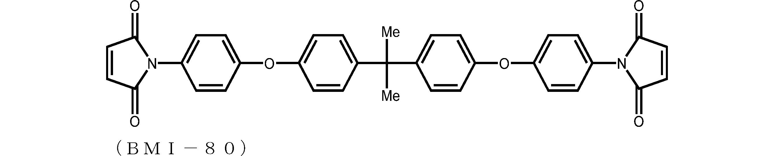
前記リソグラフィー用膜形成材料10質量部に対し、溶媒としてPGMEAを90質量部加え、室温下、スターラーで少なくとも3時間以上攪拌させることにより、リソグラフィー用膜形成用組成物を調製した。
BAPPシトラコンイミド及びBMI-80の量を、表1に示すように、それぞれ変更した以外は、実施例1と同様の操作にてリソグラフィー用膜形成用組成物を調製した。
ビスシトラコンイミド化合物として、合成実施例2-1で得られたAPB-Nシトラコンイミド5質量部、およびビスマレイミド化合物として、合成実施例2-2で得られたAPB-Nマレイミド5質量部をそれぞれ用いて、リソグラフィー用膜形成材料とした。
熱重量測定の結果、得られたリソグラフィー用膜形成材料の400℃での熱重量減少量は10%未満(評価A)であった。また、PGMEAへの溶解性を評価した結果、10質量%以上20質量%未満(評価A)であり、得られたリソグラフィー用膜形成材料は十分な溶解性を有するものと評価された。
前記実施例1と同様の操作にてリソグラフィー用膜形成用組成物を調製した。
ビスシトラコンイミド化合物として、合成実施例3-1で得られたHFBAPPシトラコンイミド5質量部、およびビスマレイミド化合物として、合成実施例3-2で得られたHFBAPPビスマレイミド5質量部をそれぞれ用いて、リソグラフィー用膜形成材料とした。
熱重量測定の結果、得られたリソグラフィー用膜形成材料の400℃での熱重量減少量は10%未満(評価A)であった。また、PGMEAへの溶解性を評価した結果、20質量%以上(評価S)であり、得られたリソグラフィー用膜形成材料は十分な溶解性を有するものと評価された。
前記実施例1と同様の操作にてリソグラフィー用膜形成用組成物を調製した。
ビスシトラコンイミド化合物として、合成実施例4-1で得られたBisAPシトラコンイミド5質量部、およびビスマレイミド化合物として、合成実施例4-2で得られたBisAPビスマレイミド5質量部をそれぞれ用いて、リソグラフィー用膜形成材料とした。
熱重量測定の結果、得られたリソグラフィー用膜形成材料の400℃での熱重量減少量は10%未満(評価A)であった。また、PGMEAへの溶解性を評価した結果、20質量%以上(評価S)であり、得られたリソグラフィー用膜形成材料は十分な溶解性を有するものと評価された。
前記実施例1と同様の操作にてリソグラフィー用膜形成用組成物を調製した。
シトラコンイミド樹脂として、合成実施例5で得られたBMIシトラコンイミド樹脂を5質量部、およびビスマレイミド樹脂として、下記式で表されるBMIマレイミドオリゴマー(BMI-2300、大和化成工業製)5質量部をそれぞれ用いて、リソグラフィー用膜形成材料とした。
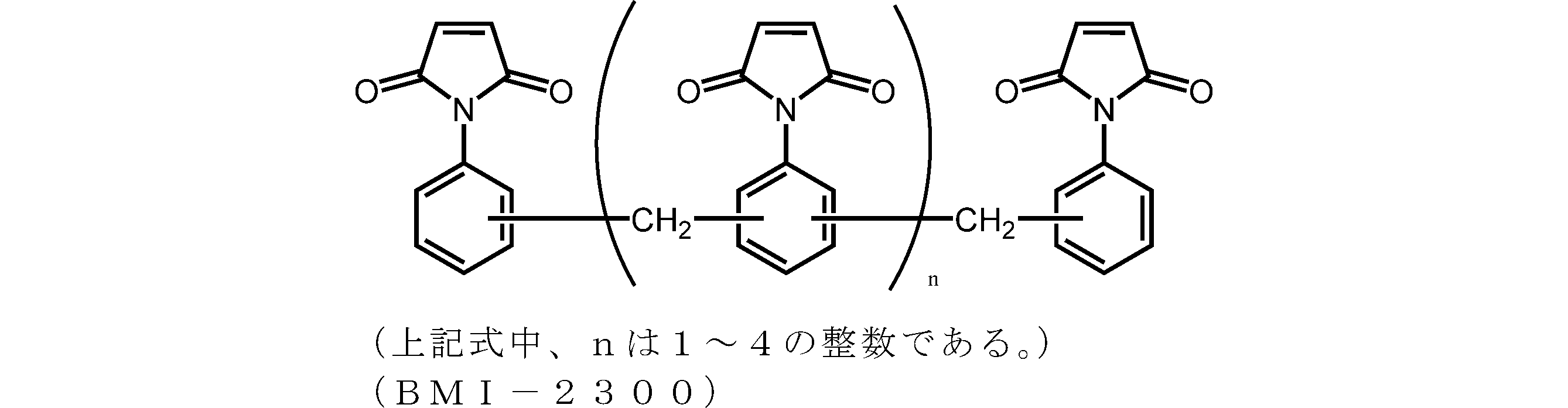
前記実施例1と同様の操作にてリソグラフィー用膜形成用組成物を調製した。
BMIシトラコンイミド樹脂及びBMI-2300の量を、表1に示すように、それぞれ変更した以外は、実施例1と同様の操作にてリソグラフィー用膜形成用組成物を調製した。
シトラコンイミド樹脂として、合成実施例6で得られたBANシトラコンイミド樹脂5質量部、およびビスマレイミド樹脂として、下記式で表されるビフェニルアラルキル型マレイミド樹脂(MIR-3000-L、日本化薬株式会社製)5質量部をそれぞれ用いて、リソグラフィー用膜形成材料とした。

前記実施例1と同様の操作にてリソグラフィー用膜形成用組成物を調製した。
ビスシトラコンイミド化合物として、BAPPシトラコンイミドを5質量部、およびビスマレイミド化合物として、BMI-80を5質量部、また、架橋促進剤として2,4,5-トリフェニルイミダゾール(TPIZ)を0.1質量部配合し、リソグラフィー用膜形成材料とした。
熱重量測定の結果、得られたリソグラフィー用膜形成材料の400℃での熱重量減少量は10%未満(評価A)であった。また、PGMEAへの溶解性を評価した結果、20質量%以上(評価S)であり、得られたリソグラフィー用膜形成材料は良好な溶解性を有するものと評価された。
前記実施例1と同様の操作にてリソグラフィー用膜形成用組成物を調製した。
ビスシトラコンイミド化合物として、合成実施例2-1で得られたAPB-Nシトラコンイミドを5質量部、ビスマレイミド化合物として、合成実施例2-2で得られたAPB-Nマレイミドを5質量部使用した。また、架橋促進剤としてTPIZを0.1質量部配合し、リソグラフィー用膜形成材料とした。
熱重量測定の結果、得られたリソグラフィー用膜形成材料の400℃での熱重量減少量は10%未満(評価A)であった。また、PGMEAへの溶解性を評価した結果、20質量%以上(評価S)であり、得られたリソグラフィー用膜形成材料は優れた溶解性を有するものと評価された。
前記実施例1と同様の操作にてリソグラフィー用膜形成用組成物を調製した。
ビスシトラコンイミド化合物として、合成実施例3-1で得られたHFBAPPシトラコンイミドを5質量部、ビスマレイミド化合物として、合成実施例3-2で得られたHFBAPPマレイミドを5質量部使用した。また、架橋促進剤としてTPIZを0.1質量部配合し、リソグラフィー用膜形成材料とした。
熱重量測定の結果、得られたリソグラフィー用膜形成材料の400℃での熱重量減少量は10%未満(評価A)であった。また、PGMEAへの溶解性を評価した結果、20質量%以上(評価S)であり、得られたリソグラフィー用膜形成材料は優れた溶解性を有するものと評価された。
前記実施例1と同様の操作にてリソグラフィー用膜形成用組成物を調製した。
ビスシトラコンイミド化合物として、合成実施例4-1で得られたBisAPシトラコンイミドを5質量部、ビスマレイミド化合物として、合成例4-2で得られたBisAPマレイミドを5質量部使用した。また、架橋促進剤としてTPIZを0.1質量部配合し、リソグラフィー用膜形成材料とした。
熱重量測定の結果、得られたリソグラフィー用膜形成材料の400℃での熱重量減少量は10%未満(評価A)であった。また、PGMEAへの溶解性を評価した結果、20質量%以上(評価S)であり、得られたリソグラフィー用膜形成材料は優れた溶解性を有するものと評価された。
前記実施例1と同様の操作にてリソグラフィー用膜形成用組成物を調製した。
シトラコンイミド樹脂として、合成実施例5で得られたBMIシトラコンイミド樹脂を5質量部、マレイミド樹脂として、大和化成工業製のBMI-2300を5質量部使用した。また、架橋促進剤としてTPIZを0.1質量部配合し、リソグラフィー用膜形成材料とした。
熱重量測定の結果、得られたリソグラフィー用膜形成材料の400℃での熱重量減少量は10%未満(評価A)であった。また、PGMEAへの溶解性を評価した結果、20質量%以上(評価S)であり、得られたリソグラフィー用膜形成材料は優れた溶解性を有するものと評価された。
前記実施例1と同様の操作にてリソグラフィー用膜形成用組成物を調製した。
シトラコンイミド樹脂として、合成実施例6で得られたBANシトラコンイミド樹脂を5質量部、マレイミド樹脂として、日本化薬製のMIR-3000-Lを5質量部使用した。また、架橋促進剤としてTPIZを0.1質量部配合し、リソグラフィー用膜形成材料とした。
熱重量測定の結果、得られたリソグラフィー用膜形成材料の400℃での熱重量減少量は10%未満(評価A)であった。また、PGMEAへの溶解性を評価した結果、20質量%以上(評価S)であり、得られたリソグラフィー用膜形成材料は優れた溶解性を有するものと評価された。
前記実施例1と同様の操作にてリソグラフィー用膜形成用組成物を調製した。
ビスシトラコンイミド化合物として、BAPPシトラコンイミドを5質量部、およびビスマレイミド化合物として、BMI-80を5質量部使用した。また、架橋剤として、下記式で表されるベンゾオキサジン(BF-BXZ;小西化学工業株式会社製)2質量部を使用し、架橋促進剤として2,4,5-トリフェニルイミダゾール(TPIZ)を0.1質量部配合し、リソグラフィー用膜形成材料とした。

前記実施例1と同様の操作にてリソグラフィー用膜形成用組成物を調製した。
ビスシトラコンイミド化合物として、BAPPシトラコンイミドを5質量部、およびビスマレイミド化合物として、BMI-80を5質量部使用した。また、架橋剤として、下記式で表されるビフェニルアラルキル型エポキシ樹脂(NC-3000-L;日本化薬株式会社製)2質量部を使用し、架橋促進剤としてTPIZを0.1質量部配合し、リソグラフィー用膜形成材料とした。
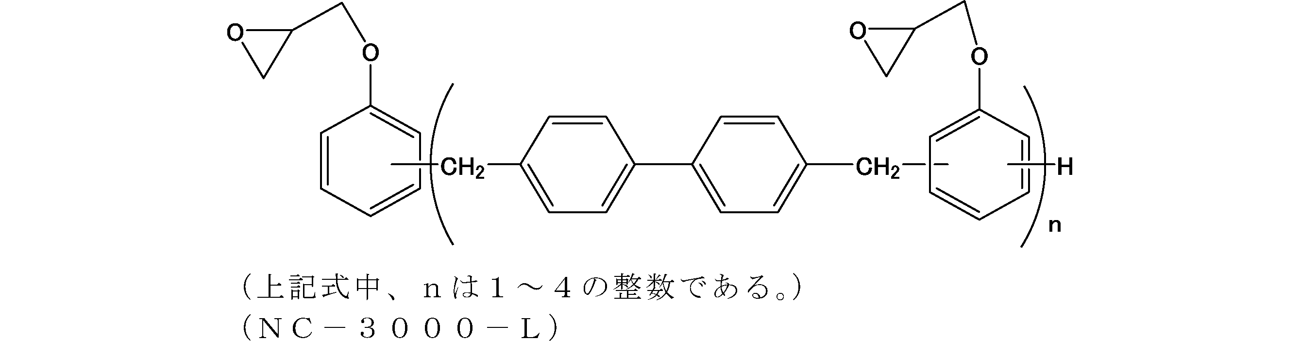
前記実施例1と同様の操作にてリソグラフィー用膜形成用組成物を調製した。
ビスシトラコンイミド化合物として、BAPPシトラコンイミドを5質量部、およびビスマレイミド化合物として、BMI-80を5質量部使用した。また、架橋剤として、下記式で表されるジアリルビスフェノールA型シアネート(DABPA-CN;三菱ガス化学製)2質量部を使用し、架橋促進剤として2,4,5-トリフェニルイミダゾール(TPIZ)を0.1質量部配合し、リソグラフィー用膜形成材料とした。

前記実施例1と同様の操作にてリソグラフィー用膜形成用組成物を調製した。
ビスシトラコンイミド化合物として、BAPPシトラコンイミドを5質量部、およびビスマレイミド化合物として、BMI-80を5質量部使用した。また、架橋剤として、下記式で表されるジアリルビスフェノールA(BPA-CA;小西化学製)2質量部を使用し、架橋促進剤として2,4,5-トリフェニルイミダゾール(TPIZ)を0.1質量部配合し、リソグラフィー用膜形成材料とした。

前記実施例1と同様の操作にてリソグラフィー用膜形成用組成物を調製した。
ビスシトラコンイミド化合物として、BAPPシトラコンイミドを5質量部、およびビスマレイミド化合物として、BMI-80を5質量部使用した。また、架橋剤として、下記式で表されるジフェニルメタン型アリルフェノール樹脂(APG-1;群栄化学工業製)2質量部を使用し、リソグラフィー用膜形成材料とした。

前記実施例1と同様の操作にてリソグラフィー用膜形成用組成物を調製した。
ビスシトラコンイミド化合物として、BAPPシトラコンイミドを5質量部、およびビスマレイミド化合物として、BMI-80を5質量部使用した。また、架橋剤として、下記式で表されるジフェニルメタン型プロペニルフェノール樹脂(APG-2;群栄化学工業製)2質量部を使用し、リソグラフィー用膜形成材料とした。

前記実施例1と同様の操作にてリソグラフィー用膜形成用組成物を調製した。
ビスシトラコンイミド化合物として、BAPPシトラコンイミドを5質量部、およびビスマレイミド化合物として、BMI-80を5質量部使用した。また、架橋剤として、下記式で表される4,4´-ジアミノジフェニルメタン(DDM;東京化成製)2質量部を使用し、リソグラフィー用膜形成材料とした。

前記実施例1と同様の操作にてリソグラフィー用膜形成用組成物を調製した。
ビスシトラコンイミド化合物として、BAPPシトラコンイミドを5質量部、およびビスマレイミド化合物として、BMI-80を5質量部使用した。また、光重合開始剤として下記式で表されるイルガキュア184(BASF社製)を0.1質量部配合し、リソグラフィー用膜形成材料とした。
前記ビスマレイミド化合物10質量部に対し、溶媒としてPGMEAを90質量部加え、室温下、スターラーで少なくとも3時間以上攪拌させることにより、リソグラフィー用膜形成用組成物を調製した。

ビスシトラコンイミド化合物として、合成実施例2-1で得られたAPB-Nシトラコンイミドを5質量部、ビスマレイミド化合物として、合成実施例2-2で得られたAPB-Nマレイミドを5質量部使用した。また、光重合開始剤としてイルガキュア184(BASF社製)を0.1質量部配合し、リソグラフィー用膜形成材料とした。
前記実施例20と同様の操作にてリソグラフィー用膜形成用組成物を調製した。
ビスシトラコンイミド化合物として、合成実施例3-1で得られたHFBAPPシトラコンイミドを5質量部、ビスマレイミド化合物として、合成実施例3-2で得られたHFBAPPマレイミドを5質量部使用した。また、光重合開始剤としてイルガキュア184(BASF社製)を0.1質量部配合し、リソグラフィー用膜形成材料とした。
前記実施例20と同様の操作にてリソグラフィー用膜形成用組成物を調製した。
ビスシトラコンイミド化合物として、合成実施例4-1で得られたBisAPシトラコンイミドを5質量部、ビスマレイミド化合物として、合成実施例4-2で得られたBisAPマレイミドを5質量部使用した。また、光重合開始剤としてイルガキュア184(BASF社製)を0.1質量部配合し、リソグラフィー用膜形成材料とした。
前記実施例20と同様の操作にてリソグラフィー用膜形成用組成物を調製した。
シトラコンイミド樹脂として、合成実施例5で得られたBMIシトラコンイミド樹脂を5質量部、マレイミド樹脂として、大和化成工業製のBMI-2300を5質量部使用した。また、光重合開始剤としてイルガキュア184(BASF社製)を0.1質量部配合し、リソグラフィー用膜形成材料とした。
前記実施例20と同様の操作にてリソグラフィー用膜形成用組成物を調製した。
シトラコンイミド樹脂として、合成実施例6で得られたBANシトラコンイミド樹脂を5質量部、マレイミド樹脂として、日本化薬製のMIR-3000-Lを5質量部使用した。また、光重合開始剤としてイルガキュア184(BASF社製)を0.1質量部配合し、リソグラフィー用膜形成材料とした。
前記実施例20と同様の操作にてリソグラフィー用膜形成用組成物を調製した。
ビスシトラコンイミド化合物として、BAPPシトラコンイミドを5質量部、およびビスマレイミド化合物として、BMI-80を5質量部使用した。また、架橋剤として、BF-BXZを2質量部使用し、光ラジカル重合開始剤として、イルガキュア184(BASF社製)0.1質量部配合し、リソグラフィー用膜形成材料とした。
前記実施例20と同様の操作にてリソグラフィー用膜形成用組成物を調製した。
ビスシトラコンイミド化合物として、BAPPシトラコンイミドを5質量部、およびビスマレイミド化合物として、BMI-80を5質量部使用した。また、架橋剤として、NC-3000-Lを2質量部使用し、光ラジカル重合開始剤として、イルガキュア184(BASF社製)を0.1質量部配合し、リソグラフィー用膜形成材料とした。
前記実施例20と同様の操作にてリソグラフィー用膜形成用組成物を調製した。
ビスシトラコンイミド化合物として、BAPPシトラコンイミドを5質量部、およびビスマレイミド化合物として、BMI-80を5質量部使用した。また、架橋剤として、DABPA-CNを2質量部使用し、光ラジカル重合開始剤として、イルガキュア184(BASF社製)を0.1質量部配合し、リソグラフィー用膜形成用材料とした。
前記実施例20と同様の操作にてリソグラフィー用膜形成用組成物を調製した。
ビスシトラコンイミド化合物として、BAPPシトラコンイミドを5質量部、およびビスマレイミド化合物として、BMI-80を5質量部使用した。また、架橋剤として、BPA-CAを2質量部使用し、光ラジカル重合開始剤として、イルガキュア184(BASF社製)を0.1質量部配合し、リソグラフィー用膜形成材料とした。
前記実施例20と同様の操作にてリソグラフィー用膜形成用組成物を調製した。
ビスシトラコンイミド化合物として、BAPPシトラコンイミドを5質量部、およびビスマレイミド化合物として、BMI-80を5質量部使用した。また、架橋剤として、APG-1を2質量部使用し、光ラジカル重合開始剤として、イルガキュア184(BASF社製)を0.1質量部配合し、リソグラフィー用膜形成材料とした。
前記実施例20と同様の操作にてリソグラフィー用膜形成用組成物を調製した。
ビスシトラコンイミド化合物として、BAPPシトラコンイミドを5質量部、およびビスマレイミド化合物として、BMI-80を5質量部使用した。また、架橋剤として、APG-2を2質量部使用し、光ラジカル重合開始剤として、イルガキュア184(BASF社製)を0.1質量部配合し、リソグラフィー用膜形成材料とした。
前記実施例20と同様の操作にてリソグラフィー用膜形成用組成物を調製した。
ビスシトラコンイミド化合物として、BAPPシトラコンイミドを5質量部、およびビスマレイミド化合物として、BMI-80を5質量部使用した。また、架橋剤として、DDMを2質量部使用し、光ラジカル重合開始剤として、イルガキュア184(BASF社製)を0.1質量部配合し、リソグラフィー用膜形成材料とした。
前記実施例20と同様の操作にてリソグラフィー用膜形成用組成物を調製した。
ジムロート冷却管、温度計及び攪拌翼を備えた、底抜きが可能な内容積10Lの四つ口フラスコを準備した。この四つ口フラスコに、窒素気流中、1,5-ジメチルナフタレン1.09kg(7mol、三菱ガス化学(株)製)、40質量%ホルマリン水溶液2.1kg(ホルムアルデヒドとして28mol、三菱ガス化学(株)製)及び98質量%硫酸(関東化学(株)製)0.97mlを仕込み、常圧下、100℃で還流させながら7時間反応させた。その後、希釈溶媒としてエチルベンゼン(和光純薬工業(株)製、試薬特級)1.8kgを反応液に加え、静置後、下相の水相を除去した。さらに、中和及び水洗を行い、エチルベンゼン及び未反応の1,5-ジメチルナフタレンを減圧下で留去することにより、淡褐色固体のジメチルナフタレンホルムアルデヒド樹脂1.25kgを得た。
得られたジメチルナフタレンホルムアルデヒド樹脂の分子量は、数平均分子量(Mn):562、重量平均分子量(Mw):1168、分散度(Mw/Mn):2.08であった。
得られた樹脂(CR-1)は、Mn:885、Mw:2220、Mw/Mn:2.51であった。
熱重量測定(TG)の結果、得られた樹脂の400℃での熱重量減少量は25%超(評価C)であった。そのため、高温ベークへの適用が困難であるものと評価された。
PGMEAへの溶解性を評価した結果、10質量%以上(評価A)であり、優れた溶解性を有するものと評価された。
なお、上記のMn、Mw及びMw/Mnについては、以下の条件にてゲル浸透クロマトグラフィー(GPC)分析を行い、ポリスチレン換算の分子量を求めることにより測定した。
装置:Shodex GPC-101型(昭和電工(株)製)
カラム:KF-80M×3
溶離液:THF 1mL/min
温度:40℃
表1に示す組成となるように、前記実施例1~19で得られたリソグラフィー用膜形成材料、前記製造例1で得られた樹脂を用いて、実施例1~19及び比較例1~2に対応するリソグラフィー用膜形成用組成物を各々調製した。次いで、実施例1~19、比較例1~2のリソグラフィー用膜形成用組成物をシリコン基板上に回転塗布し、その後、240℃で60秒間ベークして、塗布膜の膜厚を測定した。その後、該シリコン基板をPGMEA70%/PGME30%の混合溶媒に60秒間浸漬し、エアロダスターで付着溶媒を除去後、110℃で溶媒乾燥を行った。浸漬前後の膜厚差から膜厚減少率(%)を算出して、下記に示す条件にて各下層膜の硬化性を評価した。
240℃で硬化ベーク後の下層膜をさらに400℃で120秒間ベークし、ベーク前後の膜厚差から膜厚減少率(%)を算出して、各下層膜の膜耐熱性を評価した。そして、下記に示す条件にてエッチング耐性を評価した。
また、下記に示す条件にて、段差基板への埋め込み性、及び平坦性を評価した。
表2に示す組成となるように、前記実施例20~32に対応するリソグラフィー用膜形成用組成物を各々調製した。次いで、実施例20~32のリソグラフィー用膜形成用組成物をシリコン基板上に回転塗布し、その後、150℃で60秒間ベークして塗膜の溶媒を除去した後、高圧水銀ランプにより、積算露光量1500mJ/cm2、照射時間60秒で硬化させた後、塗布膜の膜厚を測定した。その後、該シリコン基板をPGMEA70%/PGME30%の混合溶媒に60秒間浸漬し、エアロダスターで付着溶媒を除去後、110℃で溶媒乾燥を行った。浸漬前後の膜厚差から膜厚減少率(%)を算出して、下記に示す条件にて各下層膜の硬化性を評価した。
さらに400℃で120秒間ベークし、ベーク前後の膜厚差から膜厚減少率(%)を算出して、各下層膜の膜耐熱性を評価した。そして、下記に示す条件にてエッチング耐性を評価した。
また、下記に示す条件にて、段差基板への埋め込み性、及び平坦性を評価した。
<評価基準>
S:溶媒浸漬前後の膜厚減少率≦1%
A:溶媒浸漬前後の膜厚減少率≦5%
B:溶媒浸漬前後の膜厚減少率≦10%
C:溶媒浸漬前後の膜厚減少率>10%
<評価基準>
S:400℃ベーク前後の膜厚減少率≦10%
A:400℃ベーク前後の膜厚減少率≦15%
B:400℃ベーク前後の膜厚減少率≦20%
C:400℃ベーク前後の膜厚減少率>20%
エッチング装置:サムコインターナショナル社製 RIE-10NR
出力:50W
圧力:4Pa
時間:2min
エッチングガス
CF4ガス流量:O2ガス流量=5:15(sccm)
エッチング耐性の評価は、以下の手順で行った。
まず、実施例1におけるリソグラフィー用膜形成材料に代えてノボラック(群栄化学社製PSM4357)を用い、乾燥温度を110℃にすること以外は、実施例1と同様の条件で、ノボラックの下層膜を作製した。そして、このノボラックの下層膜を対象として、上述のエッチング試験を行い、そのときのエッチングレートを測定した。
次に、実施例1~32及び比較例1~2の下層膜を対象として、前記エッチング試験を同様に行い、そのときのエッチングレートを測定した。
そして、ノボラックの下層膜のエッチングレートを基準として、以下の評価基準でエッチング耐性を評価した。実用的観点からは、下記S評価が特に好ましく、A評価及びB評価が好ましい。
<評価基準>
S:ノボラックの下層膜に比べてエッチングレートが、-30%未満
A:ノボラックの下層膜に比べてエッチングレートが、-30%以上~-20%未満
B:ノボラックの下層膜に比べてエッチングレートが、-20%以上~-10%未満
C:ノボラックの下層膜に比べてエッチングレートが、-10%以上0%以下
段差基板への埋め込み性の評価は、以下の手順で行った。
リソグラフィー用下層膜形成用組成物を膜厚80nmの60nmラインアンドスペースのSiO2基板上に塗布して、240℃で60秒間ベークすることにより90nm下層膜を形成した。得られた膜の断面を切り出し、電子線顕微鏡にて観察し、段差基板への埋め込み性を評価した。
<評価基準>
A:60nmラインアンドスペースのSiO2基板の凹凸部分に欠陥無く下層膜が埋め込まれている。
C:60nmラインアンドスペースのSiO2基板の凹凸部分に欠陥があり下層膜が埋め込まれていない。
幅100nm、ピッチ150nm、深さ150nmのトレンチ(アスペクト比:1.5)及び幅5μm、深さ180nmのトレンチ(オープンスペース)が混在するSiO2段差基板上に、上記得られた膜形成用組成物をそれぞれ塗布した。その後、大気雰囲気下にて、240℃で120秒間焼成して、膜厚200nmのレジスト下層膜を形成した。このレジスト下層膜の形状を走査型電子顕微鏡(日立ハイテクノロジーズ社の「S-4800」)にて観察し、トレンチ又はスペース上におけるレジスト下層膜の膜厚の最大値と最小値の差(ΔFT)を測定した。
<評価基準>
S:ΔFT<10nm(平坦性最良)
A:10nm≦ΔFT<20nm(平坦性良好)
B:20nm≦ΔFT<40nm(平坦性やや良好)
C:40nm≦ΔFT(平坦性不良)


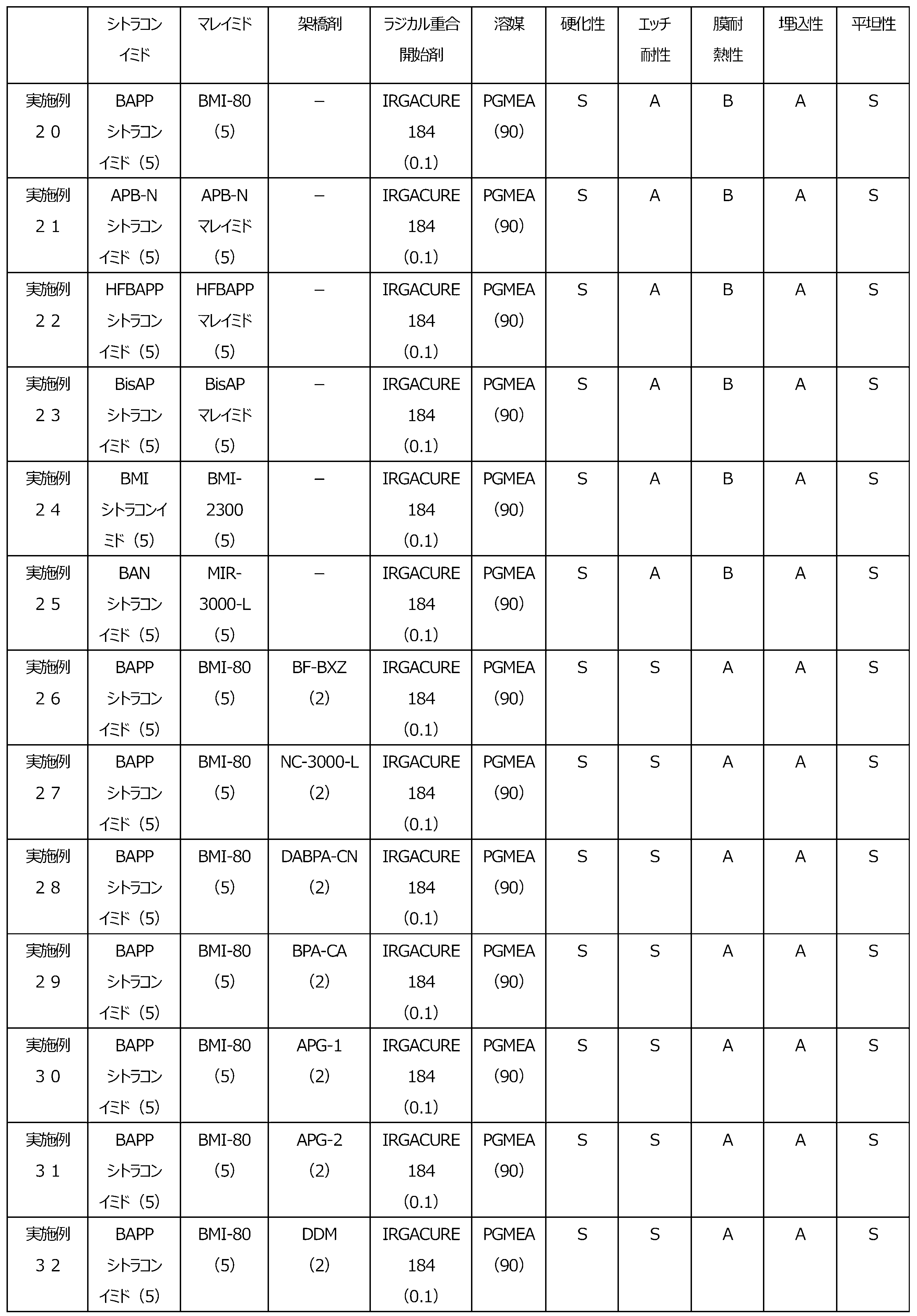
実施例1におけるリソグラフィー用膜形成用組成物を膜厚300nmのSiO2基板上に塗布して、240℃で60秒間、さらに400℃で120秒間ベークすることにより、膜厚70nmの下層膜を形成した。この下層膜上に、ArF用レジスト溶液を塗布し、130℃で60秒間ベークすることにより、膜厚140nmのフォトレジスト層を形成した。ArF用レジスト溶液としては、下記式(22)の化合物:5質量部、トリフェニルスルホニウムノナフルオロメタンスルホナート:1質量部、トリブチルアミン:2質量部、及びPGMEA:92質量部を配合して調製したものを用いた。
なお、下記式(22)の化合物は、次のように調製した。すなわち、2-メチル-2-メタクリロイルオキシアダマンタン4.15g、メタクリルロイルオキシ-γ-ブチロラクトン3.00g、3-ヒドロキシ-1-アダマンチルメタクリレート2.08g、アゾビスイソブチロニトリル0.38gを、テトラヒドロフラン80mLに溶解させて反応溶液とした。この反応溶液を、窒素雰囲気下、反応温度を63℃に保持して、22時間重合させた後、反応溶液を400mLのn-ヘキサン中に滴下した。このようにして得られる生成樹脂を凝固精製させ、生成した白色粉末をろ過し、減圧下40℃で一晩乾燥させて下記式で表される化合物を得た。

前記実施例1におけるリソグラフィー用下層膜形成用組成物の代わりに実施例2におけるリソグラフィー用下層膜形成用組成物を用いること以外は、実施例33と同様にして、ポジ型のレジストパターンを得た。評価結果を表3に示す。
前記実施例1におけるリソグラフィー用下層膜形成用組成物の代わりに実施例3におけるリソグラフィー用下層膜形成用組成物を用いること以外は、実施例33と同様にして、ポジ型のレジストパターンを得た。評価結果を表3に示す。
前記実施例1におけるリソグラフィー用下層膜形成用組成物の代わりに実施例4におけるリソグラフィー用下層膜形成用組成物を用いること以外は、実施例33と同様にして、ポジ型のレジストパターンを得た。評価結果を表3に示す。
下層膜の形成を行わないこと以外は、実施例33と同様にして、フォトレジスト層をSiO2基板上に直接形成し、ポジ型のレジストパターンを得た。評価結果を表3に示す。
実施例33~36、及び比較例3のそれぞれについて、得られた55nmL/S(1:1)及び80nmL/S(1:1)のレジストパターンの形状を(株)日立製作所製の電子顕微鏡(S-4800)を用いて観察した。現像後のレジストパターンの形状については、パターン倒れがなく、矩形性が良好なものを良好とし、そうでないものを不良として評価した。また、当該観察の結果、パターン倒れが無く、矩形性が良好な最小の線幅を解像性として評価の指標とした。さらに、良好なパターン形状を描画可能な最小の電子線エネルギー量を感度として、評価の指標とした。
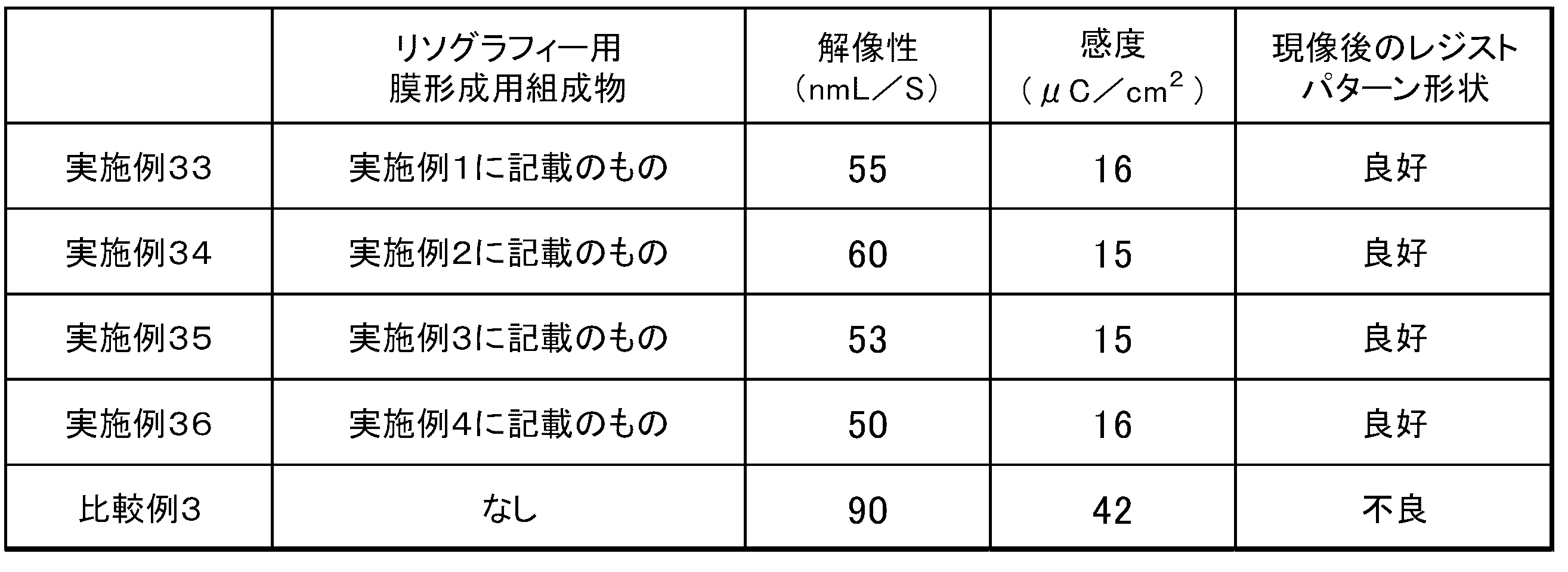
実施例1、実施例5および実施例6におけるリソグラフィー用膜形成用組成物を膜厚300nmのSiO2基板上に塗布して、240℃で60秒間、さらに400℃で120秒間ベークすることにより、膜厚80nmの下層膜を形成した。その後、光学顕微鏡にて膜表面を観察し、欠陥の有無を確認した。評価結果を表4に示す。
実施例1におけるリソグラフィー用膜形成用材料の代わりにBMI-80(大和化成工業(株)製)を用いた以外は、実施例37と同様にして、光学顕微鏡にて膜表面を観察し、欠陥の有無を確認した。評価結果を表4に示す。
実施例5におけるリソグラフィー用膜形成用材料の代わりにBMI-2300(大和化成工業(株)製)を用いた以外は、実施例38と同様にして、光学顕微鏡にて膜表面を観察し、欠陥の有無を確認した。評価結果を表4に示す。
A:欠陥無し
B:欠陥がほぼ無い
C:欠陥あり
なお、欠陥とは光学顕微鏡による膜表面の観察において確認される異物の存在をいう。

1000mL容量の四つ口フラスコ(底抜き型)に、合成実施例1-1で得られたBAPPシトラコンイミド(5質量%)およびBMI-80(5質量%)をシクロヘキサノンに溶解させた溶液を150g仕込み、撹拌しながら80℃まで加熱した。次いで、蓚酸水溶液(pH1.3)37.5gを加え、5分間攪拌後、30分静置した。これにより油相と水相に分離したので、水相を除去した。この操作を1回繰り返した後、得られた油相に、超純水37.5gを仕込み、5分間攪拌後、30分静置し、水相を除去した。この操作を3回繰り返した後、80℃に加熱しながらフラスコ内を200hPa以下に減圧することで、残留水分及びシクロヘキサノンを濃縮留去した。その後、ELグレードのシクロヘキサノン(関東化学社製試薬)を希釈し、10質量%に濃度調整を行うことにより、金属含有量の低減されたBAPPシトラコンイミドおよびBMI-80混合物のシクロヘキサノン溶液を得た。
蓚酸水溶液の代わりに、超純水を用いる以外は実施例40と同様に実施し、10質量%に濃度調整を行うことにより、BAPPシトラコンイミド/BMI-80混合物のシクロヘキサノン溶液を得た。

Claims (35)
- 式(0A)の基:

RAは、水素原子又は炭素数1~4のアルキル基であり、
RBは、炭素数1~4のアルキル基である)
を有する化合物;及び
式(0B)の基:

を含む、リソグラフィー用膜形成材料。 - 式(0A)の基を有する化合物が、2以上の式(0A)の基を有する、請求項1に記載のリソグラフィー用膜形成材料。
- 式(0B)の基を有する化合物が、2以上の式(0B)の基を有する、請求項1又は2に記載のリソグラフィー用膜形成材料。
- 式(0A)の基を有する化合物が、2つの式(0A)の基を有する化合物、又は式(0A)の基を有する化合物の付加重合樹脂である、請求項1~3のいずれか一項に記載のリソグラフィー用膜形成材料。
- 式(0B)の基を有する化合物が、2つの式(0B)の基を有する化合物、又は式(0B)の基を有する化合物の付加重合樹脂である、請求項1~4のいずれか一項に記載のリソグラフィー用膜形成材料。
- 式(0A)の基を有する化合物が、式(1A0)で表される、請求項1~5のいずれか一項に記載のリソグラフィー用膜形成材料

RA及びRBは前記のとおりであり、
Zはヘテロ原子を含んでいてもよい炭素数1~100の2価の炭化水素基である)。 - 式(0A)の基を有する化合物が、式(1A)で表される、請求項1~5のいずれか一項に記載のリソグラフィー用膜形成材料

RA及びRBは前記のとおりであり、
Xは、それぞれ独立して、単結合、-O-、-CH2-、-C(CH3)2-、-CO-、-C(CF3)2-、-CONH-又は-COO-であり、
Aは、単結合、酸素原子、又はヘテロ原子を含んでいてもよい炭素数1~80の2価の炭化水素基であり、
R1は、それぞれ独立して、ヘテロ原子を含んでいてもよい炭素数0~30の基であり、
m1は、それぞれ独立して、0~4の整数である)。 - Aが、単結合、酸素原子、-(CH2)p-、-CH2C(CH3)2CH2-、-(C(CH3)2)p-、-(O(CH2)q)p-、-(О(C6H4))p-、又は以下の構造のいずれかであり、


pは0~20の整数であり、
qは0~4の整数である、
請求項7に記載のリソグラフィー用膜形成材料。 - 式(0A)の基を有する化合物が、式(2A)で表される、請求項1~5のいずれか一項に記載のリソグラフィー用膜形成材料

RA及びRBは前記のとおりであり、
R2は、それぞれ独立して、ヘテロ原子を含んでいてもよい炭素数0~10の基であり、
m2は、それぞれ独立して、0~3の整数であり、
m2’は、それぞれ独立して、0~4の整数であり、
nは、0~4の整数である)。 - 式(0A)の基を有する化合物が、式(3A)で表される、請求項1~5のいずれか一項に記載のリソグラフィー用膜形成材料

RA及びRBは前記のとおりであり、
R3及びR4は、それぞれ独立して、ヘテロ原子を含んでいてもよい炭素数0~10の基であり、
m3は、それぞれ独立して、0~4の整数であり、
m4は、それぞれ独立して、0~4の整数であり、
nは、0~4の整数である)。 - 式(0B)の基を有する化合物が、式(1B0)で表される、請求項1~10のいずれか一項に記載のリソグラフィー用膜形成材料

Zはヘテロ原子を含んでいてもよい炭素数1~100の2価の炭化水素基である)。 - 式(0B)の基を有する化合物が、式(1B)で表される、請求項1~10のいずれか一項に記載のリソグラフィー用膜形成材料

Xは、それぞれ独立して、単結合、-O-、-CH2-、-C(CH3)2-、-CO-、-C(CF3)2-、-CONH-又は-COO-であり、
Aは、単結合、酸素原子、又はヘテロ原子を含んでいてもよい炭素数1~80の2価の炭化水素基であり、
R1は、それぞれ独立して、ヘテロ原子を含んでいてもよい炭素数0~30の基であり、
m1は、それぞれ独立して、0~4の整数である)。 - Aが、単結合、酸素原子、-(CH2)p-、-CH2C(CH3)2CH2-、-(C(CH3)2)p-、-(O(CH2)q)p-、-(О(C6H4))p-、又は以下の構造のいずれかであり、


pは0~20の整数であり、
qは、それぞれ独立して、0~4の整数である、
請求項12に記載のリソグラフィー用膜形成材料。 - 式(0B)の基を有する化合物が、式(2B)で表される、請求項1~10のいずれか一項に記載のリソグラフィー用膜形成材料

R2は、それぞれ独立して、ヘテロ原子を含んでいてもよい炭素数0~10の基であり、
m2は、それぞれ独立して、0~3の整数であり、
m2’は、それぞれ独立して、0~4の整数であり、
nは、0~4の整数である)。 - 式(0B)の基を有する化合物が、式(3B)で表される、請求項1~10のいずれか一項に記載のリソグラフィー用膜形成材料
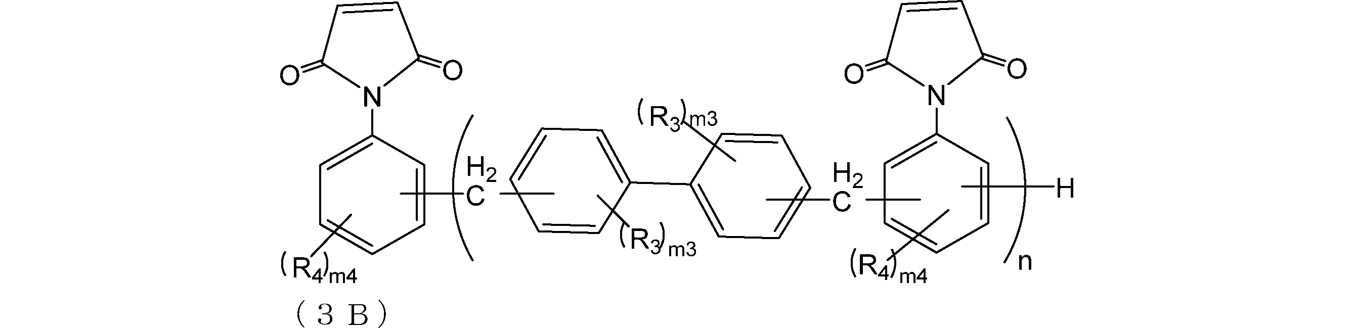
R3及びR4は、それぞれ独立して、ヘテロ原子を含んでいてもよい炭素数0~10の基であり、
m3は、それぞれ独立して、0~4の整数であり、
m4は、それぞれ独立して、0~4の整数であり、
nは、0~4の整数である)。 - 架橋剤をさらに含有する、請求項1~15のいずれか一項に記載のリソグラフィー用膜形成材料。
- 前記架橋剤が、フェノール化合物、エポキシ化合物、シアネート化合物、アミノ化合物、ベンゾオキサジン化合物、メラミン化合物、グアナミン化合物、グリコールウリル化合物、ウレア化合物、イソシアネート化合物及びアジド化合物からなる群より選ばれる少なくとも1種である、請求項16に記載のリソグラフィー用膜形成材料。
- 前記架橋剤が、少なくとも1つのアリル基を有する、請求項16又は17に記載のリソグラフィー用膜形成材料。
- 前記架橋剤の含有割合が、式(0A)の基を有する化合物と式(0B)の基を有する化合物との合計質量を100質量部とした場合に、0.1~100質量部である、請求項16~18のいずれか一項に記載のリソグラフィー用膜形成材料。
- 架橋促進剤をさらに含有する、請求項1~19のいずれか一項に記載のリソグラフィー用膜形成材料。
- 前記架橋促進剤が、アミン類、イミダゾール類、有機ホスフィン類、塩基発生剤、及びルイス酸からなる群より選ばれる少なくとも1種である、請求項20に記載のリソグラフィー用膜形成材料。
- 前記架橋促進剤の含有割合が、式(0A)の基を有する化合物と式(0B)の基を有する化合物との合計質量を100質量部とした場合に、0.01~5質量部である、請求項20又は21に記載のリソグラフィー用膜形成材料。
- ラジカル重合開始剤をさらに含有する、請求項1~22のいずれか一項に記載のリソグラフィー用膜形成材料。
- 前記ラジカル重合開始剤が、ケトン系光重合開始剤、有機過酸化物系重合開始剤及びアゾ系重合開始剤からなる群より選ばれる少なくとも1種である、請求項23に記載のリソグラフィー用膜形成材料。
- 前記ラジカル重合開始剤の含有割合が、式(0A)の基を有する化合物と式(0B)の基を有する化合物との合計質量を100質量部とした場合に、0.01~25質量部である、請求項23又は24に記載のリソグラフィー用膜形成材料。
- 請求項1~25のいずれか一項に記載のリソグラフィー用膜形成材料と溶媒とを含有する、リソグラフィー用膜形成用組成物。
- 酸発生剤をさらに含有する、請求項26に記載のリソグラフィー用膜形成用組成物。
- リソグラフィー用膜がリソグラフィー用下層膜である、請求項26又は27に記載のリソグラフィー用膜形成用組成物。
- 請求項28に記載のリソグラフィー用膜形成用組成物を用いて形成される、リソグラフィー用下層膜。
- 基板上に、請求項28に記載のリソグラフィー用膜形成用組成物を用いて下層膜を形成する工程、
該下層膜上に、少なくとも1層のフォトレジスト層を形成する工程、及び
該フォトレジスト層の所定の領域に放射線を照射し、現像を行う工程、
を含む、レジストパターン形成方法。 - 基板上に、請求項28に記載のリソグラフィー用膜形成用組成物を用いて下層膜を形成する工程、
該下層膜上に、珪素原子を含有するレジスト中間層膜材料を用いて中間層膜を形成する工程、
該中間層膜上に、少なくとも1層のフォトレジスト層を形成する工程、
該フォトレジスト層の所定の領域に放射線を照射し、現像してレジストパターンを形成する工程、
該レジストパターンをマスクとして前記中間層膜をエッチングする工程、
得られた中間層膜パターンをエッチングマスクとして前記下層膜をエッチングする工程、及び
得られた下層膜パターンをエッチングマスクとして基板をエッチングすることで基板にパターンを形成する工程、
を含む、回路パターン形成方法。 - 請求項1~25のいずれか一項に記載のリソグラフィー用膜形成材料を、溶媒に溶解させて有機相を得る工程と、
前記有機相と酸性の水溶液とを接触させて、前記リソグラフィー用膜形成材料中の不純物を抽出する第一抽出工程と、
を含み、
前記有機相を得る工程で用いる溶媒が、水と任意に混和しない溶媒を含む、精製方法。 - 前記酸性の水溶液が、鉱酸水溶液又は有機酸水溶液であり、
前記鉱酸水溶液が、塩酸、硫酸、硝酸及びリン酸からなる群より選ばれる1種以上を含み、
前記有機酸水溶液が、酢酸、プロピオン酸、蓚酸、マロン酸、コハク酸、フマル酸、マレイン酸、酒石酸、クエン酸、メタンスルホン酸、フェノールスルホン酸、p-トルエンスルホン酸及びトリフルオロ酢酸からなる群より選ばれる1種以上を含む、請求項32に記載の精製方法。 - 前記水と任意に混和しない溶媒が、トルエン、キシレン、2-ヘプタノン、シクロヘキサノン、シクロペンタノン、シクロペンチルメチルエーテル、メチルテトラヒドロフラン、ブタノール、ヘキサノール、メチルイソブチルケトン、プロピレングリコールモノメチルエーテルアセテート、酢酸ブチル、酢酸イソブチル、酢酸イソアミル及び酢酸エチルからなる群より選ばれる1種以上の溶媒である、請求項32又は33に記載の精製方法。
- 前記第一抽出工程後、前記有機相を、水に接触させて、前記リソグラフィー用膜形成材料中の不純物を抽出する第二抽出工程をさらに含む、請求項32~34のいずれか一項に記載の精製方法。
Priority Applications (5)
| Application Number | Priority Date | Filing Date | Title |
|---|---|---|---|
| CN201980040257.0A CN112368644A (zh) | 2018-08-20 | 2019-08-08 | 光刻用膜形成材料、光刻用膜形成用组合物、光刻用下层膜和图案形成方法 |
| KR1020207032229A KR20210045357A (ko) | 2018-08-20 | 2019-08-08 | 리소그래피용 막형성재료, 리소그래피용 막형성용 조성물, 리소그래피용 하층막 및 패턴 형성방법 |
| EP19852216.1A EP3842863A4 (en) | 2018-08-20 | 2019-08-08 | FILM EDUCATION MATERIAL FOR LITHOGRAPHY, COMPOSITION FOR FILM FORMATION FOR LITHOGRAPHY, LAYER FILM FOR LITHOGRAPHY AND PATTERN GENERATION PROCESS |
| JP2020538309A JP7256482B2 (ja) | 2018-08-20 | 2019-08-08 | リソグラフィー用膜形成材料、リソグラフィー用膜形成用組成物、リソグラフィー用下層膜及びパターン形成方法 |
| US17/268,038 US20210165327A1 (en) | 2018-08-20 | 2019-08-08 | Film forming material for lithography, composition for film formation for lithography, underlayer film for lithography, and method for forming pattern |
Applications Claiming Priority (2)
| Application Number | Priority Date | Filing Date | Title |
|---|---|---|---|
| JP2018153839 | 2018-08-20 | ||
| JP2018-153839 | 2018-08-20 |
Publications (1)
| Publication Number | Publication Date |
|---|---|
| WO2020039966A1 true WO2020039966A1 (ja) | 2020-02-27 |
Family
ID=69593144
Family Applications (1)
| Application Number | Title | Priority Date | Filing Date |
|---|---|---|---|
| PCT/JP2019/031399 Ceased WO2020039966A1 (ja) | 2018-08-20 | 2019-08-08 | リソグラフィー用膜形成材料、リソグラフィー用膜形成用組成物、リソグラフィー用下層膜及びパターン形成方法 |
Country Status (7)
| Country | Link |
|---|---|
| US (1) | US20210165327A1 (ja) |
| EP (1) | EP3842863A4 (ja) |
| JP (1) | JP7256482B2 (ja) |
| KR (1) | KR20210045357A (ja) |
| CN (1) | CN112368644A (ja) |
| TW (1) | TW202018420A (ja) |
| WO (1) | WO2020039966A1 (ja) |
Cited By (1)
| Publication number | Priority date | Publication date | Assignee | Title |
|---|---|---|---|---|
| US20240319600A1 (en) * | 2021-03-02 | 2024-09-26 | Mitsubishi Gas Chemical Company, Inc. | Film forming material for lithography, composition, underlayer film for lithography, and method for forming pattern |
Families Citing this family (4)
| Publication number | Priority date | Publication date | Assignee | Title |
|---|---|---|---|---|
| KR102772578B1 (ko) * | 2019-05-27 | 2025-02-26 | 미쯔비시 가스 케미칼 컴파니, 인코포레이티드 | 리소그래피용 하층막 형성용 조성물, 리소그래피용 하층막 및 패턴 형성방법 및 정제방법 |
| US12195566B2 (en) | 2019-06-28 | 2025-01-14 | Mitsubishi Gas Chemical Company, Inc. | Film, laminate, semiconductor wafer with film layer, substrate for mounting semiconductor with film layer, and semiconductor device |
| CN118382674A (zh) * | 2021-12-14 | 2024-07-23 | 阿萨达股份公司 | 具有改进的特性的新型组合物 |
| IL312591B2 (en) * | 2021-12-14 | 2025-10-01 | Arxada Ag | Preparations with improved properties |
Citations (20)
| Publication number | Priority date | Publication date | Assignee | Title |
|---|---|---|---|---|
| JPH03185015A (ja) * | 1989-12-14 | 1991-08-13 | Showa Highpolymer Co Ltd | 熱硬化性ポリアミドおよびその組成物 |
| JPH1112258A (ja) | 1997-06-20 | 1999-01-19 | Shikoku Chem Corp | 3−アリールジヒドロ−1,3−ベンゾオキサジン化合物の製法 |
| JPH11258802A (ja) * | 1998-03-16 | 1999-09-24 | Fuji Photo Film Co Ltd | ネガ型レジスト組成物 |
| JP2001026571A (ja) | 1999-05-27 | 2001-01-30 | Enichem Spa | ジアミノジフェニルメタンとその高級同族体の製造方法 |
| JP2002334869A (ja) | 2001-02-07 | 2002-11-22 | Tokyo Electron Ltd | シリコン窒化膜の形成方法、形成装置及びこの形成装置の洗浄前処理方法 |
| WO2004009708A1 (ja) | 2002-07-19 | 2004-01-29 | Nippon Steel Chemical Co., Ltd. | 硬化性樹脂組成物 |
| JP2004177668A (ja) | 2002-11-27 | 2004-06-24 | Tokyo Ohka Kogyo Co Ltd | 多層レジストプロセス用下層膜形成材料およびこれを用いた配線形成方法 |
| WO2004066377A1 (ja) | 2003-01-24 | 2004-08-05 | Tokyo Electron Limited | 被処理基板上にシリコン窒化膜を形成するcvd方法 |
| JP2004271838A (ja) | 2003-03-07 | 2004-09-30 | Shin Etsu Chem Co Ltd | レジスト下層膜材料ならびにパターン形成方法 |
| JP2004352670A (ja) | 2003-05-29 | 2004-12-16 | Shikoku Chem Corp | ベンゾオキサジン化合物、プリプレグ、積層板及びプリント配線板 |
| JP2005250434A (ja) | 2004-02-04 | 2005-09-15 | Shin Etsu Chem Co Ltd | レジスト下層膜材料ならびにパターン形成方法 |
| JP2007226204A (ja) | 2006-01-25 | 2007-09-06 | Shin Etsu Chem Co Ltd | 反射防止膜材料、基板、及びパターン形成方法 |
| JP2007226170A (ja) | 2006-01-27 | 2007-09-06 | Shin Etsu Chem Co Ltd | 反射防止膜材料、反射防止膜を有する基板及びパターン形成方法 |
| WO2009072465A1 (ja) | 2007-12-07 | 2009-06-11 | Mitsubishi Gas Chemical Company, Inc. | リソグラフィー用下層膜形成組成物及び多層レジストパターン形成方法 |
| JP2010519340A (ja) * | 2006-12-06 | 2010-06-03 | プロメラス, エルエルシー | 直接感光性ポリマー組成物およびその方法 |
| WO2011034062A1 (ja) | 2009-09-15 | 2011-03-24 | 三菱瓦斯化学株式会社 | 芳香族炭化水素樹脂及びリソグラフィー用下層膜形成組成物 |
| WO2011108524A1 (ja) | 2010-03-02 | 2011-09-09 | 三菱瓦斯化学株式会社 | 樹脂組成物、プリプレグ、および積層板 |
| WO2013024779A1 (ja) | 2011-08-12 | 2013-02-21 | 三菱瓦斯化学株式会社 | リソグラフィー用下層膜形成材料、リソグラフィー用下層膜及びパターン形成方法 |
| WO2015080240A1 (ja) | 2013-11-29 | 2015-06-04 | 三菱瓦斯化学株式会社 | 化合物又は樹脂の精製方法 |
| WO2018016614A1 (ja) | 2016-07-21 | 2018-01-25 | 三菱瓦斯化学株式会社 | 化合物、樹脂、組成物及びパターン形成方法 |
Family Cites Families (15)
| Publication number | Priority date | Publication date | Assignee | Title |
|---|---|---|---|---|
| US4079041A (en) * | 1975-06-18 | 1978-03-14 | Ciba-Geigy Corporation | Crosslinkable polymeric compounds |
| NL9101750A (nl) * | 1991-10-21 | 1993-05-17 | Dsm Nv | Polymeersamenstelling. |
| US20040029044A1 (en) * | 2002-08-08 | 2004-02-12 | 3M Innovative Properties Company | Photocurable composition |
| US20130025495A1 (en) * | 2010-01-11 | 2013-01-31 | Isp Investments Inc. | Compositions comprising a reactive monomer and uses thereof |
| JP5615600B2 (ja) * | 2010-06-09 | 2014-10-29 | 富士フイルム株式会社 | インクジェット記録用インク組成物、インクジェット記録方法及びインクジェット印画物 |
| WO2012172816A1 (ja) * | 2011-06-17 | 2012-12-20 | コニカミノルタホールディングス株式会社 | 光硬化性インクジェットインク |
| US8697336B2 (en) * | 2011-12-15 | 2014-04-15 | Az Electronic Materials Usa Corp. | Composition for forming a developable bottom antireflective coating |
| TWI483071B (zh) * | 2013-03-01 | 2015-05-01 | Chi Mei Corp | 彩色濾光片用感光性樹脂組成物及其應用 |
| US9422376B2 (en) * | 2013-09-16 | 2016-08-23 | Sumitomo Bakelite Co., Ltd. | Amine treated maleic anhydride polymers, compositions and applications thereof |
| US20160237311A1 (en) * | 2013-09-26 | 2016-08-18 | Farhad G. Mizori | Low dielectric constant, low dielectric dissipation factor coatings, films and adhesives |
| TWI659013B (zh) * | 2014-03-13 | 2019-05-11 | Mitsubishi Gas Chemical Company, Inc. | 化合物、樹脂、微影蝕刻用底層膜形成材料、微影蝕刻用底層膜、圖型形成方法、及化合物或樹脂的純化方法 |
| CN107148452B (zh) * | 2014-11-06 | 2018-10-09 | 三菱瓦斯化学株式会社 | 树脂组合物、预浸料、覆金属箔层叠板、树脂复合片及印刷电路板 |
| JP6660890B2 (ja) * | 2015-01-21 | 2020-03-11 | 日本化薬株式会社 | 芳香族アミン樹脂、エポキシ樹脂組成物及びその硬化物 |
| TWI744302B (zh) * | 2016-05-19 | 2021-11-01 | 日商捷恩智股份有限公司 | 聚合性組成物、液晶複合體、光學各向異性體、液晶顯示元件及其用途 |
| WO2018011674A1 (en) * | 2016-07-11 | 2018-01-18 | Soreq Nuclear Research Center | Bismaleimide-based solution for inkjet ink for three dimensional printing |
-
2019
- 2019-08-08 JP JP2020538309A patent/JP7256482B2/ja active Active
- 2019-08-08 EP EP19852216.1A patent/EP3842863A4/en not_active Withdrawn
- 2019-08-08 WO PCT/JP2019/031399 patent/WO2020039966A1/ja not_active Ceased
- 2019-08-08 KR KR1020207032229A patent/KR20210045357A/ko not_active Withdrawn
- 2019-08-08 US US17/268,038 patent/US20210165327A1/en not_active Abandoned
- 2019-08-08 CN CN201980040257.0A patent/CN112368644A/zh active Pending
- 2019-08-14 TW TW108128863A patent/TW202018420A/zh unknown
Patent Citations (20)
| Publication number | Priority date | Publication date | Assignee | Title |
|---|---|---|---|---|
| JPH03185015A (ja) * | 1989-12-14 | 1991-08-13 | Showa Highpolymer Co Ltd | 熱硬化性ポリアミドおよびその組成物 |
| JPH1112258A (ja) | 1997-06-20 | 1999-01-19 | Shikoku Chem Corp | 3−アリールジヒドロ−1,3−ベンゾオキサジン化合物の製法 |
| JPH11258802A (ja) * | 1998-03-16 | 1999-09-24 | Fuji Photo Film Co Ltd | ネガ型レジスト組成物 |
| JP2001026571A (ja) | 1999-05-27 | 2001-01-30 | Enichem Spa | ジアミノジフェニルメタンとその高級同族体の製造方法 |
| JP2002334869A (ja) | 2001-02-07 | 2002-11-22 | Tokyo Electron Ltd | シリコン窒化膜の形成方法、形成装置及びこの形成装置の洗浄前処理方法 |
| WO2004009708A1 (ja) | 2002-07-19 | 2004-01-29 | Nippon Steel Chemical Co., Ltd. | 硬化性樹脂組成物 |
| JP2004177668A (ja) | 2002-11-27 | 2004-06-24 | Tokyo Ohka Kogyo Co Ltd | 多層レジストプロセス用下層膜形成材料およびこれを用いた配線形成方法 |
| WO2004066377A1 (ja) | 2003-01-24 | 2004-08-05 | Tokyo Electron Limited | 被処理基板上にシリコン窒化膜を形成するcvd方法 |
| JP2004271838A (ja) | 2003-03-07 | 2004-09-30 | Shin Etsu Chem Co Ltd | レジスト下層膜材料ならびにパターン形成方法 |
| JP2004352670A (ja) | 2003-05-29 | 2004-12-16 | Shikoku Chem Corp | ベンゾオキサジン化合物、プリプレグ、積層板及びプリント配線板 |
| JP2005250434A (ja) | 2004-02-04 | 2005-09-15 | Shin Etsu Chem Co Ltd | レジスト下層膜材料ならびにパターン形成方法 |
| JP2007226204A (ja) | 2006-01-25 | 2007-09-06 | Shin Etsu Chem Co Ltd | 反射防止膜材料、基板、及びパターン形成方法 |
| JP2007226170A (ja) | 2006-01-27 | 2007-09-06 | Shin Etsu Chem Co Ltd | 反射防止膜材料、反射防止膜を有する基板及びパターン形成方法 |
| JP2010519340A (ja) * | 2006-12-06 | 2010-06-03 | プロメラス, エルエルシー | 直接感光性ポリマー組成物およびその方法 |
| WO2009072465A1 (ja) | 2007-12-07 | 2009-06-11 | Mitsubishi Gas Chemical Company, Inc. | リソグラフィー用下層膜形成組成物及び多層レジストパターン形成方法 |
| WO2011034062A1 (ja) | 2009-09-15 | 2011-03-24 | 三菱瓦斯化学株式会社 | 芳香族炭化水素樹脂及びリソグラフィー用下層膜形成組成物 |
| WO2011108524A1 (ja) | 2010-03-02 | 2011-09-09 | 三菱瓦斯化学株式会社 | 樹脂組成物、プリプレグ、および積層板 |
| WO2013024779A1 (ja) | 2011-08-12 | 2013-02-21 | 三菱瓦斯化学株式会社 | リソグラフィー用下層膜形成材料、リソグラフィー用下層膜及びパターン形成方法 |
| WO2015080240A1 (ja) | 2013-11-29 | 2015-06-04 | 三菱瓦斯化学株式会社 | 化合物又は樹脂の精製方法 |
| WO2018016614A1 (ja) | 2016-07-21 | 2018-01-25 | 三菱瓦斯化学株式会社 | 化合物、樹脂、組成物及びパターン形成方法 |
Non-Patent Citations (1)
| Title |
|---|
| See also references of EP3842863A4 |
Cited By (1)
| Publication number | Priority date | Publication date | Assignee | Title |
|---|---|---|---|---|
| US20240319600A1 (en) * | 2021-03-02 | 2024-09-26 | Mitsubishi Gas Chemical Company, Inc. | Film forming material for lithography, composition, underlayer film for lithography, and method for forming pattern |
Also Published As
| Publication number | Publication date |
|---|---|
| JP7256482B2 (ja) | 2023-04-12 |
| KR20210045357A (ko) | 2021-04-26 |
| US20210165327A1 (en) | 2021-06-03 |
| TW202018420A (zh) | 2020-05-16 |
| CN112368644A (zh) | 2021-02-12 |
| EP3842863A1 (en) | 2021-06-30 |
| EP3842863A4 (en) | 2021-11-03 |
| JPWO2020039966A1 (ja) | 2021-08-26 |
Similar Documents
| Publication | Publication Date | Title |
|---|---|---|
| CN110637256B (zh) | 光刻用膜形成材料、光刻用膜形成用组合物、光刻用下层膜及图案形成方法 | |
| KR102703439B1 (ko) | 리소그래피용 막형성재료, 리소그래피용 막형성용 조성물, 리소그래피용 하층막 및 패턴 형성방법 | |
| JP7256482B2 (ja) | リソグラフィー用膜形成材料、リソグラフィー用膜形成用組成物、リソグラフィー用下層膜及びパターン形成方法 | |
| JP7438483B2 (ja) | リソグラフィー用膜形成材料、リソグラフィー用膜形成用組成物、リソグラフィー用下層膜及びパターン形成方法 | |
| JP6889873B2 (ja) | リソグラフィー用膜形成材料、リソグラフィー用膜形成用組成物、リソグラフィー用下層膜及びパターン形成方法 | |
| CN113574092A (zh) | 光刻用膜形成材料、光刻用膜形成用组合物、光刻用下层膜、图案形成方法、及纯化方法 | |
| JP7415310B2 (ja) | リソグラフィー用膜形成材料、リソグラフィー用膜形成用組成物、リソグラフィー用下層膜及びパターン形成方法 | |
| JP7643336B2 (ja) | リソグラフィー用膜形成材料、リソグラフィー用膜形成用組成物、リソグラフィー用下層膜及びパターン形成方法 | |
| JP7258279B2 (ja) | リソグラフィー用膜形成材料、リソグラフィー用膜形成用組成物、リソグラフィー用下層膜及びパターン形成方法 | |
| JP7828561B2 (ja) | リソグラフィー用膜形成材料、組成物、リソグラフィー用下層膜、及びパターン形成方法 |
Legal Events
| Date | Code | Title | Description |
|---|---|---|---|
| 121 | Ep: the epo has been informed by wipo that ep was designated in this application |
Ref document number: 19852216 Country of ref document: EP Kind code of ref document: A1 |
|
| ENP | Entry into the national phase |
Ref document number: 2020538309 Country of ref document: JP Kind code of ref document: A |
|
| ENP | Entry into the national phase |
Ref document number: 20207032229 Country of ref document: KR Kind code of ref document: A |
|
| NENP | Non-entry into the national phase |
Ref country code: DE |
|
| ENP | Entry into the national phase |
Ref document number: 2019852216 Country of ref document: EP Effective date: 20210322 |