WO2020044978A1 - Dispositif de mesure et procédé d'évaluation - Google Patents
Dispositif de mesure et procédé d'évaluation Download PDFInfo
- Publication number
- WO2020044978A1 WO2020044978A1 PCT/JP2019/030791 JP2019030791W WO2020044978A1 WO 2020044978 A1 WO2020044978 A1 WO 2020044978A1 JP 2019030791 W JP2019030791 W JP 2019030791W WO 2020044978 A1 WO2020044978 A1 WO 2020044978A1
- Authority
- WO
- WIPO (PCT)
- Prior art keywords
- electrodes
- microorganism
- solid electrolyte
- substrate
- electrode
- Prior art date
- Legal status (The legal status is an assumption and is not a legal conclusion. Google has not performed a legal analysis and makes no representation as to the accuracy of the status listed.)
- Ceased
Links
Images




Classifications
-
- C—CHEMISTRY; METALLURGY
- C12—BIOCHEMISTRY; BEER; SPIRITS; WINE; VINEGAR; MICROBIOLOGY; ENZYMOLOGY; MUTATION OR GENETIC ENGINEERING
- C12Q—MEASURING OR TESTING PROCESSES INVOLVING ENZYMES, NUCLEIC ACIDS OR MICROORGANISMS; COMPOSITIONS OR TEST PAPERS THEREFOR; PROCESSES OF PREPARING SUCH COMPOSITIONS; CONDITION-RESPONSIVE CONTROL IN MICROBIOLOGICAL OR ENZYMOLOGICAL PROCESSES
- C12Q1/00—Measuring or testing processes involving enzymes, nucleic acids or microorganisms; Compositions therefor; Processes of preparing such compositions
- C12Q1/02—Measuring or testing processes involving enzymes, nucleic acids or microorganisms; Compositions therefor; Processes of preparing such compositions involving viable microorganisms
- C12Q1/22—Testing for sterility conditions
-
- G—PHYSICS
- G01—MEASURING; TESTING
- G01N—INVESTIGATING OR ANALYSING MATERIALS BY DETERMINING THEIR CHEMICAL OR PHYSICAL PROPERTIES
- G01N27/00—Investigating or analysing materials by the use of electric, electrochemical, or magnetic means
- G01N27/26—Investigating or analysing materials by the use of electric, electrochemical, or magnetic means by investigating electrochemical variables; by using electrolysis or electrophoresis
- G01N27/403—Cells and electrode assemblies
- G01N27/406—Cells and probes with solid electrolytes
-
- C—CHEMISTRY; METALLURGY
- C12—BIOCHEMISTRY; BEER; SPIRITS; WINE; VINEGAR; MICROBIOLOGY; ENZYMOLOGY; MUTATION OR GENETIC ENGINEERING
- C12Q—MEASURING OR TESTING PROCESSES INVOLVING ENZYMES, NUCLEIC ACIDS OR MICROORGANISMS; COMPOSITIONS OR TEST PAPERS THEREFOR; PROCESSES OF PREPARING SUCH COMPOSITIONS; CONDITION-RESPONSIVE CONTROL IN MICROBIOLOGICAL OR ENZYMOLOGICAL PROCESSES
- C12Q1/00—Measuring or testing processes involving enzymes, nucleic acids or microorganisms; Compositions therefor; Processes of preparing such compositions
- C12Q1/02—Measuring or testing processes involving enzymes, nucleic acids or microorganisms; Compositions therefor; Processes of preparing such compositions involving viable microorganisms
- C12Q1/04—Determining presence or kind of microorganism; Use of selective media for testing antibiotics or bacteriocides; Compositions containing a chemical indicator therefor
-
- G—PHYSICS
- G01—MEASURING; TESTING
- G01N—INVESTIGATING OR ANALYSING MATERIALS BY DETERMINING THEIR CHEMICAL OR PHYSICAL PROPERTIES
- G01N27/00—Investigating or analysing materials by the use of electric, electrochemical, or magnetic means
- G01N27/26—Investigating or analysing materials by the use of electric, electrochemical, or magnetic means by investigating electrochemical variables; by using electrolysis or electrophoresis
- G01N27/28—Electrolytic cell components
- G01N27/30—Electrodes, e.g. test electrodes; Half-cells
- G01N27/327—Biochemical electrodes, e.g. electrical or mechanical details for in vitro measurements
Definitions
- the present invention relates to a measuring device and an evaluation method.
- microorganisms that cause diseases using plants as hosts and microorganisms that cause infectious diseases using animals including humans as hosts are known.
- plant diseases caused by microorganisms are known.
- a control method for example, there is a method of spraying a drug or the like, and / or a method of destroying a plant in a range where the disease occurs, and generally, a microorganism causing the disease is used. It is considered that early identification and early identification of the range in which the disease is occurring are useful as methods for minimizing the damage of the disease.
- Patent Document 1 discloses “a method for detecting strawberry powdery mildew (Sphaerotheca aphanis) including the following steps: 1) DNA obtained from a strawberry plant, and an oligonucleotide represented by SEQ ID NO: 1. And a step of amplifying DNA using a primer pair consisting of the oligonucleotide shown in SEQ ID NO: 2; and 2) a step of detecting the obtained DNA amplification product.
- Patent Literature 2 discloses an endoscope cleaning management system and an endoscope cleaning aiming to ensure a cleaning level of an endoscope and to obtain a sufficient disinfection effect. Management methods have been proposed.
- Patent Document 1 Although it is possible to detect powdery mildew generated in strawberries, it requires an operation having expertise such as amplifying DNA obtained from strawberries as a sample using specific primers, And it was difficult to detect the above-mentioned disease on site.
- medical devices such as endoscopes, a culture method, an ATP (adenosine triphosphate) measurement method, and the like are conventionally known as methods for confirming the cleaning effect.
- a culture method many methods are required until a result is obtained. It takes time and effort.
- the ATP measurement method which is preferable in Patent Document 2
- JP-A-2015-150224 JP-A-2015-177914, JP-A-2018-130473, JP-A-2017-202128, and the like disclose the presence of pathogenic microorganisms as a method for confirming the effect of the cleaning treatment to which these techniques are applied. Development of a method that can be evaluated has been desired.
- the present inventor has found that the above object can be achieved by the following configuration.
- a solid electrolyte for contacting with a test object and capturing at least one kind of biological particles selected from the group consisting of microorganisms of the test object and particles derived from the microorganisms; Having two electrodes, of the biosensor arranged so that the solid electrolyte and the electrode are in contact with each other, a voltage application unit for applying a voltage between the electrodes, and when the voltage is applied, A detection unit for measuring a current value flowing between the electrodes, the current value, the presence or absence of the previously stored current value and the biological particles, the growth state of the microorganism, and the expression of pathogenicity of the microorganism A calculation unit for providing information derived from the microorganism by comparing a reference value defining at least one type of factor selected from the group consisting of the presence or absence of the microorganism with a reference value.
- the biosensor includes a first substrate, a substrate with a solid electrode having the solid electrolyte disposed on the first substrate, and a second substrate, and at least one disposed on the second substrate.
- the measuring device according to any one of [1] to [4], wherein at least one of the electrodes is a comb-shaped electrode having a comb shape.
- the information derived from the microorganism is information for evaluating a risk of disease occurrence in a plant caused by the microorganism.
- the biological particles are phytofutra, botrytis, plasmopara, sphaeroteca, alternaria, uromyces, ustilago, facopsora, barkholderia, xanthomonas , Xylella spp., Pseudomonas spp., Erwinia spp., Streptomyces spp., Candidatus liberibactere in citrus, and at least one microorganism selected from the group consisting of Candidatus flomobacter spp. In strawberry.
- the measuring device according to any one of [1] to [6].
- the diseases in the above-mentioned plants include powdery mildew, rust, spot disease, wilt, root and stem disease, ear disease, fruit rot, seedling wilt disease, clubroot, witches' broom, and The measurement device according to [6] or [7], wherein the measurement device is at least one selected from the group consisting of: leaf blight disease.
- the microorganisms are arranged by the remote communication connection between the measuring device according to any one of [1] to [8] and the measuring device arranged in each section.
- a terminal that obtains information for evaluating the risk of the occurrence of a disease in the test object from the measurement device from the measurement device, and the agricultural land management system, wherein the information for each section is displayed on the terminal.
- a farmland management system that is configured as possible.
- a measurement device that can easily provide information for determining the risk of disease occurrence in a plant even on site even if the operator does not have specialized knowledge.
- a method for evaluating the risk of disease occurrence in plants caused by microorganisms and a farmland management system can be provided.
- a measuring device that can easily detect the presence of a pathogenic microorganism in a target object, such as a medical device, in which a microorganism that causes an infectious disease of an animal including a human may be present. Can be provided. Further, a method for evaluating the cleanliness of medical equipment can be provided.
- FIG. 3 is an exploded perspective view of a biosensor that can be used in the measurement device according to the embodiment of the present invention. It is a front view of the part which contacts a solid electrolyte in a 1st electrode and a 2nd electrode. It is a perspective view showing the board
- substrate It is a schematic diagram showing a mode that a solid electrolyte is made to contact a plant organ.
- FIG. 2 is a perspective view of a biosensor formed by joining a substrate with a solid electrolyte and a substrate with an electrode via a spacer.
- FIG. 4 is a partially enlarged view around a sensor insertion port in a state where a biosensor is inserted into a main body.
- FIG. 8 is a sectional view taken along the line AA ′ in FIG. 7.
- 2 is a configuration of main electronic components housed in a housing of the measurement device.
- FIG. 4 is a schematic graph showing a relationship between a current value obtained from each of the sample D1 and the sample D2 and a voltage application time (measurement time) when a predetermined voltage is applied between the electrodes (constant potential measurement). is there.
- FIG. 9 is a perspective view of a substrate with electrodes included in a biosensor that can be used in the measurement device according to the second embodiment of the present invention. It is a lineblock diagram of a crop management system concerning an embodiment of the present invention.
- A), B) It is a schematic diagram which shows an example of the structure of the tube (tube) which is a component member of an endoscope.
- FIG. 5 is a graph showing the relationship between the concentration of MR-1 (OD 600 value) and the slope of the “time-current value” curve when the current value rises in a test example.
- FIG. 4 is a graph showing measurement results of current values obtained by smearing MR-1 culture solutions having different concentrations on a riboflavin-containing LB agar medium in Test Examples.
- 18 is a graph showing the relationship between the concentration of MR-1 (the logarithm of the OD 600 value) and the time until the current value reaches the maximum value, as shown in FIG. 5 is a graph showing an analysis result by differential pulse voltammetry (DPV) of a result obtained in a test example.
- DUV differential pulse voltammetry
- the measuring device is brought into contact with a test object and captures at least one kind of biological particles selected from the group consisting of microorganisms of the test object and particles derived from the microorganisms.
- a solid electrolyte for, and at least two electrodes, of the biosensor arranged so that the solid electrolyte and the electrodes are in contact, a voltage application unit for applying a voltage between the electrodes, When a voltage is applied, a detection unit for measuring a current value flowing between the electrodes, a current value stored in advance and the presence or absence of the biological particles, a growth state of the microorganism, and a pathogen of the microorganism.
- a configuration of an example of the measuring device according to the embodiment of the present invention will be described with reference to the drawings.
- FIG. 1 is an exploded perspective view of a biosensor that can be used in the measurement device according to the embodiment of the present invention.
- the biosensor 100 includes a first substrate 101 and a solid electrolyte 102 (in FIG. 1, the first substrate 101 is disposed so as to be in contact with an electrode to be described later).
- the solid electrolyte 102 is disposed so that the surface thereof is in contact with the first electrode 106 and the second electrode 107 via the spacer 104, but is applicable to the measuring device according to the embodiment of the present invention.
- the biosensor is not limited to the above, and may be in a form in which the solid electrolyte contacts the first electrode and the second electrode without using a spacer.
- the solid electrolyte 102 contains a substance serving as an electron source and / or an electron transfer substance
- the solid electrolyte is formed on the first substrate provided on the second substrate of the electrode-equipped substrate. It may be arranged to be in contact with the electrode and the second electrode. That is, in this embodiment, the biosensor does not have the spacer and the first substrate, and such a biosensor can be applied to the measuring device according to the embodiment of the present invention.
- the materials of the first substrate 101, the spacer 104, and the second substrate 105 are not particularly limited, but generally a substance having an insulating property (insulator) is preferable.
- insulator an organic material and an inorganic material Etc. can be used. Note that in this specification, a substance whose electric resistivity is 10 6 ( ⁇ ⁇ m) or more is preferable as an insulator.
- the organic material is not particularly limited, but may be (meth) acrylic resin, styrene resin, vinyl resin, polyolefin resin, polyester resin, polyurethane resin, polyamide resin, polycarbonate resin, polydiene resin, epoxy resin.
- the resin include a resin, a silicone-based resin, at least one resin selected from the group consisting of a cellulose-based polymer and a chitosan-based polymer, and a copolymer of monomers constituting these resins.
- the inorganic material is not particularly limited, and examples thereof include glass.
- the biosensor 100 is a two-electrode sensor in which two electrodes, that is, a first electrode 106 and a second electrode 107 are arranged on a second substrate 105.
- the first electrode 106 and the second electrode 107 are electrodes for electrochemically detecting biological particles trapped on the solid electrolyte, and can use a known electrode material, for example, gold (Au), silver ( Ag), platinum (Pt), and metal materials such as palladium (Pd).
- FIG. 2 is a front view of a portion of the first electrode 106 and the second electrode 107 that comes into contact with the solid electrolyte 102.
- Each of the first electrode 106 and the second electrode 107 is a comb-shaped electrode having a comb-like structure, and the comb teeth of the first electrode 106 and the comb teeth of the second electrode 107 are alternately arranged. Structure.
- the first electrode 106 has four comb teeth and the second electrode 107 has three comb teeth.
- the present invention is not limited to the above, and the number of comb teeth is appropriately determined. Can be selected.
- the comb teeth are arranged at equal intervals of a distance W1, the distance between the tip of the comb tooth of the first electrode 106 and the second electrode 107, and the comb of the second electrode 107.
- the distance (not shown) between the tip of the tooth and the second electrode 107 is a distance W2.
- the distance W1 and the distance W2 are not particularly limited, and the microorganisms (possibly) contained in the inspection object and / or particles derived from the microorganisms (hereinafter, “biological particles to be detected”) ) Can be appropriately selected depending on the size.
- biological particles having a size corresponding to the shortest distance between the first electrode 106 and the second electrode 107 can be detected.
- biological particles having a size equal to or greater than the smaller distance between W1 and W2 can be detected.
- the shortest distance between the two electrodes is not particularly limited, but is generally preferably 50 nm to 10 ⁇ m.
- the distance between the two electrodes is preferably equal to or smaller than the size of the biological particle to be detected.
- the biological particles to be detected are not particularly limited, but when the test object is a plant, phytohutra, botrytis, plasmopara, sphaeroteca, alternaria, uromyces, ustyrago , Facopsora spp., Burkholderia spp., Xanthomonas spp., Xylella spp., Pseudomonas spp., Erwinia spp., Streptomyces spp., Candidatus liberibacter spp. In citrus, and Candidatus flomobacter spp. In strawberry Preferred are at least one microorganism selected from the group consisting of and / or particles derived from these microorganisms.
- Pseudomonas spp. which is known as a causative bacterium such as stem necrotic bacterial disease, which is generated in tomato stems and the like, is captured on the solid electrolyte, it may be produced by Pseudomonas spp. By measuring the current value, the presence of the bacteria can be detected.
- the biosensor 100 is electrically connected to a main body to be described later, and a voltage is applied between the first electrode 106 and the second electrode 107 so that By generating a potential difference between the electrodes, the biological particles to be detected captured on the solid electrolyte are detected.
- the biological particles having an electron transfer function bridge between the two electrodes having the potential difference, so that the two electrodes have a potential difference. Electric current flows. That is, by measuring the current value, those biological particles can be immediately detected. Specifically, it is presumed that a current value of about 100 pA can be measured by bridging one of the biological particles between electrodes having a potential difference of 50 mV.
- the size is known to be about 5 to 10 ⁇ m.
- the shortest distance between the electrodes is within the above range, for example, 8 ⁇ m, the zoospores present on the solid electrolyte bridge between the electrodes, and the current value can be measured.
- the zoospores were captured, that is, the zoospores are present on the surface of the plant organ, and it is speculated that the surface of the plant organ may be in a state suitable for the growth of the fungus .
- the size of the bacteria is generally sufficiently smaller than the distance between the electrodes, and as a result, the bacteria cannot bridge between the electrodes. Not detected.
- the shortest distance between the electrodes according to the size of the biological particles to be detected, it is possible to specifically detect the biological particles to be detected.
- both the first electrode 106 and the second electrode 107 are comb-shaped electrodes, but the two-electrode biosensor used in the measuring device of the present invention is not limited to the above, and may be a solid-state biosensor.
- the shape of the electrode is not particularly limited as long as the electrolyte and the two electrodes are arranged so as to be in contact with each other. At this time, the shortest distance between the two electrodes is the same as that described in the form of the comb-shaped electrode.
- at least one selected from the group consisting of the first electrode and the second electrode is a comb-shaped electrode. preferable. When at least one of the two electrodes is a comb-shaped electrode, a larger current value is easily obtained, and as a result, measurement can be performed more quickly and / or more accurately.
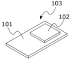
- FIG. 3 is a perspective view showing a substrate 103 with a solid electrolyte having a first substrate 101 and a solid electrolyte 102 arranged on the first substrate 101.
- the first substrate 101 is a member having a function of supporting the solid electrolyte 102 and has a sheet shape in FIG. 3, but its shape is not particularly limited as long as it can support the solid electrolyte 102.
- the material of the first substrate 101 is not particularly limited, but is preferably an insulator, and examples of the material of the first substrate include an organic material and an inorganic material. Examples of the organic material include paper and a polymer. Glass etc. are mentioned as an inorganic material.
- the thickness of the first substrate is not particularly limited and can be appropriately selected. However, from the viewpoint of easy handling, typically, the thickness is preferably 0.1 ⁇ m to 10 mm.
- the solid electrolyte 102 is brought into contact with the test object to capture microorganisms of the test object and at least one kind of biological particles selected from the group consisting of particles (eg, spores) derived from the microorganisms. It is a member.
- the test object is not particularly limited.
- a medium necessary for controlling disease in plants and a medium necessary for preventing infectious diseases caused by microorganisms in animals including humans can be used as test objects.
- the inspection target include plant organs (eg, leaves, stems, petals, roots, etc.), soil in the plant growth environment, and air (eg, open-field and / or house-field air). , And water (water for spraying, aerosol, etc.).
- test object examples include a medical device, and more specifically, a component of the medical device that touches a living mucous membrane of a subject during use.
- a medical device for example, in the case of an endoscope, an insertion portion (a distal end portion, a bending portion, a passive bending portion, a flexible tube portion, or the like) inserted into a subject, and an operation portion (angle knob, air supply) connected to the insertion portion / Water supply cylinder, air supply / water supply button, etc.), an endoscope connector (water supply pipe, auxiliary water supply base, etc.) connected to the end of a universal cord extending from the operation section, and a brush for cleaning these members And cleaning / disinfecting waste liquid.
- an endoscope connector water supply pipe, auxiliary water supply base, etc.
- the components and structure of the endoscope are known, but if necessary, refer to Japanese Patent Application Laid-Open No. 2018-130473.
- the method for bringing the solid electrolyte 102 into contact with the test object is not particularly limited, and may be appropriately selected according to the form of the test object.
- the solid electrolyte 102 is also a member serving as a medium for electrochemical measurement described later, and a known solid electrolyte can be used as a material thereof.
- a known solid electrolyte can be used as a material thereof.
- hydrogel is preferred as the solid electrolyte because of its excellent handleability. Examples of the hydrogel include an agar gel and a gelatin gel.
- the solid electrolyte is preferably one having high ion conductivity, and more specifically, one capable of moving ions (for example, hydrogen ions and sulfate ions) inside the solid electrolyte.
- the hydrogel may contain a sulfate or the like in that it has more excellent ion conductivity.
- the solid electrolyte may contain a substance serving as an electron source and / or an electron transfer substance for the purpose of assisting or promoting the electron transfer function of the biological particles to be detected.
- the substance serving as the electron source an organic compound is preferable, and examples thereof include glucose, acetic acid, and lactic acid.
- the electron mediator include riboflavin and the like.
- a protective sheet (not shown) may be further disposed on the solid electrolyte 102.
- the protective sheet When a protective sheet is placed on a solid electrolyte, the protective sheet is peeled off before use and used, so that the solid electrolyte can be kept in a clean state until use, and more accurate measurement results are easily obtained. .
- FIG. 4 is a schematic diagram illustrating a state in which the solid electrolyte is brought into contact with a plant organ.
- the solid electrolyte 102 is brought into contact with the leaf 401 of the plant 400.
- the method for bringing the solid electrolyte 102 into contact with the leaf 401 is not particularly limited, and the solid electrolyte 102 may be brought into contact with at least one portion of the surface of the leaf 401. With the above, at least a part of the biological particles existing on the leaf 401 is captured on the solid electrolyte 102.
- the solid electrolyte 102 is brought into contact with the leaf 401 of the plant 400.
- the solid electrolyte may be brought into contact with a desired organ, for example, stems, leaves, roots, petals, and the like. It may be brought into contact with any organ.
- the plant to be inspected in the measuring device according to the embodiment of the present invention is not particularly limited, and examples thereof include vegetables, grains, fruits, and algae.
- vegetables for example, perilla, strawberry, watermelon, melon, radish, carrot, burdock, potato, sweet potato, onion, asparagus, cabbage, lettuce, spinach, Chinese cabbage, tomato, eggplant, pumpkin, pepper, cucumber, myoga, cauliflower , Broccoli, edible chrysanthemum, ginger, turmeric and the like.
- cereals for example, corn, rice, wheat, barley, oat, rye, millet, millet, millet, sorghum (Takakibi, Kouryan, sorghum), soybean, adzuki bean, mung bean, kidney bean, peanut, peas, faba bean, lentil, koma bean , Buckwheat and buckwheat buckwheat.
- sorghum Teakakibi, Kouryan, sorghum
- soybean adzuki bean, mung bean, kidney bean, peanut, peas, faba bean, lentil, koma bean , Buckwheat and buckwheat buckwheat.
- fruits for example, orange, grapefruit, yuzu, daidai, kabos, sudachi, shikuwasa, lemon, lime, citron, nutsumikan, hassaku, hyuganatu, bellows, sweetie, yokan, mandarin orange, unshuikan, ponkan, kishu mandarin orange, kumquat , Karin, Chinese pear, Pear, Pear, Apple, American cherry, Apricot, Plum, Cherry, Plum, Peach, Almond, Ginkgo, Chestnut, Walnut, Pecan, Akebi, Fig, Oyster, Cassis, Raspberry, Kiwi, Gummy, Mulberry, cranberry, cowberry, pomegranate, currant, jujube, haskap, bilberry, grape, blackberry, blueberry, raspberry, olive, loquat, bayberry, and the like.
- algae examples include marine algae such as green algae, red algae, and blue-green algae; cyanobacteria, euglena, and the like.
- FIG. 5 is a perspective view of the biosensor 100 formed by joining the substrate 103 with a solid electrolyte and the substrate 108 with an electrode via a spacer 104.
- the two electrodes of the substrate with electrodes 108 and the solid electrolyte of the substrate 103 with solid electrolyte are in contact.
- the biosensor includes a first substrate, a substrate with a solid electrode having a solid electrolyte disposed on the first substrate, and a second substrate, and two electrodes disposed on the second substrate.
- a laminate in which a solid electrolyte and two or more electrodes are laminated so as to be in contact with each other.
- FIG. 6 is a plan view illustrating an example of the main body 600 included in the measuring device according to the embodiment of the present invention.
- the main body 600 has a housing 601, a display 602 disposed on the housing 601, an operation button 603, and a sensor insertion port 604, and is used by inserting the biosensor 100 into the sensor insertion port 604.
- the main body 600 includes a CPU (Central Processing Unit), a RAM (Random Access Memory), and a ROM required for predetermined operations (for example, application of a voltage and communication with the outside) of the measuring apparatus according to the embodiment of the present invention. It has a circuit board on which electronic components such as (Read Only Memory) are mounted.
- CPU Central Processing Unit
- RAM Random Access Memory
- ROM Read Only Memory
- the main body 600 is portable, but the main body according to the embodiment of the present invention is not limited to the above, and may be a stationary type.
- the display 602 displays a measurement procedure, a setting procedure, an operation procedure, an operation status, and the like.
- the display 602 is a display device such as a liquid crystal panel, a plasma display panel, and an electroluminescence panel.
- the plurality of operation buttons 603 are used to perform operations such as various settings (setting of measurement conditions, input of an ID of a sample, and the like), start of measurement, and end of measurement.
- the plurality of operation buttons 603 may be a contact-type touch panel. In that case, the display 602 and the operation buttons 603 may be integrated.
- FIG. 7 is a partially enlarged view around the sensor insertion port in a state where the biosensor 100 is inserted into the main body 600.
- FIG. 8 is a sectional view taken along the line AA 'in FIG.
- the electrode of the biosensor and the connector 801 are electrically connected.
- the inserted biosensor 100 is pressed by an electric cylinder (actuator) including a plate 802, a telescopic rod 803 connected to the plate 802, and a cylinder 804, so that the solid electrolyte 102 and the electrode come into close contact with each other.
- an electric cylinder actuator
- the measurement device has the electric cylinder therein, and the solid electrolyte and the electrode in the biosensor are pressed and adhered with a predetermined pressure, so that the measurement conditions are easily uniformed for each biosensor, As a result, the variation in the measurement result tends to be smaller.
- the measuring device may not have the electric cylinder.
- the biosensor may be one in which two substrates are closely bonded by using an actuator outside the device. For example, an operator may manually bond two substrates without using an actuator. It may be in a form to be performed.
- FIG. 9 shows a configuration of main electronic components housed in the housing of the measuring device 900.
- a control computer 918, a potentiostat 919 (corresponding to a voltage applying unit), and a power supply device 911 are arranged on a substrate 901 housed in the main body.
- the control computer 918 includes a processor such as a CPU (Central Processing Unit), a recording medium such as a RAM (Random Access Memory) and a ROM (Read Only Memory), and a communication unit in terms of hardware.
- a processor such as a CPU (Central Processing Unit)
- a recording medium such as a RAM (Random Access Memory) and a ROM (Read Only Memory)
- a communication unit in terms of hardware.
- the processor When the processor loads the program stored in the recording medium into the RAM and executes the program, the processor functions as a device including the output unit 910, the control unit 912, the calculation unit 913, and the detection unit 914.
- the control computer 918 may further include an auxiliary storage device such as a semiconductor memory (for example, a flash memory) and a hard disk.
- the control unit 912 controls the timing of voltage application to the biosensor 917, the applied voltage value, the driving of the electric cylinder, and the like.
- the power supply device 911 includes a battery 916, and supplies operation power to the control computer 918 and the potentiostat 919. Note that the power supply device 911 can be placed outside the housing.
- the potentiostat 919 can make the potential between the two electrodes constant or sweep the applied voltage, is controlled by the control unit 912, and is typically a biosensor 917 using the terminals CR and W. A predetermined voltage is applied between the two electrodes, the response current is measured, and the measurement result of the response current is sent to the detection unit 914.
- the computing unit 913 calculates and provides information for evaluating the risk of disease occurrence in plants by comparing the obtained current value with a reference value stored in advance in a storage device arranged on the substrate. I do.
- This reference value defines at least one factor selected from the group consisting of the presence or absence of biological particles, the growth state of microorganisms, and the presence or absence of pathogenicity of microorganisms, and a current value.
- FIG. 10 is a schematic diagram showing the relationship between the current value obtained from each of the sample D1 and the sample D2 and the voltage application time (measurement time) when a predetermined voltage is applied between the electrodes (constant potential measurement). It is a typical graph.
- the reference value in FIG. 10 is the magnitude of the current value at a predetermined measurement time, and indicates the presence or absence of a biological particle to be detected on the solid electrolyte (the detection target is selected by the distance between two electrodes).
- IC A which is determined in advance by machine learning or the like in relation to the expression status of pathogenicity.
- the detected current value at time t was I 1, arithmetic unit, this value is compared with a reference value IC A, in a plant which is an inspection object, predetermined Output that there is a possibility that the disease has occurred.
- the output content for example, it may be a value itself of the difference between I 1 and IC A, the difference value, and may be both of the information about the possibility of the occurrence of disease in plants.
- the value of I 1 and / or the difference between I 1 and IC A can be used as a marker for evaluating the risk of disease occurrence in plants.
- the reference value in FIG. 10 is the magnitude of the current value during a predetermined measurement time.
- the reference value in the measurement device according to the embodiment of the present invention is not limited to the above.
- the absolute value of the current value the rate of change of current (dI / dt, first-order differential value), the second order differential value (d 2 I / dt 2) , ( the time until the rise of the current value) the inflection point of the dI / dt, maximum current value It may be a value, a time until the current value reaches a maximum value, or the like.
- FIG. 11 is a schematic graph showing a magnitude of a current value with respect to a potential difference between the electrodes of the sample D3 and the sample D4 when a sweep voltage is applied between the electrodes.
- the maximum value I 3 of the detected current value to the sweep voltage, calculating unit this value is compared with a reference value IC B, it is inspected object
- An output indicating that there is a possibility that a predetermined disease has occurred in the plant is output.
- the output content for example, it may be a value itself of the difference between I 3 and IC B, the value of the difference, and may be both of the information about the possibility of the occurrence of disease in plants.
- the value of the difference between I 3 and / or I 3 and IC B are available as a risk evaluation marker diseases in plants.
- the reference value in FIG. 11 is the maximum value of the current obtained with respect to the sweep voltage
- the reference value in the measuring device according to the embodiment of the present invention is not limited to the above, and includes, for example, the number of peaks, And / or the width of a peak.
- the operation unit 913 stores the obtained operation result.
- the output unit 910 performs data communication with the display unit 915, and transmits to the display unit 915 the calculation result of the disease occurrence risk of the test object by the calculation unit 913.
- the display unit 915 displays, for example, a type of disease that may have occurred in the plant as the inspection target received from the output unit 910 and a calculation result of the progress thereof on a display screen in a predetermined format. Can be displayed.
- FIG. 12 shows a flow of the measurement processing by the control computer 918.
- the CPU control unit 912 of the control computer 918 controls the potentiostat 919 to apply a predetermined voltage between the two electrodes or apply a sweep voltage to adjust the response current.
- the measurement is started (Step S01).
- the detection of the attachment of the biosensor 917 to the measuring device may be used as the measurement start instruction.
- the control unit may control the electric cylinder to bring the solid electrolyte into contact with the electrode before starting the measurement.
- the potentiostat 919 measures the response current obtained by applying the voltage, and sends it to the detection unit 914 (step S02).
- the calculation unit 913 performs calculation processing based on the current value, and calculates the content of the biological particles to be detected in the solid electrolyte (not shown) of the biosensor 917 (step S03). For example, the calculation unit 913 of the control computer 918 calculates the risk of disease occurrence in the plant by comparing with the reference value by the method described above.
- the output unit 910 transmits the calculation result of the content of the biological particles to be detected to the display unit 915 through a communication link formed with the display unit 915 (step S04). Thereafter, the control unit 912 displays the content of the biological particles to be detected on the display unit, and ends the measurement.
- a solid electrolyte is brought into contact with a test object (typically, an organ of a plant), and microorganisms of the test object and at least one kind of biological particles selected from the group consisting of particles derived from the microorganisms are brought into contact therewith.
- a test object typically, an organ of a plant
- microorganisms of the test object and at least one kind of biological particles selected from the group consisting of particles derived from the microorganisms are brought into contact therewith.
- Step A Preparing a substrate with an electrode having a substrate and at least two electrodes disposed on the substrate, disposing the solid electrolyte after contact on the substrate with electrodes such that the solid electrolyte comes into contact with any of the electrodes, forming a biosensor;
- Step B A step of applying a voltage between the electrodes and measuring the obtained current value (step C); A current value, a reference value defining at least one factor selected from the group consisting of the presence or absence of biological particles, the current value stored in advance, and the growth state of the microorganism, and the presence or absence of the expression of pathogenicity of the microorganism; And a step (Step D) of obtaining information for evaluating the risk of the occurrence of a disease caused by microorganisms by comparing the above (Step D).
- Step A can be performed, for example, by bringing the substrate with a solid electrolyte described above into an environment where plants are growing. Further, by adjusting the shortest distance between the electrodes in the substrate with electrodes used in step B, target biological particles can be detected.
- the substrate with electrodes can be disposable, and a plurality of types of biological particles (derived from a plurality of microorganisms) can be detected by changing the shortest distance between the electrodes.
- Steps C and D are performed by inserting the formed biosensor into the main body described above and operating the operation buttons according to the instructions displayed on the display. It can be carried out as it is in a place with no special pretreatment and equipment operation, so even an operator without specialized knowledge can easily obtain information for evaluating the risk of disease occurrence. it can.
- the measurement device is in contact with a plant organ, and a solid electrolyte for capturing biological particles on at least the surface of the organ, A biosensor having two electrodes and a third electrode different from the two electrodes, wherein the solid electrolyte and the two electrodes and the third electrode are arranged to be in contact with each other; A voltage application unit for applying a voltage between the electrodes, A detector for measuring a current value flowing between the two electrodes when the voltage is applied; An arithmetic unit for providing information for determining the risk of disease occurrence in the plant by comparing the current value with a reference value defining a current value stored in advance and the risk of disease occurrence. And a measuring device comprising:
- the biosensor to be used has a substrate with electrodes having two electrodes and a third electrode different from the electrodes. That is, the biosensor is a three-electrode sensor.
- FIG. 13 is a perspective view of a substrate with electrodes included in the biosensor.
- the substrate with electrodes 1300 has a first electrode 106 and a second electrode 107 formed on the second substrate 105. These forms are similar to the biosensor described above.
- the substrate with electrodes 1300 has two third electrodes 1301 on the second substrate 105.
- the substrate with electrodes 1300 has two third electrodes 1301, but the biosensor included in the measuring device according to the present embodiment is not limited to the above, and may have one third electrode. Alternatively, it may have three or more third electrodes.
- the third electrode functions as a reference electrode when the biosensor is electrically connected to the measurement device.
- the measuring device having the biosensor having the reference electrode can measure the electrode potential, and has a more excellent effect of the present invention.
- a known reference electrode for an electrochemical measurement cell can be used, and for example, a silver / silver chloride electrode or the like can be used.
- the biosensor is formed by bringing the substrate with electrode 1300 into contact with the solid electrolyte.
- the region indicated by A in FIG. 13, that is, the first electrode, the second electrode, and the third electrode The solid electrolyte is placed in contact with all of the electrodes.
- the farmland management system in the farmland divided into a plurality of sections, the measuring device disposed for each section, by remote communication connection with the measuring device, caused by microorganisms
- a terminal that obtains information for evaluating the risk of disease occurrence in the test object from the measurement device, and the farmland management system, wherein the information for each section can be displayed on the terminal.
- This is a farmland management system.
- the farmland management system the information obtained from the measuring device arranged for each predetermined section, from the correspondence of the section where the measuring device is installed, the information for each section Are configured to be displayed on the remote control terminal. According to the farmland management system, information for evaluating the risk of disease occurring in the inspection target in each section can be obtained. This allows the operator to create a pesticide spraying plan for each section and determine the destruction of agricultural products for each section.
- a farmland management system according to an embodiment of the present invention will be described with reference to the drawings.
- FIG. 14 is a configuration diagram of the farmland management system according to the embodiment of the present invention.
- the farmland management system 1400 according to the embodiment of the present invention includes a measuring device 1403 installed in a farmland 1401 divided into a plurality of sections 1402, and a remote communication connection with each of the measuring devices 1403 (for example, short-range wireless communication). Communication) capable terminal 1404.
- each measuring device 1403 determines the risk of disease caused by microorganisms in the inspection object (typically in the air in each section) of the installed section by the method described above. Get information to evaluate.
- the biosensor in the measuring device may be replaced by the operator each time the measurement is performed, or the actuator mechanism outside the device may continuously or intermittently attach and detach the solid electrolyte and the electrode, continuously, or Alternatively, the inspection object may be intermittently acquired on the solid electrolyte and / or the electrode and automatically measured.
- the information obtained by each measuring device 1403 is collected by the terminal 1404 through a remote communication connection, and is displayed on the terminal 1404 as information for each partition based on the correspondence between the partition in which each measuring device is arranged and the above information.
- the terminal 1404 is a portable information terminal with a communication function including a touch panel display for input and output, but is not limited to the above.
- the operator can evaluate the risk of disease occurring in the inspection target caused by the microorganisms in each section, and determine the pesticide spraying plan (eg, the time and type of pesticide spraying) for each section. .
- the high risk section may be configured to automatically spray the pesticide.
- FIG. 15A is a schematic diagram illustrating an example of the structure of a tube (tube) that constitutes a flexible tube part of an insertion portion of an endoscope that is inserted into a subject as a constituent member of a medical device. is there.
- a tube 1500 illustrated in FIG. 15A includes a tube main body 1501 and a joint 1502.
- the material of the tube main body 1501 is, for example, fluorine resin, silicon rubber, or the like.
- the material of the joint 1502 is, for example, a metal such as stainless steel, a resin, or the like.
- the tube 1500 is cleaned with a cleaning liquid. After the washing, the solid electrolyte is brought into contact with the outer surface of the tube body 1501 and / or the joint 1502.
- a solid electrolyte may be brought into contact with the brush or the like.
- the solid electrolyte may be brought into contact with the waste liquid after washing, and in this case, the waste liquid may be subjected to a treatment such as concentration in advance, as necessary.
- the method for bringing the solid electrolyte into contact with the medium is not particularly limited, and the solid electrolyte may be brought into contact with at least one portion of the surface of the medium (the liquid level in the case of a liquid). By doing as described above, at least a part of the biological particles present in the medium is captured on the solid electrolyte.
- FIG. 15B is a schematic diagram illustrating another example of the structure of a tube that is a component of the endoscope.
- a tube 1510 illustrated in FIG. 15B includes a tube main body 1511 and a base 1512.
- the material of the tube main body 1511 is, for example, fluororesin, silicon rubber, or the like.
- the material of the joint portion 1512 is, for example, a metal such as stainless steel, a resin, or the like.
- at least a part of the biological particles existing in the medium is brought into contact with the medium by contacting the solid electrolyte with an arbitrary medium. Can be captured.
- S. oneidensis MR-1 As a biological particle to be detected, S. oneidensis MR-1 (hereinafter simply referred to as "MR-1") was used.
- BACKGROUND ART Iron-reducing bacteria represented by bacteria belonging to the genus Schwanella, such as S. oneidensis, are bacteria present in nature, and reproduce NAD + by extracellular electron transport (EET). It is known to do.
- EET extracellular electron transport
- These bacteria transfer electrons generated by the decomposition (metabolism) of electron donors (organic substances) in the cells into extracellular electron acceptors via electron transfer enzymes (cytochrome c) expressed in the outer cell membrane. (Electric current-producing bacteria) because of their ability to transmit to metals and the like.
- a culture solution containing MR-1 was smeared on one surface.
- This culture medium contains a synthetic medium containing 10 mM lactic acid, and MR-1 exhibits an electron transfer function by metabolizing lactic acid and organic substances contained in LB agar medium under anaerobic conditions. , A current is generated.
- a three-electrode type electrode configuration (working electrode: gold (diameter: 4 mm), counter electrode: gold, reference electrode: silver) is used.
- a commercially available screen-printed gold electrode manufactured by DropSens, Model number 220AT was used. It should be noted that the electrodes of the three-electrode biosensor used in this test example are not comb-shaped electrodes having a comb shape.
- the absorbance (OD 600 ) at a wavelength of 600 nm is 0 (control not containing MR-1), 0.01 (7.5 ⁇ 10 5 cells), 0.05 (3. Measurement was started using cells of 75 ⁇ 10 6 cells, 0.1 (7.5 ⁇ 10 6 cells), 0.4 (3 ⁇ 10 7 cells), and 0.8 (6 ⁇ 10 7 cells). The current value ( ⁇ A) was measured for 24 hours from the time when the voltage was applied to the electrode of the biosensor (the result is not shown).
- FIG. 16 is a graph showing the relationship between the concentration of MR-1 (OD 600 value) and the slope of the “time-current value” curve when the current value rises.
- FIG. 16 shows that the OD 600 value representing the concentration of MR-1 and the slope of the curve have a linear relationship.
- FIG. 18 shows the relationship between the concentration of MR-1 (the logarithm of the OD 600 value) and the time to reach the maximum value of the current value in the results shown in FIG. 17 (in the case of using the LB agar medium containing riboflavin).
- FIG. 18 Since the graph shown in FIG. 18 has a linear relationship, the current value measured by the measurement device according to the embodiment of the present invention may be correlated with an increase in the biological particles to be detected (growth behavior of microorganisms). It was suggested.
- FIG. 19 shows the results obtained in the case where the culture solution of MR-1 having an OD 600 value of 0.8 (6 ⁇ 10 7 cells) was used, as shown in FIG. It is a graph which shows the relationship between a potential (voltage value with respect to a standard hydrogen electrode (SHE)) and a measured current ([Delta] I, unit: [mu] A) at time points of 0.5 hours and 4.5 hours. As shown in FIG. 19, the curves obtained for the above three time points have high similarity, and no remarkable difference was observed.
- SHE standard hydrogen electrode
- the peaks indicated by the signs (X), (Y) and (Z) respectively indicate the following three modes from MR-1 captured by the solid electrolyte to the biosensor electrode. It is considered to indicate that electrons are being transmitted by: (X) an embodiment in which electron transfer from MR-1 to the electrode is mediated by riboflavin contained in the solid electrolyte; (Y) a mode in which riboflavin contained in a solid electrolyte is adsorbed on a membrane protein on the surface of MR-1 to promote electron transfer from MR-1 to an electrode; (Z) A mode in which electrons are transferred from MR-1 to the electrode without passing through riboflavin contained in the solid electrolyte.
- the present invention can detect microorganisms having an electron transfer function, and is expected to be applied to various uses including the above-described plants and medical devices.
- biosensor 101 first substrate 101: on first substrate 102: solid electrolyte 103: substrate with solid electrolyte 104: spacer 105: second substrate 106: first electrode 107: second electrode 108: substrate with electrode 213:
- Arithmetic unit 400 Plant 401: Leaf 600: Body 601: Housing 602: Display 603: Operation button 604: Sensor insertion port 801: Connector 802: Plate 803: Telescopic rod 804: Cylinder 900: Measuring device 901: Substrate 910: Output Unit 911: power supply device 912: control unit 913: calculation unit 914: detection unit 915: display unit 915: display unit 916: battery 917: biosensor 918: control computer 919: potentiostat (voltage application unit) 1300: substrate with electrode 1301: third electrode 1400: farmland management system 1401: farmland 1402: section 1403: measuring device 1404: terminals 1500, 1510: tubes 1501, 1511: tube body 1502: joint 1512
Landscapes
- Chemical & Material Sciences (AREA)
- Life Sciences & Earth Sciences (AREA)
- Health & Medical Sciences (AREA)
- Organic Chemistry (AREA)
- Immunology (AREA)
- General Health & Medical Sciences (AREA)
- Physics & Mathematics (AREA)
- Analytical Chemistry (AREA)
- Biochemistry (AREA)
- Molecular Biology (AREA)
- Wood Science & Technology (AREA)
- Proteomics, Peptides & Aminoacids (AREA)
- Zoology (AREA)
- Engineering & Computer Science (AREA)
- Chemical Kinetics & Catalysis (AREA)
- Electrochemistry (AREA)
- Pathology (AREA)
- General Physics & Mathematics (AREA)
- General Engineering & Computer Science (AREA)
- Genetics & Genomics (AREA)
- Microbiology (AREA)
- Biotechnology (AREA)
- Bioinformatics & Cheminformatics (AREA)
- Biophysics (AREA)
- Toxicology (AREA)
- Epidemiology (AREA)
- Public Health (AREA)
- Apparatus Associated With Microorganisms And Enzymes (AREA)
- Investigating Or Analyzing Materials By The Use Of Electric Means (AREA)
- Measuring Or Testing Involving Enzymes Or Micro-Organisms (AREA)
Abstract
Le dispositif de mesure selon un mode de réalisation de la présente invention comprend : une unité d'application de tension pour appliquer une tension entre des électrodes d'un biocapteur, ledit biocapteur comprenant un électrolyte solide et au moins deux électrodes et l'électrolyte solide étant disposé de manière à être mis en contact avec les électrodes ; une unité de détection pour mesurer la valeur d'un courant électrique circulant entre les électrodes lorsque la tension est appliquée ; et une unité de calcul pour fournir des informations engendrées par un micro-organisme par comparaison de la valeur du courant électrique avec une valeur standard qui définit une valeur de courant électrique stockée à l'avance et au moins un facteur choisi dans le groupe constitué par la présence/l'absence de particules biologiques, l'état de croissance du micro-organisme, et la présence/l'absence d'expression de la pathogénicité du micro-organisme.
Priority Applications (3)
| Application Number | Priority Date | Filing Date | Title |
|---|---|---|---|
| JP2020540199A JP7246752B2 (ja) | 2018-08-29 | 2019-08-06 | 測定装置、及び、評価方法 |
| US17/268,715 US20210318261A1 (en) | 2018-08-29 | 2019-08-06 | Measurement device and evaluation method |
| EP19853919.9A EP3845629B1 (fr) | 2018-08-29 | 2019-08-06 | Dispositif de mesure et procédé d'évaluation |
Applications Claiming Priority (2)
| Application Number | Priority Date | Filing Date | Title |
|---|---|---|---|
| JP2018-160199 | 2018-08-29 | ||
| JP2018160199 | 2018-08-29 |
Publications (1)
| Publication Number | Publication Date |
|---|---|
| WO2020044978A1 true WO2020044978A1 (fr) | 2020-03-05 |
Family
ID=69644865
Family Applications (1)
| Application Number | Title | Priority Date | Filing Date |
|---|---|---|---|
| PCT/JP2019/030791 Ceased WO2020044978A1 (fr) | 2018-08-29 | 2019-08-06 | Dispositif de mesure et procédé d'évaluation |
Country Status (4)
| Country | Link |
|---|---|
| US (1) | US20210318261A1 (fr) |
| EP (1) | EP3845629B1 (fr) |
| JP (1) | JP7246752B2 (fr) |
| WO (1) | WO2020044978A1 (fr) |
Cited By (3)
| Publication number | Priority date | Publication date | Assignee | Title |
|---|---|---|---|---|
| RU2769994C1 (ru) * | 2021-02-25 | 2022-04-12 | Федеральное государственное бюджетное учреждение науки Сибирский федеральный научный центр агробиотехнологий Российской академии наук (СФНЦА РАН) | Способ мониторинга динамики развития грибной болезни земляники садовой |
| WO2022264901A1 (fr) * | 2021-06-16 | 2022-12-22 | 国立研究開発法人物質・材料研究機構 | Dispositif de traitement de la péri-implantite et procédé d'ajustement de l'activité d'un biofilm |
| JP2023055058A (ja) * | 2021-10-05 | 2023-04-17 | 国立大学法人山形大学 | 植物の内部成分の電気化学的分析方法および分光学的分析方法、水系溶媒または水系電解液を媒質とするハイドロゲル、ならびに電気化学的分析キットおよび分光学的分析キット |
Families Citing this family (2)
| Publication number | Priority date | Publication date | Assignee | Title |
|---|---|---|---|---|
| US20240418694A1 (en) * | 2023-06-14 | 2024-12-19 | Electronics And Telecommunications Research Institute | Electrical plant monitoring device and operation method thereof |
| GB2634255A (en) * | 2023-10-03 | 2025-04-09 | Univ Durham | An electrochemical system for detecting bacterial growth in a duct |
Citations (7)
| Publication number | Priority date | Publication date | Assignee | Title |
|---|---|---|---|---|
| JP2012071028A (ja) | 2010-09-29 | 2012-04-12 | Fujifilm Corp | 内視鏡洗浄管理システム及び内視鏡洗浄管理方法 |
| JP2015150224A (ja) | 2014-02-14 | 2015-08-24 | 株式会社モリタ製作所 | 内視鏡洗浄消毒装置およびホルダ部材 |
| JP2015177914A (ja) | 2014-03-19 | 2015-10-08 | テルモ株式会社 | 洗浄装置 |
| JP2016220651A (ja) | 2015-06-02 | 2016-12-28 | 国立大学法人徳島大学 | イチゴうどんこ病菌の検出方法および検出用プライマー |
| WO2017006122A1 (fr) * | 2015-07-08 | 2017-01-12 | The University Court Of The University Of Edinburgh | Biocapteur |
| JP2017202128A (ja) | 2016-05-12 | 2017-11-16 | オリンパス株式会社 | 内視鏡洗浄用ブラシ |
| JP2018130473A (ja) | 2017-02-17 | 2018-08-23 | 富士フイルム株式会社 | 内視鏡用洗浄治具 |
Family Cites Families (10)
| Publication number | Priority date | Publication date | Assignee | Title |
|---|---|---|---|---|
| US20020090649A1 (en) * | 1999-12-15 | 2002-07-11 | Tony Chan | High density column and row addressable electrode arrays |
| DE10259819B4 (de) * | 2002-12-19 | 2006-07-13 | Siemens Ag | Verfahren zur PCR-Amplifikation und Detektion von Nucleotidsequenzen |
| US20120077206A1 (en) * | 2003-07-12 | 2012-03-29 | Accelr8 Technology Corporation | Rapid Microbial Detection and Antimicrobial Susceptibility Testing |
| DE102006016326B4 (de) * | 2006-04-06 | 2012-07-19 | Fraunhofer-Gesellschaft zur Förderung der angewandten Forschung e.V. | Vorrichtung und Verfahren zur Schnellmessung eines mikrobiologischen Zustands einer Probe |
| US8399262B2 (en) * | 2011-03-23 | 2013-03-19 | Darrel A. Mazzari | Biosensor |
| KR102148747B1 (ko) * | 2012-08-09 | 2020-08-27 | 더 보드 오브 트러스티스 오브 더 리랜드 스탠포드 쥬니어 유니버시티 | 현미경적 분석을 위한 생물학적 표본을 준비하기 위한 방법과 조성물 |
| JP2014110780A (ja) * | 2012-10-29 | 2014-06-19 | Panasonic Healthcare Co Ltd | 微生物数測定装置および微生物数測定方法 |
| US9746441B2 (en) * | 2013-05-13 | 2017-08-29 | Sony Corporation | Sensor, sensor kit and method for detecting an analyte |
| JP6487919B2 (ja) * | 2013-08-29 | 2019-03-20 | ノースイースタン ユニバーシティ | 病原菌用マトリクスによって強化された電気化学検出器 |
| CA3050062A1 (fr) * | 2016-01-14 | 2017-07-20 | Roswell Biotechnologies, Inc. | Capteurs moleculaires et procedes associes |
-
2019
- 2019-08-06 WO PCT/JP2019/030791 patent/WO2020044978A1/fr not_active Ceased
- 2019-08-06 EP EP19853919.9A patent/EP3845629B1/fr active Active
- 2019-08-06 US US17/268,715 patent/US20210318261A1/en not_active Abandoned
- 2019-08-06 JP JP2020540199A patent/JP7246752B2/ja active Active
Patent Citations (7)
| Publication number | Priority date | Publication date | Assignee | Title |
|---|---|---|---|---|
| JP2012071028A (ja) | 2010-09-29 | 2012-04-12 | Fujifilm Corp | 内視鏡洗浄管理システム及び内視鏡洗浄管理方法 |
| JP2015150224A (ja) | 2014-02-14 | 2015-08-24 | 株式会社モリタ製作所 | 内視鏡洗浄消毒装置およびホルダ部材 |
| JP2015177914A (ja) | 2014-03-19 | 2015-10-08 | テルモ株式会社 | 洗浄装置 |
| JP2016220651A (ja) | 2015-06-02 | 2016-12-28 | 国立大学法人徳島大学 | イチゴうどんこ病菌の検出方法および検出用プライマー |
| WO2017006122A1 (fr) * | 2015-07-08 | 2017-01-12 | The University Court Of The University Of Edinburgh | Biocapteur |
| JP2017202128A (ja) | 2016-05-12 | 2017-11-16 | オリンパス株式会社 | 内視鏡洗浄用ブラシ |
| JP2018130473A (ja) | 2017-02-17 | 2018-08-23 | 富士フイルム株式会社 | 内視鏡用洗浄治具 |
Non-Patent Citations (2)
| Title |
|---|
| MASSAD-IVANIR, NAAMA ET AL.: "Construction and ] Characterization of Porous Si02/Hydrogel Hybrids as Optical Biosensors for Rapid Detection of Bacteria", ADV. FUNCT. MATER., vol. 20, 2010, pages 2269 - 2277, XP001556720, DOI: 10.1002/adfm.201000406 * |
| VIGUES, N. ET AL.: "Electro-addressable conductive alginate hydrogel for bacterial trapping and general toxicity determination", ANAL. CHIM. ACTA., vol. 1036, 26 June 2018 (2018-06-26), pages 115 - 120, XP055695954 * |
Cited By (6)
| Publication number | Priority date | Publication date | Assignee | Title |
|---|---|---|---|---|
| RU2769994C1 (ru) * | 2021-02-25 | 2022-04-12 | Федеральное государственное бюджетное учреждение науки Сибирский федеральный научный центр агробиотехнологий Российской академии наук (СФНЦА РАН) | Способ мониторинга динамики развития грибной болезни земляники садовой |
| WO2022264901A1 (fr) * | 2021-06-16 | 2022-12-22 | 国立研究開発法人物質・材料研究機構 | Dispositif de traitement de la péri-implantite et procédé d'ajustement de l'activité d'un biofilm |
| JPWO2022264901A1 (fr) * | 2021-06-16 | 2022-12-22 | ||
| JP7804354B2 (ja) | 2021-06-16 | 2026-01-22 | 国立研究開発法人物質・材料研究機構 | インプラント周囲炎治療装置、及び、バイオフィルムの活性調整方法 |
| JP2023055058A (ja) * | 2021-10-05 | 2023-04-17 | 国立大学法人山形大学 | 植物の内部成分の電気化学的分析方法および分光学的分析方法、水系溶媒または水系電解液を媒質とするハイドロゲル、ならびに電気化学的分析キットおよび分光学的分析キット |
| JP7770012B2 (ja) | 2021-10-05 | 2025-11-14 | 国立大学法人山形大学 | 植物の内部成分の電気化学的分析方法および分光学的分析方法、水系溶媒または水系電解液を媒質とするハイドロゲル、ならびに電気化学的分析キットおよび分光学的分析キット |
Also Published As
| Publication number | Publication date |
|---|---|
| EP3845629A1 (fr) | 2021-07-07 |
| US20210318261A1 (en) | 2021-10-14 |
| JP7246752B2 (ja) | 2023-03-28 |
| EP3845629B1 (fr) | 2023-10-25 |
| EP3845629A4 (fr) | 2022-08-10 |
| JPWO2020044978A1 (ja) | 2021-08-26 |
Similar Documents
| Publication | Publication Date | Title |
|---|---|---|
| JP7246752B2 (ja) | 測定装置、及び、評価方法 | |
| Mishra et al. | Wearable flexible and stretchable glove biosensor for on-site detection of organophosphorus chemical threats | |
| Mishra et al. | Detection of vapor-phase organophosphate threats using wearable conformable integrated epidermal and textile wireless biosensor systems | |
| EP3227671B1 (fr) | Dispositif et procédé de détection de contaminant | |
| US11226306B2 (en) | Microbial sensor system for monitoring and imaging of an environment | |
| Ge et al. | Halloysite nanotube/black phosphorene nanohybrid modified screen-printed carbon electrode as an ultra-portable electrochemical sensing platform for smartphone-capable detection of maleic hydrazide with machine learning assistance | |
| CN203772786U (zh) | 芯片式叉指阵列电极阻抗传感器 | |
| KR20150124980A (ko) | 샘플의 균수를 평가하는 진단 장치 | |
| JP2017529874A (ja) | 迅速な細菌感染診断のための診断システムとプロセス | |
| CN107643333B (zh) | 一种检测水体毒性的双信号生物电化学方法 | |
| Shah et al. | Biosensing platform on a flexible substrate | |
| Ravindra et al. | Advances in the manufacturing, types, and applications of biosensors | |
| JP5007905B2 (ja) | 分子鋳型を有するポリマーを備えたセンサー | |
| GB2560251A (en) | Diamond based electrochemical sensors | |
| Patel et al. | Part II: Impedance-based DNA biosensor for detection of isolated strains of phytopathogen Ralstonia solanacearum | |
| US20180057785A1 (en) | Electrochemical sensors for cell culture monitoring | |
| Radhi et al. | Electrochemical study of Pb (II) in present of each ascorbic acid, glucose, urea and uric acid using blood medium as an electrolyte | |
| Tchieno et al. | Adsorptive stripping voltammetric determination of mangiferin using an activated chitosan modified carbon paste electrode | |
| Oliver et al. | An impedimetric sensor for monitoring the growth of Staphylococcus epidermidis | |
| Kashyap et al. | A plug-and-play type field-deployable bio-agent-free salicylic acid sensing system | |
| EP3001193A1 (fr) | Systeme pour la caracterisation de l'eau pure et extra-pure | |
| CN108181365B (zh) | 活体检测水杨酸的微型比率型传感器及其构建方法与应用 | |
| Kim et al. | A pH sensing pipette for cross-contamination prevention in industrial fermentation | |
| Hosu et al. | Electrochemical (Bio) Sensors Based on Nanotechnologies for the Detection of Important Biomolecules in Plants and Plant-Related Samples: The Future of Smart and Precision Agriculture | |
| JP7770012B2 (ja) | 植物の内部成分の電気化学的分析方法および分光学的分析方法、水系溶媒または水系電解液を媒質とするハイドロゲル、ならびに電気化学的分析キットおよび分光学的分析キット |
Legal Events
| Date | Code | Title | Description |
|---|---|---|---|
| 121 | Ep: the epo has been informed by wipo that ep was designated in this application |
Ref document number: 19853919 Country of ref document: EP Kind code of ref document: A1 |
|
| ENP | Entry into the national phase |
Ref document number: 2020540199 Country of ref document: JP Kind code of ref document: A |
|
| NENP | Non-entry into the national phase |
Ref country code: DE |
|
| ENP | Entry into the national phase |
Ref document number: 2019853919 Country of ref document: EP Effective date: 20210329 |