WO2020045089A1 - Élément composite et procédé pour le fabriquer - Google Patents
Élément composite et procédé pour le fabriquer Download PDFInfo
- Publication number
- WO2020045089A1 WO2020045089A1 PCT/JP2019/031896 JP2019031896W WO2020045089A1 WO 2020045089 A1 WO2020045089 A1 WO 2020045089A1 JP 2019031896 W JP2019031896 W JP 2019031896W WO 2020045089 A1 WO2020045089 A1 WO 2020045089A1
- Authority
- WO
- WIPO (PCT)
- Prior art keywords
- composite member
- coating layer
- intermediate layer
- less
- base material
- Prior art date
- Legal status (The legal status is an assumption and is not a legal conclusion. Google has not performed a legal analysis and makes no representation as to the accuracy of the status listed.)
- Ceased
Links
Images

Classifications
-
- C—CHEMISTRY; METALLURGY
- C23—COATING METALLIC MATERIAL; COATING MATERIAL WITH METALLIC MATERIAL; CHEMICAL SURFACE TREATMENT; DIFFUSION TREATMENT OF METALLIC MATERIAL; COATING BY VACUUM EVAPORATION, BY SPUTTERING, BY ION IMPLANTATION OR BY CHEMICAL VAPOUR DEPOSITION, IN GENERAL; INHIBITING CORROSION OF METALLIC MATERIAL OR INCRUSTATION IN GENERAL
- C23C—COATING METALLIC MATERIAL; COATING MATERIAL WITH METALLIC MATERIAL; SURFACE TREATMENT OF METALLIC MATERIAL BY DIFFUSION INTO THE SURFACE, BY CHEMICAL CONVERSION OR SUBSTITUTION; COATING BY VACUUM EVAPORATION, BY SPUTTERING, BY ION IMPLANTATION OR BY CHEMICAL VAPOUR DEPOSITION, IN GENERAL
- C23C18/00—Chemical coating by decomposition of either liquid compounds or solutions of the coating forming compounds, without leaving reaction products of surface material in the coating; Contact plating
- C23C18/16—Chemical coating by decomposition of either liquid compounds or solutions of the coating forming compounds, without leaving reaction products of surface material in the coating; Contact plating by reduction or substitution, e.g. electroless plating
- C23C18/18—Pretreatment of the material to be coated
-
- C—CHEMISTRY; METALLURGY
- C23—COATING METALLIC MATERIAL; COATING MATERIAL WITH METALLIC MATERIAL; CHEMICAL SURFACE TREATMENT; DIFFUSION TREATMENT OF METALLIC MATERIAL; COATING BY VACUUM EVAPORATION, BY SPUTTERING, BY ION IMPLANTATION OR BY CHEMICAL VAPOUR DEPOSITION, IN GENERAL; INHIBITING CORROSION OF METALLIC MATERIAL OR INCRUSTATION IN GENERAL
- C23C—COATING METALLIC MATERIAL; COATING MATERIAL WITH METALLIC MATERIAL; SURFACE TREATMENT OF METALLIC MATERIAL BY DIFFUSION INTO THE SURFACE, BY CHEMICAL CONVERSION OR SUBSTITUTION; COATING BY VACUUM EVAPORATION, BY SPUTTERING, BY ION IMPLANTATION OR BY CHEMICAL VAPOUR DEPOSITION, IN GENERAL
- C23C18/00—Chemical coating by decomposition of either liquid compounds or solutions of the coating forming compounds, without leaving reaction products of surface material in the coating; Contact plating
- C23C18/16—Chemical coating by decomposition of either liquid compounds or solutions of the coating forming compounds, without leaving reaction products of surface material in the coating; Contact plating by reduction or substitution, e.g. electroless plating
- C23C18/31—Coating with metals
- C23C18/32—Coating with nickel, cobalt or mixtures thereof with phosphorus or boron
- C23C18/34—Coating with nickel, cobalt or mixtures thereof with phosphorus or boron using reducing agents
-
- C—CHEMISTRY; METALLURGY
- C23—COATING METALLIC MATERIAL; COATING MATERIAL WITH METALLIC MATERIAL; CHEMICAL SURFACE TREATMENT; DIFFUSION TREATMENT OF METALLIC MATERIAL; COATING BY VACUUM EVAPORATION, BY SPUTTERING, BY ION IMPLANTATION OR BY CHEMICAL VAPOUR DEPOSITION, IN GENERAL; INHIBITING CORROSION OF METALLIC MATERIAL OR INCRUSTATION IN GENERAL
- C23C—COATING METALLIC MATERIAL; COATING MATERIAL WITH METALLIC MATERIAL; SURFACE TREATMENT OF METALLIC MATERIAL BY DIFFUSION INTO THE SURFACE, BY CHEMICAL CONVERSION OR SUBSTITUTION; COATING BY VACUUM EVAPORATION, BY SPUTTERING, BY ION IMPLANTATION OR BY CHEMICAL VAPOUR DEPOSITION, IN GENERAL
- C23C28/00—Coating for obtaining at least two superposed coatings either by methods not provided for in a single one of groups C23C2/00 - C23C26/00 or by combinations of methods provided for in subclasses C23C and C25C or C25D
-
- C—CHEMISTRY; METALLURGY
- C25—ELECTROLYTIC OR ELECTROPHORETIC PROCESSES; APPARATUS THEREFOR
- C25D—PROCESSES FOR THE ELECTROLYTIC OR ELECTROPHORETIC PRODUCTION OF COATINGS; ELECTROFORMING; APPARATUS THEREFOR
- C25D5/00—Electroplating characterised by the process; Pretreatment or after-treatment of workpieces
- C25D5/34—Pretreatment of metallic surfaces to be electroplated
- C25D5/42—Pretreatment of metallic surfaces to be electroplated of light metals
- C25D5/44—Aluminium
-
- C—CHEMISTRY; METALLURGY
- C25—ELECTROLYTIC OR ELECTROPHORETIC PROCESSES; APPARATUS THEREFOR
- C25D—PROCESSES FOR THE ELECTROLYTIC OR ELECTROPHORETIC PRODUCTION OF COATINGS; ELECTROFORMING; APPARATUS THEREFOR
- C25D7/00—Electroplating characterised by the article coated
- C25D7/06—Wires; Strips; Foils
Definitions
- the present disclosure relates to a composite member and a method for manufacturing the same.
- This application claims the priority based on Japanese Patent Application No. 2018-160691 filed on Aug. 29, 2018, and incorporates all the contents described in these Japanese applications.
- Patent Literature 1 discloses that double zincate treatment is performed using two specific and different plating baths.
- Patent Document 2 discloses a method of forming an anodic oxide film on the surface of aluminum and then dissolving and removing a part of the film.
- Patent Document 3 discloses a method of forming an anodic oxide film having a concavo-convex structure on the surface of aluminum and electrolytically depositing particulate nickel.
- JP 2008-190034 A JP-A-61-84395 JP-A-11-302854
- One aspect of the present disclosure is: A substrate made of pure aluminum or an aluminum alloy, An intermediate layer provided on the surface of the base material, A coating layer provided on the surface of the intermediate layer, The intermediate layer includes aluminum oxide, and has a plurality of protrusions protruding from the base material side, The height H of the protrusion is not less than 10 nm and not more than 100 nm,
- the cover layer relates to a composite member including nickel.
- Another aspect of the present disclosure includes: A substrate made of pure aluminum or an aluminum alloy, An intermediate layer provided on the surface of the base material, A coating layer provided on the surface of the intermediate layer, The intermediate layer includes an aluminum oxide,
- the coating layer is a composite member containing nickel and having a thickness of 2.2 mm or less, After heating the composite member at 500 ° C. for 10 minutes, when the composite member cooled to room temperature is bent, a curvature radius R at which peeling of the coating layer occurs is equal to or less than the thickness D1 of the base material. About.
- Yet another aspect of the present disclosure includes: A step of preparing a substrate composed of pure aluminum or an aluminum alloy, Forming an intermediate layer containing aluminum oxide on the surface of the base material, Forming a coating layer containing nickel on the surface of the intermediate layer, The step of forming the intermediate layer, Forming a thin film of aluminum oxide having a thickness of 2 nm or more and 10 nm or less on the surface of the base material; A step of subjecting the substrate on which the thin film of the aluminum oxide is formed to electroless nickel plating using a plating bath having a pH of 8 or more and less than 10 at 25 ° C. About the method.
- FIG. 1 is a cross-sectional view schematically illustrating a composite member according to an embodiment of the present disclosure.
- FIG. 2 is an enlarged sectional view schematically showing a part of the composite member shown in FIG.
- a composite member includes a base made of pure aluminum or an aluminum alloy, an intermediate layer provided on a surface of the base, and a surface provided on the surface of the intermediate layer.
- the aluminum oxide is arranged in a fine projection shape. Therefore, the composite member has high adhesion between the base material and the coating layer. Further, since the intermediate layer is formed thin, thermal stress generated between the base material and the intermediate layer is small. Therefore, even if the composite member is bent after heating, peeling of the coating layer is suppressed.
- the pitch between the adjacent protrusions may be 1 nm or more and 100 nm or less. Since the fine projections are arranged at a fine pitch, the adhesion between the base material and the coating layer is further improved.
- the thickness D1 of the base material may be 0.01 mm or more and 2 mm or less.
- the thickness D1 is 0.01 mm or more, high bending resistance is obtained. Since the intermediate layer of the present embodiment is thin, deterioration of the substrate surface when the intermediate layer is formed is suppressed. Therefore, if the base material has a thickness of 0.01 mm or more, the strength of the base material can be sufficiently maintained. Further, even with a relatively thick substrate of 2 mm or less, peeling due to bending is easily suppressed.
- the thickness D2 of the coating layer may be 0.1 ⁇ m or more and 20 ⁇ m or less.
- the thickness D2 is 0.1 ⁇ m or more, the effect of the coating layer is increased. Even with a relatively thick coating layer of 20 ⁇ m or less, the adhesion between the substrate and the coating layer is easily ensured.
- the ratio (D2 / H) of the thickness D2 of the coating layer to the height H of the protrusion may be 50 or more and 1000 or less. Even in the case where the projections are low, the adhesion between the base material and the coating layer can be sufficiently ensured.
- the base material may be a wire. This is because a base material that is often used after being bent, such as a wire, has a high necessity to suppress peeling of the coating layer after the heat treatment.
- a composite member includes a base made of pure aluminum or an aluminum alloy, an intermediate layer provided on a surface of the base, and a surface provided on the intermediate layer.
- the radius of curvature R at which the coating layer peels off is not more than the thickness D1 of the base material. Since such a composite member has high heat resistance, peeling of the coating layer is suppressed even if bending processing is performed after heating.
- a method of manufacturing a composite member includes a step of preparing a base made of pure aluminum or an aluminum alloy, and an intermediate layer containing aluminum oxide on the surface of the base. And a step of forming a coating layer containing nickel on the surface of the intermediate layer, wherein the step of forming the intermediate layer includes forming an aluminum layer having a thickness of 2 nm or more and 10 nm or less on the surface of the base material. Forming an oxide thin film and subjecting the base material on which the aluminum oxide thin film is formed to electroless nickel plating using a plating bath having a pH of 8 or more and less than 10 at 25 ° C. And a step. Thereby, a composite member having high heat resistance can be easily obtained.
- the double zincate treatment utilizes an oxidation-reduction reaction (precipitation (reduction) of zinc and dissolution (oxidation) of aluminum).
- precipitation (reduction) of zinc and dissolution (oxidation) of aluminum.
- the dissolution rate of aluminum tends to increase, and aluminum may be partially eroded. The eroded portion is likely to be a starting point of fracture of aluminum as a base material.
- the aluminum oxide film needs to have a thickness of 200 nm or more. Since aluminum oxide has poor ductility, when the composite member having such a thick aluminum oxide film is bent, the aluminum oxide film tends to crack. In addition, a large thermal stress is likely to be applied between the aluminum and the aluminum oxide film during the heat treatment. This also tends to cause cracks in the aluminum oxide film. On the other hand, when the aluminum oxide film is thinned, the anchor effect is weakened, and the nickel film is easily peeled.
- a nickel film (nickel coating layer) having excellent heat resistance is formed on a base material containing aluminum by using an aluminum oxide film having a predetermined structure.
- the heat resistance refers to the difficulty of peeling of the nickel coating layer after the heat treatment.
- the composite member according to the present embodiment includes a base member made of pure aluminum or an aluminum alloy (hereinafter, sometimes referred to as an Al base member), an intermediate layer provided on the surface of the base member, and an intermediate layer.
- the intermediate layer contains aluminum oxide and has a plurality of protrusions protruding from the base material side.
- the height H of the projection is not less than 10 nm and not more than 100 nm.
- the coating layer contains nickel.
- the intermediate layer is very thin, at least in this respect, different from the anodized film. Therefore, thermal stress generated between the base material and the intermediate layer is small. Furthermore, since the aluminum oxide is arranged in the shape of minute projections, an anchor effect is exhibited. Therefore, even if the composite member is subjected to bending after heating, peeling of the coating layer is suppressed.
- Another composite member according to the present embodiment includes a base made of pure aluminum or an aluminum alloy, an intermediate layer provided on the surface of the base, and a coating layer provided on the surface of the intermediate layer.
- the intermediate layer contains aluminum oxide
- the coating layer contains nickel
- the thickness of the composite member is 2.2 mm or less.
- a radius of curvature R at which peeling of the coating layer occurs (hereinafter, referred to as a critical radius of curvature R) is the thickness of the substrate. D1 or less. That is, the composite member according to this embodiment has a small critical radius of curvature R even after the heat treatment, and is excellent in heat resistance.
- the critical radius of curvature R may be 0.9 times or less the thickness D1 of the substrate.
- the method of bending the composite member when obtaining the critical radius of curvature R includes: (a) a method of winding the composite member around a wire, or (b) a method of performing the bending test according to JIS H8504 on the Al base. Select according to. Specifically, in the case of a composite member that can be bent by a method of winding around a wire, such as a composite member in which the Al base is a wire (a linear member), the method of (a) is used. adopt. On the other hand, in the case of a composite member, such as a composite member in which the Al base is a plate material, which is substantially difficult to bend by a method of winding around a wire, the method (b) is adopted.
- a composite member heated at 500 ° C. for 10 minutes and cooled to room temperature is prepared.
- the composite member is bent by winding it around a wire having a diameter of 20 times, 10 times, 5 times, 4 times, 3 times, 2 times, and 1 times the thickness D1 of the base material.
- the composite member is wound around the wire three times.
- the entire appearance of the composite member is observed with a stereoscopic microscope, and the presence or absence of peeling of the Ni coating layer is confirmed. Five samples are prepared, and the diameter of the wire when one or more of the samples show peeling is defined as a critical radius of curvature R.
- a composite member heated at 500 ° C. for 10 minutes and cooled to room temperature is prepared.
- one end of the composite member is fixed, and the other end is bent at a bending radius of 20 times, 10 times, 5 times, 4 times, 3 times the thickness D1 of the base material.
- Each of them is pressed and bent against a twofold or onefold backing plate.
- the entire appearance of the composite member is observed with a stereoscopic microscope, and the presence or absence of peeling of the Ni coating layer is confirmed.
- Five samples are prepared, and a radius of curvature when one or more of the samples show peeling is defined as a critical radius of curvature R.
- the room temperature is 25 ° C.
- the critical radius of curvature R can be equal to or less than the thickness D1 of the substrate even when the composite member is heated in a range of 300 ° C. or more and 660 ° C. or less for 10 minutes and then cooled to room temperature.
- the heating temperature may or may not be constant.
- peeling of the Ni coating layer is suppressed.
- FIG. 1 is a cross-sectional view schematically illustrating the composite member according to the present embodiment.
- the composite member 10 of the present embodiment includes an Al base 11, an aluminum oxide-containing intermediate layer (hereinafter, sometimes referred to as an oxide intermediate layer) 13 provided on the surface of the Al base 11, and oxidation.
- the thickness D of the composite member is not particularly limited.
- the thickness D of the composite member may be 0.015 mm or more and 2.2 mm or less, 0.12 mm or more and 2 mm or less, or 0.12 mm or more and 1.7 mm or less. When the thickness D is in this range, the strength is easily maintained and the bending process is easy.
- the composite member of this embodiment is excellent in heat resistance. Therefore, it is suitable for use in heat treatment or use in a high-temperature environment. Such applications include, for example, lead wires of capacitors or batteries mounted on electronic devices, bumps connecting electronic devices, and automotive parts.
- the coating layer of the composite member may be further coated with another metal coating layer.
- the conductivity of the composite member can be comparable to the conductivity of the Al base. Since the protrusions of the aluminum oxide as the insulator are minute, a decrease in the conductivity of the Al base is suppressed.
- the ratio (C2 / C1) of the conductivity C2 of the composite member to the conductivity C1 of the Al base may be, for example, 80% or more, and may be 85% or more.
- C2 / C1 is, for example, 100% or less, and may be 99.9% or less.
- the Al base is made of pure aluminum or an aluminum alloy.
- the Al base material may be an extension material or a casting.
- the type of metal other than aluminum contained in the aluminum alloy is not particularly limited, and may be appropriately selected depending on the use and the like.
- the aluminum alloy includes, in addition to aluminum, for example, at least one selected from the group consisting of copper, iron, chromium, manganese, magnesium, silicon, zinc, and lithium.
- the content of metals other than aluminum contained in the aluminum alloy is not particularly limited, and may be appropriately selected depending on the use and the like.
- the shape of the Al base is not particularly limited, and may be a plate, a rod, a wire (a linear Al base), a tube, a foil, or any other desired shape.
- the adhesion between the Al substrate and the coating layer is high, and thus the peeling of the coating layer can be suppressed. .
- the thickness D1 of the Al base is not particularly limited.
- the thickness D1 may be 0.01 mm or more and 2 mm or less, or may be 0.1 mm or more and 1.5 mm or less.
- the thickness D1 is 0.01 mm or more, high bending resistance is obtained.
- the oxide intermediate layer is thin, the deterioration of the surface of the Al base when the oxide intermediate layer is formed is suppressed. Therefore, if the Al base has a thickness of 0.01 mm or more, it is easy to maintain the strength of the Al base. Moreover, even for a relatively thick composite member of 2 mm or less, peeling due to bending can be sufficiently suppressed.
- the thickness D1 of the rod-shaped or wire base material is the diameter or the maximum diameter
- the thickness D1 of the tubular base material is ⁇ of the difference between the inner diameter and the outer diameter.
- the Al base may be subjected to a cleaning treatment prior to the formation of the oxide intermediate layer.
- the cleaning process includes, for example, at least one of degreasing, etching, and smut removal.
- Degreasing is a treatment for removing oil on the surface of an Al base, and for example, an aqueous solution called an alkaline degreasing agent is used.
- the etching is a process for removing a film of aluminum oxide formed on the surface of the Al base material, and usually uses a strong alkaline aqueous solution containing sodium hydroxide or the like.
- the smut removal is a process of removing smut (fine powdery black unnecessary material) generated at the time of etching. For example, an acidic aqueous solution containing nitric acid or the like is used.
- the intermediate layer containing aluminum oxide (oxide intermediate layer) is provided on the surface of the Al base.
- the oxide intermediate layer has a plurality of protrusions containing aluminum oxide.
- the projection protrudes from the substrate side toward the Ni coating layer side.
- the height H of the protrusion is not less than 10 nm and not more than 100 nm. That is, the oxide intermediate layer has a fine uneven structure formed of aluminum oxide. Due to the anchor effect of the uneven structure, the adhesion between the Al base and the Ni coating layer is improved. Further, since the uneven structure is minute, thermal stress generated between the Al base and the oxide intermediate layer during the heat treatment is small. Therefore, even if bending is performed after heating, cracks are less likely to occur in the oxide intermediate layer, and peeling of the Ni coating layer is suppressed.
- the height H of the protrusion may be 15 nm or more, 20 nm or more, or 25 nm or more.
- the height H of the protrusion may be 80 nm or less, 75 nm or less, or 50 nm or less. When the height H of the projection is in this range, the thermal stress can be reduced while exhibiting a high anchoring effect.
- the height H of the projection is an average value of the distance from the surface of the Al base to the top of the projection.
- the height H of the projection is calculated from the cross-sectional image of the composite member.
- the cross-sectional image is taken with a transmission electron microscope (TEM).
- the composite member is cut in the thickness direction, and a cross section is photographed using a TEM.
- the photographing visual field is in a range including five protrusions of aluminum oxide.
- the positions of oxygen atoms and nickel atoms are confirmed by element mapping, and the oxide intermediate layer and the Ni coating layer are specified.
- the outer edge of the oxide intermediate layer is determined from the element mapping and the TEM image.
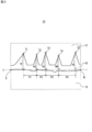
- FIG. 2 is an enlarged sectional view schematically showing a part of the composite member shown in FIG.
- the composite member 10 includes an Al base material 11, a Ni coating layer 12, and an oxide intermediate layer 13 interposed therebetween.
- the outer edge of the oxide intermediate layer 13 is shown by a solid line.
- the oxide intermediate layer 13 has five protrusions each having a top portion T1 to T5.
- L be a straight line connecting the ends A and B of the interface between the Al base 11 and the oxide intermediate layer 13 in the width direction of the TEM image.
- a perpendicular is drawn from the top T1 toward the straight line L, and the length of a line segment connecting the intersection of the perpendicular and the straight line L and the top T1 is defined as the height H1 of the projection having the top T1.
- the heights H2 to H5 of the other protrusions are obtained in the same manner.
- the average value of the heights H1 to H5 is defined as the height H of the projection.
- the height H of the protrusion may be sufficiently smaller than the Ni coating layer.
- the ratio (D2 / H) of the thickness D2 of the Ni coating layer to the height H of the protrusion may be 50 or more and 1000 or less, 70 or more and 500 or less, or 70 or more and 300 or less. And may be 100 or more and 300 or less. Even if the projections are low, the adhesion between the Al base and the Ni coating layer can be ensured.
- the pitch P between adjacent protrusions is not particularly limited.
- the pitch P may be 1 nm or more, 10 nm or more, or 20 nm or more.
- the pitch P may be 100 nm or less, 80 nm or less, or 50 nm or less. When the pitch P is in such a small range, the adhesion between the Al base and the Ni coating layer is further improved.
- Pitch P is an average value of the distance between the tops of adjacent protrusions. Like the height H, the pitch P is calculated from a TEM image of a cross section of the composite member cut in the thickness direction. In FIG. 2, a pitch P1 is defined as a distance between a perpendicular drawn from the top T1 toward the straight line L and a perpendicular drawn from the adjacent top T2 toward the straight line L.
- the pitches P2 to P4 are similarly obtained for the other protrusions.
- the average value of the pitches P1 to P4 is referred to as a pitch P.
- the oxide intermediate layer is formed, for example, by subjecting an Al base to electroless nickel plating.
- the electroless nickel plating process is performed on an Al base having a thin aluminum oxide film (hereinafter, referred to as an oxide thin film).
- the thickness of the oxide thin film may be smaller than the height H of the protrusion in the obtained composite member. Details of the electroless nickel plating and the oxide thin film will be described later.
- the Ni coating layer is provided on the surface of the intermediate layer.
- the Ni coating layer covers the surface of the substrate via the intermediate layer.
- the Ni coating layer contains nickel.
- the surface of the intermediate layer refers to a surface of the intermediate layer opposite to the Al substrate side.
- the thickness D2 of the Ni coating layer is not particularly limited.
- the thickness D2 may be, for example, 0.1 ⁇ m or more and 20 ⁇ m or less, or may be 0.5 ⁇ m or more and 10 ⁇ m or less. According to the present embodiment, even in the case of having a relatively thick Ni coating layer, the adhesion between the Al base and the Ni coating layer can be ensured.
- the thickness D2 is a distance from the surface of the Al base to the outer surface of the Ni coating layer, and is calculated from a TEM image of a cross section of the composite member cut in the thickness direction, similarly to the height H of the protrusion. Can be. In this case, the thickness at any five points is calculated, and the average value of these is set as the thickness D2.
- the Ni coating layer is formed by, for example, plating.
- the Ni coating layer may be formed by electroless nickel plating, or may be formed by electrolytic nickel plating.
- the Ni coating layer is preferably formed by electrolytic nickel plating in that the composite member is easily bent.
- the Al substrate to be plated has an oxide intermediate layer. However, since the oxide intermediate layer is thin, an electrolytic plating process can be employed. The plating process will be described later.
- the composite member according to this embodiment includes, for example, (I) a step of preparing an Al base, (II) a step of forming an oxide intermediate layer on the surface of the Al base, and (III) an oxide intermediate layer. Forming a Ni coating layer on the surface of the substrate.
- (IIb) forming an oxide thin film Applying a plating bath having a pH of 8 or more and less than 10 at 25 ° C. to the Al base material thus obtained by electroless nickel plating.
- the oxide thin film is obtained, for example, by performing degreasing, etching, and smut removal as a cleaning treatment on an Al base material.
- the oxide thin film formed on the surface of the Al base material after the removal of the smut is preferable in that it is dense.
- the thickness D3 of the oxide thin film may be 2 nm or more and 7 nm or less.
- the thickness D3 of the oxide thin film is measured by, for example, elemental analysis in the depth direction by X-ray photoelectron spectroscopy (XPS).
- the interface between the Al base and nickel is also oxidized, and a thin aluminum oxide film may be formed between the Al base and the Ni coating layer.
- the degree of dissolution and growth of the aluminum oxide film can be controlled by the plating conditions.
- an oxide intermediate layer having projections is formed, and nickel is disposed between the projections. This nickel constitutes a part of the Ni coating layer.
- the pH of the plating bath is changed from a weakly alkaline range to an alkaline range at room temperature.
- the pH of the plating bath at 25 ° C. is set to 8 or more and less than 10.
- the pH of the plating bath at 25 ° C. may be 8 or more and 9 or less. Accordingly, minute projections containing aluminum oxide and having a height H of 10 nm or more and 100 nm or less can be formed as the oxide intermediate layer.
- the temperature of the plating bath during the treatment may be, for example, 20 ° C or higher and 100 ° C or lower.
- the duration of the plating process may be appropriately set according to the height H of the projection to be formed and the temperature of the plating bath.
- the plating time may be, for example, 1 minute or more and 20 minutes or less, or 5 minutes or more and 15 minutes or less.
- the plating bath used in the electroless nickel plating treatment contains a nickel compound which is a source of nickel ions.
- the nickel compound include nickel sulfate, nickel chloride, nickel nitrate and the like.
- the plating bath of the electroless nickel plating treatment contains a nickel compound, a reducing agent, a complexing agent (chelating agent), a pH buffer, a brightener, a surfactant and the like. Additives other than these may be included. These compounds are appropriately added to the bath so as to maintain a predetermined concentration.
- the concentration of each compound is not particularly limited, and may be added at a conventionally known concentration.
- the nickel compound may be added at a concentration of 0.1 g / L or more and 50 g / L or less.
- the complexing agent may be added at a concentration of 1 g / L or more and 50 g / L or less.
- the reducing agent is a compound that reduces nickel ions, and examples thereof include sodium hypophosphite, a boron compound, and a hydrazine compound.
- the complexing agent is a compound that forms a complex with a metal ion in the bath and stabilizes the complex.
- the complexing agent is not particularly limited, and may be appropriately selected according to the type of the metal salt.
- Examples of the complexing agent include ammonium salts such as sulfuric acid, phosphoric acid, and hydrochloric acid, sulfamic acid, glycine, ethylenediamine, ethylenediaminetetraacetic acid, and organic carboxylic acids (gluconic acid, propionic acid, and the like).
- the pH buffer is a compound that prevents precipitation of metal ions, and examples thereof include boric acid, acetic acid, and citric acid.
- the brightener is a compound for smoothing the surface of the electrodeposition layer, and examples thereof include saccharin sodium, sodium naphthalenedisulfonic acid, sodium sulfate, and butynediol.
- the surfactant include sodium dodecyl sulfate and polyoxyethylene alkyl ether.
- Ni coating layer is formed on the surface of the oxide intermediate layer by plating.
- the Ni coating layer may be formed by electroless nickel plating, or may be formed by electrolytic nickel plating.
- the plating bath as described above is used for the electroless nickel plating.
- the pH at room temperature is not particularly limited.
- the plating bath used for the electrolytic nickel plating treatment is not particularly limited, and a conventionally known plating bath can be used.
- Typical electrolytic nickel plating baths include a watt bath mainly composed of nickel sulfate, nickel chloride and boric acid, a sulfamic acid bath mainly composed of nickel sulfamate and boric acid, and a nickel chloride and hydrochloric acid principally. Wood baths, black baths containing nickel sulfate, nickel ammonium sulfate, zinc sulfate, and sodium thiocyanate as main components are exemplified.
- the conditions for the electrolytic nickel plating are not particularly limited. Current density, for example, 0.1 A / dm 2 or more and 20A / dm 2 or less.
- the temperature of the plating bath is, for example, 20 ° C. or more and 70 ° C. or less.
- the time of the plating treatment may be appropriately set according to the desired thickness of the plating film.
- the obtained composite member may be subjected to a heat treatment.
- the Ni coating layer obtained according to this embodiment is more difficult to peel off by the heat treatment.
- the heating temperature is not particularly limited, but may be, for example, 300 ° C. or more and 660 ° C. or less.
- another metal coating layer (for example, a tin plating layer) may be formed on the surface of the Ni coating layer.
- Example 1 (1) Preparation of Al base material An aluminum wire (A1070) having a diameter (D1) of 0.5 mm was prepared.
- the wire was subjected to degreasing, etching and smut removal.
- An oxide thin film having a thickness D3 of 3 nm to 6 nm was formed on the entire surface of the wire.
- the thickness of the oxide thin film was measured by elemental analysis in the depth direction by XPS.
- the wire was immersed in a plating bath containing nickel sulfate hexahydrate 25 g / L and glycine 30 g / L at 60 ° C. for 2 minutes to form an oxide intermediate layer.
- the pH at 25 ° C. of the plating bath was 8.0.
- the wire on which the oxide intermediate layer was formed was nickel-plated using a Watt bath to obtain a composite member X1 having a diameter (D) of 506 ⁇ m.
- the thickness D2 of the Ni coating layer was 3 ⁇ m.
- the height H of the protrusions in the oxide intermediate layer of the obtained composite member X1 was 20 nm, and the pitch P between the protrusions was 17 nm.
- the outer edge of the oxide intermediate layer was determined by specifying the position of an oxygen atom by elemental mapping using TEM.
- Adhesion evaluation 2 Separately, after heating the composite member X1 at 500 ° C. for 10 minutes, it was cooled to room temperature. Next, one end of the composite member X1 is fixed, and the other end has a diameter of 10 mm (20 times D1), 5 mm (10 times), 2.5 mm (5 times), 2 mm (4 times). 3 times), 1.5 mm (3 times), 1 mm (2 times), and 0.5 mm SUS wire. In this state, the appearance was observed with a stereoscopic microscope, and the presence or absence of peeling of the Ni coating layer was confirmed. The diameter of the SUS wire corresponds to the radius of curvature of the composite member X1.
- Table 1 shows the diameter (critical radius of curvature R) of the SUS wire rod in which peeling of the Ni coating layer was confirmed for the first time. Five specimens were prepared, and the diameter of the SUS wire rod when one or more of the specimens showed separation was defined as a critical radius of curvature R.
- Example 2 In the step of forming the oxide intermediate layer, a composite member X2 having a diameter (D) of 506 ⁇ m was prepared and evaluated in the same manner as in Example 1 except that the treatment time was set to 10 minutes. Table 1 shows the results.
- the height H of the protrusions in the oxide intermediate layer was 40 nm, and the pitch P between the protrusions was 17 nm.
- Example 3 In the step of forming the oxide intermediate layer, a composite member X3 having a diameter (D) of 506 ⁇ m was prepared and evaluated in the same manner as in Example 1 except that the pH at 25 ° C. of the plating bath was 9.0. . Table 1 shows the results. The height H of the protrusions in the oxide intermediate layer was 15 nm, and the pitch P between the protrusions was 35 nm.
- Example 4 In the step of forming the oxide intermediate layer, except that the pH at 25 ° C. of the plating bath was set to 9.0 and the treatment time was set to 10 minutes, the process was performed in the same manner as in Example 1 except that the plating bath had a diameter (D) of 506 ⁇ m.
- a composite member X4 was prepared and evaluated. Table 1 shows the results.
- the height H of the protrusions in the oxide intermediate layer was 25 nm, and the pitch P between the protrusions was 35 nm.
- Example 2 In place of the step of forming the oxide intermediate layer, the wire was subjected to degreasing, etching, and smut removal, and then subjected to an anodic oxidation treatment I shown below and a removal treatment to remove a part of the formed anodic oxide film. Except for this, a composite member Y2 having a diameter (D) of 510 ⁇ m was prepared and evaluated in the same manner as in Example 1. Table 1 shows the results.
- the anodic oxidation treatment I was performed using titanium as a counter electrode in a bath having a sulfuric acid concentration of 15 g / 100 ml and a bath temperature of 28 ° C. under the conditions of an AC voltage of 15 V for 20 minutes.
- the removal treatment was performed in a bath having a phosphoric acid concentration of 10 g / 100 ml and a bath temperature of 26 ° C. for 4 minutes at a DC voltage of 5 V.
- the composite material having a diameter (D) of 506 ⁇ m was prepared in the same manner as in Example 1 except that the wire was degreased and etched, and then subjected to the following anodic oxidation treatment II.
- a member Y3 was prepared and evaluated. Table 1 shows the results.
- the anodizing treatment II was performed using titanium as a counter electrode in a bath of 13.4% by mass of phosphoric acid, 100 g / L of nickel carbonate, and a bath temperature of 24 ° C. for 5 minutes at an AC voltage of 7.5 V.
- protrusions including a plurality of aluminum oxides having a height of 200 nm and a pitch of 300 nm were formed between the wire and the Ni coating layer. It had been.
- a composite member Y4 having a diameter (D) of 506 ⁇ m was prepared and evaluated in the same manner as in Example 1 except that the pH at 25 ° C. of the plating bath was 10.0. . Table 1 shows the results. When a cross section of the obtained composite member Y4 was confirmed by a TEM image, no protrusion containing aluminum oxide was formed.
- Example 5 In the step of forming the oxide intermediate layer, except that the pH at 25 ° C. of the plating bath was set to 10.0 and the treatment time was set to 10 minutes, the diameter (D) of 506 ⁇ m was set in the same manner as in Example 1. A composite member Y5 was prepared and evaluated. Table 1 shows the results. When a cross section of the obtained composite member Y5 was confirmed by a TEM image, no protrusion containing aluminum oxide was formed.
- each of the composite members X1, X2, X3, and X4 has a smaller radius of curvature R than the diameter D1.
- the adhesion evaluation 1 on the Ni coating layer of the composite member Y1 was confirmed to be because Kirkendall voids resulting from the double zincate treatment were formed by the heat treatment.
- the adhesion evaluation 2 the Ni coating layer of the composite member Y1 was peeled in all cases. That is, the critical radius of curvature R is at least 20 times the diameter D1.
- the Ni coating layer of the composite member Y2 was peeled off. That is, the critical radius of curvature R is at least five times the diameter D1.
Landscapes
- Chemical & Material Sciences (AREA)
- Chemical Kinetics & Catalysis (AREA)
- Engineering & Computer Science (AREA)
- Materials Engineering (AREA)
- Metallurgy (AREA)
- Organic Chemistry (AREA)
- Mechanical Engineering (AREA)
- General Chemical & Material Sciences (AREA)
- Electrochemistry (AREA)
- Other Surface Treatments For Metallic Materials (AREA)
- Chemically Coating (AREA)
- Electroplating Methods And Accessories (AREA)
Abstract
L'invention concerne un élément composite comprenant un matériau de base constitué d'aluminium pur ou d'un alliage d' aluminium, une couche intermédiaire située sur la surface du matériau de base, et une couche de revêtement située sur la surface de la couche intermédiaire, la couche intermédiaire comprenant de l'oxyde d'aluminium et ayant une pluralité de projections dépassant depuis le côté du matériau de base, la hauteur H des projetions étant comprise entre 10 nm et 100 nm, et la couche de revêtement comprenant du nickel.
Priority Applications (1)
| Application Number | Priority Date | Filing Date | Title |
|---|---|---|---|
| JP2020539328A JPWO2020045089A1 (ja) | 2018-08-29 | 2019-08-14 | 複合部材およびその製造方法 |
Applications Claiming Priority (2)
| Application Number | Priority Date | Filing Date | Title |
|---|---|---|---|
| JP2018-160691 | 2018-08-29 | ||
| JP2018160691 | 2018-08-29 |
Publications (1)
| Publication Number | Publication Date |
|---|---|
| WO2020045089A1 true WO2020045089A1 (fr) | 2020-03-05 |
Family
ID=69644996
Family Applications (1)
| Application Number | Title | Priority Date | Filing Date |
|---|---|---|---|
| PCT/JP2019/031896 Ceased WO2020045089A1 (fr) | 2018-08-29 | 2019-08-14 | Élément composite et procédé pour le fabriquer |
Country Status (2)
| Country | Link |
|---|---|
| JP (1) | JPWO2020045089A1 (fr) |
| WO (1) | WO2020045089A1 (fr) |
Cited By (1)
| Publication number | Priority date | Publication date | Assignee | Title |
|---|---|---|---|---|
| CN112281187A (zh) * | 2020-11-06 | 2021-01-29 | 金川集团股份有限公司 | 一种制备电解镍用复合添加剂及其制备方法 |
Citations (2)
| Publication number | Priority date | Publication date | Assignee | Title |
|---|---|---|---|---|
| JPH0728072A (ja) * | 1993-07-15 | 1995-01-31 | Fujitsu Ltd | 積層電極の製造方法 |
| WO2018124116A1 (fr) * | 2016-12-27 | 2018-07-05 | 古河電気工業株式会社 | Matériau de traitement de surface et son procédé de fabrication, article fabriqué à l'aide du matériau de traitement de surface |
-
2019
- 2019-08-14 JP JP2020539328A patent/JPWO2020045089A1/ja active Pending
- 2019-08-14 WO PCT/JP2019/031896 patent/WO2020045089A1/fr not_active Ceased
Patent Citations (2)
| Publication number | Priority date | Publication date | Assignee | Title |
|---|---|---|---|---|
| JPH0728072A (ja) * | 1993-07-15 | 1995-01-31 | Fujitsu Ltd | 積層電極の製造方法 |
| WO2018124116A1 (fr) * | 2016-12-27 | 2018-07-05 | 古河電気工業株式会社 | Matériau de traitement de surface et son procédé de fabrication, article fabriqué à l'aide du matériau de traitement de surface |
Non-Patent Citations (1)
| Title |
|---|
| HONMA, HIDEO ET AL.: "Direct Circuit Formation Method on Aluminum Substrate by Electroless Nickel Plating", JOURNAL OF THE SURFACE FINISHING SOCIETY OF JAPAN, vol. 44, no. 12, 1993, pages 1084 - 1088, XP055690465 * |
Cited By (1)
| Publication number | Priority date | Publication date | Assignee | Title |
|---|---|---|---|---|
| CN112281187A (zh) * | 2020-11-06 | 2021-01-29 | 金川集团股份有限公司 | 一种制备电解镍用复合添加剂及其制备方法 |
Also Published As
| Publication number | Publication date |
|---|---|
| JPWO2020045089A1 (ja) | 2021-08-10 |
Similar Documents
| Publication | Publication Date | Title |
|---|---|---|
| WO2014207975A1 (fr) | Procédé de production d'un matériau plaqué, et matériau plaqué | |
| JP6665387B2 (ja) | 銀めっき部材及びその製造方法 | |
| WO2020045089A1 (fr) | Élément composite et procédé pour le fabriquer | |
| JP6651852B2 (ja) | 銀めっき部材及びその製造方法 | |
| JP6268408B2 (ja) | めっき材の製造方法及びめっき材 | |
| WO2020079904A1 (fr) | Matériau conducteur électrique, article moulé et composant électronique | |
| JP6086531B2 (ja) | 銀めっき材 | |
| JP3180197B2 (ja) | アルミニウム及びアルミニウム合金の表面処理法 | |
| CN115066514B (zh) | 金属材料及金属材料的制造方法 | |
| JPWO2019022188A1 (ja) | 錫めっき付銅端子材及び端子並びに電線端末部構造 | |
| JP4736084B2 (ja) | マグネシウム又はマグネシウム合金からなる製品の製造方法 | |
| JP6029202B2 (ja) | アルミニウムまたはアルミニウム合金材への純鉄の電気めっき方法 | |
| WO2020079905A1 (fr) | Matériau électroconducteur, article moulé et composant électronique | |
| JP2017014589A (ja) | 銀めっき材およびその製造方法 | |
| JP2024077764A (ja) | 銀被覆材の製造方法、銀被覆材および通電部品 | |
| US10629917B2 (en) | Separator for fuel cells, fuel cell, fuel cell stack, and method of manufacturing separator for fuel cells | |
| JPH0649685A (ja) | 鉄被覆複合材の製造方法 | |
| US20240344202A1 (en) | Wire and method for manufacturing wire | |
| JP2011174131A (ja) | めっき浴、めっき方法、めっき膜、放熱板 | |
| JP6978287B2 (ja) | めっき材 | |
| JP2017014588A (ja) | 銀めっき材およびその製造方法 | |
| JP5978439B2 (ja) | 導電部材 | |
| JP6274556B2 (ja) | 電解めっき方法 | |
| JP5076088B2 (ja) | Snめっき銅基板、Snめっき銅基板の製造方法、およびこれを用いたリードフレームおよびコネクタ端子 | |
| JP2003059361A (ja) | エナメル線用塗装ダイおよびその製造方法 |
Legal Events
| Date | Code | Title | Description |
|---|---|---|---|
| 121 | Ep: the epo has been informed by wipo that ep was designated in this application |
Ref document number: 19856149 Country of ref document: EP Kind code of ref document: A1 |
|
| ENP | Entry into the national phase |
Ref document number: 2020539328 Country of ref document: JP Kind code of ref document: A |
|
| NENP | Non-entry into the national phase |
Ref country code: DE |
|
| 122 | Ep: pct application non-entry in european phase |
Ref document number: 19856149 Country of ref document: EP Kind code of ref document: A1 |