WO2020045385A1 - Dispositif de purification du sang - Google Patents
Dispositif de purification du sang Download PDFInfo
- Publication number
- WO2020045385A1 WO2020045385A1 PCT/JP2019/033425 JP2019033425W WO2020045385A1 WO 2020045385 A1 WO2020045385 A1 WO 2020045385A1 JP 2019033425 W JP2019033425 W JP 2019033425W WO 2020045385 A1 WO2020045385 A1 WO 2020045385A1
- Authority
- WO
- WIPO (PCT)
- Prior art keywords
- cassette
- blood purification
- main body
- water removal
- attached
- Prior art date
- Legal status (The legal status is an assumption and is not a legal conclusion. Google has not performed a legal analysis and makes no representation as to the accuracy of the status listed.)
- Ceased
Links
Images







Classifications
-
- A—HUMAN NECESSITIES
- A61—MEDICAL OR VETERINARY SCIENCE; HYGIENE
- A61M—DEVICES FOR INTRODUCING MEDIA INTO, OR ONTO, THE BODY; DEVICES FOR TRANSDUCING BODY MEDIA OR FOR TAKING MEDIA FROM THE BODY; DEVICES FOR PRODUCING OR ENDING SLEEP OR STUPOR
- A61M1/00—Suction or pumping devices for medical purposes; Devices for carrying-off, for treatment of, or for carrying-over, body-liquids; Drainage systems
- A61M1/34—Filtering material out of the blood by passing it through a membrane, i.e. hemofiltration or diafiltration
- A61M1/3403—Regulation parameters
- A61M1/341—Regulation parameters by measuring the filtrate rate or volume
-
- A—HUMAN NECESSITIES
- A61—MEDICAL OR VETERINARY SCIENCE; HYGIENE
- A61M—DEVICES FOR INTRODUCING MEDIA INTO, OR ONTO, THE BODY; DEVICES FOR TRANSDUCING BODY MEDIA OR FOR TAKING MEDIA FROM THE BODY; DEVICES FOR PRODUCING OR ENDING SLEEP OR STUPOR
- A61M1/00—Suction or pumping devices for medical purposes; Devices for carrying-off, for treatment of, or for carrying-over, body-liquids; Drainage systems
- A61M1/14—Dialysis systems; Artificial kidneys; Blood oxygenators ; Reciprocating systems for treatment of body fluids, e.g. single needle systems for hemofiltration or pheresis
- A61M1/16—Dialysis systems; Artificial kidneys; Blood oxygenators ; Reciprocating systems for treatment of body fluids, e.g. single needle systems for hemofiltration or pheresis with membranes
- A61M1/1621—Constructional aspects thereof
- A61M1/1629—Constructional aspects thereof with integral heat exchanger
-
- A—HUMAN NECESSITIES
- A61—MEDICAL OR VETERINARY SCIENCE; HYGIENE
- A61M—DEVICES FOR INTRODUCING MEDIA INTO, OR ONTO, THE BODY; DEVICES FOR TRANSDUCING BODY MEDIA OR FOR TAKING MEDIA FROM THE BODY; DEVICES FOR PRODUCING OR ENDING SLEEP OR STUPOR
- A61M1/00—Suction or pumping devices for medical purposes; Devices for carrying-off, for treatment of, or for carrying-over, body-liquids; Drainage systems
- A61M1/14—Dialysis systems; Artificial kidneys; Blood oxygenators ; Reciprocating systems for treatment of body fluids, e.g. single needle systems for hemofiltration or pheresis
- A61M1/15—Dialysis systems; Artificial kidneys; Blood oxygenators ; Reciprocating systems for treatment of body fluids, e.g. single needle systems for hemofiltration or pheresis with a cassette forming partially or totally the flow circuit for the treating fluid, e.g. the dialysate fluid circuit or the treating gas circuit
- A61M1/152—Details related to the interface between cassette and machine
-
- A—HUMAN NECESSITIES
- A61—MEDICAL OR VETERINARY SCIENCE; HYGIENE
- A61M—DEVICES FOR INTRODUCING MEDIA INTO, OR ONTO, THE BODY; DEVICES FOR TRANSDUCING BODY MEDIA OR FOR TAKING MEDIA FROM THE BODY; DEVICES FOR PRODUCING OR ENDING SLEEP OR STUPOR
- A61M1/00—Suction or pumping devices for medical purposes; Devices for carrying-off, for treatment of, or for carrying-over, body-liquids; Drainage systems
- A61M1/14—Dialysis systems; Artificial kidneys; Blood oxygenators ; Reciprocating systems for treatment of body fluids, e.g. single needle systems for hemofiltration or pheresis
- A61M1/15—Dialysis systems; Artificial kidneys; Blood oxygenators ; Reciprocating systems for treatment of body fluids, e.g. single needle systems for hemofiltration or pheresis with a cassette forming partially or totally the flow circuit for the treating fluid, e.g. the dialysate fluid circuit or the treating gas circuit
- A61M1/153—Dialysis systems; Artificial kidneys; Blood oxygenators ; Reciprocating systems for treatment of body fluids, e.g. single needle systems for hemofiltration or pheresis with a cassette forming partially or totally the flow circuit for the treating fluid, e.g. the dialysate fluid circuit or the treating gas circuit the cassette being adapted for heating or cooling the treating fluid, e.g. the dialysate or the treating gas
-
- A—HUMAN NECESSITIES
- A61—MEDICAL OR VETERINARY SCIENCE; HYGIENE
- A61M—DEVICES FOR INTRODUCING MEDIA INTO, OR ONTO, THE BODY; DEVICES FOR TRANSDUCING BODY MEDIA OR FOR TAKING MEDIA FROM THE BODY; DEVICES FOR PRODUCING OR ENDING SLEEP OR STUPOR
- A61M1/00—Suction or pumping devices for medical purposes; Devices for carrying-off, for treatment of, or for carrying-over, body-liquids; Drainage systems
- A61M1/14—Dialysis systems; Artificial kidneys; Blood oxygenators ; Reciprocating systems for treatment of body fluids, e.g. single needle systems for hemofiltration or pheresis
- A61M1/15—Dialysis systems; Artificial kidneys; Blood oxygenators ; Reciprocating systems for treatment of body fluids, e.g. single needle systems for hemofiltration or pheresis with a cassette forming partially or totally the flow circuit for the treating fluid, e.g. the dialysate fluid circuit or the treating gas circuit
- A61M1/155—Dialysis systems; Artificial kidneys; Blood oxygenators ; Reciprocating systems for treatment of body fluids, e.g. single needle systems for hemofiltration or pheresis with a cassette forming partially or totally the flow circuit for the treating fluid, e.g. the dialysate fluid circuit or the treating gas circuit with treatment-fluid pumping means or components thereof
-
- A—HUMAN NECESSITIES
- A61—MEDICAL OR VETERINARY SCIENCE; HYGIENE
- A61M—DEVICES FOR INTRODUCING MEDIA INTO, OR ONTO, THE BODY; DEVICES FOR TRANSDUCING BODY MEDIA OR FOR TAKING MEDIA FROM THE BODY; DEVICES FOR PRODUCING OR ENDING SLEEP OR STUPOR
- A61M1/00—Suction or pumping devices for medical purposes; Devices for carrying-off, for treatment of, or for carrying-over, body-liquids; Drainage systems
- A61M1/14—Dialysis systems; Artificial kidneys; Blood oxygenators ; Reciprocating systems for treatment of body fluids, e.g. single needle systems for hemofiltration or pheresis
- A61M1/15—Dialysis systems; Artificial kidneys; Blood oxygenators ; Reciprocating systems for treatment of body fluids, e.g. single needle systems for hemofiltration or pheresis with a cassette forming partially or totally the flow circuit for the treating fluid, e.g. the dialysate fluid circuit or the treating gas circuit
- A61M1/156—Constructional details of the cassette, e.g. specific details on material or shape
- A61M1/1562—Details of incorporated reservoirs
-
- A—HUMAN NECESSITIES
- A61—MEDICAL OR VETERINARY SCIENCE; HYGIENE
- A61M—DEVICES FOR INTRODUCING MEDIA INTO, OR ONTO, THE BODY; DEVICES FOR TRANSDUCING BODY MEDIA OR FOR TAKING MEDIA FROM THE BODY; DEVICES FOR PRODUCING OR ENDING SLEEP OR STUPOR
- A61M1/00—Suction or pumping devices for medical purposes; Devices for carrying-off, for treatment of, or for carrying-over, body-liquids; Drainage systems
- A61M1/14—Dialysis systems; Artificial kidneys; Blood oxygenators ; Reciprocating systems for treatment of body fluids, e.g. single needle systems for hemofiltration or pheresis
- A61M1/15—Dialysis systems; Artificial kidneys; Blood oxygenators ; Reciprocating systems for treatment of body fluids, e.g. single needle systems for hemofiltration or pheresis with a cassette forming partially or totally the flow circuit for the treating fluid, e.g. the dialysate fluid circuit or the treating gas circuit
- A61M1/156—Constructional details of the cassette, e.g. specific details on material or shape
- A61M1/1563—Details of incorporated filters
- A61M1/15632—Details of incorporated filters the filter being a dialyser
-
- A—HUMAN NECESSITIES
- A61—MEDICAL OR VETERINARY SCIENCE; HYGIENE
- A61M—DEVICES FOR INTRODUCING MEDIA INTO, OR ONTO, THE BODY; DEVICES FOR TRANSDUCING BODY MEDIA OR FOR TAKING MEDIA FROM THE BODY; DEVICES FOR PRODUCING OR ENDING SLEEP OR STUPOR
- A61M1/00—Suction or pumping devices for medical purposes; Devices for carrying-off, for treatment of, or for carrying-over, body-liquids; Drainage systems
- A61M1/14—Dialysis systems; Artificial kidneys; Blood oxygenators ; Reciprocating systems for treatment of body fluids, e.g. single needle systems for hemofiltration or pheresis
- A61M1/16—Dialysis systems; Artificial kidneys; Blood oxygenators ; Reciprocating systems for treatment of body fluids, e.g. single needle systems for hemofiltration or pheresis with membranes
-
- A—HUMAN NECESSITIES
- A61—MEDICAL OR VETERINARY SCIENCE; HYGIENE
- A61M—DEVICES FOR INTRODUCING MEDIA INTO, OR ONTO, THE BODY; DEVICES FOR TRANSDUCING BODY MEDIA OR FOR TAKING MEDIA FROM THE BODY; DEVICES FOR PRODUCING OR ENDING SLEEP OR STUPOR
- A61M1/00—Suction or pumping devices for medical purposes; Devices for carrying-off, for treatment of, or for carrying-over, body-liquids; Drainage systems
- A61M1/36—Other treatment of blood in a by-pass of the natural circulatory system, e.g. temperature adaptation, irradiation ; Extra-corporeal blood circuits
- A61M1/3621—Extra-corporeal blood circuits
- A61M1/3622—Extra-corporeal blood circuits with a cassette forming partially or totally the blood circuit
- A61M1/36222—Details related to the interface between cassette and machine
-
- A—HUMAN NECESSITIES
- A61—MEDICAL OR VETERINARY SCIENCE; HYGIENE
- A61M—DEVICES FOR INTRODUCING MEDIA INTO, OR ONTO, THE BODY; DEVICES FOR TRANSDUCING BODY MEDIA OR FOR TAKING MEDIA FROM THE BODY; DEVICES FOR PRODUCING OR ENDING SLEEP OR STUPOR
- A61M1/00—Suction or pumping devices for medical purposes; Devices for carrying-off, for treatment of, or for carrying-over, body-liquids; Drainage systems
- A61M1/36—Other treatment of blood in a by-pass of the natural circulatory system, e.g. temperature adaptation, irradiation ; Extra-corporeal blood circuits
- A61M1/3621—Extra-corporeal blood circuits
- A61M1/3622—Extra-corporeal blood circuits with a cassette forming partially or totally the blood circuit
- A61M1/36223—Extra-corporeal blood circuits with a cassette forming partially or totally the blood circuit the cassette being adapted for heating or cooling the blood
-
- A—HUMAN NECESSITIES
- A61—MEDICAL OR VETERINARY SCIENCE; HYGIENE
- A61M—DEVICES FOR INTRODUCING MEDIA INTO, OR ONTO, THE BODY; DEVICES FOR TRANSDUCING BODY MEDIA OR FOR TAKING MEDIA FROM THE BODY; DEVICES FOR PRODUCING OR ENDING SLEEP OR STUPOR
- A61M1/00—Suction or pumping devices for medical purposes; Devices for carrying-off, for treatment of, or for carrying-over, body-liquids; Drainage systems
- A61M1/36—Other treatment of blood in a by-pass of the natural circulatory system, e.g. temperature adaptation, irradiation ; Extra-corporeal blood circuits
- A61M1/3621—Extra-corporeal blood circuits
- A61M1/3622—Extra-corporeal blood circuits with a cassette forming partially or totally the blood circuit
- A61M1/36225—Extra-corporeal blood circuits with a cassette forming partially or totally the blood circuit with blood pumping means or components thereof
-
- A—HUMAN NECESSITIES
- A61—MEDICAL OR VETERINARY SCIENCE; HYGIENE
- A61M—DEVICES FOR INTRODUCING MEDIA INTO, OR ONTO, THE BODY; DEVICES FOR TRANSDUCING BODY MEDIA OR FOR TAKING MEDIA FROM THE BODY; DEVICES FOR PRODUCING OR ENDING SLEEP OR STUPOR
- A61M1/00—Suction or pumping devices for medical purposes; Devices for carrying-off, for treatment of, or for carrying-over, body-liquids; Drainage systems
- A61M1/36—Other treatment of blood in a by-pass of the natural circulatory system, e.g. temperature adaptation, irradiation ; Extra-corporeal blood circuits
- A61M1/3621—Extra-corporeal blood circuits
- A61M1/3622—Extra-corporeal blood circuits with a cassette forming partially or totally the blood circuit
- A61M1/36226—Constructional details of cassettes, e.g. specific details on material or shape
- A61M1/362262—Details of incorporated reservoirs
-
- A—HUMAN NECESSITIES
- A61—MEDICAL OR VETERINARY SCIENCE; HYGIENE
- A61M—DEVICES FOR INTRODUCING MEDIA INTO, OR ONTO, THE BODY; DEVICES FOR TRANSDUCING BODY MEDIA OR FOR TAKING MEDIA FROM THE BODY; DEVICES FOR PRODUCING OR ENDING SLEEP OR STUPOR
- A61M1/00—Suction or pumping devices for medical purposes; Devices for carrying-off, for treatment of, or for carrying-over, body-liquids; Drainage systems
- A61M1/14—Dialysis systems; Artificial kidneys; Blood oxygenators ; Reciprocating systems for treatment of body fluids, e.g. single needle systems for hemofiltration or pheresis
- A61M1/16—Dialysis systems; Artificial kidneys; Blood oxygenators ; Reciprocating systems for treatment of body fluids, e.g. single needle systems for hemofiltration or pheresis with membranes
- A61M1/1694—Dialysis systems; Artificial kidneys; Blood oxygenators ; Reciprocating systems for treatment of body fluids, e.g. single needle systems for hemofiltration or pheresis with membranes with recirculating dialysing liquid
- A61M1/1696—Dialysis systems; Artificial kidneys; Blood oxygenators ; Reciprocating systems for treatment of body fluids, e.g. single needle systems for hemofiltration or pheresis with membranes with recirculating dialysing liquid with dialysate regeneration
-
- A—HUMAN NECESSITIES
- A61—MEDICAL OR VETERINARY SCIENCE; HYGIENE
- A61M—DEVICES FOR INTRODUCING MEDIA INTO, OR ONTO, THE BODY; DEVICES FOR TRANSDUCING BODY MEDIA OR FOR TAKING MEDIA FROM THE BODY; DEVICES FOR PRODUCING OR ENDING SLEEP OR STUPOR
- A61M2205/00—General characteristics of the apparatus
- A61M2205/12—General characteristics of the apparatus with interchangeable cassettes forming partially or totally the fluid circuit
- A61M2205/123—General characteristics of the apparatus with interchangeable cassettes forming partially or totally the fluid circuit with incorporated reservoirs
-
- A—HUMAN NECESSITIES
- A61—MEDICAL OR VETERINARY SCIENCE; HYGIENE
- A61M—DEVICES FOR INTRODUCING MEDIA INTO, OR ONTO, THE BODY; DEVICES FOR TRANSDUCING BODY MEDIA OR FOR TAKING MEDIA FROM THE BODY; DEVICES FOR PRODUCING OR ENDING SLEEP OR STUPOR
- A61M2205/00—General characteristics of the apparatus
- A61M2205/12—General characteristics of the apparatus with interchangeable cassettes forming partially or totally the fluid circuit
- A61M2205/125—General characteristics of the apparatus with interchangeable cassettes forming partially or totally the fluid circuit with incorporated filters
-
- A—HUMAN NECESSITIES
- A61—MEDICAL OR VETERINARY SCIENCE; HYGIENE
- A61M—DEVICES FOR INTRODUCING MEDIA INTO, OR ONTO, THE BODY; DEVICES FOR TRANSDUCING BODY MEDIA OR FOR TAKING MEDIA FROM THE BODY; DEVICES FOR PRODUCING OR ENDING SLEEP OR STUPOR
- A61M2205/00—General characteristics of the apparatus
- A61M2205/33—Controlling, regulating or measuring
- A61M2205/332—Force measuring means
-
- A—HUMAN NECESSITIES
- A61—MEDICAL OR VETERINARY SCIENCE; HYGIENE
- A61M—DEVICES FOR INTRODUCING MEDIA INTO, OR ONTO, THE BODY; DEVICES FOR TRANSDUCING BODY MEDIA OR FOR TAKING MEDIA FROM THE BODY; DEVICES FOR PRODUCING OR ENDING SLEEP OR STUPOR
- A61M2205/00—General characteristics of the apparatus
- A61M2205/33—Controlling, regulating or measuring
- A61M2205/3379—Masses, volumes, levels of fluids in reservoirs, flow rates
- A61M2205/3393—Masses, volumes, levels of fluids in reservoirs, flow rates by weighing the reservoir
Definitions
- the present invention relates to the structure of a blood purification device.
- a blood purification device in which a cassette containing a dialyzer, a pump tube, a blood circuit and the like is detachably attached to a main body on which a pump rotor and a control device are mounted.
- the pump tube of the cassette is sequentially crushed by the pump rotor of the main body, and blood and dialysate are pumped to a dialyzer or the like (for example, Patent Document 1). reference).
- JP 2007-97746 A Japanese Patent No. 5657726
- an object of the present invention is to simplify the handling of the blood purification device.
- the blood purification device of the present invention is a blood purification device having a device main body and a cassette detachably attached to the device main body, wherein the cassette has a casing for housing a water removal container, It is detachable from the main body.
- the water removal container is attached to the cassette and can be integrally attached to and detached from the apparatus main body, the handling of the blood purification apparatus can be simplified.
- a load detection unit that measures a load of the water removal container is attached to the device main body, and transmits a load of the water removal container stored in the cassette to the load detection unit. It may have a load transmitting mechanism.
- the load transmission mechanism includes a hole provided in a bottom plate of a portion of the cassette that houses the water removal container, and the water removal container is placed on the load detection unit. Things.
- the apparatus main body may include a base to which the load detection unit is attached, and the load detection unit may be inserted through the hole.
- the apparatus main body has a cassette receiver for receiving the cassette, and the load transmitting mechanism includes the hole and an opening provided in the cassette receiver at a position corresponding to the hole of the cassette. And the load detector may be inserted through the hole and the opening.
- the device main body includes a base to which the load detection unit is attached, and the load transmission mechanism is configured to insert the hole and the load detection unit through the hole and attached to the base.
- a spacer that is sandwiched between the unit and the bottom surface of the water removal container to float the water removal container from the bottom plate of the cassette, wherein the water removal container is placed on the load detection unit via the spacer.
- the apparatus main body has a cassette receiver for receiving the cassette, the cassette receiver is attached with a gap between the cassette receiver and the base, and the load transmission mechanism is provided with the hole of the cassette.
- the cassette receiving seat Further comprising an opening provided in the cassette receiving seat at a position corresponding to the above, wherein the spacer is inserted through the hole and the opening, the cassette is attached to the apparatus main body, and the bottom surface of the cassette is the apparatus main body.
- the water detection container When in contact with the cassette receiver, the water detection container is sandwiched between the load detection unit attached to the base and the bottom surface of the water removal container, and the water removal container is lifted from the bottom plate of the cassette. Is also good.
- the load transmitting mechanism includes an opening provided on a ceiling plate of a portion of the cassette that accommodates the water removal container, and an engaged portion protruding above the water removal container, And the water removal container may be suspended from the load detection unit.
- the load transmitting mechanism is connected to the load detection unit attached to the housing, and the water removal container is inserted through the opening when the cassette is attached to the housing. Including an engaging portion that engages with the engaged portion to float the water removal container from the bottom plate of the cassette, wherein the water removal container is suspended from the load detection unit via the engagement portion, Is also good.
- the device body may be provided with a heating element such that a part or all of the device enters the cassette when the cassette is attached to the device body.
- a heating element such that a part or all of the device enters the cassette when the cassette is attached to the device body.
- the heating element when the cassette is attached to the apparatus main body, the heating element is disposed in an area below the water removal container accommodated in the cassette, and a part or all of the heating element is disposed from below. You may make it enter inside the said cassette.
- a concave portion may be provided at the bottom of the water removing container, and the heating element may enter the concave portion from below when the cassette is attached to the apparatus main body. Further, the heating element may enter the inside of the cassette from a side surface or an upper side of the cassette.
- a heating element may be arranged in the apparatus main body such that the heating element is located near the cassette when the cassette is attached to the apparatus main body.
- the heating body may be located near the lower side of the cassette when the cassette is attached to the apparatus main body.
- the heating body when the cassette is attached, the heating body may be located near a side surface of the cassette.
- the heating element when the cassette is mounted, the heating element may be located near the upper side of the cassette.
- the weight of the water removal container housed in the cassette can be measured by the device body housing the load detection unit with a simple structure, and the dialysate is heated and returned to the patient. Blood temperature can be maintained.
- the cassette may further contain a dialyzer and a dialysate regeneration column.
- a pump tube having elasticity, a tube receiving member for receiving the pump tube, a tube pressing member for pressing a part of the pump tube against the tube receiving member, and the tube pressing member
- a drive unit for moving the pump tube in the longitudinal direction, a pump unit for extruding a liquid inside the pump tube, the cassette includes at least a part of the pump unit, and the device body includes And another part of the pump unit.
- the cassette includes the tube receiving member and the pump tube of the pump unit
- the apparatus main body includes the tube pressing body and the driving unit
- the tube receiving member includes the tube receiving member of the cassette.
- a casing wherein the pump tube is attached to an outer surface of the casing, the tube pressing body is a plurality of fingers, and the cassette is such that the pump tube is located between the fingers and the outer surface of the casing. It may be detachable from the apparatus main body.
- the cassette includes the tube receiving member of the pump section, the pump tube, and the tube pressing body, the apparatus main body includes the driving section, and the tube pressing body is a rotor.
- the pump tube includes an arc portion along the outer periphery of the rotor, the tube receiving member is a stator including an arc portion along the outer periphery of the pump tube, and the cassette is attached to the apparatus main body.
- the rotor may be detachably attached to the device main body such that the rotor is engaged with the drive unit when the drive unit is removed, and the rotor is separated from the drive unit when the rotor is detached from the device main unit.
- the handling of the blood purification device can be simplified.
- FIG. 5 is a sectional view taken along the line AA shown in FIG. 4. It is an explanatory view showing a load transmission mechanism of a blood purification device of another embodiment. It is an explanatory view showing a load transmission mechanism of a blood purification device of another embodiment. It is sectional drawing which shows the load transmission mechanism in the modification of the blood purification apparatus shown in FIG. It is sectional drawing which shows the other modification of the blood purification measure shown in FIG.
- FIG. 11 is a plan sectional view showing another modified example of the blood purification device shown in FIG. 1.
- FIG. 11 is a plan sectional view showing another modified example of the blood purification device shown in FIG. 1.
- FIG. 11 is a plan sectional view showing another modified example of the blood purification device shown in FIG. 1.
- FIG. 11 is a plan sectional view showing another modified example of the blood purification device shown in FIG. 1.
- FIG. 9 is an exploded perspective view showing another modified example of the blood purification device shown in FIG. 1.
- It is sectional drawing of the blood purification apparatus shown in FIG. It is sectional drawing which shows the modification of the blood purification apparatus shown in FIG. It is sectional drawing which shows the other modification of the blood purification apparatus shown in FIG.
- It is sectional drawing which shows the other modification of the blood purification apparatus shown in FIG.
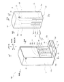
- the blood purification device 100 includes a device main body 10 and a cassette 30 that is detachably attached to the device main body 10.
- the cassette 30 is attached to the apparatus main body 10 by fitting the lower part into the cassette seat 13 of the apparatus main body 10 and fastening the upper claw 35 with the metal fitting 18 of the apparatus main body 10.
- the blood inlet nozzle 51a and the blood outlet nozzle 51b of the cassette 30 are respectively connected to blood vessels of a human body.
- the arrangement direction of the apparatus main body 10 and the cassette 30 will be described as the front-rear direction, the direction perpendicular to the front-rear direction on the horizontal plane as the width direction, and the vertical direction as the up-down direction.
- the casing 31 of the cassette 30 contains a dialyzer 36, a dialysate regeneration column 38, and a water removal container 37, and an outer surface 32 a of a rear plate 32 of the casing 31 has a plurality of elastic members.
- Pump tubes 41 (41a to 41c) are attached.
- the casing 31 forms a tube receiving member that receives the pump tube 41.
- the apparatus main body 10 includes a finger casing 14 for accommodating a plurality of fingers 15, a driving unit 16 for the fingers 15, a control unit 20 for controlling the driving of the driving unit 16, and a housing for accommodating these. And a body 11.
- the finger 15 is a tube pressing body that allows the liquid inside to flow by moving the compression position in the longitudinal direction of the pump tube 41 while compressing the pump tube 41 in the radial direction.
- the finger 15 and the finger casing 14 constitute a peristaltic pump which is a pump unit.
- the blood purification apparatus 100 includes a blood circuit and a dialysate circuit.
- the blood circuit is a liquid circuit that returns blood from the human body flowing from the blood inlet nozzle 51a to the human body from the blood outlet nozzle 51b, and includes a pump tube 41a of the blood pump, a blood-side flow path of the dialyzer 36, a drip chamber, and the like. It consists of connecting pipes to connect.
- the dialysate circuit is a liquid circuit that circulates the dialysate through the dialyzer 36, and includes a dialysate-side flow path of the dialyzer 36, a dialysate regeneration column 38, a dewatering container 37, a pump tube 41b of a dialysate outlet pump, and a dialysate. It is composed of a pump tube 41c of the liquid inlet pump and a connecting pipe connecting these.
- the dialysate regeneration column 38 may be installed at any place in the dialysate circuit.
- the blood purification apparatus 100 is for flowing blood to a blood circuit, flowing dialysate to a dialysate circuit, and removing unnecessary waste and excess water in blood by a dialyzer 36.
- the blood circuit and the dialysate circuit constitute a liquid contact part.
- the cassette 30 includes a dialyzer 36, a dialysate regeneration column 38, a dewatering container 37, a drip chamber, pump tubes 41a to 41c, a blood inlet nozzle 51a, and a blood outlet which constitute a liquid contact part.
- a nozzle 51b and a connection pipe for connecting these nozzles are attached.
- the pump tubes 41a to 41c correspond to a blood pump, a dialysate outlet pump, and a dialysate inlet pump, respectively.
- the present invention is not limited thereto, and the pump tubes 41a to 41c may be blood pumps, dialysate outlet pumps, respectively. And a dialysate inlet pump.
- the housing 11 of the apparatus main body 10 includes a square base 12, L-shaped left and right side plates 11 a, a front plate 11 b attached to the front side of the base 12, and a cassette seat 13. It has. As shown in FIG. 3A, a rib 12a is attached to the center of the base 12, and the cassette seat 13 is mounted on the front portions of the left and right side plates 11a, the front plate 11b, and the ribs 12a. I have. As described above, the cassette receiving seat 13 is attached with a gap between the cassette receiving seat 13 and the base 12.
- the cassette receiving seat 13 has a flat receiving plate 13a mounted on the front portions of the left and right side plates 11a, the front plate 11b and the ribs 12a, and on which the bottom plate 34 of the cassette 30 is placed. And a longitudinal flange 13b erected at the both ends in the width direction of the receiving plate 13a and the front end. The inner surface of the vertical flange 13b is inclined outward so as to easily receive the cassette 30, as shown in FIG.
- Finger casings 14a to 14c constituting a blood pump, a dialysate outlet pump, and a dialysate inlet pump are attached to the upper surface of the base 12.
- the drive units 16a to 16c are attached to the finger casings 14a to 14c.
- the casing 31 of the cassette 30 includes a bottom plate 34, a rear plate 32 erected vertically from the rear edge of the bottom plate 34, and both end edges in the width direction of the bottom plate 34. It includes a side plate 31a standing upright and a front plate 31b standing upright from the front edge of the bottom plate.
- a dialyzer 36, a dialysate regeneration column 38, and a water removal container 37 are accommodated in a space surrounded by the bottom plate 34.
- a dialyzer 36, a dialysate regeneration column 38, and a water removal container 37 are accommodated in a space surrounded by the bottom plate 34, the side plate 31a, the front plate 31b, and the rear plate 32.
- a connection pipe for connecting the dialyzer 36, the dialysate regeneration column 38, and the water removal container 37 is also accommodated in the cassette 30.
- Pump tubes 41a to 41c are attached to the flat outer surface 32a of the rear plate 32 on the device body side. Both ends of the pump tubes 41a to 41c are connected to a blood circuit and a dialysate circuit. The surface on the rear plate 32 side of the pump tubes 41a to 41c is arranged along the flat outer surface 32a of the rear plate 32.
- each of the finger casings 14a to 14c is provided with a vertically extending groove into which each of the pump tubes 41a to 41c is fitted.
- the pump tubes 41 a to 41 c are connected to the grooves of the finger casings 14 a to 14 c and the rear plate. 32 between the flat outer surface 32a.
- the elastic pump tubes 41a to 41c are pressed by the fingers 15a to 15c, respectively, as shown in FIG.
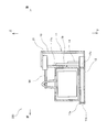
- FIG. 5 is a sectional view taken along the line AA shown in FIG. 4, and is a sectional view of a portion of the cassette 30 that accommodates the water removal container 37.
- a hole 34c is provided in the bottom plate 34 of the cassette 30 in which the water removal container 37 is stored.
- An opening 13c is provided in the cassette seat 13 at a position corresponding to the hole 34c of the bottom plate 34 of the cassette 30.
- the hole 34c and the opening 13c constitute one through hole.
- the spacer 22 is inserted into the through hole formed by the hole 34c and the opening 13c, and the load detecting unit 21 for measuring the load of the water removal container 37 is attached to the upper surface of the base 12 below the spacer 22. I have.
- the spacer 22 projects from the upper surface 34b of the bottom plate 34 when the cassette 30 is attached to the apparatus main body 10 and the lower surface 34a of the bottom plate 34 contacts the upper surface 13d of the cassette seat 13.
- the thickness is such that it can be lifted from the upper surface 34b.
- the load of the water removing container 37 is supported by the upper surface 34 b of the bottom plate 34 of the casing 31.
- the cassette 30 is attached to the housing 11 of the apparatus main body 10, and when the lower surface 34 a of the bottom plate 34 approaches the upper surface 13 d of the cassette seat 13, the upper surface of the spacer 22 projects from the upper surface 34 b of the bottom plate 34.
- the cassette 30 is attached to the housing 11 of the apparatus main body 10 and the lower surface 34a of the bottom plate 34 is in contact with the upper surface 13d of the cassette seat 13, as shown by a solid line in FIG.
- the bottom surface 37a of the water removal container 37 protruding from the upper surface 34b of the bottom plate 34 is floated from the upper surface 34b of the bottom plate 34.
- the spacer 22 is sandwiched between the load detection unit 21 and the bottom surface 37a of the water removal container 37, and transmits the load of the water removal container 37 to the load detection unit 21.
- the water removal container 37 is placed on the load detection unit 21, and the load of the water removal container 37 stored in the cassette 30 can be measured by the load detection unit 21 attached to the apparatus main body 10. it can.
- the load detection unit 21 measures the load of the water removing container 37 that stores the liquid, not the weight of the entire cassette 30, the load of the water removing container 37 can be accurately measured.
- the hole 34 c provided in the bottom plate 34 of the cassette 30, the opening 13 c provided in the cassette receiving seat 13, and the spacer 22 inserted into the hole 34 c and the opening 13 c apply the load of the water removal container 37 to the load.
- the load transmission mechanism that transmits the load to the detection unit 21 is configured.
- the load detecting section 21 and the spacer 22 are described as separate bodies.
- the present invention is not limited to this, and the load detecting section 21 may be provided with a hole 34 c provided in the bottom plate 34 of the cassette 30 and a cassette receiving seat. 13
- the cassette 30 is attached to the housing 11 of the apparatus main body 10, the upper surface of the load detector 21 projects from the upper surface 34 b of the bottom plate 34, and the water removal container 37 detects the load. You may comprise so that it may be directly mounted on the part 21.
- the cassette receiving seat 13 is not provided, and a concave portion is provided in a region corresponding to the hole 34c provided in the bottom plate 34 of the cassette 30 of the base 12, and the load detecting portion 21 is mounted in the concave portion.
- the upper surface of the load detector 21 projects from the upper surface 34b of the bottom plate 34 in a state where the cassette 30 is inserted into the hole 34c and the cassette 30 is attached to the housing 11 of the apparatus main body 10, and the water removal container 37 is placed on the load detector 21. May be configured.
- the upper surface of the spacer 22 protrudes from the upper surface 34b of the bottom plate 34 in a state where the spacer 22 is superimposed on the load detection unit 21 and the cassette 30 is attached to the housing 11 of the apparatus main body 10, and 37 may be configured to be placed on the spacer 22.
- the blood purification apparatus 100 of the present embodiment connects the blood circuit, the dialyzer 36 constituting the dialysate circuit, the water removal container 37, the dialysate regeneration column 38, the pump tubes 41a to 41c, and the devices.
- the connection pipe to be connected is integrally accommodated in the cassette 30 so as to be detachable from the apparatus main body 10. Therefore, dialysis can be performed only by attaching the cassette 30 to the apparatus main body 10 and connecting the blood inlet nozzle 51a and the blood outlet nozzle 51b to a puncture needle inserted into a blood vessel of a human body. Can be simplified.
- the cassette 30 stores all the disposables in the liquid contact portion of the blood circuit and the dialysate circuit, the disposables can be collectively disposed of by disposing the cassette 30 in a disposable manner. Thereby, handling of blood purification apparatus 100 can be simplified.
- the tube pressing body of the pump unit is described as the finger 15, and the tube receiving member is described as the casing 31, and the pressing position is set while the pump tube 41 is pressed in the radial direction.
- a peristaltic pump that pushes the liquid inside by moving it in the longitudinal direction of the tube 41
- the invention is not limited thereto, and an ironing type roller pump may be used.
- the tube pressing body of the pump portion is a rotor
- the pump tube 41 includes an arc portion along the outer periphery of the rotor
- the pump tube 41 includes a circular arc portion along the outer periphery of the pump tube 41. Is pressed by the stator.
- a stator, a rotor, and a pump tube are attached to the cassette 30, a drive unit is attached to the apparatus main body 10, and when the cassette 30 is attached to the apparatus main body 10, the rotor engages with the drive unit.
- the rotor may be detachable from the device main body 10 so that the rotor is separated from the drive unit when the rotor is detached from the device main body 10.
- a pump tube 41 including an arc portion along the outer periphery of the rotor and a stator including an arc portion along the outer periphery of the pump tube 41 are attached to the casing 31 of the cassette 30, and the apparatus is mounted.
- the rotor and the drive unit may be attached to the main body 10, and the cassette 30 may be detachable from the main body 10 so that the pump tube 41 is located between the rotor and the stator.
- the cassette 30 when the cassette 30 is attached to the housing 11 of the apparatus main body 10, the cassette 30 Since the load of only the water removal container 37 accommodated in the blood purification device 100 can be measured, the handling of the blood purification device 100 can be simplified.
- the cassette 30 is described as being attached to the apparatus main body 10 with the metal fittings 18.
- the present invention is not limited to this.
- the cassette 30 may be attached using a fastening part, or the lever may be rotated.
- the cassette 30 may be attached to the apparatus main body 10 by using.
- the blood inlet nozzle 51a and the blood outlet nozzle 51b are attached to the cassette 30, the present invention is not limited to this.
- a part of a tube of the blood circuit toward the human body may come out of the cassette 30. May be configured.
- blood purification apparatuses 200 and 300 will be described with reference to FIGS.
- the description of the same parts as those of the blood purification apparatus 100 described above with reference to FIGS. 1 to 5 will be omitted.
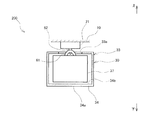
- the blood purification apparatus 200 shown in FIG. 6 is provided with an opening 33 a in the ceiling plate of the front cover 33 in the portion of the cassette 30 that accommodates the water removal container 37, and a handle that is an engaged portion protruding above the water removal container 37.
- a hook 61 as an engaging portion is connected to a load detecting portion 21 attached to the housing 11 of the apparatus main body 10.
- the hook 62 is engaged with the handle 61, the water removal container 37 is suspended from the load detection unit 21, and the bottom surface 37 a of the water removal container 37 is From the upper surface 34b of the bottom plate 34.
- the load of the water removal container 37 can be transmitted to the load detection unit 21 attached to the apparatus main body 10, and the load of the water removal container 37 can be measured by the load detection unit 21.
- the opening 33a of the front cover 33, the handle 61, and the hook 62 constitute a load transmission mechanism that transmits the load of the water removal container 37 to the load detection unit 21.
- the handle 61 of the blood purification apparatus 200 is a projecting handle 63 projecting upward from the opening 33a
- the hook 62 is an arm 64
- the cassette 30 is the mounting of the housing 11 of the apparatus body 10.
- the arm 64 is engaged with the protruding handle 63 protruding from the ceiling plate of the front cover 33 of the cassette 30, and the water removing container 37 is lifted off the upper surface 34b of the bottom plate 34 of the cassette 30.
- the load of the water removal container 37 is transmitted to the load detection unit 21 attached to the apparatus main body 10 by the projecting handle 63 and the arm 64, and the load of the water removal container 37 is measured by the load detection unit 21.
- the opening 33a of the front cover 33, the protruding handle 63, and the arm 64 constitute a load transmission mechanism that transmits the load of the water removal container 37 to the load detection unit 21.
- the blood purification devices 200 and 300 described above have the same effects as the blood purification device 100.
- the blood purification apparatus 110 shown in FIG. 8 is provided below the water removal container 37 accommodated in the cassette 30 when the cassette 30 of the blood purification apparatus 100 described with reference to FIGS.
- the spacer 22 disposed in the region on the side is a heating element 71.
- the heating element 71 is configured such that a part thereof enters the cassette 30 from below when the cassette 30 is attached to the apparatus main body 10.
- Other configurations are the same as those of the blood purification device 100.
- the heating body 71 projects from the upper surface 34 b of the bottom plate 34 to remove water.
- the thickness is such that the bottom surface 37 a of the container 37 floats from the upper surface 34 b of the bottom plate 34.
- the upper surface of the heating body 71 projects from the upper surface 34 b of the bottom plate 34 and the bottom surface of the dewatering container 37.
- 37a is floated from the upper surface 34b of the bottom plate 34.
- the heating element 71 is sandwiched between the load detection unit 21 and the bottom surface 37a of the water removal container 37, and transmits the load of the water removal container 37 to the load detection unit 21.
- the water removal container 37 is placed on the load detection unit 21, and the load of the water removal container 37 stored in the cassette 30 can be measured by the load detection unit 21 attached to the apparatus main body 10. it can.
- the heating element 71 contacts the bottom surface 37a of the water removal container 37 and heats the liquid contained in the water removal container 37.
- the heating body 71 may be configured by a sheet-like or plate-like heater plate or the like. Good.
- an electromagnetic heater or a high-frequency induction heater for heating a metal plate attached to the bottom surface 37a of the water removing container 37 by high-frequency electromagnetic may be used. As described above, by heating the liquid contained in the water removal container 37 by the heating element 71, the dialysate can be heated to maintain the temperature of blood returned to the patient.
- the blood purification apparatus 120 shown in FIG. 9 is the same as the blood purification apparatus 100 described with reference to FIGS. 1 to 5 except that a thin sheet or plate is placed on the spacer 22 disposed in the lower region of the water removal container 37.
- a heating element 72 in a shape of a circle is placed.
- the heating element 72 is configured such that the entire heating element 72 enters the cassette 30 when the cassette 30 is attached to the apparatus main body 10.
- Other configurations are the same as those of the blood purification device 100.
- the spacer 22 has a thickness that protrudes from the upper surface 34b of the bottom plate 34 when the cassette 30 is attached to the apparatus main body 10 and the lower surface 34a of the bottom plate 34 contacts the upper surface 13d of the cassette seat 13. ing.
- the heating element 72 placed on the spacer 22 may be constituted by a thin sheet or plate-like heater plate, a Peltier element, or the like.
- the heating element 72 is moved together with the spacer 22 into the load detecting section 21 and the bottom surface 37 a of the water removal container 37.
- the load of the water removal container 37 housed in the cassette 30 can be measured by the load detection unit 21 attached to the apparatus main body 10.
- the dialysate is heated to maintain the temperature of the blood returned to the patient. be able to.
- the thickness of the heating element 72 is thicker than the state shown in FIG. 9 and the total thickness of the spacer 22 and the heating element 72 is reduced even if the heating element 72 enters the hole 34c.
- the lower surface 34a of the bottom plate 34 comes into contact with the upper surface 13d of the cassette seat 13, the lower surface 34a may have a thickness that protrudes from the upper surface 34b of the bottom plate 34. In this case, when the cassette 30 is attached to the apparatus main body 10, a part of the heating element 72 enters the inside of the cassette 30.
- the blood purification apparatus 130 shown in FIG. 10 has a configuration in which the spacer 22 of the blood purification apparatus 100 described with reference to FIGS. 1 to 5 is an annular member, and a heating body 73 is attached inside.
- the heating element 73 is located in an area below the water removal container 37 accommodated in the cassette 30 when the cassette 30 is attached to the apparatus main body 10.
- the upper portion of the heater 73 penetrates the hole 34c and enters the cassette 30 when the cassette 30 is attached to the apparatus main body 10.
- the height of the heating element 73 may be the same height as the upper surface of the spacer 22 to receive the load of the water removal container 37 and transmit the load to the load detecting unit 21, or may be lower than the height of the upper surface of the spacer 22. Then, it may be configured not to receive the load of the water removal container 37.
- the heating element 73 does not have to penetrate the hole 34c. When the heating element 73 does not penetrate the hole 34 c, the heating element 73 does not enter the cassette 30 and is located near the lower side of the cassette 30. Other configurations are the same as those of the blood purification device 100.
- the ring-shaped spacer 22 is sandwiched between the water removal container 37 and the load detection unit 21 and transmits the load of the water removal container 37 to the load detection unit 21 similarly to the spacer 22 of the blood purification device 100 described above. I do.
- the dialysate can be heated to maintain the temperature of blood returned to the patient.
- the blood purification device 140 which is another modification of the blood purification device 100 described above will be described with reference to FIG.
- the blood purification device 140 has a heating element 74 arranged separately from the spacer 22 and the load detection unit 21 on the base 12 below the opening 13 c provided in the cassette seat 13. .
- the heating element 74 is located below the bottom surface 37 a of the water removal container 37 when the cassette 30 is attached to the apparatus main body 10.
- the upper portion of the heating element 74 penetrates through the hole 34 c and enters the cassette 30 when the cassette 30 is attached to the apparatus main body 10.
- the height of the heating element 74 is higher than the height of the upper surface of the spacer 22. And is configured not to receive the load of the water removal container 37.
- the heating element 74 does not have to penetrate the hole 34c. When the heating element 74 does not penetrate the hole 34c, the heating element 74 does not enter the cassette 30 and is located near the lower side of the cassette 30.
- the heating element 74 may be, for example, an electromagnetic heater or a high-frequency induction heater. Further, the heating element 74 may be formed of a sheet-like or plate-like heater plate, a Peltier element, or the like, and may be attached to the upper side of the base 12 below the opening 13c.
- the heating element 74 may be disposed in a region below the water removal container 37 accommodated in the cassette 30 when the cassette 30 is attached to the apparatus main body 10, and may be arranged in a region below the opening 13c. Instead, it may be mounted on the base 12 below the receiving plate 13a of the cassette seat 13 around the opening 13c.
- the blood purification device 140 heats the liquid contained in the water removal container 37 by the heating element 74, thereby heating the dialysate to maintain the temperature of the blood returned to the patient. be able to.
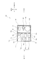
- the heating element 75 is arranged so that when the cassette 30 of the apparatus main body 10 is attached to the apparatus main body 10, it is located near the side surface of the cassette 30.
- Other configurations are the same as those of the blood purification device 100.
- the finger casings 14a to 14c are attached to the side where the dialysate regeneration column 38 is arranged, and the finger casing 14a and the side plate 11a of the housing 11 of the apparatus main body 10 are attached.
- a space is provided therebetween, and a heating element 75 is attached to this space.
- the heating element 75 is located at a position facing the water removal container 37 accommodated in the cassette 30 in the front-rear direction with the rear plate 32 of the cassette 30 interposed therebetween.
- the heating element 75 is a non-contact type heater for heating the water removing container 37 or the liquid contained in the water removing container 37 through the rear plate 32 of the cassette 30 in a non-contact manner.
- the heating element 75 may be, for example, an electromagnetic heater or an optical heater that irradiates a light beam to the water removal container 37 through a slit provided in the rear plate 32 to heat the water removal container 37.
- the blood purification device 150 like the blood purification devices 110, 120, and 130, heats the liquid contained in the water removal container 37 by the heating element 75, thereby heating the dialysate and returning blood to the patient. Temperature can be maintained.
- the blood purification apparatus 160 shown in FIG. 13 has the heating element 75 housed in the cassette 30 when the cassette 30 is attached to the apparatus main body 10, as opposed to the blood purification apparatus 150 described with reference to FIG.
- the dialysate regeneration column 38 and the rear plate 32 of the cassette 30 are opposed to each other in the front-rear direction.
- Other configurations are the same as those of the blood purification device 150 described with reference to FIG.
- the blood purification device 160 can maintain the temperature of the blood returned to the patient by heating the dialysate by heating the liquid stored in the dialysate regeneration column 38 by the heating element 75.
- the blood purification apparatus 170 shown in FIG. 14 is provided with an opening 32b in the rear plate 32 of the casing 31 of the cassette 30 of the blood purification apparatus 150 described with reference to FIG.
- the hot air generator 76 is arranged in the apparatus main body 10 facing in the direction.
- the blood purification device 170 allows the hot air from the hot air generator 76 to flow into the casing 31 of the cassette 30 through the opening 32b, and the dialyzer 36, the water removal container 37, and the dialysate regeneration column accommodated in the cassette 30 are provided. By heating 38, the dialysate can be heated to maintain the temperature of the blood returned to the patient.
- a blood purification device 180 shown in FIG. 15 has a configuration in which a concave portion 37b is provided at the bottom of the water removing container 37, and the heating element 74a enters the concave portion 37b when the cassette 30 is attached to the device main body 10.
- the blood purification device 180 has a configuration in which the heating element 74 of the blood purification apparatus 140 described with reference to FIG. 11 is a high heating element 74 a, and a concave portion 37 b is provided at the bottom of the water removing container 37.
- the heating element 74a enters the inside of the cassette 30 and removes the heat from the cassette 30 as shown in FIG.
- the water enters the recess 37 b from below the water container 37.
- the bottom surface 37 a of the water removal container 37 hits the upper surface of the spacer 22, and the load of the water removal container 37 is detected by the load detection unit 21.
- the height of the heating element 74a is a height that does not contact the upper part of the concave portion 37b, and does not transmit the load of the water removal container 37.
- the heating element 74a enters the concave portion 37b of the water removal container 37, so that the water removal container 37 can be heated more effectively.
- the heating element 74a has been described as entering the inside of the cassette 30 from below the cassette 30, but the invention is not limited to this.
- an opening is provided in the rear plate 32 of the cassette 30, the heating element 74a is attached to the partition plate 11c of the apparatus main body 10, and when the cassette 30 is attached to the apparatus main body 10, the heating element 74a may enter.
- the heating element 74a is attached to the upper part of the apparatus main body 10 and an opening is provided in the ceiling plate of the cassette 30.
- the heating element 74a enters the inside of the cassette 30 from above the cassette 30. You may do so.
- the blood purifying apparatus 310 shown in FIG. 17 is similar to the blood purifying apparatus 300 described with reference to FIG. 7 in that when the cassette 30 is attached to the apparatus main body 10, the water removing container 37 is moved from the arm 64 of the load detecting section 21.
- the heating element 77 is arranged so as to protrude from the partition plate 11c on the cassette 30 side of the housing 11 of the apparatus main body 10 to a position above the cassette 30.
- the heating element 77 is arranged so as to be located near the upper side of the cassette 30 when the cassette 30 is attached to the apparatus main body 10.
- the blood purification apparatus 320 shown in FIG. 18 has a configuration in which the heating element 78 is placed in the cassette receiving seat 13 so that the heating element 78 is disposed near the lower side of the cassette 30 when the cassette 30 is attached to the apparatus main body 10. It is arranged on the lower surface of the plate 13a.
- a blood purification apparatus 330 shown in FIG. 19 has a heating element 79 attached to a partition plate 11c on the cassette 30 side inside the housing 11 of the apparatus main body 10.
- the heating body 79 is arranged so as to be located near the side surface of the cassette 30 when the cassette 30 is attached to the apparatus main body 10.
- the blood purification devices 310, 320, and 330 described with reference to FIGS. 17 and 18 use the dialyser 36, the water removal container 37, and the dialysate regeneration column 38 that are housed in the cassette 30 by the heating elements 77, 78, and 79. By heating, the dialysate can be heated to maintain the temperature of the blood returned to the patient.
Landscapes
- Health & Medical Sciences (AREA)
- Heart & Thoracic Surgery (AREA)
- Vascular Medicine (AREA)
- Hematology (AREA)
- Engineering & Computer Science (AREA)
- Anesthesiology (AREA)
- Biomedical Technology (AREA)
- Life Sciences & Earth Sciences (AREA)
- Animal Behavior & Ethology (AREA)
- General Health & Medical Sciences (AREA)
- Public Health (AREA)
- Veterinary Medicine (AREA)
- Urology & Nephrology (AREA)
- Emergency Medicine (AREA)
- Cardiology (AREA)
- External Artificial Organs (AREA)
Abstract
L'invention concerne un dispositif (100) de purification du sang qui comporte un corps (10) de dispositif et une cassette (30). La cassette (30) comporte un boîtier (31) dans lequel est logé un contenant (37) pour l'eau évacuée ainsi que des tubes (41) de pompage. Le corps (10) de dispositif comporte des doigts (15), une partie (16) d'actionnement et une enveloppe (11). La cassette (30) est amovible par rapport à l'enveloppe (11) du corps (10) de dispositif, de façon à ce que les tubes (41) de pompage soient positionnés entre les doigts (15) et la surface extérieure du boîtier (31).
Priority Applications (4)
| Application Number | Priority Date | Filing Date | Title |
|---|---|---|---|
| EP19853863.9A EP3845257B1 (fr) | 2018-08-27 | 2019-08-27 | Dispositif de purification du sang |
| JP2020539466A JP7332608B2 (ja) | 2018-08-27 | 2019-08-27 | 血液浄化装置 |
| CN201980055485.5A CN112601562B (zh) | 2018-08-27 | 2019-08-27 | 血液净化装置 |
| US17/269,856 US11918717B2 (en) | 2018-08-27 | 2019-08-27 | Blood purification device |
Applications Claiming Priority (2)
| Application Number | Priority Date | Filing Date | Title |
|---|---|---|---|
| JP2018-158144 | 2018-08-27 | ||
| JP2018158144 | 2018-08-27 |
Publications (1)
| Publication Number | Publication Date |
|---|---|
| WO2020045385A1 true WO2020045385A1 (fr) | 2020-03-05 |
Family
ID=69643241
Family Applications (1)
| Application Number | Title | Priority Date | Filing Date |
|---|---|---|---|
| PCT/JP2019/033425 Ceased WO2020045385A1 (fr) | 2018-08-27 | 2019-08-27 | Dispositif de purification du sang |
Country Status (5)
| Country | Link |
|---|---|
| US (1) | US11918717B2 (fr) |
| EP (1) | EP3845257B1 (fr) |
| JP (1) | JP7332608B2 (fr) |
| CN (1) | CN112601562B (fr) |
| WO (1) | WO2020045385A1 (fr) |
Cited By (1)
| Publication number | Priority date | Publication date | Assignee | Title |
|---|---|---|---|---|
| WO2024004950A1 (fr) * | 2022-06-28 | 2024-01-04 | 日機装株式会社 | Dispositif de purification du sang |
Citations (5)
| Publication number | Priority date | Publication date | Assignee | Title |
|---|---|---|---|---|
| JPH0630993A (ja) * | 1992-07-13 | 1994-02-08 | Terumo Corp | 輸液ポンプ用の閉塞検知装置 |
| JP2003010316A (ja) * | 1991-09-10 | 2003-01-14 | Hospal Ind | 多機能装置 |
| JP2007097746A (ja) | 2005-10-03 | 2007-04-19 | Japan Science & Technology Agency | 体液浄化カセットの成形方法 |
| WO2008099890A1 (fr) * | 2007-02-15 | 2008-08-21 | Asahi Kasei Kuraray Medical Co., Ltd. | Système de purification du sang |
| JP5657726B2 (ja) | 2002-07-19 | 2015-01-21 | バクスター・インターナショナル・インコーポレイテッドBaxter International Incorp0Rated | 血液透析のための重量センサにより制御される吸収剤システム |
Family Cites Families (4)
| Publication number | Priority date | Publication date | Assignee | Title |
|---|---|---|---|---|
| US4661246A (en) | 1984-10-01 | 1987-04-28 | Ash Medical Systems, Inc. | Dialysis instrument with dialysate side pump for moving body fluids |
| EP1156840B1 (fr) | 1999-03-02 | 2004-01-14 | Infomed S.A. | Tubulure pour l'epuration extracorporelle du sang et utilisation de cette tubulure |
| JP4259167B2 (ja) | 2003-04-14 | 2009-04-30 | ニプロ株式会社 | 持続的血液浄化装置 |
| CN102784422B (zh) | 2007-09-19 | 2015-05-06 | 弗雷塞尼斯医疗保健控股公司 | 透析系统及相关部件 |
-
2019
- 2019-08-27 EP EP19853863.9A patent/EP3845257B1/fr active Active
- 2019-08-27 US US17/269,856 patent/US11918717B2/en active Active
- 2019-08-27 JP JP2020539466A patent/JP7332608B2/ja active Active
- 2019-08-27 CN CN201980055485.5A patent/CN112601562B/zh active Active
- 2019-08-27 WO PCT/JP2019/033425 patent/WO2020045385A1/fr not_active Ceased
Patent Citations (5)
| Publication number | Priority date | Publication date | Assignee | Title |
|---|---|---|---|---|
| JP2003010316A (ja) * | 1991-09-10 | 2003-01-14 | Hospal Ind | 多機能装置 |
| JPH0630993A (ja) * | 1992-07-13 | 1994-02-08 | Terumo Corp | 輸液ポンプ用の閉塞検知装置 |
| JP5657726B2 (ja) | 2002-07-19 | 2015-01-21 | バクスター・インターナショナル・インコーポレイテッドBaxter International Incorp0Rated | 血液透析のための重量センサにより制御される吸収剤システム |
| JP2007097746A (ja) | 2005-10-03 | 2007-04-19 | Japan Science & Technology Agency | 体液浄化カセットの成形方法 |
| WO2008099890A1 (fr) * | 2007-02-15 | 2008-08-21 | Asahi Kasei Kuraray Medical Co., Ltd. | Système de purification du sang |
Cited By (2)
| Publication number | Priority date | Publication date | Assignee | Title |
|---|---|---|---|---|
| WO2024004950A1 (fr) * | 2022-06-28 | 2024-01-04 | 日機装株式会社 | Dispositif de purification du sang |
| JPWO2024004950A1 (fr) * | 2022-06-28 | 2024-01-04 |
Also Published As
| Publication number | Publication date |
|---|---|
| EP3845257A1 (fr) | 2021-07-07 |
| JPWO2020045385A1 (ja) | 2021-10-07 |
| US20210170085A1 (en) | 2021-06-10 |
| EP3845257B1 (fr) | 2024-10-09 |
| EP3845257A4 (fr) | 2022-05-25 |
| US11918717B2 (en) | 2024-03-05 |
| CN112601562B (zh) | 2023-08-29 |
| JP7332608B2 (ja) | 2023-08-23 |
| CN112601562A (zh) | 2021-04-02 |
Similar Documents
| Publication | Publication Date | Title |
|---|---|---|
| JP5465540B2 (ja) | 誘導加熱を有する透析システム | |
| US7998115B2 (en) | Dialysis system having optical flowrate detection | |
| US11725645B2 (en) | Automated control mechanisms and methods for controlling fluid flow in a hemodialysis apparatus | |
| JP6855518B2 (ja) | 改善したリザーバ加熱システムを有する携帯型透析装置 | |
| KR102716260B1 (ko) | 전기 주전자 | |
| JP6549203B2 (ja) | 血液処置システムおよび方法 | |
| JP6685089B2 (ja) | 医療用液圧検出装置 | |
| US12421952B2 (en) | Reciprocating diaphragm pumps for blood treatment systems and methods | |
| CN102639201B (zh) | 模块化便携透析系统 | |
| JP2002503115A (ja) | モジュラー型在宅透析システム | |
| CN114945392A (zh) | 流体管理系统和方法 | |
| US7223336B2 (en) | Integrated blood treatment module and extracorporeal blood treatment apparatus | |
| DK152963B (da) | Apparat til rengoering af taepper og lignende | |
| EP2219705B2 (fr) | Appareil médical pour un traitement extracorporel | |
| KR102716254B1 (ko) | 전기 주전자 | |
| WO2020045385A1 (fr) | Dispositif de purification du sang | |
| AU2004210213A2 (en) | Support element for an integrated blood treatment module | |
| EP3903849B1 (fr) | Dispositif de purification du sang | |
| US20130276908A1 (en) | Device for extra-corporal blood treatment with leakage sensor | |
| JP6128913B2 (ja) | 圧力チャンバー | |
| CN215780383U (zh) | 漏液检测装置及血液净化装置 | |
| EP0143619A1 (fr) | Chaudière à eau transportable | |
| JP6741486B2 (ja) | 水検知装置および加熱調理器 | |
| CN103357077A (zh) | 具有倾斜传感器和填充传感器的负压伤口治疗泵 |
Legal Events
| Date | Code | Title | Description |
|---|---|---|---|
| 121 | Ep: the epo has been informed by wipo that ep was designated in this application |
Ref document number: 19853863 Country of ref document: EP Kind code of ref document: A1 |
|
| ENP | Entry into the national phase |
Ref document number: 2020539466 Country of ref document: JP Kind code of ref document: A |
|
| NENP | Non-entry into the national phase |
Ref country code: DE |
|
| ENP | Entry into the national phase |
Ref document number: 2019853863 Country of ref document: EP Effective date: 20210329 |