WO2020049971A1 - Procédé de mesure de surface, procédé de fabrication de composant, procédé d'inspection de composant et dispositif de mesure de composant - Google Patents
Procédé de mesure de surface, procédé de fabrication de composant, procédé d'inspection de composant et dispositif de mesure de composant Download PDFInfo
- Publication number
- WO2020049971A1 WO2020049971A1 PCT/JP2019/031930 JP2019031930W WO2020049971A1 WO 2020049971 A1 WO2020049971 A1 WO 2020049971A1 JP 2019031930 W JP2019031930 W JP 2019031930W WO 2020049971 A1 WO2020049971 A1 WO 2020049971A1
- Authority
- WO
- WIPO (PCT)
- Prior art keywords
- screen
- measured
- optical image
- component
- piston rod
- Prior art date
- Legal status (The legal status is an assumption and is not a legal conclusion. Google has not performed a legal analysis and makes no representation as to the accuracy of the status listed.)
- Ceased
Links
Images


Classifications
-
- G—PHYSICS
- G01—MEASURING; TESTING
- G01B—MEASURING LENGTH, THICKNESS OR SIMILAR LINEAR DIMENSIONS; MEASURING ANGLES; MEASURING AREAS; MEASURING IRREGULARITIES OF SURFACES OR CONTOURS
- G01B11/00—Measuring arrangements characterised by the use of optical techniques
- G01B11/30—Measuring arrangements characterised by the use of optical techniques for measuring roughness or irregularity of surfaces
- G01B11/303—Measuring arrangements characterised by the use of optical techniques for measuring roughness or irregularity of surfaces using photoelectric detection means
-
- G—PHYSICS
- G01—MEASURING; TESTING
- G01N—INVESTIGATING OR ANALYSING MATERIALS BY DETERMINING THEIR CHEMICAL OR PHYSICAL PROPERTIES
- G01N21/00—Investigating or analysing materials by the use of optical means, i.e. using sub-millimetre waves, infrared, visible or ultraviolet light
- G01N21/84—Systems specially adapted for particular applications
- G01N21/88—Investigating the presence of flaws or contamination
- G01N21/8851—Scan or image signal processing specially adapted therefor, e.g. for scan signal adjustment, for detecting different kinds of defects, for compensating for structures, markings, edges
-
- G—PHYSICS
- G01—MEASURING; TESTING
- G01N—INVESTIGATING OR ANALYSING MATERIALS BY DETERMINING THEIR CHEMICAL OR PHYSICAL PROPERTIES
- G01N21/00—Investigating or analysing materials by the use of optical means, i.e. using sub-millimetre waves, infrared, visible or ultraviolet light
- G01N21/84—Systems specially adapted for particular applications
- G01N21/88—Investigating the presence of flaws or contamination
- G01N21/95—Investigating the presence of flaws or contamination characterised by the material or shape of the object to be examined
- G01N21/952—Inspecting the exterior surface of cylindrical bodies or wires
-
- B—PERFORMING OPERATIONS; TRANSPORTING
- B24—GRINDING; POLISHING
- B24B—MACHINES, DEVICES, OR PROCESSES FOR GRINDING OR POLISHING; DRESSING OR CONDITIONING OF ABRADING SURFACES; FEEDING OF GRINDING, POLISHING, OR LAPPING AGENTS
- B24B49/00—Measuring or gauging equipment for controlling the feed movement of the grinding tool or work; Arrangements of indicating or measuring equipment, e.g. for indicating the start of the grinding operation
- B24B49/12—Measuring or gauging equipment for controlling the feed movement of the grinding tool or work; Arrangements of indicating or measuring equipment, e.g. for indicating the start of the grinding operation involving optical means
-
- G—PHYSICS
- G01—MEASURING; TESTING
- G01N—INVESTIGATING OR ANALYSING MATERIALS BY DETERMINING THEIR CHEMICAL OR PHYSICAL PROPERTIES
- G01N21/00—Investigating or analysing materials by the use of optical means, i.e. using sub-millimetre waves, infrared, visible or ultraviolet light
- G01N21/17—Systems in which incident light is modified in accordance with the properties of the material investigated
- G01N21/55—Specular reflectivity
Definitions
- the present invention relates to a surface measuring method, a component manufacturing method, a component inspection method, and a component measuring device.
- the present invention provides a surface measurement method, a component manufacturing method, a component inspection method, and a component measurement device capable of reducing the influence of speckle noise.
- a surface measurement method includes irradiating a coherent light beam to a surface to be measured, and projecting a light reflected on the surface to be measured onto a screen to form an optical image, An optical image is captured by an optical sensor. The imaging by the optical sensor is performed in a state where the screen is continuously moved in one direction.
- a method of manufacturing a component having a surface to be measured comprising: a processing step of mirror-finishing the surface to be measured; and irradiating a coherent light beam onto the surface to be measured.
- the inspection step is performed in a state where the screen is continuously moved in one direction.
- a method for inspecting a component having a mirror-like surface to be measured includes irradiating a coherent light beam to the surface to be measured, and reflecting light reflected by the surface to be measured on a screen.
- the imaging step is performed in a state where the screen is continuously moved in one direction at a constant speed regardless of the width direction position of the optical image.
- a measuring device for measuring a measured surface of a component, comprising: an irradiator configured to form a coherent light beam into a slit shape and to emit the beam toward the measured surface of the component; A moving unit that relatively moves the light beam irradiated from the unit and the measured surface of the component, a screen on which reflected light reflected on the measured surface of the component is projected to form an optical image, An optical sensor that captures an optical image and a drive source that continuously moves the screen in one direction are provided.
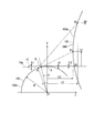
- FIG. 3 is a diagram for explaining the principle of the present invention showing a state in which an optical image formed by reflected light reflected on the surface of a cylindrical component is enlarged and projected on a screen.
- FIG. 2 is a diagram showing a light irradiation area on the component shown in FIG. 1.
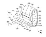
- FIG. 2 is a perspective view illustrating a shock absorber including a piston rod to be measured according to the first embodiment.
- FIG. 3 is a process diagram illustrating a manufacturing process of a piston rod to be measured according to the first embodiment. It is a flowchart which shows the surface inspection process of the piston rod which is a measurement object of 1st Embodiment.
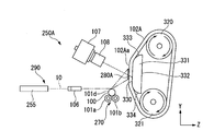
- FIG. 2 is a diagram illustrating an inspection device including the measurement device according to the first embodiment and a transport device.
- FIG. 2 is an enlarged view for explaining an optical image in a state where irradiation light is irradiated on a surface of a piston rod to be measured in the first embodiment.
- FIG. 2 is a front view of an observation position of an optical image on a screen viewed from a laser oscillator side in the first embodiment. It is a front view explaining scanning by a line sensor camera of a measuring device of a 1st embodiment.
- FIG. 7 is image data showing a reflected light intensity distribution on a screen of a concave defect.
- 17 is a microscope image of the concave defect in FIG. 9 is image data showing a reflected light intensity distribution on a screen of a convex defect.
- 19 is a microscope image of the convex defect of FIG.
- FIG. 4 is a process chart of the image processing of the first embodiment.
- 5 is image data of an input image processed in the image processing of the first embodiment.
- 7 is image data after high-pass filter image processing of the image processing of the first embodiment. It is image data after smooth image processing of image processing of a 1st embodiment. It is the image data of the Mahalanobis image of the image processing of the first embodiment. It is image data after the binarization processing of the image processing of the first embodiment. 7 is output image data of the image processing of the first embodiment. It is a side view which shows the modification of the measuring device of 1st Embodiment which concerns on this invention.
- FIG. 1 is a diagram showing a state in which an optical image formed by reflected light reflected on the surface of a cylindrical component is enlarged and projected on a screen.
- FIG. 2 is a diagram showing an irradiation area on the component shown in FIG.
- the component 150 to be inspected is a member having a central axis O and a circular cross section. That is, the component 150 is a columnar or cylindrical member.
- FIG. 1 is a diagram in which the component 150 is cut along a plane orthogonal to the axial direction.
- the component 150 has a vertex A on the Y axis.
- the X direction, the Y direction, and the Z direction are respectively as illustrated.
- the Y direction and the Z direction are orthogonal, and the X direction is orthogonal to the Y direction and the Z direction.
- the Y axis is located on a straight line connecting the central axis O of the component 150 and the vertex A.
- the component 150 is irradiated with a belt-shaped irradiation light 151 having a width (length in the X direction) W ⁇ a thickness (length in the Y direction) t1.
- the thickness t1 of the irradiation light 151 is smaller than the radius R of the component 150.
- the optical axis 151a of the irradiation light 151 is parallel to the XZ plane.
- the irradiation light 151 is applied to a range of the thickness t1 from above the vertex A of the component 150 in the Y direction to the illumination incident point B on the outer peripheral surface 150a of the component 150. That is, the irradiation light 151 includes a light beam that becomes a contact point with the vertex A of the component 150.
- This light beam is substantially parallel to the optical axis 151a of the irradiation light 151. Therefore, the irradiation light 151 is irradiated from the tangent direction to the vertex A of the component 150.
- the optical axis 151a of the irradiation light 151 is located at a point P on the outer peripheral surface 150a of the component 150 between the vertex A of the component 150 and the illumination incident point B in the Y direction.
- a cylindrical screen 152 is disposed at a position separated from the central axis O of the part 150.
- the screen 152 has a cylindrical shape, and its central axis is arranged parallel to the X axis. That is, the outer surface 152a of the screen 152 is a cylindrical surface, and the central axis of the outer surface 152a is arranged parallel to the X axis.
- a part of the irradiation light 151 irradiates the arc portion AB on the outer peripheral surface 150a of the component 150.
- the remaining part of the irradiation light 151 above the vertex A of the component 150 passes through the outer peripheral surface 150a of the component 150 as reference light and is directly irradiated on the screen 152 to form a reference image.
- the vertex A of the component 150 and the reference position S0 projected on the screen 152 have the same height in the Y direction.
- the height position of 150 is adjusted.
- the point S0 on the screen 152 is defined as a reference position.
- all of the irradiation light 151 below the reference position S0 irradiates the arc portion AB of the outer peripheral surface 150a of the component 150 in a band shape having a width W.
- an irradiation area 153 for irradiating the arc portion AB on the outer peripheral surface 150 a of the component 150 is hatched with oblique lines.
- the irradiation light 151 is emitted from an irradiation light source (not shown) to the component 150 and the screen 152 via the cylindrical lens 160.
- the angle of the point P of the component 150 with respect to the Y axis is ⁇ .
- the point P of the component 150 is defined as a specific position. As described above, the position of the optical axis 151a of the irradiation light 151 coincides with the specific position P. The incident angle and the reflection angle of the irradiation light 151 at the specific position P are both u1. The light beam reflected at the specific position P reaches a point S1 on the outer peripheral surface 152a of the screen 152.
- the height h1 from the reference position S0 to the point S1 on the screen 152 includes the distance L1 in the Z direction from the central axis O of the component 150 to the point S1. It can be obtained by equation (1).
- h1 tan ( ⁇ 1) ⁇ (L1 + R ⁇ sin ⁇ ) ⁇ R (1 ⁇ cos ⁇ ) (1)
- the thickness t2 of the irradiation light 151 directly applied to the screen 152 is t1 / 2 ⁇ R (1-cos ⁇ ).
- the incident angle and the reflection angle of the irradiation light 151 are both u2, and the light beam reflected at the point Q is reflected at a point S2 on the screen 152.
- the elevation angle of the reflected light from the point Q is ⁇ 2
- the height h2 from the reference position S0 to the point S2 on the outer peripheral surface 152a of the screen 152 is the distance in the Z direction from the central axis O of the component 150 to the point S2. It can be obtained by equation (2) including L2.
- H2 tan ( ⁇ 2) ⁇ (L2 + R ⁇ sin ( ⁇ + ⁇ ))-R (1-cos ( ⁇ + ⁇ )) (2)
- ⁇ is a central angle with respect to the arc portion PQ.
- the light ray reflected at the illumination incident point B on the outer periphery of the component 150 reaches the point S3 on the screen 152. Therefore, the irradiation light irradiated on the arc portion AB is projected on a range of points S0 to S3 on the screen 152.
- the uneven portion of the outer peripheral surface 150a of the component 150 is made to appear as a shadow of the reflected light projected on the screen 152.
- the height h1 of the point S1 at which the reflected light of the specific position P of the component 150 is projected on the screen 152 from the reference position S0 is the radius R Is 11 mm, 5.39 mm, and when the radius R is 14 mm, 5.30 mm. That is, the difference between h1 when the radius R is 11 mm and 14 mm is only 0.09 mm.
- This value is smaller than the pixel size c (for example, about 55 ⁇ m) of one pixel of the line sensor camera (see the line sensor camera 107 in FIG. 7) on the outer peripheral surface 152a of the screen 152.
- the height of the component 150 or the screen 152 is adjusted in accordance with the radius of the component 150 so that the reference position S0 of the screen matches the vertex A of the component 150.
- the enlargement magnification of the minute region (arc portion PQ) on the component 150 is calculated. If the arc portion PQ is set to d, the magnification M in the circumferential direction on the outer peripheral surface 152a of the screen 152 can be obtained by Expression (3).
- H1 and h2 are obtained from Expressions (1) and (2), respectively.
- the defect detection sensitivity increases as the incident angle of the irradiation light 151 with respect to the specific position P approaches 90 °. For this reason, if it is assumed that ⁇ is inspected under a condition of about 5 ° or less, it can be handled as R (1 ⁇ cos ⁇ ) ⁇ 0, which is the second term of equation (1). Further, if L1 >> R, it can be approximated as (L1 + R ⁇ sin ( ⁇ + ⁇ )) ⁇ L. Therefore, equation (3) can be interpreted as simplified to equation (4).
- ⁇ M L1 (tan ( ⁇ 2) ⁇ tan ( ⁇ 1)) / d ⁇ (4)
- a component having a cylindrical outer peripheral surface is manufactured while measuring and inspecting the cylindrical outer peripheral surface of the surface.
- examples of such components include a piston rod of a shock absorber, a piston pin of an internal combustion engine, and a piston of a rotary pump, a hydraulic cylinder, a brake device, and the like.
- the shock absorber 201 includes a cylindrical cylinder 202 having a bottom, a piston rod 100 having one end inserted into the cylinder 202 and the other end extending outside from an opening (not shown) of the cylinder 202, and an opening side of the cylinder 202. And a cover 204 attached to the cylinder 202 so as to cover the The cover 204 covers a sealing member (not shown) that is attached to the opening side of the cylinder 202 and seals between the cylinder 202 and the piston rod 100. Further, the shock absorber 201 has a piston 207 fixed by a nut 206 to an end of the piston rod 100 inside the cylinder 202. The piston 207 partitions the inside of the cylinder 202 into two chambers.
- the piston 207 moves integrally with the piston rod 100 and slides inside the cylinder 202.
- the shock absorber 201 generates a damping force by suppressing the movement of the working fluid between the two chambers generated in the flow path of the piston 207 due to the axial movement of the piston rod 100 with respect to the cylinder 202.
- the shock absorber 201 has a spring seat 210, a main bracket 211, a harness bracket 212, and a hose bracket 213 attached to the outside of the cylinder 202.
- the spring seat 210 holds the spring between itself and the sprung portion of the vehicle.
- the main bracket 211 connects the shock absorber 201 to the unsprung portion of the vehicle.
- the harness bracket 212 supports the harness.
- the hose bracket 213 supports the hose.
- the shock absorber 201 is incorporated into a vehicle body as a suspension strut assembly together with a spring (not shown) supported by a spring seat 210.
- the roundness and cylindricity of the piston rod 100 are controlled on the order of micrometers, and the arithmetic average roughness (Ra) of the surface is 0.05 ⁇ m or less.
- the piston rod 100 is a cylindrical part made of low carbon steel such as S25C. After quenching and forming steps, the piston rod 100 is subjected to a surface treatment to finish its surface flat, and then put into an assembling step.
- the piston rod 100 to be inspected has, for example, a diameter of about 22 mm and a total length of about 250 mm.
- Connecting parts 100a and 100b for mechanical connection are formed at both ends of the piston rod 100.
- the outer peripheral surface 100d of the main shaft portion 100c between the connecting portions 100a and 100b is in sliding contact with the seal member.
- the outer peripheral surface 100d of the main shaft portion 100c is to be inspected.
- the connection portions 100a and 100b at both ends are not to be inspected.
- the connecting portion 100a is connected to a sprung portion of the vehicle, and a piston 207 is attached to the connecting portion 100b by a nut 206.
- the piston rod 100 After passing through the cutting step and the heat treatment step in this order, as shown in FIG. 4, the piston rod 100 has a rough polishing step SP1, a medium polishing step SP2, a super finish polishing step SP3, a wet cleaning step SP4, and an etching step SP5.
- the chromium plating step SP6, the buff polishing step SP7, and the surface inspection step SP8 are performed in this order.
- the buff polishing step SP7 is a mirror finishing step of making the outer peripheral surface 100d of the main shaft portion 100c a mirror surface, in other words, a glossy surface.
- the buff polishing step SP7 is a processing step of mirror-finishing the outer peripheral surface 100d of the main shaft portion 100c.
- the surface inspection step SP8 is an inspection step of inspecting the outer peripheral surface 100d of the piston rod 100 having the mirror-like outer peripheral surface 100d.
- the post-processing unloading step SP8-1 for unloading the piston rod 100 is performed.
- the inspection device 230 uses the measuring device 250 to image and measure the outer peripheral surface 100d of the main shaft portion 100c of the piston rod 100 as a surface to be measured. Is performed, and a defect detection step SP8-4 for detecting a defect on the outer peripheral surface 100d of the piston rod 100 by image processing is performed.
- the outer peripheral surface 100d which is the surface to be measured, has a cylindrical surface. Therefore, the surface to be measured has a convex shape convex outward.
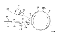
- a measuring device 250 for measuring the outer peripheral surface 100d of the piston rod 100 which is a component to be measured, includes a laser slit light source 255 for expanding a light beam into a slit shape, a cylindrical lens 106, and a piston rod 100.
- rollers 101a and 101b for rotating the lens, a line sensor camera 107 (optical sensor), and a screen 102.
- Each of the rollers 101a and 101b has a cylindrical outer peripheral surface.
- the rollers 101a and 101b are arranged so that their cylindrical central axes on the outer peripheral surface are parallel to each other, and are supported so as to be rotatable about these central axes.
- the piston rod 100 is unloaded in the post-processing unloading step SP8-1 shown in FIG. 5, and is transferred by the transfer device 260 shown in FIG. 6, and the inspection device shown in FIG. In the loading step SP8-2, the wafer is loaded into the inspection device 230.
- the piston rod 100 carried into the inspection device 230 is mounted across the rollers 101a and 101b of the measurement device 250.
- the roller 101a and the roller 101b have the same diameter.
- the roller 101a and the roller 101b are arranged at the same height position in the Y direction, which is the height direction, with the axis parallel to the horizontal X axis and separated in the horizontal Z direction orthogonal to the X axis. Have been.
- the piston rod 100 is mounted on the rollers 101a and 101b such that the axis is located on the center line of the boundary between the rollers 101a and 101b.
- the roller 101a is connected to a roller drive motor 103.
- the roller 101b is freely rotatable with respect to the axis.
- the roller drive motor 103 By rotating the roller drive motor 103, the roller 101a rotates, and the piston rod 100 and the roller 101b rotate. That is, by controlling the rotation of the roller drive motor 103, the rotation of the piston rod 100 can be controlled at an arbitrary speed.
- the roller drive motor 103 and the rollers 101a and 101b constitute a moving unit 270 that rotates the piston rod 100, which is a component to be inspected, and moves the outer peripheral surface 100d.
- the moving unit 270 including the roller 101a and the roller 101b is mounted on a moving stage, and is integrally movable in a vertical direction (Y direction).
- the laser slit light source 255 includes a laser oscillator 104, which is a coherent light source that irradiates the piston rod 100 with laser light (irradiation light), and a Powell lens 105.
- the laser oscillator 104 outputs, for example, a laser beam having a wavelength of 670 nm and a diameter of 2 mm, that is, a coherent light beam (also referred to as “irradiation light”) 10.
- the output of the laser oscillator 104 is, for example, about 100 mW.
- the light beam 10 output from the laser oscillator 104 is expanded by the Powell lens 105 into a fan shape only on the XZ plane, that is, only on the horizontal plane.
- the Powell lens 105 is a cylindrical lens having a rounded ridge. Powell lens 105 is also called a laser line generator lens. The Powell lens 105 extends, for example, the light beam 10 having a diameter of 2 mm from the laser oscillator 104 to a full angle of 30 °.
- the laser oscillator 104 is a single mode laser, and the intensity distribution of the output beam is a Gaussian distribution, which is referred to as a beam diameter with a 1 / e 2 diameter. That is, the beam diameter is the width at the intensity when the intensity falls to 1 / e 2 (13.6%) from the peak intensity value.
- the cylindrical lens 106 has a curvature only in the XZ plane, as shown in FIG.
- the cylindrical lens 106 has the function of a convex lens in the horizontal direction, and does not have the function of a lens in the vertical direction.
- the cylindrical lens 106 converts the light beam 10 emitted from the laser oscillator 104 by a predetermined width (length in the X direction) W ⁇ a predetermined thickness (length in the Y direction, that is, height) t1 by the cylindrical lens 106. It is shaped into a slit-shaped light beam 10.
- the light beam 10 formed by the cylindrical lens 106 is applied to the outer peripheral surface 100d of the piston rod 100 in a slit shape, in other words, in a strip shape.
- the light beam 10 formed by the cylindrical lens 106 spreads in parallel with the central axis of the piston rod 100 and irradiates a convex outer peripheral surface 100d of the piston rod 100 in a tangential direction of a vertex of the outer peripheral surface 100d.
- the laser oscillator 104, the Powell lens 105, and the cylindrical lens 106 form the light beam 10 into a slit shape having a predetermined width W ⁇ a predetermined thickness t1 and emit the light beam 10 to the outer peripheral surface 100d of the piston rod 100, which is the surface to be measured.
- the irradiation unit 290 is configured.
- the moving unit 270 relatively moves the light beam 10 irradiated from the irradiation unit 290 and the outer peripheral surface 100d of the piston rod 100, which is the surface to be measured.
- FIG. 9 shows the irradiation area 110 of the irradiation light 10 irradiating the outer peripheral surface 100 d of the piston rod 100 via the cylindrical lens 106 by oblique hatching.
- the irradiation light 10 is reflected on an outer peripheral surface 100d, which is a measured surface of the piston rod 100, and is projected on a screen 102.
- the reflected light reflected on the outer peripheral surface 100d, which is a convex curved surface of the piston rod 100, is expanded on the outer peripheral surface 100d and projected on the screen 102, and the optical image 280 shown in FIGS.
- the light beam 10 from the irradiation unit 290 is irradiated along the tangential direction of the vertex of the convex outer peripheral surface 100d of the piston rod 100, and the light reflected by the convex outer peripheral surface 100d is projected on the screen 102.
- the optical image 280 has the width direction in the X direction.
- the optical image 280 extends linearly in the X-axis direction orthogonal to the Y direction, which is the moving direction of the outer peripheral surface 102a when the screen 102 rotates, and is entirely projected on the outer peripheral surface 102a of the screen 102.
- the screen 102 is arranged on the opposite side of the piston rod 100 in the Z direction from the side of the laser slit light source 255 and apart from the piston rod 100.
- the screen 102 forms an optical image 280 from the reflected light by projecting the reflected light reflected by the outer peripheral surface 100d of the piston rod 100.
- the measurement device 250 includes the screen 102 and a screen drive motor 300 (drive source) that drives the screen 102.
- the screen 102 is cylindrical as shown in FIGS.
- the outer peripheral surface 102a is a cylindrical surface.
- the screen 102 has a cylindrical central axis of the outer peripheral surface 102a arranged parallel to the X axis.
- the screen 102 is supported so as to rotate about the central axis.
- the screen 102 has a cylindrical outer peripheral surface 102a formed of a painted Lambert scatterer 99 (diffuse reflector) as a diffuse reflection surface.
- the reflection surface 99 of the Lambert scatterer is, for example, PTFE (polytetrafluoroethylene) coated with barium sulfate or processed with foam resin.
- the screen driving motor 300 rotates the screen 102 about the central axis of the screen 102.
- the screen driving motor 300 rotates the screen 102 to move the outer peripheral surface 102a of the screen 102 with respect to the optical image 280 projected on the screen 102 at a certain position in the X direction and the Y direction.
- the screen drive motor 300 moves the portion of the screen 102 where the optical image 280 is formed in the Y direction while keeping the X direction constant.
- the optical image 280 formed by the reflected light that is enlarged and projected on the screen 102 is captured by the line sensor camera 107 via the TV camera lens 108 and observed.
- the line sensor camera 107 captures an optical image 280 formed on the screen 102 in a linear shape parallel to the X axis, and captures the optical image 280 in synchronization with the driving of the roller drive motor 103.
- the TV camera lens 108 and the line sensor camera 107 are coaxially arranged, and as shown in FIG. 10, have an elevation angle ⁇ with respect to an optical surface on which a laser oscillator 104, a Powell lens 105, and a cylindrical lens 106 are linearly arranged. Are arranged at an angle.
- the elevation angle ⁇ of the line sensor camera 107 is set to 30 °. In this way, by setting the arrangement of the line sensor camera 107 and the optical surface from the laser oscillator 104 at an angle of attack with respect to the imaging target S1 on the screen 102, the reflected light of the piston rod 100 To receive from.
- the screen 102 is coated with a painted Lambertian scatterer as a diffuse reflection surface, but this is a case where the line sensor camera 107 does not receive the reflected light of the piston rod 100 from the front on the screen 102. This is also to enable imaging. When the reflected light from the piston rod 100 is received from the front, an image can be taken without using the screen 102 as a diffuse reflection surface.
- the outer peripheral surface 102a of the screen 102 is a general non-smooth surface, the luminance changes depending on the imaging angle of the line sensor camera 107.
- the apparent brightness (luminance) of the outer peripheral surface 102a of the screen 102 which is the reflection surface of the light beam 10, is constant regardless of the direction in which the line sensor camera 107 captures an image.
- FIG. 11 is an enlarged view for explaining an optical image 280 in a state where irradiation light is applied to the outer peripheral surface 100d of the piston rod 100 as the part to be inspected.
- the positional relationship between the visual field of the line sensor camera 107 on the screen 102 and the light reflected from the outer peripheral surface 100d of the piston rod 100 will be described with reference to FIG.
- the illumination incident angle u1 to the specific position P on the outer peripheral surface 100d of the piston rod 100 is set to 87 °. Therefore, ⁇ in FIG. 11 is 3 °.
- the rollers 101a and 101b of the moving section 270 on which the piston rod 100 is mounted can be moved up and down by a moving stage (not shown). Based on a predetermined inspection recipe, the piston rod 100 is moved up and down by the moving stage so that the height of the optical axis 10a of the light beam 10 having the thickness t1 is equal to the top vertex A (one point) of the piston rod 100. The height of the side edges) exactly.
- the piston rod 100 is raised in the Y direction so that the optical axis 10a of the light beam 10 matches the specific position P.
- FIG. 12 is a front view of the observation position of the optical image 280 on the screen 102 as viewed from the laser oscillator 104 side.
- the size of the screen 102 is, for example, a radius of 215 mm ⁇ a width of 480 mm.
- An optical image 280 is formed in the projection area 12.
- the projection area 12 includes the direct illumination range 11 as a reference image formed by the reference light of the irradiation light 10 not irradiating the piston rod 100.
- the light flux having the thickness t2 in a partial region above the vertex A of the piston rod 100 passes over the convex outer peripheral surface 100d of the piston rod 100 and passes through the screen 102.
- the reference light is directly projected on the direct illumination range 11, and a reference image is formed in the direct illumination range 11.
- the surface inspection step SP8 the surface state of the outer peripheral surface 100d of the piston rod 100 is inspected based on the reflected light intensity distribution image detected by the line sensor camera 107 at the inspection position of the optical image 280 specified by the reference light. .
- the line sensor camera 107 has 4096 pixels, and the element size c of one pixel is 5.5 ⁇ m square. This is magnified 10 times by the TV camera lens 108 and arranged in a conjugate relationship with the screen 102.
- the inspection time for rotating the roller drive motor 103 to rotate the piston rod 100 once and observing the entire circumferential range of the piston rod 100 will be described.
- the element size of one pixel of the line sensor camera 107 on the screen 102 is defined as c and the line rate is defined as f
- the outer peripheral surface 100d of the piston rod 100 is obtained from the radius R of the piston rod 100 and the magnification M on the screen 102.
- the maximum value of the angular velocity N of rotation for inspecting the entire range in the circumferential direction can be obtained by Expression (5).
- the inspection time per sample is about 2.56 sec / sample.
- the radius R of the piston rod 100 has been described as 11 mm, but the piston rod 100 having a diameter other than this can be inspected by the same method.
- ⁇ R (1 ⁇ cos ⁇ ).
- the distance L3 from the center axis O of rotation of the piston rod 100 to the point S3 on the screen 102 is 50 mm.
- ⁇ 3 °
- the light ray reflected at the specific position P reaches the point S1 on the outer peripheral surface 102a of the screen 102
- the distance L1 to the point S1 on 102a is 5.31 mm.
- h1 5.1 mm is obtained.
- M 10.26.
- the visual field position 109 of the line sensor camera 107 is adjusted to the height of h1 with reference to the point S0 on the screen 102.
- h1 is 5.10 mm.
- h1 5.06 mm.
- the pixel size c of the line sensor camera 107 on the screen 102 is 0.055 mm.
- the optical image 280 projected on the screen 102 can be obtained through the screen 102 in the circumferential direction of the piston rod 100 at a spatial resolution of c / M. It is equivalent to observing. The observation resolution in the circumferential direction differs depending on the diameter of the piston rod 100.
- the inspection time required for observing the entire circumferential range of the outer peripheral surface 100d of the piston rod 100 is about 3.33 sec / piece when the radius R of the piston rod 100 is 11 mm, and about 3.33 sec / piece when the radius R is 14 mm. 2.57 sec / book.
- other conditions can be set so that the inspection times of the two are the same. The setting conditions are described below.
- the case where the inspection time is set to 3 sec / line is exemplified.
- the measuring device 250 irradiates the outer peripheral surface 100d of the piston rod 100 on the rollers 101a and 101b of the moving unit 270 with the light beam 10 from an oblique direction by the irradiation unit 290, and An image forming step of forming an optical image 280 by projecting the reflected light reflected by 100 d onto the outer peripheral surface 102 a of the screen 102, and a line sensor camera 107 that converts the optical image 280 formed on the outer peripheral surface 102 a of the screen 102 in the image forming step into a line sensor camera 107 And an imaging step of performing imaging by using The outer peripheral surface 100d of the piston rod 100 is measured by executing the image forming step and the imaging step in parallel.
- the measuring device 250 rotates the rollers 101a and 101b with the roller driving motor 103 of the moving unit 270 to thereby control the piston rod.
- the outer peripheral surface 100d is scanned by rotating the light beam 10 and relatively moving the light beam 10 emitted from the irradiating unit 290 and the outer peripheral surface 100d of the piston rod 100, and the entire range of the outer peripheral surface 100d in the circumferential direction is rotated. Is measured. That is, as shown in FIG. 8, when the piston rod 100 rotates, the line sensor camera 107 sequentially measures the outer peripheral surface 100d of the piston rod 100 in the circumferential direction at a predetermined scan interval p as shown in FIG. Thereby, the outer peripheral surface 100d is measured over the entire range in the circumferential direction.
- the measuring device 250 continuously rotates the cylindrical screen 102 in one direction by the screen drive motor 300 at a constant speed in parallel with the rotation of the rollers 101a and 101b. Let it. As a result, the outer peripheral surface 102a of the screen 102 moves continuously in one direction. That is, when the optical image 280 is formed on the screen 102 and captured by the line sensor camera 107, the screen drive motor 300 moves the outer peripheral surface 102a of the screen 102 continuously in one direction. As a result, the portion of the outer surface 102a of the screen 102 on which the optical image 280 is projected continuously shifts in one direction with respect to the optical image 280 projected at a certain position.
- the screen 102 has a cylindrical shape whose rotation axis extends in the X direction, and the X direction of the optical image 280 of the screen 102 is the width direction. Therefore, the screen drive motor 300 continuously moves the screen 102 at a constant speed regardless of the width direction position of the optical image 280. In other words, the screen drive motor 300 moves the screen 102 continuously at a constant speed over the entire width of the optical image 280. Therefore, the imaging process is performed in a state where the screen 102 is continuously moved in one direction at a constant speed regardless of the width direction position of the optical image 280. The portion of the screen 102 that projects the optical image 280 moves in a direction perpendicular to the width direction of the optical image 280.
- the inspection device 230 inspects the piston rod 100 by using the measuring device 250 and measuring the outer peripheral surface 102d with the outer peripheral surface 100d of the piston rod 100 as a measured surface.
- the outer peripheral surface 102d is a cylindrical surface.
- the outer peripheral surface 100d of the piston rod 100 is irradiated with the light beam 10 from an oblique direction, and the light reflected on the outer peripheral surface 100d is projected on the screen 102.
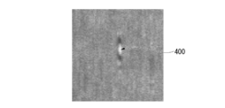
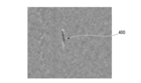
- An optical image 280 is formed, and the optical image 280 is captured by the line sensor camera 107 as an optical sensor. Then, from the reflected light intensity distribution image of the optical image 280 projected on the screen 102, the unevenness state of the outer peripheral surface 100d of the piston rod 100 is determined. For example, a concave defect 400 on the outer peripheral surface 100d as shown in FIG. 14 is detected.
- the optical image 280 of the screen 102 does not have light and dark.
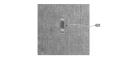
- the reflected light at the edge of the convex defect 401 becomes bright, and the intermediate portion of the convex defect 401 becomes brighter.
- the reflected light at the is darkened.
- the reflected light at the edge of the concave defect 400 becomes dark, and the light is reflected at the intermediate portion of the concave defect 400. Light becomes brighter.
- the unevenness state of the outer peripheral surface 100d of the piston rod 100 is determined from such a reflected light intensity distribution image.
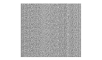
- FIG. 16 shows a reflected light intensity distribution image obtained by imaging the piston rod 100 including the concave defect 400 formed by buff peeling with the line sensor camera 107.
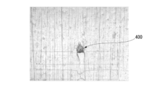
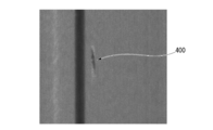
- FIG. 17 shows a microscope image including a concave defect 400 formed by buffing of the piston rod 100.
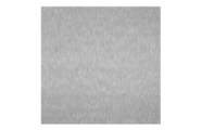
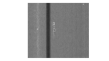
- FIG. 18 shows a reflected light intensity distribution image obtained by imaging the piston rod 100 including the convex defect 401 composed of a granular projection by the line sensor camera 107.
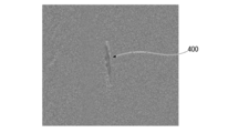
- FIG. 19 shows a microscopic image including a convex defect 401 formed of a granular projection of the piston rod 100.
- the irradiation light source is a laser light source
- laser speckle occurs on the screen
- the image data captured by the line sensor camera 107 contains speckle noise.
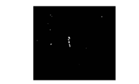
- Speckle noise is generated when coherent light such as laser light is projected onto a screen, reflected light of projections and depressions on the surface of the screen overlap and interfere with each other, and are amplified. Speckle noise is observed as a bright spot or a black spot on an image when the image is captured by an optical sensor such as the line sensor camera 107.
- the screen is vibrated.
- the screen is swung.
- a defect detection step SP8-4 by image processing is performed.
- image processing as shown in FIG. 22, first, image data captured by the line sensor camera 107 is used as an input image (step SPa1). Next, the input image is subjected to two-dimensional FFT processing to convert the image data into frequency domain data to obtain an FFT image from which an amplitude spectrum is extracted (step SPa2). On this amplitude spectrum, low frequency components are concentrated at the center, and become higher frequency components as the distance from the center increases.
- the amplitude spectrum is subjected to a high-pass filter process for removing a low-frequency component while leaving a high-frequency component with a high-pass filter (step SPa3).
- a high-pass filter process for removing a low-frequency component while leaving a high-frequency component with a high-pass filter
- the background information of the low frequency component disappears, and a result is obtained in which only the outline of the high frequency component is emphasized.
- the FFT image is subjected to a two-dimensional inverse FFT process (two-dimensional inverse Fourier transform process) to return the frequency domain data to image data, that is, a two-dimensional image (step SPa4).
- a two-dimensional image two-dimensional image
- the two-dimensional FFT processing, the high-pass filter processing, and the two-dimensional inverse FFT processing are performed.
- FIG. 24 it is possible to obtain a high-pass filter image in which the density information of the periodic vertical streak noise is lost and the outline of the defect 400 is enhanced.
- a smoothing process for reducing digital noise is performed by a smoothing filter (step SPa5).
- a smooth image with reduced digital noise is obtained from the high-pass filter image shown in FIG.
- the reference luminance information of the pixel (pixel) obtained in advance is compared with the luminance of each pixel obtained from the smoothed image in which the digital noise is reduced, and an image in which the difference between the reference luminance and the luminance of each pixel is a gray level value (Luminance difference image) is constituted (step SPa6).
- FIG. 26 is a luminance difference image of the smoothed image shown in FIG.
- FIG. 27 is a binarized image obtained by extracting a defect from the high luminance extracted image shown in FIG.
- defect determination is performed based on a predetermined labeling pixel area to generate a defect determination image (step SPa8). For example, a defect is determined when the labeling pixel area is 10 pixels or more.
- FIG. 28 is a defect determination image in which defects of the binarized image of FIG. 27 are extracted.
- the signal processing unit 231 shown in FIG. 6 uses the line sensor camera in the imaging / inspection step SP8-3 and the defect detection step SP8-4 shown in FIG. 5 of the surface inspection step SP8 shown in FIG.
- An evaluation step SP9 for determining whether the piston rod 100 is appropriate based on the imaging result and the image processing result of 107 is performed. That is, it is determined whether the piston rod 100 is good or defective based on the number of detected defects and the size of the defect. For example, if the number of defects is equal to or more than a predetermined number, it is determined to be defective, and even if the number of defects is less than this predetermined number, if there is a fatal defect whose defect size is larger than a predetermined value, it is determined to be defective. Then, other than these are judged as non-defective products.
- the transport device 260 has a branching unit 265 controlled by the signal processing unit 231.
- the transport device 260 transports the piston rod 100 determined to be non-defective by the inspection device 230 to the non-defective line 261 at the branching section 265 and transports the piston rod 100 to the assembly line via the non-defective line 261;
- a conveying step including a defective article conveying step SP11 for unloading the piston rod 100 to the defective article line 262 at the branching section 265 is performed. That is, the transport device 260 transports the piston rod 100, which is a component, to a different location in the transport process according to the evaluation result in the evaluation process.
- the irradiation light source is a laser light source
- laser speckle occurs on the screen
- speckle noise is included in image data captured by the optical sensor.
- the screen is vibrated in the device of Patent Document 1 described above, and the screen is rocked in the device of Patent Document 2, for example, image data when the screen is rocked As shown in FIG. 20, the speckle noise becomes a wave-shaped noise pattern, and it becomes difficult to remove the noise pattern by image processing.
- vibrations are generated, which may affect the measurement.
- the light beam 10 is irradiated on the outer peripheral surface 100d of the piston rod 100, which is the surface to be measured, and the light reflected on the outer peripheral surface 100d is projected on the screen 102 to form an optical image 280.
- the image is captured by the line sensor camera 107 as an optical sensor, the image is captured by the line sensor camera 107 while the screen 102 is continuously moved in one direction. This makes it easy to remove speckle noise by image processing, thereby reducing the influence of speckle noise. As described above, by reducing the influence of speckle noise, the measurement accuracy of the outer peripheral surface 100d of the piston rod 100 is improved.
- the outer surface 100d of the piston rod 100 which is the surface to be measured, is irradiated in a slit shape with the light beam 10 and the outer surface 100d of the piston rod 100 is moved relative to the outer surface 100d by relatively moving the light beam 10 and the outer surface 100d of the piston rod 100. Scan. Therefore, the measurement can be performed even when the surface to be measured is the outer peripheral surface 100d of the piston rod 100 as described above, which is a curved surface.
- the optical image 280 is captured in a linear shape using the line sensor camera 107 as an optical sensor that captures the optical image 280 projected on the screen 102. Therefore, the tact time of the measurement can be reduced.
- the cylindrical outer peripheral surface 102a of the screen 102 is composed of the Lambert scatterer 99. Therefore, the outer peripheral surface 102a can be made uniform, and the optical image 280 is stabilized. Therefore, the measurement accuracy of the outer peripheral surface 100d of the piston rod 100 is further improved.
- the outer peripheral surface 100d of the piston rod 100 which is the surface to be measured, has a convex shape
- the light beam 10 has a slit shape having a predetermined width and a predetermined thickness
- the light beam 10 has a convex shape.
- An optical image 280 is formed by irradiating along the outer peripheral surface 100d and projecting the reflected light reflected by the outer peripheral surface 100d of the convex piston rod 100 onto the screen 102.
- the reflected light of the light beam 10 is expanded by the outer peripheral surface 100d of the convex piston rod 100 and projected on the screen 102, so that the surface measurement accuracy of the outer peripheral surface 100d of the piston rod 100 is further improved.
- a part of the light beam 10 passes through the outer peripheral surface 100d of the piston rod 100, which is a convex surface to be measured, and is directly projected on the screen 102 to be used as reference light, and an optical image 280 specified by the reference light
- the surface condition of the outer peripheral surface 100d of the piston rod 100 is inspected on the basis of the reflected light intensity distribution at the measurement point. Therefore, since the position of the measurement location can be accurately specified, the measurement accuracy of the outer peripheral surface 100d of the piston rod 100 is further improved.
- the outer peripheral surface 100d of the piston rod 100 is mirror-finished by a processing step.
- the inspection process the light beam 10 is applied to the outer peripheral surface 100d of the piston rod 100, and the optical image 280 formed by projecting the light reflected on the outer peripheral surface 100d onto the screen 102 is formed by the line sensor camera 107 as an optical sensor. Take an image.
- the evaluation step the suitability of the component is determined based on the imaging result in the inspection step.
- the transfer step the piston rod 100 is transferred to a different place according to the evaluation result in the evaluation step.
- the piston rod 100 having the outer peripheral surface 100d as the surface to be measured is manufactured.
- the inspection accuracy in the inspection process is further improved as described above, so that the accuracy of sorting the non-defective product and the defective product of the piston rod 100 is further improved.
- the optical image 280 formed by irradiating the light beam 10 to the outer peripheral surface 100d of the mirror-like piston rod 100 and projecting the reflected light from the outer peripheral surface 100d onto the screen 102 by the image forming process is formed.
- a line sensor camera which is an optical sensor, converts the optical image 280 formed on the screen 102 in a state where the screen 102 is continuously moved in one direction at a constant speed irrespective of the width direction position of the optical image 280 by the imaging process. An image is taken by 107.
- the piston rod 100 is inspected. At this time, since the inspection accuracy is further improved as described above, the outer peripheral surface 100d of the piston rod 100 can be inspected more accurately.
- the irradiation unit 290 forms the light beam 10 in a slit shape and emits the light beam 10 toward the outer peripheral surface 100d of the piston rod 100, which is the measured surface of the component.
- the moving unit 270 relatively moves the light beam 10 irradiated from the irradiation unit 290 and the outer peripheral surface 100d of the piston rod 100.
- the screen drive motor 300 rotates the screen 102 on which the light reflected by the outer peripheral surface 100d of the piston rod 100 is projected to form the optical image 280.
- a line sensor camera 107 as an optical sensor captures an optical image 280.
- the screen drive motor 300 moves the screen 102 continuously in one direction. For this reason, it becomes easy to remove speckle noise by image processing, and it is possible to reduce the influence of speckle noise. As described above, by reducing the influence of speckle noise, the measurement accuracy of the outer peripheral surface 100d of the piston rod 100 is improved.
- the line sensor camera 107 since the line sensor camera 107 is used, various types of surfaces to be measured are used. It is possible to scan the surface. For example, as shown in a modification shown in FIG. 29, while the plane 310 of the part 311 whose surface to be measured consists of the plane 310 is slid in the same plane by the moving unit 312 including the slide moving mechanism, the reflected light is reflected by the plane 310. Light may be projected onto the screen 102 to form an optical image 315, and the optical image 315 may be captured by the line sensor camera 107. Also at this time, the line sensor camera 107 captures an image in synchronization with the moving unit 312.
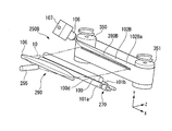
- the measuring device 250A has a screen 102A formed in a belt-like endless ring having a constant thickness.
- the screen 102A is wound around two rotating rollers 320 and 321.
- Each of the two rotating rollers 320 and 321 has a cylindrical outer peripheral surface, and is supported so as to be rotatable around a cylindrical central axis on the outer peripheral surface.
- These rotation rollers 320 and 321 have their central axes parallel to the X axis and are aligned with each other in the X direction.
- the number of the rotating rollers around which the screen 102A is wound may be at least two, and may be three or more. Also in this case, all the rotating rollers make the central axis parallel.
- the measuring device 250A of the second embodiment is provided with a tensioner 331 having a flat pressing surface 330 at a position between the rotating rollers 320 and 321 in the Y direction.
- the tensioner 331 is a plate-like member having a substantially trapezoidal cross section in a plane orthogonal to the longitudinal direction.
- the tensioner 331 has a flat pressing surface 330, a flat back surface 332 parallel to the pressing surface 330, and a pair of connecting surfaces 333 and 334 connecting these.
- the pressing surface 330 has a length perpendicular to the longitudinal direction shorter than the back surface 332, and the center position in the direction perpendicular to the longitudinal direction is aligned with the back surface 332.
- One connection surface 333 connects one end edge of the pressing surface 330 in the direction orthogonal to the longitudinal direction and one end edge of the back surface 332 in the direction orthogonal to the longitudinal direction.
- the other connection surface 334 connects the other end of the pressing surface 330 in the direction orthogonal to the longitudinal direction and the other end of the back surface 332 in the direction orthogonal to the longitudinal direction.
- Each of the pair of connection surfaces 333 and 334 has a shape of a part of a cylindrical surface, and is curved so as to be convex toward the outside of the tensioner 331.
- the tensioner 331 is arranged such that the pressing surface 330 is arranged in parallel with a plane including the central axis of the two rotating rollers 320 and 321, that is, the XY plane, and is arranged at an intermediate position between the two rotating rollers 320 and 321 in the Y direction. ing.
- the tensioner 331 presses the ring-shaped screen 102A from the inside to the outside of the ring with the pressing surface 330.
- the projection surface 102Aa that is a plane following the pressing surface 330 of the tensioner 331 is formed on the screen 102A.
- the projection surface 102Aa extends in parallel with the XY plane.
- One of the two rotating rollers 320 and 321 is driven by a screen driving motor (not shown). Then, one of the rotating rollers 320 and 321 is driven to rotate the screen 102A and the other rotating roller. As a result, the portion of the screen 102A that forms the projection surface 102Aa continuously moves in the Y direction. In other words, the portion of the screen 102A that projects the optical image 280A on the projection surface 102Aa is continuously shifted in one direction with respect to the optical image 280A projected at a fixed position.
- An irradiation unit 290 similar to the first embodiment forms the light beam 10 in a slit shape having a predetermined width W ⁇ a predetermined thickness t1 and is rotated by a moving unit 270 similar to the first embodiment.
- the screen 102A emits the light toward the outer peripheral surface 100d, which is the measured surface of the piston 100
- the screen 102A projects the reflected light from the outer peripheral surface 100d of the piston rod 100 onto a flat projection surface 102Aa to form an optical image 280A.
- An image 280A is captured by the same line sensor camera 107 as in the first embodiment.
- the optical image 280A linearly extends in the X direction orthogonal to the Y direction, which is the moving direction of the portion forming the projection surface 102Aa of the screen 102A, as in the first embodiment, and the entire surface of the screen 102A is covered. It is projected on the projection surface 102Aa.
- the line sensor camera 107 captures the optical image 280A formed on the projection surface 102Aa of the screen 102A in a linear shape parallel to the X axis, as in the first embodiment.
- the imaging by the line sensor camera 107 which is an optical sensor, is executed while the screen 102A is continuously moved in one direction.
- the imaging by the line sensor camera 107 is executed by continuously moving the screen 102A at a constant speed regardless of the width direction position of the optical image 280A.
- the portion of the screen 102A that projects the optical image 280A moves in a direction orthogonal to the width direction of the optical image 280A.
- the projection surface 102Aa can be flattened.
- the optical image 280A is unlikely to be distorted, so that the measurement accuracy of the outer peripheral surface 100d of the piston rod 100 is further improved.
- the measuring device 250B has a screen 102B formed in a belt-like endless ring having a constant thickness.
- the screen 102B is wound around two rotating rollers 350 and 351.
- Each of the two rotating rollers 350 and 351 has a cylindrical outer peripheral surface, and is supported so as to be rotatable about a cylindrical central axis on the outer peripheral surface.
- These rotating rollers 350 and 351 have their central axes parallel to the Y axis, and are aligned with each other in the Y direction and with each other in the Z direction.
- the number of rotating rollers around which the screen 102B is wound may be at least two, and may be three or more. Also in this case, all the rotating rollers make the central axis parallel.
- the measuring device 250B of the third embodiment forms a flat projection surface 102Ba between the rotating rollers 350 and 351 on the screen 102B.
- the projection surface 120Ba extends in parallel with the XY plane.
- One of the two rotating rollers 350 and 351 is driven by a screen drive motor (not shown). Then, one of the rotating rollers 350 and 351 is driven to rotate the screen 102B and the other rotating roller. As a result, the portion of the screen 102B that forms the projection surface 102Ba moves continuously in the X direction. In other words, the portion of the screen 102B where the optical image 280B is projected on the projection surface 102Ba is continuously shifted in one direction with respect to the optical image 280B projected at a fixed position.
- An irradiation unit 290 similar to the first embodiment forms the light beam 10 in a slit shape having a predetermined width W ⁇ a predetermined thickness t1 and is rotated by a moving unit 270 similar to the first embodiment.
- the light is emitted toward the outer peripheral surface 100d which is the surface to be measured 100.
- the screen 102B projects the reflected light from the outer peripheral surface 100d of the piston rod 100 onto the flat projection surface 102Ba to form an optical image 280B.
- This optical image 280B is captured by the same line sensor camera 107 as in the first embodiment.
- the optical image 280B extends linearly in the direction along the movement direction of the portion forming the projection surface 102Ba of the screen 102B, that is, in the X direction.
- the optical image 280B formed in the image is captured in a linear shape parallel to the X axis.
- the imaging by the line sensor camera 107 which is an optical sensor, is executed while the screen 102B is continuously moved in one direction.
- the imaging by the line sensor camera 107 is executed by continuously moving the screen 102B at a constant speed regardless of the width direction position of the optical image 280B.
- the portion of the screen 102B that projects the optical image 280B moves in the width direction of the optical image 280B.
- the projection surface 102Ba can be flattened.
- the optical image 280B is unlikely to be distorted, so that the measurement accuracy of the outer peripheral surface 101a of the piston rod 101 is further improved.
- a first aspect of the embodiment described above is to irradiate a coherent light beam to a surface to be measured, project light reflected on the surface to be measured onto a screen, form an optical image, and form the optical image.
- a surface measuring method for imaging by an optical sensor wherein the imaging by the optical sensor is performed while the screen is continuously moved in one direction. Thereby, the influence of speckle noise can be reduced, and the measurement accuracy is improved.
- the screen is continuously moved at a constant speed regardless of the width direction position of the optical image.
- the moving speed of the screen is constant irrespective of the position in the width direction of the optical image, the noise pattern becomes a vertical streak, and the measurement accuracy is improved.
- the screen is formed in a cylindrical shape and continuously rotated. Thereby, the surface movement of the screen is stabilized, and the inspection accuracy is improved.
- the light beam is emitted to the surface to be measured in a slit shape, and the surface to be measured is scanned by relatively moving the surface to be measured and the light beam. .
- measurement can be performed even if the surface to be measured is a curved surface.
- the optical sensor is a line sensor, and captures the optical image in a linear shape. Thereby, the tact time of the measurement can be reduced.
- the screen has a cylindrical outer peripheral surface formed of a diffuse reflector. Thereby, the surface of the screen can be made uniform, and the optical image is stabilized, so that the measurement accuracy is improved.
- the screen is formed in a belt-like and endless loop, wound around at least two rotating rollers, and the screen is rotated by driving the rotating rollers to form one screen. Move continuously in the direction. Thereby, the projection surface of the screen becomes flat and the optical image is hardly distorted, so that the measurement accuracy can be improved.
- the surface to be measured is convex
- the light beam has a slit shape having a predetermined width and a predetermined thickness
- the light beam has a convex shape.
- the optical image is formed by irradiating light along the surface and projecting the reflected light reflected by the convex surface to be measured onto the screen. Thereby, the reflected light of the light beam is enlarged by the convex surface to be measured, so that the surface measurement accuracy is improved.
- a part of the light beam passes through the convex surface to be measured and is directly projected on the screen to serve as reference light, and the light beam is specified by the reference light.
- the surface condition of the surface to be measured is inspected based on the reflected light intensity distribution at the measurement point of the optical image. Thereby, the position of the measurement point can be specified, and the measurement accuracy is improved.
- a tenth aspect is a method for manufacturing a component having a surface to be measured, a processing step of mirror-finishing the surface to be measured, and irradiating a coherent light beam to the surface to be measured, and reflecting the light from the surface to be measured.
- the screen is continuously moved at a constant speed regardless of the width direction position of the optical image.
- the moving speed of the screen is constant irrespective of the position in the width direction of the optical image, the noise pattern becomes a vertical streak, and the inspection accuracy is improved.
- the screen is formed in a cylindrical shape and is continuously rotated. Thereby, the surface movement of the screen is stabilized, and the inspection accuracy is improved.
- the surface to be measured is convex
- the light beam has a slit shape having a predetermined width and a predetermined thickness
- the light beam has a convex shape.
- the optical image is formed by irradiating light along the surface and projecting the reflected light reflected by the convex surface to be measured onto the screen.
- the reflected light of the light beam is enlarged by the convex surface to be measured, so that the inspection accuracy is improved.
- a fourteenth aspect is the thirteenth aspect, wherein a part of the light beam passes through the convex surface to be measured and is directly projected on the screen as reference light, and the light beam is specified by the reference light.
- the surface condition of the surface to be measured is inspected based on the reflected light intensity distribution at the measurement point of the optical image. Thereby, the position of the measurement point can be specified, and the inspection accuracy is improved.
- the screen is formed in a belt-like and endless loop, wound around at least two rotating rollers, and the screen is rotated by rotating the rotating rollers to form one screen. Move continuously in the direction. Thereby, the projection surface of the screen becomes flat and the optical image is hardly distorted, so that the inspection accuracy is improved.
- a sixteenth aspect is a method for inspecting a component having a mirror-like surface to be measured, which irradiates a coherent light beam to the surface to be measured, and projects light reflected by the surface to be measured onto a screen.
- the screen is formed in a cylindrical shape and continuously rotated. Thereby, the surface movement of the screen is stabilized, and the inspection accuracy is improved.
- the surface to be measured is convex
- the light beam has a slit shape having a predetermined width and a predetermined thickness
- the light beam has a convex shape.
- the optical image is formed by irradiating light along the surface and projecting the reflected light reflected by the convex surface to be measured onto the screen.
- the reflected light of the light beam is expanded by the convex surface to be measured, and the inspection accuracy is improved.
- the screen is formed in a belt-like and endless loop, wound around at least two rotating rollers, and the screen is rotated by rotating the rotating rollers to form one screen. Move continuously in the direction. Thereby, the projection surface of the screen becomes flat and the optical image is hardly distorted, so that the inspection accuracy can be improved.
- a twentieth aspect is a measuring apparatus for measuring a measured surface of a component, wherein the irradiating unit forms a coherent light beam in a slit shape and emits the beam toward the measured surface of the component, and irradiates from the irradiating unit.
- a moving unit for relatively moving the light beam and the measured surface of the component, a screen on which reflected light reflected by the measured surface of the component is projected to form an optical image, and
- An optical sensor for imaging and a drive source for continuously moving the screen in one direction are provided. Thereby, the influence of speckle noise can be reduced, and the measurement accuracy is improved.
Landscapes
- Physics & Mathematics (AREA)
- General Physics & Mathematics (AREA)
- Chemical & Material Sciences (AREA)
- Health & Medical Sciences (AREA)
- Life Sciences & Earth Sciences (AREA)
- Analytical Chemistry (AREA)
- Biochemistry (AREA)
- General Health & Medical Sciences (AREA)
- Immunology (AREA)
- Pathology (AREA)
- Signal Processing (AREA)
- Engineering & Computer Science (AREA)
- Computer Vision & Pattern Recognition (AREA)
- Length Measuring Devices By Optical Means (AREA)
- Investigating Materials By The Use Of Optical Means Adapted For Particular Applications (AREA)
Abstract
L'invention concerne un procédé de mesure de surface selon lequel un faisceau de lumière cohérente (10) est projeté sur une surface à mesurer (100d), la lumière réfléchie qui a été réfléchie par la surface à mesurer (100d) est projetée sur un écran (102) et formée en une image optique (280), et l'image optique (280) est imagée par un capteur optique (107) tandis que l'écran (102) est déplacé en continu dans une seule direction.
Priority Applications (3)
| Application Number | Priority Date | Filing Date | Title |
|---|---|---|---|
| US17/272,672 US11781861B2 (en) | 2018-09-06 | 2019-08-14 | Surface measurement method, component manufacturing method, component inspection method, and component measurement device |
| JP2020541100A JP7069328B2 (ja) | 2018-09-06 | 2019-08-14 | 表面測定方法、部品の製造方法、部品の検査方法および部品の測定装置 |
| CN201980057651.5A CN112840206B (zh) | 2018-09-06 | 2019-08-14 | 表面测量方法、零件的制造方法、零件的检查方法以及零件的测量装置 |
Applications Claiming Priority (2)
| Application Number | Priority Date | Filing Date | Title |
|---|---|---|---|
| JP2018167261 | 2018-09-06 | ||
| JP2018-167261 | 2018-09-06 |
Publications (1)
| Publication Number | Publication Date |
|---|---|
| WO2020049971A1 true WO2020049971A1 (fr) | 2020-03-12 |
Family
ID=69722907
Family Applications (1)
| Application Number | Title | Priority Date | Filing Date |
|---|---|---|---|
| PCT/JP2019/031930 Ceased WO2020049971A1 (fr) | 2018-09-06 | 2019-08-14 | Procédé de mesure de surface, procédé de fabrication de composant, procédé d'inspection de composant et dispositif de mesure de composant |
Country Status (4)
| Country | Link |
|---|---|
| US (1) | US11781861B2 (fr) |
| JP (1) | JP7069328B2 (fr) |
| CN (1) | CN112840206B (fr) |
| WO (1) | WO2020049971A1 (fr) |
Cited By (3)
| Publication number | Priority date | Publication date | Assignee | Title |
|---|---|---|---|---|
| CN112881428A (zh) * | 2021-01-20 | 2021-06-01 | 苏州协同创新智能制造装备有限公司 | 一种基于激光测距的曲面屏幕边缘外弧缺陷检测的方法 |
| JP2023160096A (ja) * | 2022-04-21 | 2023-11-02 | 株式会社リコー | 表面欠陥検出装置および表面欠陥検出方法 |
| KR20240058651A (ko) * | 2022-10-26 | 2024-05-03 | (주)캠시스 | 이물 등급화를 위한 영역 추출 방법과 이를 이용한 카메라 검사 방법 및 시스템 |
Families Citing this family (1)
| Publication number | Priority date | Publication date | Assignee | Title |
|---|---|---|---|---|
| CN121067726A (zh) * | 2025-09-09 | 2025-12-05 | 科德数控股份有限公司 | 一种用于高速旋转叶片长度测量的设备及方法 |
Citations (8)
| Publication number | Priority date | Publication date | Assignee | Title |
|---|---|---|---|---|
| JP2002139447A (ja) * | 2000-08-03 | 2002-05-17 | Nkk Corp | 表面検査装置及び微小凹凸欠陥の無い鋼板の製造方法 |
| JP2002296514A (ja) * | 2001-03-30 | 2002-10-09 | Ricoh Co Ltd | レーザ光源装置 |
| JP2003083722A (ja) * | 2001-09-14 | 2003-03-19 | Toto Ltd | レーザー投影による形状計測方法および装置 |
| JP2006343663A (ja) * | 2005-06-10 | 2006-12-21 | Sony Corp | 画像投影装置及びこれに用いるスクリーン |
| JP2012008078A (ja) * | 2010-06-28 | 2012-01-12 | Yokogawa Electric Corp | 欠陥検査装置 |
| JP2014163974A (ja) * | 2013-02-21 | 2014-09-08 | Seiko Epson Corp | 光源装置およびプロジェクター |
| WO2014167672A1 (fr) * | 2013-04-10 | 2014-10-16 | パイオニア株式会社 | Dispositif d'écran |
| JP2015087593A (ja) * | 2013-10-31 | 2015-05-07 | アルプス電気株式会社 | 画像投影装置 |
Family Cites Families (20)
| Publication number | Priority date | Publication date | Assignee | Title |
|---|---|---|---|---|
| GB586937A (en) * | 1944-09-19 | 1947-04-08 | United Dairies Ltd | Improvements in or relating to apparatus for detecting the presence of foreign bodies in transparent vessels |
| GB750911A (en) * | 1953-05-29 | 1956-06-20 | Nat Res Dev | Optical projection system and apparatus |
| US3930994A (en) * | 1973-10-03 | 1976-01-06 | Sunkist Growers, Inc. | Method and means for internal inspection and sorting of produce |
| US4853777A (en) * | 1987-07-07 | 1989-08-01 | Ashland Oil, Inc. | Method for evaluating smooth surfaces |
| JP3099462B2 (ja) * | 1991-09-30 | 2000-10-16 | 凸版印刷株式会社 | 円筒面検査方法及びその装置 |
| WO1993012615A1 (fr) * | 1991-12-19 | 1993-06-24 | The United States Of America, Represented By The Secretary, United States Department Of Commerce | Procede et appareil permettant d'evaluer le lisse d'une surface par recours a une energie reflechie |
| JP3386269B2 (ja) * | 1995-01-25 | 2003-03-17 | 株式会社ニュークリエイション | 光学検査装置 |
| JP3007849B2 (ja) * | 1996-06-21 | 2000-02-07 | 松下電工株式会社 | 物体表面の形状検出方法及び形状検出装置 |
| US5880843A (en) * | 1997-09-03 | 1999-03-09 | Vitro Flotado, S.A. De C.V. | Apparatus and method for determining the optical distortion of a transparent substrate |
| US6323984B1 (en) * | 2000-10-11 | 2001-11-27 | Silicon Light Machines | Method and apparatus for reducing laser speckle |
| CN1756948B (zh) * | 2003-02-28 | 2010-05-26 | 皇家飞利浦电子股份有限公司 | 用于检查表面的散射计和方法 |
| JP4307206B2 (ja) | 2003-09-30 | 2009-08-05 | パナソニック株式会社 | ディスプレイ装置 |
| US7362450B2 (en) * | 2005-12-23 | 2008-04-22 | Xerox Corporation | Specular surface flaw detection |
| WO2009021123A1 (fr) * | 2007-08-07 | 2009-02-12 | Tsi Incorporated | Dispositif de mesure de la concentration massique d'un aérosol à ségrégation par taille |
| FR2932898B1 (fr) * | 2008-06-23 | 2010-08-20 | Bakery | Dispositif monolampe pour projection sur 360°= |
| US8817274B2 (en) * | 2009-06-23 | 2014-08-26 | Bongmin Seo | Thickness variation measuring device, system using same, surface microscope using same, thickness variation measuring method, and surface image acquiring method using same |
| CN102893142A (zh) * | 2010-05-25 | 2013-01-23 | 二宫宝石株式会社 | 用于测量散射特性的装置、用于宝石的散射光的色彩测量装置、用于测量宝石的亮度的装置以及用于测量宝石的发光分布的装置 |
| US10281408B2 (en) * | 2016-04-12 | 2019-05-07 | Nippon Steel & Sumitomo Metal Corporation | Inspection object imaging apparatus, inspection object imaging method, surface inspection apparatus, and surface inspection method |
| CN106198563B (zh) * | 2016-08-04 | 2020-05-12 | 中国乐凯集团有限公司 | 一种薄膜瑕疵在线监测装置及其方法 |
| FR3087891B1 (fr) * | 2018-10-24 | 2020-11-20 | Entpe | Dispositif optique pour la mesure des proprietes optiques des materiaux. |
-
2019
- 2019-08-14 JP JP2020541100A patent/JP7069328B2/ja active Active
- 2019-08-14 US US17/272,672 patent/US11781861B2/en active Active
- 2019-08-14 CN CN201980057651.5A patent/CN112840206B/zh active Active
- 2019-08-14 WO PCT/JP2019/031930 patent/WO2020049971A1/fr not_active Ceased
Patent Citations (8)
| Publication number | Priority date | Publication date | Assignee | Title |
|---|---|---|---|---|
| JP2002139447A (ja) * | 2000-08-03 | 2002-05-17 | Nkk Corp | 表面検査装置及び微小凹凸欠陥の無い鋼板の製造方法 |
| JP2002296514A (ja) * | 2001-03-30 | 2002-10-09 | Ricoh Co Ltd | レーザ光源装置 |
| JP2003083722A (ja) * | 2001-09-14 | 2003-03-19 | Toto Ltd | レーザー投影による形状計測方法および装置 |
| JP2006343663A (ja) * | 2005-06-10 | 2006-12-21 | Sony Corp | 画像投影装置及びこれに用いるスクリーン |
| JP2012008078A (ja) * | 2010-06-28 | 2012-01-12 | Yokogawa Electric Corp | 欠陥検査装置 |
| JP2014163974A (ja) * | 2013-02-21 | 2014-09-08 | Seiko Epson Corp | 光源装置およびプロジェクター |
| WO2014167672A1 (fr) * | 2013-04-10 | 2014-10-16 | パイオニア株式会社 | Dispositif d'écran |
| JP2015087593A (ja) * | 2013-10-31 | 2015-05-07 | アルプス電気株式会社 | 画像投影装置 |
Cited By (4)
| Publication number | Priority date | Publication date | Assignee | Title |
|---|---|---|---|---|
| CN112881428A (zh) * | 2021-01-20 | 2021-06-01 | 苏州协同创新智能制造装备有限公司 | 一种基于激光测距的曲面屏幕边缘外弧缺陷检测的方法 |
| JP2023160096A (ja) * | 2022-04-21 | 2023-11-02 | 株式会社リコー | 表面欠陥検出装置および表面欠陥検出方法 |
| KR20240058651A (ko) * | 2022-10-26 | 2024-05-03 | (주)캠시스 | 이물 등급화를 위한 영역 추출 방법과 이를 이용한 카메라 검사 방법 및 시스템 |
| KR102737995B1 (ko) | 2022-10-26 | 2024-12-04 | (주)캠시스 | 이물 등급화를 위한 영역 추출 방법과 이를 이용한 카메라 검사 방법 및 시스템 |
Also Published As
| Publication number | Publication date |
|---|---|
| US11781861B2 (en) | 2023-10-10 |
| CN112840206B (zh) | 2024-07-05 |
| JP7069328B2 (ja) | 2022-05-17 |
| US20210270603A1 (en) | 2021-09-02 |
| CN112840206A (zh) | 2021-05-25 |
| JPWO2020049971A1 (ja) | 2021-08-26 |
Similar Documents
| Publication | Publication Date | Title |
|---|---|---|
| JP7069328B2 (ja) | 表面測定方法、部品の製造方法、部品の検査方法および部品の測定装置 | |
| US10261028B2 (en) | Device for optically inspecting a surface of a sample | |
| JP6951439B2 (ja) | 表面検査方法、表面検査装置および製品の製造方法 | |
| JP3914500B2 (ja) | 欠陥検査装置 | |
| JP2004279367A (ja) | 表面欠陥検査装置及び制御プログラム記録媒体 | |
| JP4426386B2 (ja) | 表面欠陥検査装置、表面欠陥検査方法、その方法をコンピュータに実行させるプログラム | |
| JP5005218B2 (ja) | 検査装置および検査方法 | |
| JP6393663B2 (ja) | 表面検査装置 | |
| JPH07239304A (ja) | 表面層欠陥検出装置 | |
| JP4859127B2 (ja) | 円筒体自動検査方法 | |
| JP4903658B2 (ja) | 表面検査方法及び表面検査装置 | |
| JP2002148029A (ja) | 円筒状被検物の表面凹凸検査装置及び方法 | |
| JP3348133B2 (ja) | ディスク外観検査方法及びその装置 | |
| JP2016511829A (ja) | 領域の表面精度の定量的測定のための方法及び装置 | |
| JPH0868760A (ja) | 表面層欠陥検出装置 | |
| JP2006258663A (ja) | 表面欠陥検査装置 | |
| JP2025068306A (ja) | 表面欠陥検査装置および表面欠陥検査方法 | |
| JP2001050905A (ja) | 円筒体欠陥検査装置 | |
| JP7621789B2 (ja) | 検査装置、検査用照明装置、検査方法、および物品の製造方法 | |
| JP2021196189A (ja) | 検査装置及び検査方法 | |
| JP2004156932A (ja) | 表面検査装置 | |
| JPH06160723A (ja) | 暗視野照明装置 | |
| JP2003240729A (ja) | 表面検査方法及び装置 | |
| JP6500876B2 (ja) | 摺動装置 | |
| JPH0637709U (ja) | シリンダブロックのボアの粗残り検査装置 |
Legal Events
| Date | Code | Title | Description |
|---|---|---|---|
| 121 | Ep: the epo has been informed by wipo that ep was designated in this application |
Ref document number: 19857803 Country of ref document: EP Kind code of ref document: A1 |
|
| ENP | Entry into the national phase |
Ref document number: 2020541100 Country of ref document: JP Kind code of ref document: A |
|
| NENP | Non-entry into the national phase |
Ref country code: DE |
|
| 122 | Ep: pct application non-entry in european phase |
Ref document number: 19857803 Country of ref document: EP Kind code of ref document: A1 |