WO2020050157A1 - リーン車両 - Google Patents
リーン車両 Download PDFInfo
- Publication number
- WO2020050157A1 WO2020050157A1 PCT/JP2019/034057 JP2019034057W WO2020050157A1 WO 2020050157 A1 WO2020050157 A1 WO 2020050157A1 JP 2019034057 W JP2019034057 W JP 2019034057W WO 2020050157 A1 WO2020050157 A1 WO 2020050157A1
- Authority
- WO
- WIPO (PCT)
- Prior art keywords
- frame
- axis
- body frame
- link
- vehicle
- Prior art date
- Legal status (The legal status is an assumption and is not a legal conclusion. Google has not performed a legal analysis and makes no representation as to the accuracy of the status listed.)
- Ceased
Links
Images




Classifications
-
- B—PERFORMING OPERATIONS; TRANSPORTING
- B62—LAND VEHICLES FOR TRAVELLING OTHERWISE THAN ON RAILS
- B62K—CYCLES; CYCLE FRAMES; CYCLE STEERING DEVICES; RIDER-OPERATED TERMINAL CONTROLS SPECIALLY ADAPTED FOR CYCLES; CYCLE AXLE SUSPENSIONS; CYCLE SIDE-CARS, FORECARS, OR THE LIKE
- B62K5/00—Cycles with handlebars, equipped with three or more main road wheels
- B62K5/08—Cycles with handlebars, equipped with three or more main road wheels with steering devices acting on two or more wheels
-
- B—PERFORMING OPERATIONS; TRANSPORTING
- B62—LAND VEHICLES FOR TRAVELLING OTHERWISE THAN ON RAILS
- B62K—CYCLES; CYCLE FRAMES; CYCLE STEERING DEVICES; RIDER-OPERATED TERMINAL CONTROLS SPECIALLY ADAPTED FOR CYCLES; CYCLE AXLE SUSPENSIONS; CYCLE SIDE-CARS, FORECARS, OR THE LIKE
- B62K11/00—Motorcycles, engine-assisted cycles or motor scooters with one or two wheels
- B62K11/02—Frames
- B62K11/04—Frames characterised by the engine being between front and rear wheels
-
- B—PERFORMING OPERATIONS; TRANSPORTING
- B62—LAND VEHICLES FOR TRAVELLING OTHERWISE THAN ON RAILS
- B62K—CYCLES; CYCLE FRAMES; CYCLE STEERING DEVICES; RIDER-OPERATED TERMINAL CONTROLS SPECIALLY ADAPTED FOR CYCLES; CYCLE AXLE SUSPENSIONS; CYCLE SIDE-CARS, FORECARS, OR THE LIKE
- B62K19/00—Cycle frames
- B62K19/18—Joints between frame members
- B62K19/24—Screwed joints
-
- B—PERFORMING OPERATIONS; TRANSPORTING
- B62—LAND VEHICLES FOR TRAVELLING OTHERWISE THAN ON RAILS
- B62K—CYCLES; CYCLE FRAMES; CYCLE STEERING DEVICES; RIDER-OPERATED TERMINAL CONTROLS SPECIALLY ADAPTED FOR CYCLES; CYCLE AXLE SUSPENSIONS; CYCLE SIDE-CARS, FORECARS, OR THE LIKE
- B62K19/00—Cycle frames
- B62K19/30—Frame parts shaped to receive other cycle parts or accessories
- B62K19/32—Steering heads
-
- B—PERFORMING OPERATIONS; TRANSPORTING
- B62—LAND VEHICLES FOR TRAVELLING OTHERWISE THAN ON RAILS
- B62K—CYCLES; CYCLE FRAMES; CYCLE STEERING DEVICES; RIDER-OPERATED TERMINAL CONTROLS SPECIALLY ADAPTED FOR CYCLES; CYCLE AXLE SUSPENSIONS; CYCLE SIDE-CARS, FORECARS, OR THE LIKE
- B62K25/00—Axle suspensions
- B62K25/04—Axle suspensions for mounting axles resiliently on cycle frame or fork
- B62K25/06—Axle suspensions for mounting axles resiliently on cycle frame or fork with telescopic fork, e.g. including auxiliary rocking arms
- B62K25/08—Axle suspensions for mounting axles resiliently on cycle frame or fork with telescopic fork, e.g. including auxiliary rocking arms for front wheel
-
- B—PERFORMING OPERATIONS; TRANSPORTING
- B62—LAND VEHICLES FOR TRAVELLING OTHERWISE THAN ON RAILS
- B62K—CYCLES; CYCLE FRAMES; CYCLE STEERING DEVICES; RIDER-OPERATED TERMINAL CONTROLS SPECIALLY ADAPTED FOR CYCLES; CYCLE AXLE SUSPENSIONS; CYCLE SIDE-CARS, FORECARS, OR THE LIKE
- B62K5/00—Cycles with handlebars, equipped with three or more main road wheels
- B62K5/02—Tricycles
- B62K5/027—Motorcycles with three wheels
-
- B—PERFORMING OPERATIONS; TRANSPORTING
- B62—LAND VEHICLES FOR TRAVELLING OTHERWISE THAN ON RAILS
- B62K—CYCLES; CYCLE FRAMES; CYCLE STEERING DEVICES; RIDER-OPERATED TERMINAL CONTROLS SPECIALLY ADAPTED FOR CYCLES; CYCLE AXLE SUSPENSIONS; CYCLE SIDE-CARS, FORECARS, OR THE LIKE
- B62K5/00—Cycles with handlebars, equipped with three or more main road wheels
- B62K5/02—Tricycles
- B62K5/05—Tricycles characterised by a single rear wheel
-
- B—PERFORMING OPERATIONS; TRANSPORTING
- B62—LAND VEHICLES FOR TRAVELLING OTHERWISE THAN ON RAILS
- B62K—CYCLES; CYCLE FRAMES; CYCLE STEERING DEVICES; RIDER-OPERATED TERMINAL CONTROLS SPECIALLY ADAPTED FOR CYCLES; CYCLE AXLE SUSPENSIONS; CYCLE SIDE-CARS, FORECARS, OR THE LIKE
- B62K5/00—Cycles with handlebars, equipped with three or more main road wheels
- B62K5/02—Tricycles
- B62K5/06—Frames for tricycles
-
- B—PERFORMING OPERATIONS; TRANSPORTING
- B62—LAND VEHICLES FOR TRAVELLING OTHERWISE THAN ON RAILS
- B62K—CYCLES; CYCLE FRAMES; CYCLE STEERING DEVICES; RIDER-OPERATED TERMINAL CONTROLS SPECIALLY ADAPTED FOR CYCLES; CYCLE AXLE SUSPENSIONS; CYCLE SIDE-CARS, FORECARS, OR THE LIKE
- B62K5/00—Cycles with handlebars, equipped with three or more main road wheels
- B62K5/10—Cycles with handlebars, equipped with three or more main road wheels with means for inwardly inclining the vehicle body on bends
-
- B—PERFORMING OPERATIONS; TRANSPORTING
- B62—LAND VEHICLES FOR TRAVELLING OTHERWISE THAN ON RAILS
- B62K—CYCLES; CYCLE FRAMES; CYCLE STEERING DEVICES; RIDER-OPERATED TERMINAL CONTROLS SPECIALLY ADAPTED FOR CYCLES; CYCLE AXLE SUSPENSIONS; CYCLE SIDE-CARS, FORECARS, OR THE LIKE
- B62K5/00—Cycles with handlebars, equipped with three or more main road wheels
- B62K2005/001—Suspension details for cycles with three or more main road wheels
Definitions
- the present invention relates to a lean vehicle including a leanable vehicle body frame, and a left front wheel and a right front wheel arranged so as to be aligned in the left-right direction of the vehicle body frame.
- Patent Documents 1 and 2 disclose a lean vehicle that has a right front wheel, a left front wheel, and one rear wheel, and inclines to the right to turn right and turns to the left to turn left.
- This lean vehicle has a parallelo link mechanism that changes the relative positions of the right front wheel and the left front wheel in the up-down direction of the body frame according to the inclination of the body frame.
- the parallelo link mechanism is supported by a link support portion so as to be swingable about a link axis extending substantially in the front-rear direction.
- the parallelo link mechanism includes an upper cross member supported by the link support portion so as to be able to swing around the link axis at the middle portion, and a lower cross member supported by the link support portion so as to be able to swing around the link axis at the middle portion.
- a right side member swingably connected to a right portion of the upper cross member and a right portion of the lower cross member to support an upper portion of the right shock absorber, and swings to a left portion of the upper cross member and a left portion of the lower cross member.
- a left side member operatively connected to support an upper portion of the left shock absorber.
- the link support is supported by the body frame.
- the link support is welded to the rigid right and left frames supporting the power unit.
- the right frame is welded to the right part of the link support, and the left frame is welded to the left of the link support.
- the right frame and the left frame are welded to a single thick frame, and the link support is welded to the thick frame.
- the right frame and the left frame are formed to extend to the link support portion, and furthermore, the front end of the right frame is bent leftward to reach the right portion of the link support portion, and the front end of the left frame is It is bent to the right to reach the left part of the link support.
- the shape of the right frame and the shape of the left frame there are great restrictions on the shape of the right frame and the shape of the left frame.
- the size of the lean vehicle tends to increase in order to secure a space for providing a single thick frame.
- the link support has an upper boss and a lower boss.
- An upper shaft member for supporting the upper cross member is provided at the tip of the upper boss.
- the upper shaft member supports the upper cross member so as to be swingable around the upper middle axis.
- a lower shaft member that supports the lower cross member is provided on the distal end surface of the lower boss.
- the lower shaft member supports the lower cross member so as to be swingable around a lower intermediate axis. Since the central axis of the upper shaft member is the upper middle leaning axis of the upper cross member, strict shape accuracy is required for the upper boss portion. Since the center axis of the lower shaft member is the lower intermediate leaning axis of the lower cross member, the lower boss is required to have strict shape accuracy.
- the heat capacity of the upper boss portion and the lower boss portion is ensured by increasing the longitudinal length of the upper boss portion and the lower boss portion, and the upper boss portion is welded. And the lower boss is hardly heated. Further, in the lean vehicle of Patent Literature 2, the link support portion and the vehicle body frame are welded at locations away from the upper boss portion and the lower boss portion.
- the link support is welded to the body frame while ensuring the accuracy of the upper boss and the lower boss, the design of the body frame and the link support is greatly restricted. Therefore, the present inventor hoped that if the link support could be attached to the vehicle body frame without welding, the degree of freedom in design would be increased.
- an object of the present invention is to provide a front two-wheel lean vehicle that can be assembled without welding a link support portion to a vehicle body frame.
- one aspect of the present invention is a lean vehicle, A body frame that leans to the right of the lean vehicle during a right turn and can lean to the left of the lean vehicle during a left turn, A right front wheel that rotates about a right axle member extending in the right axle direction; A left front wheel that is provided on the left side of the body frame from the right front wheel and rotates around a left axle member extending in the left axle direction, A link mechanism that changes a relative position of the right front wheel and the left front wheel in a vertical direction of the vehicle body frame according to an inclination of the vehicle body frame, A right shock absorber that supports the right front wheel at a lower portion and buffers a relative displacement of the right front wheel with respect to the link mechanism; A left shock absorber that supports the left front wheel at a lower portion and buffers a relative displacement of the left front wheel with respect to the link mechanism; A power unit support for supporting a power unit on the body frame; And a steering mechanism, The body frame, A right-
- An upper cross member rotatably supported around a left leaning axis, and an intermediate portion rotatably supported around an upper intermediate leaning axis parallel to the upper right leaning axis on the link side monolithic body,
- the lower part of the right side member is rotatably supported at the right end around a lower right leaning axis parallel to the upper right leaning axis, and the lower part of the left side member is a lower end parallel to the upper left leaning axis at the left end.
- the steering mechanism A steering force input unit to which a steering force is input;
- a steering shaft connected to the steering force input unit and rotatable around an intermediate steering axis extending in a vertical direction of the body frame;
- a steering force transmission mechanism that is connected to the steering shaft and transmits rotation of the steering shaft to the right shock absorber and the left shock absorber;
- a main pipe portion that supports the steering shaft so as to be rotatable around the intermediate steering axis,
- An upper boss portion that supports the intermediate portion of the upper cross member rotatably around the upper intermediate leaning axis,
- a lower boss portion rotatably supporting the intermediate portion of the lower cross member about the lower intermediate leaning axis, and the lower boss portion is monolithically coupled to be an integral body
- the lower cross member has a lower rear cross element located behind the link-side monolithic body,
- the lower boss has a lower rear hole that supports a lower rear shaft member that rotatably supports the lower rear cross element around the lower intermediate leaning axis,
- the bolt may be supported by the lower rear hole.
- the bolt may extend from the lower rear hole, pass through the lower rear cross element, and be fastened to the vehicle body side monolithic body.
- the bolt may extend along the lower intermediate leaning axis.
- the first fastening portion into which the bolt is inserted is monolithically coupled to the vehicle-side monolithic body to form an integral body,
- the first fastening portion may be fixed to the vehicle body frame at a plurality of positions in the axial direction of the bolt.
- a plate-shaped portion whose normal direction is parallel to the lower intermediate leaning axis may be monolithically coupled to the vehicle body-side monolithic body to form an integral body.
- the upper cross member is provided ahead of the link-side monolithic body,
- the upper bolt may be provided behind the link-side monolithic body at a position overlapping the upper cross member in a front view of the lean vehicle.
- the right frame is An upper right frame extending in the front-rear direction, Extending in the front-rear direction, having a lower right frame located below the upper right frame
- the left frame is An upper left frame extending in the front-rear direction, Extending in the front-rear direction, having a lower left frame located below the upper left frame
- the upper right frame, the lower right frame, the upper left frame, and the lower left frame may be monolithically coupled to the vehicle-side monolithic body to be an integral body.
- the upper cross member is located forward of the main pipe portion
- the lower cross member has a lower front cross element positioned forward of the main pipe portion, and a lower rear cross element positioned rearward of the main pipe portion
- the upper boss portion that supports an upper shaft member that rotatably supports the upper cross member around the upper intermediate leaning axis,
- a front two-wheel lean vehicle that can be assembled without welding a link support portion to a vehicle body frame.
- the arrow F indicates the forward direction of the lean vehicle.
- Arrow B indicates the rearward direction of the lean vehicle.
- Arrow U indicates the upward direction of the lean vehicle.
- Arrow D indicates the downward direction of the lean vehicle.
- the arrow R indicates the right direction of the lean vehicle.
- Arrow L indicates the left direction of the lean vehicle.
- an arrow FF indicates a forward direction of the vehicle body frame.
- Arrow FB indicates the rear direction of the vehicle body frame.
- Arrow FU indicates the upward direction of the body frame.
- Arrow FD indicates the downward direction of the body frame.
- Arrow FR indicates the right direction of the body frame.
- the arrow FL indicates the left direction of the vehicle body frame.
- the front-rear direction of the vehicle body frame refers to the vehicle body frame when viewed from a driver driving a lean vehicle.
- Seg of the body frame means right or left in the left-right direction of the body frame.
- extending in the front-rear direction of the body frame includes extending inclining with respect to the front-rear direction of the body frame. Means extending at a slope close to.
- “extending in the left-right direction of the body frame” includes extending inclining with respect to the left-right direction of the body frame. Means extending at a slope close to.
- extending in the up-down direction of the body frame includes extending inclining with respect to the up-down direction of the body frame. Means extending at a slope close to.
- the upright state of the lean vehicle or “the upright state of the body frame” means a state where the vehicle is not turned and the vertical direction of the body frame coincides with the vertical direction. In this state, the direction based on the lean vehicle and the direction based on the body frame match.
- the left-right direction of the lean vehicle does not coincide with the left-right direction of the body frame.
- the vertical direction of the lean vehicle does not match the vertical direction of the body frame.
- the front-rear direction of the lean vehicle coincides with the front-rear direction of the body frame.
- the left side of the member A in the left and right direction of the vehicle body frame refers to a space through which the member A passes when the member A is translated to the left in the left and right direction of the vehicle body frame. The same applies to the right side of the member A.
- leftward in the left-right direction of the vehicle body frame with respect to the member A means, in addition to a space through which the member A passes when the member A is translated to the left in the left-right direction of the vehicle body frame, A space extending from the space in a direction orthogonal to the left-right direction of the body frame is included. The same applies to the right side of the member A.
- “above the member A in the up-down direction of the vehicle body frame” refers to a space through which the member A passes when the member A is translated upward in the up-down direction of the vehicle body frame.
- the lower part of the member A is similarly defined.
- upward in the up-down direction of the vehicle body frame from the member A means, in addition to the space through which the member A passes when the member A is translated upward in the up-down direction of the vehicle body frame, And a space extending in a direction perpendicular to the vertical direction of the vehicle body frame. The same applies to the portion below the member A.
- the front of the member A in the front-rear direction of the body frame refers to a space through which the member A passes when the member A is moved in parallel in the front-rear direction of the body frame. The same applies to the rear of the member A.
- “before the member A in the front-rear direction of the vehicle body frame” means, in addition to the space through which the member A passes when the member A is translated forward in the front-rear direction of the vehicle body frame, And a space extending in a direction perpendicular to the front-rear direction of the vehicle body frame. The same applies to the rear of the member A.
- rotation means that a member is displaced at an angle of 360 degrees or more about an axis. As used herein, “rotation” refers to displacement of the member at an angle of less than 360 degrees about an axis.
- connection means not only a case where one member and another member are directly connected, but also a case where one member and another member are indirectly connected via another member. It is a meaning including the case where it is done.
- the lean vehicle 1 includes a right front wheel 2, a left front wheel 3, a rear wheel 4, a link mechanism 5, and a steering mechanism 6.
- the lean vehicle 1 includes a vehicle body cover 90, a seat 95, and a power unit 96.
- FIG. 1 is a left side view of the entire lean vehicle 1 as viewed from the left in the left-right direction of a vehicle body frame 10.
- the body frame 10 includes a main pipe portion 21 that rotatably supports the steering shaft 62.
- the main pipe section 21 is arranged at the front of the lean vehicle 1.
- the upper portion of the main pipe portion 21 is disposed behind the lower portion of the main pipe portion 21 in the front-rear direction of the body frame 10. Details of the body frame 10 will be described later.
- the vehicle body cover 90 is a vehicle body part that covers at least a part of a group of parts constituting the lean vehicle 1.
- the vehicle body cover 90 includes a front cover 91, two front fenders 92, a rear fender 93, and a leg shield 94.
- the front cover 91 is disposed forward of the seat 95 in the front-rear direction of the body frame 10.
- the front cover 91 covers at least a part of the link mechanism 5 and the steering mechanism 6.
- the front cover 91 is arranged so as not to be displaceable with respect to the vehicle body frame 10.
- each front fender 92 is arranged below the front cover 91. At least a part of each front fender 92 is disposed above the right front wheel 2 and the left front wheel 3.
- the right front wheel 2 and the left front wheel 3 are arranged below the main pipe portion 21 in the up-down direction of the body frame 10. At least a part of the right front wheel 2 and the left front wheel 3 is disposed below the front cover 91 in the vertical direction of the body frame 10.
- At least a portion of the rear wheel 4 is disposed below the seat 95 in the up-down direction of the body frame 10. At least a portion of the rear wheel 4 is disposed below the rear fender 93 in the up-down direction of the body frame 10.
- the leg shield 94 is disposed behind the right front wheel 2 and the left front wheel 3 and in front of the seat 95 in the front-rear direction of the body frame 10.
- the leg shield 94 is arranged at a position covering at least a part of the leg of the driver sitting on the seat 95 when viewed from the front of the lean vehicle 1.
- FIG. 2 is a front view of the front portion of the lean vehicle 1 as viewed from the front in the front-rear direction of the vehicle body frame 10.
- the body frame 10 is in an upright state.
- the following description with reference to FIG. 2 is based on the assumption that the body frame 10 is in an upright state.
- FIG. 2 shows a state in which the front cover 91 and two front fenders 92 shown by broken lines are seen through.
- the left front wheel 3 is disposed on the left side in the left-right direction of the body frame 10 with respect to the main pipe portion 21 which is a part of the body frame 10.
- the right front wheel 2 is disposed to the right in the left-right direction of the body frame 10 with respect to the main pipe portion 21.
- the left front wheel 3 and the right front wheel 2 are arranged so as to be aligned in the left-right direction of the body frame 10.
- Two front fenders 92 include a left fender and a right fender.
- the left fender covers at least a part of the upper surface of the left front wheel 3.
- the right fender covers at least a part of the upper surface of the right front wheel 2.
- the steering mechanism 6 includes a handlebar 61 and a steering shaft 62.
- the steering shaft 62 extends downward from the center of the handlebar 61 in the left-right direction.
- the steering shaft 62 is supported by the main pipe 21 via an intermediate steering bearing (not shown). As a result, the steering shaft 62 is rotatable about the intermediate steering axis SI with respect to the main pipe portion 21.
- the link mechanism 5 of a parallel four-bar link (also called a parallelogram link) system is employed.
- the link mechanism 5 is disposed above the left front wheel 3 and the right front wheel 2 in the vertical direction of the body frame 10.
- the link mechanism 5 includes an upper cross member 51, a lower cross member 52, a left side member 53, and a right side member 54.
- the link mechanism 5 does not interlock with the rotation of the steering shaft 62 about the intermediate steering axis SI due to the operation of the handlebar 61. That is, the link mechanism 5 does not rotate with respect to the vehicle body frame 10 about the intermediate steering axis SI.
- the main pipe portion 21 has an upper intermediate leaning bearing portion 51a.
- An intermediate portion of the upper cross member 51 is supported by the main pipe portion 21 via an upper intermediate leaning bearing portion 51a.
- the upper cross member 51 is rotatable with respect to the main pipe portion 21 about an upper intermediate leaning axis LUI extending in the front-rear direction of the body frame 10 through the upper intermediate leaning bearing portion 51a.
- the main pipe portion 21 has a lower intermediate leaning bearing portion 51b.
- An intermediate portion of the lower cross member 52 is supported by the main pipe portion 21 via a lower intermediate leaning bearing portion 51b.
- the lower cross member 52 is rotatable with respect to the main pipe portion 21 about a lower intermediate leaning axis LDI extending in the front-rear direction of the vehicle body frame 10 through the lower intermediate leaning bearing portion 51b.
- the left side member 53 has an upper left leaning bearing 53a.
- the left end of the upper cross member 51 is connected to the left side member 53 via an upper left leaning bearing 53a.
- the upper cross member 51 is rotatable with respect to the left side member 53 about an upper left leaning axis LUL extending in the front-rear direction of the body frame 10 through the upper left leaning bearing 53a.
- the right side member 54 has an upper right leaning bearing portion 54a.
- the right end of the upper cross member 51 is connected to the right side member 54 via an upper right leaning bearing 54a.
- the upper cross member 51 is rotatable with respect to the right side member 54 about an upper right leaning axis LUR extending in the front-rear direction of the vehicle body frame 10 through the upper right leaning bearing portion 54a.
- the left side member 53 has a lower left leaning bearing 53b.
- the left end of the lower cross member 52 is connected to the left side member 53 via a lower left leaning bearing 53b.
- the lower cross member 52 is rotatable with respect to the left side member 53 about a lower left leaning axis LDL extending in the front-rear direction of the vehicle body frame 10 through the lower left leaning bearing 53b.
- the right side member 54 has a lower right leaning bearing 54b.
- the right end of the lower cross member 52 is connected to the right side member 54 via a lower right leaning bearing 54b.
- the lower cross member 52 is rotatable with respect to the right side member 54 about a lower right leaning axis LDR extending in the front-rear direction of the vehicle body frame 10 through the lower right leaning bearing portion 54b.
- FIG. 3 is a plan view of the front portion of the lean vehicle 1 as viewed from above in the up-down direction of the vehicle body frame 10.
- the body frame 10 is in an upright state.
- FIG. 3 shows a state where the front cover 91 and two front fenders 92 shown by broken lines are seen through.
- the upper cross member 51 is disposed forward of the main pipe portion 21 in the front-rear direction of the body frame 10.
- the upper cross member 51 is a plate-like member that extends in the left-right direction of the body frame 10 without bending in the front-rear direction of the body frame 10.
- the lower cross member 52 is disposed below the upper cross member 51 in the vertical direction of the vehicle body frame 10.
- the lower cross member 52 includes a lower front cross element 521 and a lower rear cross element 522.
- the lower front cross element 521 is disposed forward of the main body frame 21, the left side member 53, and the right side member 54 in the front-rear direction of the body frame 10.
- the lower rear cross element 522 is disposed behind the main pipe part 21, the left side member 53, and the right side member 54 in the front-rear direction of the body frame 10.
- the lower front cross element 521 and the lower rear cross element 522 extend in the left-right direction of the body frame 10.
- the left side member 53 is disposed on the left side of the main pipe portion 21 in the left-right direction of the body frame 10.
- the left side member 53 is disposed above the left front wheel 3 in the up-down direction of the body frame 10.
- the left side member 53 extends in the direction in which the main pipe portion 21 extends.
- the upper part of the left side member 53 is disposed behind the lower part in the front-rear direction of the vehicle body frame 10.
- the right side member 54 is disposed to the right of the main pipe portion 21 in the left-right direction of the body frame 10.
- the right side member 54 is disposed above the right front wheel 2 in the up-down direction of the body frame 10.
- the right side member 54 extends in the direction in which the main pipe portion 21 extends.
- the upper part of the right side member 54 is disposed behind the lower part in the front-rear direction of the body frame 10.
- the upper cross member 51, the lower cross member 52, the left side member 53, and the right side member 54 maintain a posture in which the upper cross member 51 and the lower cross member 52 are parallel to each other, and the left side member 53 and the right side member 54 It is supported by the main pipe portion 21 so as to keep postures parallel to each other.
- the lean vehicle 1 includes a left suspension 7.
- the left suspension unit 7 includes a left bracket 71 and a left shock absorber 72.
- the left bracket 71 is provided with a left rotating member (not shown) at an upper part thereof.
- the left rotating member is disposed inside the left side member 53 and extends in the same direction as the direction in which the left side member 53 extends.
- the left side member 53 has a left steering bearing (not shown).
- the left turning member is supported by the left side member 53 via a left steering bearing. Thereby, the left turning member can turn around the left steering axis SL with respect to the left side member 53. That is, the left bracket 71 is rotatably connected to the left side member 53 about the left steering axis SL.
- the left steering axis SL extends in the direction in which the left side member 53 extends. As shown in FIG. 2, the left steering axis SL extends in the vertical direction of the vehicle body frame 10 in parallel with the intermediate steering axis SI of the steering shaft 62. As shown in FIG. 3, the left steering axis SL extends in the front-rear direction of the vehicle body frame 10 in parallel with the intermediate steering axis SI of the steering shaft 62.
- the left shock absorber 72 is a so-called telescopic shock absorber. As shown in FIG. 2, the left shock absorber 72 includes an upper left telescopic element 721, a lower left telescopic element 722, and a left axle member 723.
- the upper left telescopic element 721 is supported by the left bracket 71.
- the lower left telescopic element 722 is slidably connected to the upper left telescopic element 721. As the lower left telescopic element 722 slides with respect to the upper left telescopic element 721, the displacement of the left front wheel 3 with respect to the link mechanism 5 in the vertical direction of the body frame 10 is buffered.
- the left axle member 723 is supported by the lower left telescopic element 722.
- the left axle member 723 supports the left front wheel 3.
- the left front wheel 3 is rotatable about a left axle member 723.
- the lean vehicle 1 includes a right suspension unit 8.
- the right suspension 8 includes a right bracket 81 and a right shock absorber 82.
- Right bracket 81 is provided with a right turning member (not shown) at the upper part.
- the right rotation member is disposed inside the right side member 54 and extends in the same direction as the direction in which the right side member 54 extends.
- the right side member 54 has a right steering bearing (not shown).
- the right turning member is supported by the right side member 54 via a right steering bearing. As a result, the right turning member can turn around the right steering axis SR with respect to the right side member 54. That is, the right bracket 81 is rotatably connected to the right side member 54 about the right steering axis SR.
- Right steering axis SR extends in the direction in which right side member 54 extends. As shown in FIG. 2, the right steering axis SR extends in the vertical direction of the body frame 10 in parallel with the intermediate steering axis SI of the steering shaft 62. As shown in FIG. 3, the right steering axis SR extends in the front-rear direction of the vehicle body frame 10 in parallel with the intermediate steering axis SI of the steering shaft 62.
- the right shock absorber 82 is a so-called telescopic shock absorber. As shown in FIG. 2, the right shock absorber 82 includes an upper right telescopic element 821, a lower right telescopic element 822, and a right axle member 823.
- the upper right telescopic element 821 is supported by the right bracket 81.
- the lower right telescopic element 822 is slidably connected to the upper right telescopic element 821.
- the sliding of the lower right telescopic element 822 with respect to the upper right telescopic element 821 buffers the displacement of the right front wheel 2 with respect to the link mechanism 5 in the vertical direction of the body frame 10.
- Right axle member 823 is supported by lower right telescopic element 822.
- the right axle member 823 supports the right front wheel 2.
- the right front wheel 2 is rotatable around a right axle member 823.
- the steering mechanism 6 includes a steering force transmission mechanism 63.
- the steering force transmission mechanism 63 includes an intermediate transmission plate 631, a left transmission plate 632, a right transmission plate 633, an intermediate joint 634, a left joint 635, a right joint 636, and a tie rod 637.
- the intermediate transmission plate 631 is provided below the steering shaft 62.
- the intermediate transmission plate 631 is rotatable with respect to the main pipe portion 21 about an axis extending parallel to the intermediate steering axis SI of the steering shaft 62.
- the left transmission plate 632 is disposed on the left side of the intermediate transmission plate 631.
- the left transmission plate 632 is connected to a lower portion of the left bracket 71.
- the left transmission plate 632 cannot rotate relative to the left bracket 71.
- the left transmission plate 632 is rotatable about the left steering axis SL with respect to the left side member 53.
- the right transmission plate 633 is disposed to the right of the intermediate transmission plate 631 in the left-right direction of the vehicle body frame 10.
- the right transmission plate 633 is connected to a lower portion of the right bracket 81.
- the right transmission plate 633 cannot rotate relative to the right bracket 81.
- the right transmission plate 633 is rotatable about the right steering axis SR with respect to the right side member 54.
- the intermediate joint 634 has an intermediate joint steering bearing 634a.
- the intermediate joint steering bearing 634a defines an intermediate joint steering axis extending in the up-down direction of the body frame 10.
- the intermediate joint 634 is connected to a front portion of the intermediate transmission plate 631 via an intermediate joint steering bearing 634a.
- the intermediate joint 634 can rotate about the intermediate joint steering axis with respect to the intermediate transmission plate 631.
- the left joint 635 is disposed to the left of the body frame 10 in the left-right direction with respect to the intermediate joint 634.
- the left joint 635 has a left joint steering bearing 635a.
- the left joint steering bearing 635a defines a left joint steering axis extending in the up-down direction of the body frame 10.
- the left joint 635 is connected to the front of the left transmission plate 632 via a left joint steering bearing 635a.
- the left joint 635 is rotatable about the left joint steering axis with respect to the left transmission plate 632.
- the right joint 636 is disposed on the right side in the left-right direction of the vehicle body frame 10 with respect to the intermediate joint 634.
- the right joint 636 has a right joint steering bearing 636a.
- the right joint steering bearing 636a defines a right joint steering axis extending in the up-down direction of the body frame 10.
- the right joint 636 is connected to the front of the right transmission plate 633 via a right joint steering bearing 636a.
- the right joint 636 is rotatable about the right joint steering axis with respect to the right transmission plate 633.
- the intermediate joint 634 has an intermediate joint leaning bearing portion 634b.
- the intermediate joint leaning bearing portion 634b defines an intermediate joint leaning axis extending in the front-rear direction of the vehicle body frame 10.
- the intermediate portion of the tie rod 637 is connected to the intermediate joint leaning bearing portion 634b.
- the intermediate portion of the tie rod 637 is rotatable about the intermediate joint leaning axis with respect to the intermediate joint leaning bearing portion 634b.
- the left joint 635 has a left joint leaning bearing 635b.
- the left joint leaning bearing portion 635b defines a left joint leaning axis extending in the front-rear direction of the body frame 10.
- the left part of the tie rod 637 is connected to the left joint leaning bearing 635b.
- the left portion of the tie rod 637 is rotatable about the left joint leaning axis with respect to the left joint leaning bearing 635b.
- the right joint 636 has a right joint leaning bearing 636b.
- the right joint leaning bearing portion 636b defines a right joint leaning axis extending in the front-rear direction of the body frame 10.
- the right part of the tie rod 637 is connected to the right joint leaning bearing 636b.
- the right part of the tie rod 637 is rotatable about the right joint leaning axis with respect to the right joint leaning bearing 636b.
- the left transmission plate 632 is connected to the intermediate transmission plate 631 via the left joint 635, the tie rod 637, and the intermediate joint 634.
- the right transmission plate 633 is connected to the intermediate transmission plate 631 via a right joint 636, a tie rod 637, and an intermediate joint 634.
- the left transmission plate 632 and the right transmission plate 633 are mutually connected via a left joint 635, a tie rod 637, and a right joint 636.
- the tie rod 637 connects the intermediate transmission plate 631 to the left transmission plate 632 and the right transmission plate 633.
- FIG. 4 is a plan view of the front portion of the lean vehicle 1 in a state where the left front wheel 3 and the right front wheel 2 are steered to the left as viewed from above in the up-down direction of the vehicle body frame 10.
- the body frame 10 is in an upright state.
- the following description with reference to FIG. 4 is based on the assumption that the body frame 10 is in the upright state.
- FIG. 4 shows a state in which the front cover 91 and two front fenders 92 shown by broken lines are seen through.
- the steering shaft 62 rotates with respect to the main pipe portion 21 about the intermediate steering axis SI.
- the steering shaft 62 turns in the direction of arrow LT.
- the intermediate transmission plate 631 rotates around the intermediate steering axis SI in the direction of the arrow LT with respect to the main pipe portion 21.
- the intermediate joint 634 of the tie rod 637 rotates in the direction of the arrow RT with respect to the intermediate transmission plate 631.
- the tie rod 637 moves leftward in the left-right direction of the vehicle body frame 10 and rearward in the front-rear direction of the vehicle body frame 10 while maintaining the posture.
- the left joint 635 and the right joint 636 of the tie rod 637 rotate in the direction of the arrow RT with respect to the left transmission plate 632 and the right transmission plate 633, respectively. Accordingly, the left transmission plate 632 and the right transmission plate 633 rotate in the direction of the arrow LT while the tie rod 637 maintains its posture.
- the left bracket 71 which cannot rotate relative to the left transmission plate 632, moves the left side member 53 about the left steering axis SL around the arrow LT. In the direction of.
- the left shock absorber 72 supported by the left bracket 71 rotates in the direction of arrow T about the left steering axis SL with respect to the left side member 53. I do.
- the left shock absorber 72 rotates in the direction of the arrow T the left front wheel 3 supported by the left shock absorber 72 via the left axle member 723 moves relative to the left side member 53 about the left steering axis SL. , In the direction of arrow LT. At this time, the left fender also rotates in the direction of arrow LT together with the left front wheel 3.
- the right shock absorber 82 supported by the right bracket 81 rotates about the right steering axis SR with respect to the right side member 54 in the direction of the arrow LT. I do.
- the right shock absorber 82 rotates in the direction of the arrow LT
- the right front wheel 2 supported by the right shock absorber 82 via the right axle member 823 moves relative to the right side member 54 about the right steering axis SR.
- the right fender also rotates with the right front wheel 2 in the direction of arrow LT.
- the steering force transmission mechanism 63 connects the left suspension unit 7 and the right suspension unit 8 and rotates the left front wheel 3 and the right front wheel 2 in the direction of the rotation according to the rotation of the handlebar 61. It is configured.
- FIG. 5 is a front view of a front portion of the lean vehicle 1 in a state where the body frame 10 is inclined to the left of the lean vehicle 1 as viewed from the front in the front-rear direction of the body frame 10.
- FIG. 5 shows a state where the front cover 91 and two front fenders 92 shown by broken lines are seen through.
- the link mechanism 5 when the lean vehicle 1 is viewed from the front of the body frame 10 in the upright state, the link mechanism 5 has a rectangular shape. As shown in FIG. 5, when the lean vehicle 1 is viewed from the front of the body frame 10 in the inclined state, the link mechanism 5 has a parallelogram shape. The operation of the link mechanism 5 and the inclination of the body frame 10 in the left-right direction are linked.
- the “operation of the link mechanism 5” means that the upper cross member 51 and the lower cross member 52 rotate with respect to the main pipe portion 21 around the upper intermediate leaning axis LUI and the lower intermediate leaning axis LDI, respectively, and the upper cross member 51, the lower cross member 52, the left side member 53, and the right side member 54 are relatively rotated about the upper left leaning axis LUL, the upper right leaning axis LUR, the lower left leaning axis LDL, and the lower right leaning axis LDR, respectively.
- the upper cross member 51 rotates counterclockwise with respect to the main pipe portion 21 about the upper intermediate leaning axis LUI passing through the upper intermediate leaning bearing portion 51a when viewed from the front of the lean vehicle 1.
- the lower cross member 52 rotates counterclockwise about the lower intermediate leaning axis LDI passing through the lower intermediate leaning bearing portion 51b with respect to the main pipe portion 21 as viewed from the front of the lean vehicle 1.
- the upper cross member 51 moves to the left in the left-right direction of the body frame 10 with respect to the lower cross member 52.
- the upper cross member 51 moves the left side member 53 and the right side member around the upper left leaning axis LUL passing through the upper left leaning bearing 53a and the upper right leaning axis LUR passing through the upper right leaning bearing 54a. It rotates counterclockwise with respect to 54 when viewed from the front of the lean vehicle 1.
- the lower cross member 52 includes a left side member 53 and a right side member 54 centered on a lower left leaning axis LDL passing through the lower left leaning bearing 53b and a lower right leaning axis LDR passing through the lower right leaning bearing 54b.
- the vehicle rotates counterclockwise when viewed from the front of the lean vehicle 1.
- the left side member 53 and the right side member 54 incline to the left of the lean vehicle 1 with respect to the vertical direction while maintaining a posture parallel to the main pipe portion 21.
- the lower cross member 52 moves leftward in the left-right direction of the body frame 10 with respect to the tie rod 637.
- the tie rod 637 rotates about the intermediate joint leaning bearing 634b, the left joint leaning bearing 635b, and the right joint leaning bearing 636b with respect to the intermediate joint 634, the left joint 635, and the right joint 636, respectively. I do.
- the tie rod 637 maintains a posture parallel to the upper cross member 51 and the lower cross member 52.
- the left bracket 71 supported by the left side member 53 via the left turning member inclines to the left of the lean vehicle 1.
- the left shock absorber 72 supported by the left bracket 71 also inclines to the left of the lean vehicle 1.
- the left front wheel 3 supported by the left shock absorber 72 is tilted to the left of the lean vehicle 1 while maintaining a posture parallel to the main pipe portion 21.
- the right bracket 81 supported by the right side member 54 via the right turning member inclines to the left of the lean vehicle 1.
- the right shock absorber 82 supported by the right bracket 81 also inclines to the left of the lean vehicle 1.
- the right front wheel 2 supported by the right shock absorber 82 leans to the left of the lean vehicle 1 while maintaining a posture parallel to the main pipe portion 21.
- FIG. 6 is a front view of the front portion of the lean vehicle 1 in a state where the lean vehicle 1 is tilted leftward and steered to the left, as viewed from the front in the front-rear direction of the vehicle body frame 10.
- FIG. 6 shows a state in which the front cover 91 and two front fenders 92 shown by broken lines are seen through.
- the left front wheel 3 is rotated counterclockwise about the left steering axis SL
- the right front wheel 2 is rotated counterclockwise about the right steering axis SR.
- the left front wheel 3 and the right front wheel 2 are tilted to the left of the lean vehicle 1 together with the body frame 10. That is, in this state, the link mechanism 5 has a parallelogram shape.
- the tie rod 637 has moved from the position of the body frame 10 in the upright state to the left in the left-right direction of the body frame 10 and to the rear in the front-rear direction of the body frame 10.
- the lean vehicle 1 includes: A body frame 10 that leans to the right of the lean vehicle 1 when turning right and can lean to the left when leaning left; A right front wheel 2 that rotates around a right axle member 823 extending in the right axle direction; A left front wheel 3 provided on the left side of the body frame 10 from the right front wheel 2 and rotating around a left axle member 723 extending in the left axle direction; A link mechanism 5 for changing a relative position of the right front wheel 2 and the left front wheel 3 in the vertical direction of the body frame 10 according to the inclination of the body frame 10; A right shock absorber 82 that supports the right front wheel 2 at a lower portion and buffers a relative displacement of the right front wheel 2 with respect to the link mechanism 5; A left shock absorber 72 that supports the left front wheel 3 at a lower portion and buffers a relative displacement of the left front wheel 3 with respect to the link mechanism 5; A steering mechanism 6.
- the link mechanism 5 A right side member 54 that supports the upper part of the right shock absorber 82 so as to be rotatable around the right steering axis SR, A left side member 53 that supports the upper part of the left shock absorber 72 so as to be rotatable around the left steering axis SL, The upper part of the right side member 54 is rotatably supported at the right end around an upper right leaning axis LUR extending in the front-rear direction of the body frame 10, and the upper part of the left side member 53 is parallel to the upper right leaning axis LUR at the left end.
- An upper cross member 51 rotatably supported around an upper left leaning axis LUL, and an intermediate portion rotatably supported about an upper intermediate leaning axis LUI parallel to the upper right leaning axis LUR by the main pipe portion 21;
- the lower part of the right side member 54 is rotatably supported at the right end around a lower right leaning axis LDR parallel to the upper right leaning axis LUR, and the lower part of the left side member 53 is parallel to the upper left leaning axis LUL at the left end.
- the steering mechanism 6 A handlebar 61 (an example of a steering force input unit) to which a steering force is input; A steering shaft 62 connected to the handlebar 61 and rotatable around an intermediate steering axis SI extending in the up-down direction of the body frame 10; A steering force transmission mechanism 63 that is connected to the steering shaft 62 and transmits the rotation of the steering shaft 62 to the right shock absorber 82 and the left shock absorber 72.
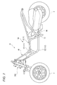
- FIG. 7 shows a body frame 10 of the lean vehicle 1 according to the present embodiment.
- the vehicle body frame 10 includes a vehicle-side monolithic body 100 and a link-side monolithic body 200.
- FIG. 8 is a perspective view showing the vehicle-side monolithic body 100.
- FIG. 9 is a sectional view of the vehicle-side monolithic body 100.
- a black-out area indicates a welded portion.
- the vehicle-body-side monolithic body 100 includes a right frame 11 extending in the front-rear direction and a left frame 12 extending in the front-rear direction.
- the left frame 12 is provided on the left side of the right frame 11.
- the right frame 11 includes an upper right frame 111 and a lower right frame 112 provided below the upper right frame 111.
- the left frame 12 includes an upper left frame 121 and a lower left frame 122 provided below the upper left frame 121.
- the vehicle-side monolithic body 100 has a power unit support portion 13.
- the power unit support portion 13 supports the power unit 96 so as to be able to swing with respect to the vehicle body side monolithic body 100.
- the power unit support 13 is welded to the lower right frame 112 and the lower left frame 122.
- the coupling portion 40 includes a right plate portion 41 (see FIG. 9), a left plate portion 42, an upper plate portion 43 (see FIG. 9), a lower plate portion 44, and a front plate portion 45.
- These right plate portion 41, left plate portion 42, upper plate portion 43, lower plate portion 44, and front plate portion 45 are plate-shaped parts.
- Right plate portion 41 is welded to upper right frame 111 and lower right frame 112.
- the left plate portion 42 is welded to the upper left frame 121 and the lower left frame 122.
- the upper plate part 43 is welded to the upper right frame 111 and the upper left frame 121.
- the lower plate portion 44 is welded to the lower right frame 112 and the lower left frame 122.
- the front plate 45 is welded to the front end of the upper right frame 111, the front end of the lower right frame 112, the front end of the upper left frame 121, and the front end of the lower left frame 122.
- the normal direction of the front plate portion 45 is parallel to the lower intermediate leaning axis LDI.
- three upper bolt through holes 46 through which three upper bolts 97 are respectively provided are provided in the upper portion of the front plate portion 45.
- three lower bolt through holes 47 through which three lower bolts 98 are respectively passed are provided in the lower portion of the front plate portion 45.
- An intermediate bolt through hole 48 (see FIG. 9) through which the intermediate bolt 99 is inserted is provided at the center of the front plate portion 45.
- the vehicle-body-side monolithic body 100 includes a bolt support 49 welded to the front plate 45 and the upper plate 43.
- the bolt support 49 extends in the front-rear direction.
- the front portion of the bolt support portion 49 is welded to the front plate portion 45, and the rear portion of the bolt support portion 49 is welded to the upper plate portion 43.
- the bolt supporting portion 49 is provided with an intermediate bolt through hole 48 into which the intermediate bolt 99 is inserted. That is, the bolt support portion 49 is welded to the vehicle body-side monolithic body 100 at two locations along the axial direction of the intermediate bolt 99.
- FIG. 10 is a perspective view showing the link-side monolithic body 200.
- FIG. 11 is a sectional view of the link-side monolithic body 200.
- the main pipe portion 21 supports the steering shaft 62 so as to be rotatable around the intermediate steering axis SI.
- the upper boss portion 22 supports an intermediate portion of the upper cross member 51 so as to be rotatable around an upper intermediate leaning axis LUI.
- the lower boss portion 23 supports an intermediate portion of the lower cross member 52 so as to be rotatable around a lower intermediate leaning axis LDI.
- the upper boss portion 22 and the lower boss portion 23 are welded to the main pipe portion 21.
- the upper bolt mounting portion 24 and the lower bolt mounting portion 25 are monolithically connected to form an integral body.
- the upper bolt mounting part 24 is a metal plate bent in a U-shape.
- the upper bolt mounting part 24 is welded to the rear part of the main pipe part 21.
- the upper bolt mounting portion 24 is provided with three bolt mounting holes 39 through which the upper bolts 97 are respectively passed.
- the upper bolt mounting portion 24 is provided at a height substantially equal to that of the upper boss portion 22 in the direction of the intermediate steering axis SI.
- the lower bolt mounting portion 25 includes a pipe portion 36 and a plate-shaped portion 37 provided at a rear end of the pipe portion.
- the front end of the pipe 36 is welded to the rear of the main pipe 21.
- the plate-like portion 37 is provided with three bolt mounting holes 38 through which the lower bolts 98 pass.
- the lower bolt mounting portion 25 is provided at a height similar to that of the lower boss portion 23 in the direction of the intermediate steering axis SI.
- the lower boss 23 includes a lower front boss 231 that rotatably supports the lower front cross element 521 and a lower rear boss 232 that rotatably supports the lower rear cross element 522.
- the upper boss portion 22 is provided so as to protrude forward from a front portion of the main pipe portion 21.
- the upper boss 22 is provided with an upper hole 32 into which the upper shaft member 31 is inserted.
- the upper middle leaning axis LUI which is the rotation axis of the upper cross member 51, passes through the upper hole 32.
- the upper shaft member 31 protrudes forward from the upper hole 32 and is fixed to an inner ring of an upper intermediate leaning bearing portion 51 a provided on the upper cross member 51.
- the central axis of the upper shaft member 31 matches the upper middle leaning axis LUI.
- the lower boss 23 has a lower front boss 231 and a lower rear boss 232.
- the lower front boss portion 231 is provided so as to protrude forward from a front portion of the main pipe portion 21.
- the lower front boss 231 is provided with a lower front hole 35 into which the lower front shaft member 33 is inserted.
- the lower intermediate leaning axis LDI which is the rotation axis of the lower cross member 52, passes through the lower front hole 35.
- the lower front shaft member 33 protrudes forward from the lower front hole 35 and is fixed to an inner ring of a lower intermediate leaning bearing portion 52 a provided on the lower front cross element 521.
- the central axis of the lower front shaft member 33 coincides with the lower intermediate leaning axis LDI.
- the lower rear boss portion 232 is provided so as to protrude rearward from the rear portion of the main pipe portion 21.
- the lower rear boss portion 232 is provided with a lower rear hole portion 34 into which the intermediate bolt 99 is inserted.
- a lower intermediate leaning axis LDI which is a rotation axis of the lower cross member 52, passes through the lower rear hole portion.
- the intermediate bolt 99 projects rearward from the lower rear hole portion 34 and is fixed to the inner ring of the lower rear leaning bearing portion 52b provided in the lower rear cross element 522.
- the central axis of the intermediate bolt 99 coincides with the lower intermediate leaning axis LDI.
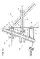
- FIG. 12 is a cross-sectional view showing a joint portion between the vehicle body side monolithic body 100 and the link side monolithic body 200. As shown in FIG. 12, the vehicle body side monolithic body 100 and the link side monolithic body 200 are connected by an upper bolt 97, a lower bolt 98, and an intermediate bolt 99.
- the upper bolt 97 penetrates the front plate portion 45 of the vehicle-side monolithic body 100 and the upper bolt mounting portion 24 of the link-side monolithic body 200.
- the lower bolt 98 passes through the front plate portion 45 of the vehicle-side monolithic body 100 and the lower bolt mounting portion 25 of the link-side monolithic body 200.
- the upper bolt 97 has a central upper intermediate bolt 97a located on the lower intermediate leaning axis LDI when viewed from above, and a rightward side from the lower intermediate leaning axis LDI when viewed from above. And an upper left bolt 97c provided to the left of the lower intermediate leaning axis LDI when viewed from above.
- the lower bolt 98 includes a central lower intermediate bolt 98a located on the lower intermediate leaning axis LDI when viewed from above, and a lower right bolt 98b provided to the right of the lower intermediate leaning axis LDI when viewed from above. And a lower left bolt 98c provided to the left of the lower intermediate leaning axis LDI when viewed from above.
- the intermediate bolt 99 includes a lower rear hole portion 34 provided in the lower rear boss portion 232 of the link side monolithic body 200, an inner ring of the lower rear leaning bearing portion 52 b of the lower rear cross element 522, and a bolt of the vehicle body side monolithic body 100.
- the support portion 49 penetrates.
- the intermediate bolt 99 is a stud bolt.
- the front part of the intermediate bolt 99 is screwed into the lower rear hole part 34.
- the rear portion of the intermediate bolt 99 projects rearward from the bolt support portion 49.
- a nut 101 is screwed to the rear end of the intermediate bolt 99 projecting rearward from the bolt support 49.
- the intermediate bolt 99 is provided on the lower intermediate leaning axis LDI when viewed from above.
- the link side monolithic body 200 that rotatably supports the link mechanism 5 and the steering shaft 62 is fastened to the vehicle body side monolithic body 100 with the bolts 97 to 99, so that welding is performed. At this time, deformation of the upper boss portion 22 and the lower boss portion 23 is avoided.
- a member and B member are connected monolithically to form a monolithic body (A member and B member are connected monolithically so so as to make one body)” is a metallic A member.
- a mode in which the member and the metal B member are connected so as to be continuous by metal is referred to as being monolithically joined and integrated.
- a member in which the A member and the B member are formed by casting and are connected to each other is also referred to as being monolithically joined to be an integral body.
- a member in which the A member and the B member are connected by a fastening means such as a bolt has a gap between the A member and the B member. I do not call it.
- a structure in which the A member and the B member are monolithically integrated tends to have higher strength than a structure in which the A member and the B member are connected by fastening means.
- the structure on the vehicle body side is integrated as a vehicle-side monolithic body 100 to increase the strength
- the structure supporting the link mechanism 5 and the steering shaft 62 is integrated as a link-side monolithic body 200 to increase the strength. Is increasing. By means of connecting these groups of structures having increased strength with bolts, the strength of the entire vehicle is increased while ensuring ease of assembly.
- the body-side monolithic body 100 can be designed in any shape as long as the right frame 11 and the left frame 12 of the body frame 10 are configured to be monolithically combined to form an integral body. Therefore, for example, the present invention is advantageous when a new vehicle is provided by using the newly designed link mechanism 5 and the body frame 10 of the existing lean vehicle 1. Unlike the present invention, when the body frame 10 is welded to the main pipe portion 21, it is necessary to change the design of the body frame 10 of the existing lean vehicle 1 so as to match the newly designed link mechanism 5. However, according to the present invention, if the vehicle-body-side monolithic body 100 is formed on the body frame 10 of the existing lean vehicle 1 and the link-side monolithic body 200 suitable for the new link mechanism 5 is designed, it is relatively simple. Vehicle can be provided.
- the lower cross member 52 has a lower rear cross element 522 located behind the link-side monolithic body 200,
- the lower boss portion 23 has a lower rear hole portion 34 in which a lower rear shaft member that supports the lower rear cross element 522 so as to be rotatable around a lower intermediate leaning axis LDI is supported.
- the intermediate bolt 99 is supported by the lower rear hole 34.
- the intermediate bolt 99 can be provided at a position where the intermediate bolt 99 does not interfere with the lower cross member 52 and does not increase the body frame 10 in the vertical direction.
- the intermediate bolt 99 extends from the lower rear hole portion 34, passes through the lower rear cross element 522, and is fastened to the vehicle body side monolithic body 100.
- the intermediate bolt 99 can be provided at a position where the intermediate bolt 99 does not interfere with the lower cross member 52 and does not increase the body frame 10 in the vertical direction.
- the intermediate bolt 99 extends along the lower intermediate leaning axis LDI.
- the intermediate bolt 99 can be provided at a position where the intermediate bolt 99 does not interfere with the lower cross member 52 and does not increase the body frame 10 in the vertical direction.
- a bolt support portion 49 (an example of a first fastening portion) into which the intermediate bolt 99 is inserted is monolithically coupled to the vehicle body-side monolithic body 100 to form an integral body.
- the bolt support portions 49 are fixed to the body frame 10 at a plurality of positions in the axial direction of the intermediate bolt 99.
- a front plate portion 45 (an example of a plate-shaped portion) whose normal direction is parallel to the lower intermediate leaning axis LDI is monolithically coupled to the vehicle body-side monolithic body 100 to be integrated.
- the front plate portion 45 since the front plate portion 45 is in surface contact with the link-side monolithic body 200, the front plate portion 45 can easily receive a large force. Further, since the planar front plate portion 45 comes into contact with the link-side monolithic body 200, it can be connected to the link-side monolithic body 200 with high dimensional accuracy.
- the lean vehicle 1 includes: An upper bolt 97 provided above the lower cross member 52 and provided on the right and left sides of the lower middle leaning axis LDI, and a right side of the lower cross member 52 provided below the lower cross member LDI. And at least one of a lower bolt 98 provided on the left side.
- the link side monolithic body 200 and the vehicle body side monolithic body 100 are connected by at least one of the upper bolt 97 and the lower bolt 98 (both in the above embodiment) and the intermediate bolt 99.
- the intermediate bolt 99 Have been. Therefore, for example, when both the right front wheel 2 and the left front wheel 3 ride on a step, when a force is applied to the link-side monolithic body 200 such that the lower part is pushed backward and the upper part is pushed forward, The force can be received by at least one of the bolt 97 and the lower bolt 98 and the intermediate bolt 99.
- An upper cross member 51 is provided in front of the link-side monolithic body 200,
- An upper bolt 97 is provided behind the link-side monolithic body 200 at a position overlapping the upper cross member 51 in a front view of the lean vehicle 1.
- the upper front cross element can effectively receive the force pushing the link-side monolithic body 200 backward by the upper bolt 97. Further, since the upper bolt 97 can be disposed using the space on the opposite side of the upper front cross element with the main pipe portion 21 of the link-side monolithic body 200 interposed therebetween, the vehicle is prevented from being enlarged.
- the right frame 11 An upper right frame 111 extending in the front-rear direction, It has a lower right frame 112 extending in the front-rear direction and located below the upper right frame 111,
- the left frame 12 An upper left frame 121 extending in the front-rear direction, It has a lower left frame 122 extending in the front-rear direction and located below the upper left frame 121,
- the upper right frame 111, the lower right frame 112, the upper left frame 121, and the lower left frame 122 are monolithically connected to form an integral body.
- the upper right frame 111, the lower right frame 112, the upper left frame 121, and the lower left frame 122 are monolithically combined to form a single body-side monolithic body 100. For this reason, the strength of the vehicle-side monolithic body 100 is further increased, and the force input from the link-side monolithic body 200 can be more easily received.
- the upper cross member 51 is located forward of the main pipe portion 21,
- the lower cross member 52 has a lower front cross element 521 located forward of the main pipe portion 21 and a lower rear cross element 522 located rearward of the link support section.
- An upper boss portion 22 that supports an upper shaft member 31 that rotatably supports the upper cross member 51 around an upper intermediate leaning axis LUI;
- a lower front boss 231 supporting a lower front shaft member 33 that rotatably supports the lower front cross element 521 around a lower intermediate leaning axis LDI;
- a lower rear boss portion 232 supporting a lower rear shaft member rotatably supporting the lower rear cross element 522 about a lower intermediate leaning axis LDI is monolithically coupled to the link side monolithic body 200 to be an integral body. .
- the lower cross member 52 includes the lower front cross element 521 and the lower rear cross element 522, so that the rigidity of the lower cross member 52 is increased.
- the upper cross member 51 is provided forward of the main pipe portion 21, and the lower cross member 52 is provided with a lower front cross element 521 provided forward of the main pipe portion 21 and the main pipe portion 21.
- the configuration has been described in which the lower rear cross element 522 provided further rearward, and the intermediate bolt 99 penetrates the lower rear cross element 522 to fasten the link side monolithic body and the vehicle body side monolithic body.
- the present invention is not limited to this structure.
- the upper cross member has an upper front cross element provided in front of the main pipe portion 21 and an upper rear cross element provided in back of the main pipe portion 21, and the lower cross member 52 is It may be provided in front.
- the intermediate bolt penetrates the upper rear cross element to fasten the link side monolithic body and the vehicle body side monolithic body.
- the upper cross member includes an upper front cross element provided forward of the main pipe portion 21 and an upper rear cross element provided rearward of the main pipe portion 21, and the lower cross member 52 includes A lower front cross element 521 provided forward of the section 21 and a lower rear cross element 522 provided rearward of the main pipe section 21 may be provided.
- a structure in which the link side monolithic body and the vehicle body side monolithic body are fastened by at least one of the upper intermediate bolt penetrating the upper rear cross element and the lower intermediate bolt penetrating the lower rear cross element 522 may be employed. it can.
- the lean vehicle 1 includes two front wheels 2 and 3 and one rear wheel 4. However, a plurality of rear wheels may be provided.
- the rear wheel 4 is arranged behind the left front wheel 3 and the right front wheel 2 in the front-rear direction of the body frame 10.
- at least one wheel may be provided rearward of the left front wheel 3 and the right front wheel 2 in the front-rear direction of the body frame 10.
- the driving force from the power source of the power unit 96 can be supplied to the left front wheel 3, the right front wheel 2, and at least one of the wheels.
- the handlebar 61 is formed of a single member extending in the left-right direction of the body frame.
- the handlebar 61 is provided with a left handle portion operated by the driver's left hand and a right handle operated by the driver's right hand.
- a configuration in which the units are provided separately can be adopted.
- a configuration including a cross member other than the upper cross member 51 and the lower cross member 52 can be adopted.
- the “upper cross member” and the “lower cross member” are simply named based on the relative vertical relationship.
- the upper cross member does not mean the uppermost cross member in the link mechanism 5.
- the upper cross member means a cross member located above another cross member.
- the lower cross member does not mean the lowest cross member in the link mechanism 5.
- the lower cross member means a cross member located below another cross member.
- each of the upper front cross member, the lower front cross member, and the lower rear cross member has a right end supporting the upper part of the right side part, a left end supporting the upper part of the left side part, and a link side.
- An example is shown in which a single-piece member integrally provided with an intermediate portion supported by a monolithic body is shown. The present invention is not limited to this.
- At least one of the upper front cross member, the lower front cross member, and the lower rear cross member is supported by the right end supporting the upper part of the right side part, the left end supporting the upper part of the left side part, and the link side monolithic body.
- the expression “displaceably arranged with respect to the body frame 10” refers to not only a part or a member directly fixed to the body frame 10 but also the body frame 10. Includes those that are fixed to fixed vehicle parts (fuel tanks, brackets, power units, etc.).
- fixing includes fixing via a vibration isolating member or the like.
- a front two-wheel lean vehicle that can be assembled without welding a link support portion to a vehicle body frame.
Landscapes
- Engineering & Computer Science (AREA)
- Mechanical Engineering (AREA)
- Automatic Cycles, And Cycles In General (AREA)
- Vehicle Body Suspensions (AREA)
Abstract
リーン車両(1)は、右フレーム(11)と左フレーム(12)とがモノリシックに結合されて一体物とされ、パワーユニット支持部(13)が設けられる車体側モノリシック体(100)と、リンク側モノリシック体(200)とを有する。リンク側モノリシック体(200)において、リンク機構(5)の上クロス部材(51)を支持する上ボス部(22)と、下クロス部材(52)を支持する下ボス部(23)と、ステアリングシャフト(62)を回動可能に支持するメインパイプ部(21)とがモノリシックに結合されて一体物とされている。リンク側モノリシック体(200)は車体側モノリシック体(100)にボルト(97,98,99)で締結されている。
Description
本発明は、傾斜可能な車体フレームと、その車体フレームの左右方向に並ぶように配置された左前輪と右前輪を備えているリーン車両に関する。
特許文献1および特許文献2は、右前輪と左前輪と1つの後輪とを有し、右方に傾斜して右旋回し左方に傾斜して左旋回するリーン車両を開示している。このリーン車両は、車体フレームの傾斜に応じて車体フレームの上下方向における右前輪および左前輪の相対位置を変化させるパラレロリンク機構を有している。このパラレロリンク機構は、略前後方向に延びるリンク軸線回りに揺動可能にリンク支持部に支持されている。
パラレロリンク機構は、中間部でリンク軸線回りに揺動可能にリンク支持部に支持された上クロス部材と、中間部でリンク軸線回りに揺動可能にリンク支持部に支持された下クロス部材と、上クロス部材の右部および下クロス部材の右部に揺動可能に連結されて右緩衝装置の上部を支持する右サイド部材と、上クロス部材の左部および下クロス部材の左部に揺動可能に連結されて左緩衝装置の上部を支持する左サイド部材を有している。リンク支持部は車体フレームに支持されている。
ところで特許文献1に記載のリーン車両においては、右前輪が通過する路面と左前輪が通過する路面が異なるため、右前輪と左前輪に異なる大きさの前後方向の力が作用する。このため、パラレロリンク機構を支持するリンク支持部には、上下方向に延びる軸線回りにねじろうとする力が作用する。
例えば右前輪が段差に乗り上げ左前輪が平坦な路面を通過するとき、右前輪を後方に押す大きな力が作用し左前輪には前後方向の力が作用しない。このため、リーン車両の上方から見て、リンク支持部には時計回りにねじろうとする力が作用する。
このようにリンク支持部をねじろうとする力を支えるために、特許文献1に記載のリーン車両においては、パワーユニットを支持する剛性の高い右フレームおよび左フレームにリンク支持部を溶接している。リンク支持部の右部に右フレームが溶接され、リンク支持部の左部に左フレームが溶接されている。特許文献2に記載のリーン車両においては、右フレームおよび左フレームを単一の太いフレームに溶接し、この太いフレームにリンク支持部を溶接している。このような構造により、リンク支持部に作用する大きなねじり力に対する接続強度が確保されている。
しかし特許文献1のリーン車両においては右フレームおよび左フレームをリンク支持部まで延びる形状とし、さらに右フレームの前端を左方に屈曲させてリンク支持部の右部まで到達させ、左フレームの前端を右方に屈曲させてリンク支持部の左部まで到達させている。このように特許文献1の構造においては、右フレームの形状と左フレームの形状に大きな制約がある。また、特許文献2のリーン車両においては、単一の太いフレームを設ける空間を確保するために、リーン車両が大型化しやすい。
ところで、リンク支持部は、上ボス部と下ボス部を有している。上ボス部の先端には上クロス部材を支持する上軸部材が設けられている。上軸部材は、上クロス部材を上中間軸線回りに揺動可能に支持している。下ボス部の先端面には下クロス部材を支持する下軸部材が設けられている。下軸部材は、下クロス部材を下中間軸線回りに揺動可能に支持している。上軸部材の中心軸線が上クロス部材の上中間リーニング軸線となるため、上ボス部には厳しい形状精度が要求されている。下軸部材の中心軸線が下クロス部材の下中間リーニング軸線となるため、下ボス部には厳しい形状精度が要求されている。
例えば特許文献1のリーン車両においては、リンク支持部に上ボス部を溶接した後に、上ボス部に上軸部材を支持する孔を形成し、上ボス部の近傍のリンク支持部と車体フレームとを溶接することが考えられる。しかしながら上ボス部に精度よく孔を形成できたとしても、その後に行うリンク支持部と車体フレームとの溶接作業時に生じる熱によって上ボス部が伸縮して変形してしまう。その結果、上ボス部に設けた孔の精度が加工時から劣化してしまう。
このため、上ボス部および下ボス部の近傍に溶接部位を設けると、溶接時の熱により変形して上軸部材の中心軸線や下軸部材の中心軸線が所定の方向からずれてしまう恐れがある。このため、上ボス部および下ボス部の近傍に溶接部位を設けたくない。
このため、上ボス部および下ボス部の近傍に溶接部位を設けると、溶接時の熱により変形して上軸部材の中心軸線や下軸部材の中心軸線が所定の方向からずれてしまう恐れがある。このため、上ボス部および下ボス部の近傍に溶接部位を設けたくない。
このような観点から、特許文献1のリーン車両においては、上ボス部および下ボス部の前後方向長さを大きくして上ボス部および下ボス部の熱容量を大きく確保し、溶接時に上ボス部および下ボス部を高温になりにくくしている。また、特許文献2のリーン車両においては、上ボス部および下ボス部から離れた個所でリンク支持部と車体フレームとを溶接している。
このように、上ボス部の精度および下ボス部の精度を確保しつつリンク支持部を車体フレームに溶接するために、車体フレームやリンク支持部の設計に大きな制約が生じている。そこで本発明者は、リンク支持部を溶接することなく車体フレームに取り付けることができれば、設計の自由度が高められるのではないかと期待した。
そこで本発明は、リンク支持部を車体フレームに溶接することなく組み立てることができる前二輪リーン車両を提供することを目的とする。
上記の目的を達成するために、本発明がとりうる一態様は、リーン車両であって、
右旋回時にリーン車両の右方に傾斜し、左旋回時に前記リーン車両の左方へ傾斜可能な車体フレームと、
右車軸線方向に延びる右車軸部材回りに回転する右前輪と、
前記右前輪より前記車体フレームの左方に設けられ、左車軸線方向に延びる左車軸部材回りに回転する左前輪と、
前記車体フレームの傾斜に応じて前記車体フレームの上下方向における前記右前輪および前記左前輪の相対位置を変化させるリンク機構と、
前記右前輪を下部で支持し、前記リンク機構に対する前記右前輪の相対変位を緩衝する右緩衝装置と、
前記左前輪を下部で支持し、前記リンク機構に対する前記左前輪の相対変位を緩衝する左緩衝装置と、
パワーユニットを前記車体フレームに支持するパワーユニット支持部と、
ステアリング機構と、を有し、
前記車体フレームは、
前後方向に延びる右フレームと前記右フレームよりも左方に設けられて前後方向に延びる左フレームとがモノリシックに結合されて一体物とされ、前記パワーユニット支持部が設けられる車体側モノリシック体と、
リンク側モノリシック体とを有し、
前記リンク機構は、
前記右緩衝装置の上部を前記車体フレームの上下方向に延びる右操舵軸線回りに回動可能に支持する右サイド部材と、
前記左緩衝装置の上部を前記右操舵軸線と平行な左操舵軸線回りに回動可能に支持する左サイド部材と、
前記右サイド部材の上部を右端部に前記車体フレームの前後方向に延びる上右リーニング軸線回りに回動可能に支持し、前記左サイド部材の上部を左端部に前記上右リーニング軸線に平行な上左リーニング軸線回りに回動可能に支持し、中間部が前記リンク側モノリシック体に前記上右リーニング軸線に平行な上中間リーニング軸線回りに回動可能に支持される上クロス部材と、
前記右サイド部材の下部を右端部に前記上右リーニング軸線に平行な下右リーニング軸線回りに回動可能に支持し、前記左サイド部材の下部を左端部に前記上左リーニング軸線に平行な下左リーニング軸線回りに回動可能に支持し、中間部が前記リンク側モノリシック体に前記上中間リーニング軸線と平行な下中間リーニング軸線回りに回動可能に支持される下クロス部材と、を有し、
前記ステアリング機構は、
操舵力が入力される操舵力入力部と、
前記操舵力入力部に連結され、前記車体フレームの上下方向に延びる中間操舵軸線回りに回転可能なステアリングシャフトと、
前記ステアリングシャフトに連結され、前記ステアリングシャフトの回動を前記右緩衝装置および前記左緩衝装置に伝達する操舵力伝達機構と、を有し、
前記リンク側モノリシック体において、
前記ステアリングシャフトを前記中間操舵軸線回りに回動可能に支持するメインパイプ部と、
前記上クロス部材の前記中間部を前記上中間リーニング軸線回りに回動可能に支持する上ボス部と、
前記下クロス部材の前記中間部を前記下中間リーニング軸線回りに回動可能に支持する下ボス部と、がモノリシックに結合されて一体物とされており、
前記リンク側モノリシック体は、前記車体側モノリシック体にボルトで締結されている。
右旋回時にリーン車両の右方に傾斜し、左旋回時に前記リーン車両の左方へ傾斜可能な車体フレームと、
右車軸線方向に延びる右車軸部材回りに回転する右前輪と、
前記右前輪より前記車体フレームの左方に設けられ、左車軸線方向に延びる左車軸部材回りに回転する左前輪と、
前記車体フレームの傾斜に応じて前記車体フレームの上下方向における前記右前輪および前記左前輪の相対位置を変化させるリンク機構と、
前記右前輪を下部で支持し、前記リンク機構に対する前記右前輪の相対変位を緩衝する右緩衝装置と、
前記左前輪を下部で支持し、前記リンク機構に対する前記左前輪の相対変位を緩衝する左緩衝装置と、
パワーユニットを前記車体フレームに支持するパワーユニット支持部と、
ステアリング機構と、を有し、
前記車体フレームは、
前後方向に延びる右フレームと前記右フレームよりも左方に設けられて前後方向に延びる左フレームとがモノリシックに結合されて一体物とされ、前記パワーユニット支持部が設けられる車体側モノリシック体と、
リンク側モノリシック体とを有し、
前記リンク機構は、
前記右緩衝装置の上部を前記車体フレームの上下方向に延びる右操舵軸線回りに回動可能に支持する右サイド部材と、
前記左緩衝装置の上部を前記右操舵軸線と平行な左操舵軸線回りに回動可能に支持する左サイド部材と、
前記右サイド部材の上部を右端部に前記車体フレームの前後方向に延びる上右リーニング軸線回りに回動可能に支持し、前記左サイド部材の上部を左端部に前記上右リーニング軸線に平行な上左リーニング軸線回りに回動可能に支持し、中間部が前記リンク側モノリシック体に前記上右リーニング軸線に平行な上中間リーニング軸線回りに回動可能に支持される上クロス部材と、
前記右サイド部材の下部を右端部に前記上右リーニング軸線に平行な下右リーニング軸線回りに回動可能に支持し、前記左サイド部材の下部を左端部に前記上左リーニング軸線に平行な下左リーニング軸線回りに回動可能に支持し、中間部が前記リンク側モノリシック体に前記上中間リーニング軸線と平行な下中間リーニング軸線回りに回動可能に支持される下クロス部材と、を有し、
前記ステアリング機構は、
操舵力が入力される操舵力入力部と、
前記操舵力入力部に連結され、前記車体フレームの上下方向に延びる中間操舵軸線回りに回転可能なステアリングシャフトと、
前記ステアリングシャフトに連結され、前記ステアリングシャフトの回動を前記右緩衝装置および前記左緩衝装置に伝達する操舵力伝達機構と、を有し、
前記リンク側モノリシック体において、
前記ステアリングシャフトを前記中間操舵軸線回りに回動可能に支持するメインパイプ部と、
前記上クロス部材の前記中間部を前記上中間リーニング軸線回りに回動可能に支持する上ボス部と、
前記下クロス部材の前記中間部を前記下中間リーニング軸線回りに回動可能に支持する下ボス部と、がモノリシックに結合されて一体物とされており、
前記リンク側モノリシック体は、前記車体側モノリシック体にボルトで締結されている。
上記リーン車両において、
前記下クロス部材は、前記リンク側モノリシック体よりも後方に位置する下後クロス要素を有し、
前記下ボス部は、前記下後クロス要素を前記下中間リーニング軸線回りに回動可能に支持する下後軸部材が支持される下後孔部を有し、
前記ボルトは、前記下後孔部に支持されていてもよい。
前記下クロス部材は、前記リンク側モノリシック体よりも後方に位置する下後クロス要素を有し、
前記下ボス部は、前記下後クロス要素を前記下中間リーニング軸線回りに回動可能に支持する下後軸部材が支持される下後孔部を有し、
前記ボルトは、前記下後孔部に支持されていてもよい。
上記リーン車両において、
前記ボルトは、前記下後孔部から延びて前記下後クロス要素を貫通して、前記車体側モノリシック体に締結されていてもよい。
前記ボルトは、前記下後孔部から延びて前記下後クロス要素を貫通して、前記車体側モノリシック体に締結されていてもよい。
上記リーン車両において、
前記ボルトは、前記下中間リーニング軸線に沿って延びていてもよい。
前記ボルトは、前記下中間リーニング軸線に沿って延びていてもよい。
上記リーン車両において、
前記ボルトが挿入される第一締結部が前記車体側モノリシック体にモノリシックに結合されて一体物とされており、
前記第一締結部は、前記ボルトの軸線方向の複数個所で前記車体フレームに固定されていてもよい。
前記ボルトが挿入される第一締結部が前記車体側モノリシック体にモノリシックに結合されて一体物とされており、
前記第一締結部は、前記ボルトの軸線方向の複数個所で前記車体フレームに固定されていてもよい。
上記リーン車両において、
法線方向が前記下中間リーニング軸線と平行な板状部が前記車体側モノリシック体にモノリシックに結合されて一体物とされていてもよい。
法線方向が前記下中間リーニング軸線と平行な板状部が前記車体側モノリシック体にモノリシックに結合されて一体物とされていてもよい。
上記リーン車両において、
前記下クロス部材より上方に設けられ、前記下中間リーニング軸線より右方および左方に設けられている上ボルトと、前記下クロス部材より下方に設けられ、前記下中間リーニング軸線より右方および左方に設けられている下ボルト、の少なくとも一方を含んでもよい。
前記下クロス部材より上方に設けられ、前記下中間リーニング軸線より右方および左方に設けられている上ボルトと、前記下クロス部材より下方に設けられ、前記下中間リーニング軸線より右方および左方に設けられている下ボルト、の少なくとも一方を含んでもよい。
上記リーン車両において、
前記リンク側モノリシック体よりも前方に前記上クロス部材が設けられており、
前記リーン車両の正面視で、前記上クロス部材と重なる位置で、前記リンク側モノリシック体よりも後方に前記上ボルトが設けられていてもよい。
前記リンク側モノリシック体よりも前方に前記上クロス部材が設けられており、
前記リーン車両の正面視で、前記上クロス部材と重なる位置で、前記リンク側モノリシック体よりも後方に前記上ボルトが設けられていてもよい。
上記リーン車両において、
前記右フレームは、
前後方向に延びる右上フレームと、
前後方向に延びて、前記右上フレームよりも下方に位置する右下フレームを有し、
前記左フレームは、
前後方向に延びる左上フレームと、
前後方向に延びて、前記左上フレームよりも下方に位置する左下フレームを有し、
前記右上フレームと、前記右下フレームと、前記左上フレームと、前記左下フレームと、が前記車体側モノリシック体にモノリシックに結合されて一体物とされていてもよい。
前記右フレームは、
前後方向に延びる右上フレームと、
前後方向に延びて、前記右上フレームよりも下方に位置する右下フレームを有し、
前記左フレームは、
前後方向に延びる左上フレームと、
前後方向に延びて、前記左上フレームよりも下方に位置する左下フレームを有し、
前記右上フレームと、前記右下フレームと、前記左上フレームと、前記左下フレームと、が前記車体側モノリシック体にモノリシックに結合されて一体物とされていてもよい。
上記リーン車両において、
前記上クロス部材は、前記メインパイプ部よりも前方に位置し、
前記下クロス部材は、前記メインパイプ部よりも前方に位置する下前クロス要素と、前記メインパイプ部よりも後方に位置する下後クロス要素と、を有し、
前記上クロス部材を前記上中間リーニング軸線回りに回動可能に支持する上軸部材を支持する前記上ボス部と、
前記下前クロス要素を前記下中間リーニング軸線回りに回動可能に支持する下前軸部材を支持する下前ボス部と、
前記下後クロス要素を前記下中間リーニング軸線回りに回動可能に支持する下後軸部材を支持する下後ボス部と、が前記リンク側モノリシック体にモノリシックに接合されて一体物とされていてもよい。
前記上クロス部材は、前記メインパイプ部よりも前方に位置し、
前記下クロス部材は、前記メインパイプ部よりも前方に位置する下前クロス要素と、前記メインパイプ部よりも後方に位置する下後クロス要素と、を有し、
前記上クロス部材を前記上中間リーニング軸線回りに回動可能に支持する上軸部材を支持する前記上ボス部と、
前記下前クロス要素を前記下中間リーニング軸線回りに回動可能に支持する下前軸部材を支持する下前ボス部と、
前記下後クロス要素を前記下中間リーニング軸線回りに回動可能に支持する下後軸部材を支持する下後ボス部と、が前記リンク側モノリシック体にモノリシックに接合されて一体物とされていてもよい。
本発明によれば、リンク支持部を車体フレームに溶接することなく組み立てることができる前二輪リーン車両が提供される。
添付の図面を参照しつつ、実施形態の例について、以下詳細に説明する。
添付の図面において、矢印Fは、リーン車両の前方向を示している。矢印Bは、リーン車両の後方向を示している。矢印Uは、リーン車両の上方向を示している。矢印Dは、リーン車両の下方向を示している。矢印Rは、リーン車両の右方向を示している。矢印Lは、リーン車両の左方向を示している。
添付の図面において、矢印Fは、リーン車両の前方向を示している。矢印Bは、リーン車両の後方向を示している。矢印Uは、リーン車両の上方向を示している。矢印Dは、リーン車両の下方向を示している。矢印Rは、リーン車両の右方向を示している。矢印Lは、リーン車両の左方向を示している。
リーン車両は、車体フレームを鉛直方向に対して左右方向に傾斜させて旋回する。そこでリーン車両を基準とした方向に加え、車体フレームを基準とした方向が定められる。添付の図面において、矢印FFは、車体フレームの前方向を示している。矢印FBは、車体フレームの後方向を示している。矢印FUは、車体フレームの上方向を示している。矢印FDは、車体フレームの下方向を示している。矢印FRは、車体フレームの右方向を示している。矢印FLは、車体フレームの左方向を示している。
本明細書において、「車体フレームの前後方向」、「車体フレームの左右方向」、および「車体フレームの上下方向」とは、リーン車両を運転する運転者から見たとき、車体フレームを基準とした前後方向、左右方向、および上下方向を意味する。「車体フレームの側方」とは、車体フレームの左右方向における右方あるいは左方を意味している。
本明細書において、「車体フレームの前後方向に延びる」とは、車体フレームの前後方向に対して傾いて延びることを含み、車体フレームの左右方向および上下方向と比較して、車体フレームの前後方向に近い傾きで延びることを意味する。
本明細書において、「車体フレームの左右方向に延びる」とは、車体フレームの左右方向に対して傾いて延びることを含み、車体フレームの前後方向および上下方向と比較して、車体フレームの左右方向に近い傾きで延びることを意味する。
本明細書において、「車体フレームの上下方向に延びる」とは、車体フレームの上下方向に対して傾いて延びることを含み、車体フレームの前後方向および左右方向と比較して、車体フレームの上下方向に近い傾きで延びることを意味する。
本明細書において、「リーン車両の直立状態」あるいは「車体フレームの直立状態」とは、無転舵状態かつ車体フレームの上下方向が鉛直方向と一致している状態を意味する。この状態においては、リーン車両を基準にした方向と車体フレームを基準にした方向は一致する。車体フレームを鉛直方向に対して左右方向に傾斜させて旋回しているときは、リーン車両の左右方向と車体フレームの左右方向は一致しない。またリーン車両の上下方向と車体フレームの上下方向も一致しない。しかしながら、リーン車両の前後方向と車体フレームの前後方向は一致する。
本明細書において、「車体フレームの左右方向における部材Aの左方」とは、車体フレームの左右方向における左方へ部材Aを平行移動させたときに当該部材Aが通過する空間を指す。部材Aの右方についても同様に定義される。
本明細書において、「部材Aよりも車体フレームの左右方向における左方」とは、車体フレームの左右方向における左方へ部材Aを平行移動させたときに当該部材Aが通過する空間に加え、当該空間から車体フレームの左右方向に直交する向きに広がる空間を含む。部材Aよりも右方についても同様に定義される。
本明細書において、「車体フレームの上下方向における部材Aの上方」とは、車体フレームの上下方向における上方へ部材Aを平行移動させたときに当該部材Aが通過する空間を指す。部材Aの下方についても同様に定義される。
本明細書において、「部材Aよりも車体フレームの上下方向における上方」とは、車体フレームの上下方向における上方へ部材Aを平行移動させたときに当該部材Aが通過する空間に加え、当該空間から車体フレームの上下方向に直交する向きに広がる空間を含む。部材Aよりも下方についても同様に定義される。
本明細書において、「車体フレームの前後方向における部材Aの前方」とは、車体フレームの前後方向における前方へ部材Aを平行移動させたときに当該部材Aが通過する空間を指す。部材Aの後方についても同様に定義される。
本明細書において、「部材Aよりも車体フレームの前後方向における前方」とは、車体フレームの前後方向における前方へ部材Aを平行移動させたときに当該部材Aが通過する空間に加え、当該空間から車体フレームの前後方向に直交する向きに広がる空間を含む。部材Aよりも後方についても同様に定義される。
本明細書において、「回転」とは、部材が軸線を中心として360度以上の角度で変位することを指す。本明細書において、「回動」とは、部材が軸線を中心として360度未満の角度で変位することを指す。
本明細書において、「連結される」とは、ある部材と別の部材が直接的に連結される場合だけでなく、ある部材と別の部材が、さらに別の部材を介して間接的に連結される場合を含む意味である。
図1から図12を参照しつつ、一実施形態に係るリーン車両1について説明する。図1に示されるように、リーン車両1は、右前輪2、左前輪3、後輪4、リンク機構5、およびステアリング機構6を備えている。
リーン車両1は、車体カバー90、シート95、パワーユニット96を含んでいる。
図1において、車体フレーム10は直立状態にある。図1を参照する以降の説明は、車体フレーム10の直立状態を前提にしている。図1は、リーン車両1の全体を車体フレーム10の左右方向における左方から見た左側面図である。
車体フレーム10は、ステアリングシャフト62を回動可能に支持するメインパイプ部21を含んでいる。
メインパイプ部21は、リーン車両1の前部に配置されている。車体フレーム10の左右方向からリーン車両1を見たとき、メインパイプ部21の上部は、メインパイプ部21の下部よりも車体フレーム10の前後方向における後方に配置されている。車体フレーム10の詳細は後に説明する。
メインパイプ部21は、リーン車両1の前部に配置されている。車体フレーム10の左右方向からリーン車両1を見たとき、メインパイプ部21の上部は、メインパイプ部21の下部よりも車体フレーム10の前後方向における後方に配置されている。車体フレーム10の詳細は後に説明する。
車体カバー90は、リーン車両1を構成する部品群の少なくとも一部を覆う車体部品である。車体カバー90は、フロントカバー91、二つのフロントフェンダ92、リアフェンダ93、およびレッグシールド94を含んでいる。
フロントカバー91は、シート95よりも車体フレーム10の前後方向における前方に配置されている。フロントカバー91は、リンク機構5とステアリング機構6の少なくとも一部を覆っている。フロントカバー91は、車体フレーム10に対して変位不能に配置されている。
各フロントフェンダ92の少なくとも一部は、フロントカバー91の下方にそれぞれ配置されている。各フロントフェンダ92の少なくとも一部は、右前輪2および左前輪3よりも上方に配置されている。
右前輪2および左前輪3は、メインパイプ部21よりも車体フレーム10の上下方向における下方に配置されている。右前輪2および左前輪3の少なくとも一部は、車体フレーム10の上下方向におけるフロントカバー91の下方に配置されている。
後輪4の少なくとも一部は、シート95よりも車体フレーム10の上下方向における下方に配置されている。後輪4の少なくとも一部は、車体フレーム10の上下方向におけるリアフェンダ93の下方に配置されている。
レッグシールド94は、車体フレーム10の前後方向における右前輪2および左前輪3よりも後方かつシート95よりも前方に配置されている。レッグシールド94は、リーン車両1の前方から見てシート95に着座した運転者の脚部の少なくとも一部を覆う位置に配置されている。
図2は、リーン車両1の前部を車体フレーム10の前後方向における前方から見た正面図である。図2において、車体フレーム10は直立状態にある。図2を参照する以降の説明は、車体フレーム10の直立状態を前提にしている。図2においては、破線で示されるフロントカバー91、二つのフロントフェンダ92を透視した状態を示している。
左前輪3は、車体フレーム10の一部であるメインパイプ部21よりも車体フレーム10の左右方向における左方に配置されている。右前輪2は、メインパイプ部21よりも車体フレーム10の左右方向における右方に配置されている。左前輪3と右前輪2は、車体フレーム10の左右方向に並ぶように配置されている。
二つのフロントフェンダ92は、左フェンダと右フェンダを含んでいる。左フェンダは、左前輪3の上面の少なくとも一部を覆っている。右フェンダは、右前輪2の上面の少なくとも一部を覆っている。
ステアリング機構6は、ハンドルバー61とステアリングシャフト62を含んでいる。ステアリングシャフト62は、ハンドルバー61の左右方向中央部から下方に向かって延びている。ステアリングシャフト62は、図示しない中間ステアリング軸受部を介してメインパイプ部21に支持されている。これにより、ステアリングシャフト62は、メインパイプ部21に対して中間操舵軸線SIを中心として回動可能である。
本実施形態に係るリーン車両1においては、平行四節リンク(パラレログラムリンクとも呼ばれる)方式のリンク機構5を採用している。
リンク機構5は、左前輪3と右前輪2よりも車体フレーム10の上下方向における上方に配置されている。リンク機構5は、上クロス部材51、下クロス部材52、左サイド部材53、および右サイド部材54を含んでいる。リンク機構5は、ハンドルバー61の操作に伴うステアリングシャフト62の中間操舵軸線SIを中心とする回動に連動しない。すなわち、リンク機構5は、中間操舵軸線SIを中心として、車体フレーム10に対して回動しない。
メインパイプ部21は、上中間リーニング軸受部51aを有している。上クロス部材51の中間部は、上中間リーニング軸受部51aを介してメインパイプ部21に支持されている。上クロス部材51は、上中間リーニング軸受部51aを通り車体フレーム10の前後方向に延びる上中間リーニング軸線LUIを中心として、メインパイプ部21に対して回動可能である。
メインパイプ部21は、下中間リーニング軸受部51bを有している。下クロス部材52の中間部は、下中間リーニング軸受部51bを介してメインパイプ部21に支持されている。下クロス部材52は、下中間リーニング軸受部51bを通り車体フレーム10の前後方向に延びる下中間リーニング軸線LDIを中心として、メインパイプ部21に対して回動可能である。
左サイド部材53は、上左リーニング軸受部53aを有している。上クロス部材51の左端部は、上左リーニング軸受部53aを介して左サイド部材53に連結されている。上クロス部材51は、上左リーニング軸受部53aを通り車体フレーム10の前後方向に延びる上左リーニング軸線LULを中心として、左サイド部材53に対して回動可能である。
右サイド部材54は、上右リーニング軸受部54aを有している。上クロス部材51の右端部は、上右リーニング軸受部54aを介して右サイド部材54に連結されている。上クロス部材51は、上右リーニング軸受部54aを通り車体フレーム10の前後方向に延びる上右リーニング軸線LURを中心として、右サイド部材54に対して回動可能である。
左サイド部材53は、下左リーニング軸受部53bを有している。下クロス部材52の左端部は、下左リーニング軸受部53bを介して左サイド部材53に連結されている。下クロス部材52は、下左リーニング軸受部53bを通り車体フレーム10の前後方向に延びる下左リーニング軸線LDLを中心として、左サイド部材53に対して回動可能である。
右サイド部材54は、下右リーニング軸受部54bを有している。下クロス部材52の右端部は、下右リーニング軸受部54bを介して右サイド部材54に連結されている。下クロス部材52は、下右リーニング軸受部54bを通り車体フレーム10の前後方向に延びる下右リーニング軸線LDRを中心として、右サイド部材54に対して回動可能である。
図3は、リーン車両1の前部を車体フレーム10の上下方向における上方から見た平面図である。図3において、車体フレーム10は直立状態にある。図3を参照する以降の説明は、車体フレーム10の直立状態を前提にしている。図3においては、破線で示されるフロントカバー91と二つのフロントフェンダ92を透視した状態を示している。
上クロス部材51は、メインパイプ部21よりも車体フレーム10の前後方向における前方に配置されている。上クロス部材51は、車体フレーム10の前後方向には湾曲することなく、車体フレーム10の左右方向に延びている板状部材である。
図2と図3に示されるように、下クロス部材52は、上クロス部材51よりも車体フレーム10の上下方向における下方に配置されている。下クロス部材52は、下前クロス要素521と下後クロス要素522を含んでいる。下前クロス要素521は、メインパイプ部21、左サイド部材53、および右サイド部材54よりも車体フレーム10の前後方向における前方に配置されている。下後クロス要素522は、メインパイプ部21、左サイド部材53、および右サイド部材54よりも車体フレーム10の前後方向における後方に配置されている。下前クロス要素521と下後クロス要素522は、車体フレーム10の左右方向に延びている。
図2と図3に示されるように、左サイド部材53は、車体フレーム10の左右方向におけるメインパイプ部21の左方に配置されている。左サイド部材53は、左前輪3よりも車体フレーム10の上下方向における上方に配置されている。左サイド部材53は、メインパイプ部21が延びる方向に延びている。左サイド部材53の上部は、その下部よりも車体フレーム10の前後方向における後方に配置されている。
図2と図3に示されるように、右サイド部材54は、車体フレーム10の左右方向におけるメインパイプ部21の右方に配置されている。右サイド部材54は、右前輪2よりも車体フレーム10の上下方向における上方に配置されている。右サイド部材54は、メインパイプ部21が延びる方向に延びている。右サイド部材54の上部は、その下部よりも車体フレーム10の前後方向における後方に配置されている。
上クロス部材51、下クロス部材52、左サイド部材53、および右サイド部材54は、上クロス部材51と下クロス部材52が相互に平行な姿勢を保ち、左サイド部材53と右サイド部材54が相互に平行な姿勢を保つように、メインパイプ部21に支持されている。
図2に示されるように、リーン車両1は、左懸架部7を備えている。左懸架部7は、左ブラケット71と左緩衝装置72を含んでいる。
左ブラケット71は、その上部に左回動部材(不図示)を備えている。左回動部材は、左サイド部材53の内部に配置され、左サイド部材53が延びる方向と同じ向きに延びている。左サイド部材53は、左ステアリング軸受部(不図示)を有している。左回動部材は、左ステアリング軸受部を介して左サイド部材53に支持されている。これにより、左回動部材は、左サイド部材53に対して、左操舵軸線SLを中心として回動可能である。すなわち、左ブラケット71は、左サイド部材53に対して、左操舵軸線SLを中心として回動可能に連結されている。
左操舵軸線SLは、左サイド部材53が延びる方向に延びている。図2に示されるように、左操舵軸線SLは、ステアリングシャフト62の中間操舵軸線SIと平行に、車体フレーム10の上下方向に延びている。図3に示されるように、左操舵軸線SLは、ステアリングシャフト62の中間操舵軸線SIと平行に、車体フレーム10の前後方向に延びている。
左緩衝装置72は、いわゆるテレスコピック式の緩衝機構である。図2に示されるように、左緩衝装置72は、左上テレスコピック要素721、左下テレスコピック要素722、および左車軸部材723を含んでいる。
左上テレスコピック要素721は、左ブラケット71に支持されている。左下テレスコピック要素722は、左上テレスコピック要素721に対して摺動可能に連結されている。左上テレスコピック要素721に対する左下テレスコピック要素722の摺動により、リンク機構5に対する左前輪3の車体フレーム10の上下方向への変位が緩衝される。
左車軸部材723は、左下テレスコピック要素722に支持されている。左車軸部材723は、左前輪3を支持している。左前輪3は、左車軸部材723を中心として回転可能である。
図2に示されるように、リーン車両1は、右懸架部8を備えている。右懸架部8は、右ブラケット81と右緩衝装置82を含んでいる。
右ブラケット81は、その上部に右回動部材(不図示)を備えている。右回動部材は、右サイド部材54の内部に配置され、右サイド部材54が延びる方向と同じ向きに延びている。右サイド部材54は、右ステアリング軸受部(不図示)を有している。右回動部材は、右ステアリング軸受部を介して右サイド部材54に支持されている。これにより、右回動部材は、右サイド部材54に対して、右操舵軸線SRを中心として回動可能である。すなわち、右ブラケット81は、右サイド部材54に対して、右操舵軸線SRを中心として回動可能に連結されている。
右操舵軸線SRは、右サイド部材54が延びる方向に延びている。図2に示されるように、右操舵軸線SRは、ステアリングシャフト62の中間操舵軸線SIと平行に、車体フレーム10の上下方向に延びている。図3に示されるように、右操舵軸線SRは、ステアリングシャフト62の中間操舵軸線SIと平行に、車体フレーム10の前後方向に延びている。
右緩衝装置82は、いわゆるテレスコピック式の緩衝機構である。図2に示されるように、右緩衝装置82は、右上テレスコピック要素821、右下テレスコピック要素822、および右車軸部材823を含んでいる。
右上テレスコピック要素821は、右ブラケット81に支持されている。右下テレスコピック要素822は、右上テレスコピック要素821に対して摺動可能に連結されている。右上テレスコピック要素821に対する右下テレスコピック要素822の摺動により、リンク機構5に対する右前輪2の車体フレーム10の上下方向への変位が緩衝される。
右車軸部材823は、右下テレスコピック要素822に支持されている。右車軸部材823は、右前輪2を支持している。右前輪2は、右車軸部材823を中心として回転可能である。
図3に示されるように、ステアリング機構6は、操舵力伝達機構63を含んでいる。操舵力伝達機構63は、中間伝達プレート631、左伝達プレート632、右伝達プレート633、中間ジョイント634、左ジョイント635、右ジョイント636、およびタイロッド637を含んでいる。
中間伝達プレート631は、ステアリングシャフト62の下部に設けられている。中間伝達プレート631は、メインパイプ部21に対して、ステアリングシャフト62の中間操舵軸線SIと平行に延びる軸線を中心として回動可能である。
左伝達プレート632は、中間伝達プレート631の左方に配置されている。左伝達プレート632は、左ブラケット71の下部に接続されている。左伝達プレート632は、左ブラケット71に対して相対回動不能である。左伝達プレート632は、左サイド部材53に対して、左操舵軸線SLを中心として回動可能である。
右伝達プレート633は、車体フレーム10の左右方向における中間伝達プレート631の右方に配置されている。右伝達プレート633は、右ブラケット81の下部に接続されている。右伝達プレート633は、右ブラケット81に対して相対回動不能である。右伝達プレート633は、右サイド部材54に対して、右操舵軸線SRを中心として回動可能である。
中間ジョイント634は、中間ジョイントステアリング軸受部634aを有している。中間ジョイントステアリング軸受部634aは、車体フレーム10の上下方向に延びる中間ジョイントステアリング軸線を規定している。中間ジョイント634は、中間ジョイントステアリング軸受部634aを介して中間伝達プレート631の前部に連結されている。これにより、中間ジョイント634は、中間伝達プレート631に対して、中間ジョイントステアリング軸線を中心として回動可能である。
左ジョイント635は、中間ジョイント634よりも車体フレーム10の左右方向における左方に配置されている。左ジョイント635は、左ジョイントステアリング軸受部635aを有している。左ジョイントステアリング軸受部635aは、車体フレーム10の上下方向に延びる左ジョイントステアリング軸線を規定している。左ジョイント635は、左ジョイントステアリング軸受部635aを介して左伝達プレート632の前部に連結されている。これにより、左ジョイント635は、左伝達プレート632に対して、左ジョイントステアリング軸線を中心として回動可能である。
右ジョイント636は、中間ジョイント634よりも車体フレーム10の左右方向における右方に配置されている。右ジョイント636は、右ジョイントステアリング軸受部636aを有している。右ジョイントステアリング軸受部636aは、車体フレーム10の上下方向に延びる右ジョイントステアリング軸線を規定している。右ジョイント636は、右ジョイントステアリング軸受部636aを介して右伝達プレート633の前部に連結されている。これにより、右ジョイント636は、右伝達プレート633に対して、右ジョイントステアリング軸線を中心として回動可能である。
中間ジョイント634は、中間ジョイントリーニング軸受部634bを有している。中間ジョイントリーニング軸受部634bは、車体フレーム10の前後方向に延びる中間ジョイントリーニング軸線を規定している。タイロッド637の中間部は、中間ジョイントリーニング軸受部634bと連結されている。タイロッド637の中間部は、中間ジョイントリーニング軸受部634bに対して、中間ジョイントリーニング軸線を中心として回動可能である。
左ジョイント635は、左ジョイントリーニング軸受部635bを有している。左ジョイントリーニング軸受部635bは、車体フレーム10の前後方向に延びる左ジョイントリーニング軸線を規定している。タイロッド637の左部は、左ジョイントリーニング軸受部635bと連結されている。タイロッド637の左部は、左ジョイントリーニング軸受部635bに対して、左ジョイントリーニング軸線を中心として回動可能である。
右ジョイント636は、右ジョイントリーニング軸受部636bを有している。右ジョイントリーニング軸受部636bは、車体フレーム10の前後方向に延びる右ジョイントリーニング軸線を規定している。タイロッド637の右部は、右ジョイントリーニング軸受部636bと連結されている。タイロッド637の右部は、右ジョイントリーニング軸受部636bに対して、右ジョイントリーニング軸線を中心として回動可能である。
左伝達プレート632は、左ジョイント635、タイロッド637、および中間ジョイント634を介して、中間伝達プレート631と連結されている。右伝達プレート633は、右ジョイント636、タイロッド637、および中間ジョイント634を介して、中間伝達プレート631と連結されている。左伝達プレート632と右伝達プレート633は、左ジョイント635、タイロッド637、および右ジョイント636を介して、相互に連結されている。換言すると、タイロッド637は、中間伝達プレート631を左伝達プレート632と右伝達プレート633に連結している。
次に、図4を参照しつつ、リーン車両1のステアリング動作について説明する。図4は、左前輪3と右前輪2を左転舵させた状態におけるリーン車両1の前部を、車体フレーム10の上下方向における上方から見た平面図である。図4において、車体フレーム10は直立状態にある。図4を参照する以降の説明は、車体フレーム10の直立状態を前提にしている。図4においては、破線で示されるフロントカバー91と二つのフロントフェンダ92を透視した状態を示している。
運転者がハンドルバー61を操作すると、ステアリングシャフト62は、中間操舵軸線SIを中心としてメインパイプ部21に対して回動する。図4に示す左転舵の場合、ステアリングシャフト62は、矢印LTの方向に回動する。中間伝達プレート631は、メインパイプ部21に対して、中間操舵軸線SIを中心として矢印LTの方向へ回動する。
中間伝達プレート631の矢印LTの方向への回動に伴って、タイロッド637の中間ジョイント634は、中間伝達プレート631に対して、矢印RTの方向に回動する。これにより、タイロッド637は、その姿勢を維持したまま、車体フレーム10の左右方向における左方かつ車体フレーム10の前後方向における後方へ移動する。
上記のタイロッド637の移動に伴って、タイロッド637の左ジョイント635と右ジョイント636は、それぞれ左伝達プレート632と右伝達プレート633に対して矢印RTの方向に回動する。これにより、タイロッド637はその姿勢を維持したまま、左伝達プレート632と右伝達プレート633が、矢印LTの方向に回動する。
左伝達プレート632が矢印LTの方向に回動すると、左伝達プレート632に対して相対回動不能である左ブラケット71が、左サイド部材53に対して、左操舵軸線SLを中心として、矢印LTの方向に回動する。
右伝達プレート633が矢印LTの方向に回動すると、右伝達プレート633に対して相対回動不能である右ブラケット81が、右サイド部材54に対して、右操舵軸線SRを中心として、矢印LTの方向に回動する。
左ブラケット71が矢印LTの方向に回動すると、左ブラケット71に支持されている左緩衝装置72が、左サイド部材53に対して、左操舵軸線SLを中心として、矢印Tの方向に回動する。左緩衝装置72が矢印Tの方向に回動すると、左車軸部材723を介して左緩衝装置72に支持されている左前輪3が、左サイド部材53に対して、左操舵軸線SLを中心として、矢印LTの方向に回動する。このとき、左フェンダもまた左前輪3とともに矢印LTの方向に回動する。
右ブラケット81が矢印LTの方向に回動すると、右ブラケット81に支持されている右緩衝装置82が、右サイド部材54に対して、右操舵軸線SRを中心として、矢印LTの方向に回動する。右緩衝装置82が矢印LTの方向に回動すると、右車軸部材823を介して右緩衝装置82に支持されている右前輪2が、右サイド部材54に対して、右操舵軸線SRを中心として、矢印LTの方向に回動する。このとき、右フェンダもまた右前輪2とともに矢印LTの方向に回動する。
右転舵するように運転者がハンドルバー61を操作すると、上述した各要素は、左転舵時とは逆方向に回動する。各要素の動きは左右が逆になるのみであるため、詳細な説明は省略する。
すなわち、操舵力伝達機構63は、左懸架部7と右懸架部8を連結し、ハンドルバー61の回動に応じて左前輪3と右前輪2を当該回動の方向に回動させるように構成されている。
次に、図2と図5を参照しつつ、リーン車両1の傾斜動作について説明する。図5は、車体フレーム10がリーン車両1の左方に傾斜した状態におけるリーン車両1の前部を、車体フレーム10の前後方向における前方から見た正面図である。図5においては、破線で示されるフロントカバー91、二つのフロントフェンダ92を透視した状態を示している。
図2に示されるように、直立状態における車体フレーム10の前方からリーン車両1を見たとき、リンク機構5は長方形状をなしている。図5に示されるように、傾斜状態における車体フレーム10の前方からリーン車両1を見たとき、リンク機構5は平行四辺形状をなしている。リンク機構5の作動と車体フレーム10の左右方向への傾斜は連動する。「リンク機構5の作動」とは、上クロス部材51と下クロス部材52が、それぞれ上中間リーニング軸線LUIと下中間リーニング軸線LDIを中心としてメインパイプ部21に対して回動し、上クロス部材51、下クロス部材52、左サイド部材53、および右サイド部材54が、それぞれ上左リーニング軸線LUL、上右リーニング軸線LUR、下左リーニング軸線LDL、および下右リーニング軸線LDRを中心として相対回動することにより、リンク機構5の形状が変化することを意味する。
例えば、図5に示されるように、運転者がリーン車両1を左方に傾斜させると、メインパイプ部21が鉛直方向に対して左方に傾斜する。メインパイプ部21が傾斜すると、上クロス部材51は、上中間リーニング軸受部51aを通る上中間リーニング軸線LUIを中心として、メインパイプ部21に対して、リーン車両1の前方から見て反時計回りに回動する。同様に、下クロス部材52は、下中間リーニング軸受部51bを通る下中間リーニング軸線LDIを中心として、メインパイプ部21に対して、リーン車両1の前方から見て反時計回りに回動する。これにより、上クロス部材51は、下クロス部材52に対して、車体フレーム10の左右方向における左方に移動する。
この移動により、上クロス部材51は、上左リーニング軸受部53aを通る上左リーニング軸線LULと上右リーニング軸受部54aを通る上右リーニング軸線LURを中心として、それぞれ左サイド部材53と右サイド部材54に対して、リーン車両1の前方から見て反時計回りに回動する。同様に、下クロス部材52は、下左リーニング軸受部53bを通る下左リーニング軸線LDLと下右リーニング軸受部54bを通る下右リーニング軸線LDRを中心として、それぞれ左サイド部材53と右サイド部材54に対して、リーン車両1の前方から見て反時計回りに回動する。これにより、左サイド部材53と右サイド部材54は、メインパイプ部21と平行な姿勢を保ったまま、鉛直方向に対してリーン車両1の左方に傾斜する。
このとき、下クロス部材52は、タイロッド637に対して、車体フレーム10の左右方向における左方に移動する。この移動により、タイロッド637は、中間ジョイント634、左ジョイント635、および右ジョイント636に対し、それぞれ中間ジョイントリーニング軸受部634b、左ジョイントリーニング軸受部635b、および右ジョイントリーニング軸受部636bを中心として回動する。これにより、タイロッド637は、上クロス部材51および下クロス部材52と平行な姿勢を保つ。
リーン車両1の左方への左サイド部材53の傾斜に伴い、左回動部材を介して左サイド部材53に支持されている左ブラケット71は、リーン車両1の左方に傾斜する。この傾斜に伴い、左ブラケット71に支持されている左緩衝装置72も、リーン車両1の左方に傾斜する。これにより、左緩衝装置72に支持されている左前輪3が、メインパイプ部21と平行な姿勢を保ったまま、リーン車両1の左方に傾斜する。
リーン車両1の左方への右サイド部材54の傾斜に伴い、右回動部材を介して右サイド部材54に支持されている右ブラケット81は、リーン車両1の左方に傾斜する。この傾斜に伴い、右ブラケット81に支持されている右緩衝装置82も、リーン車両1の左方に傾斜する。これにより、右緩衝装置82に支持されている右前輪2が、メインパイプ部21と平行な姿勢を保ったまま、リーン車両1の左方に傾斜する。
上記の左前輪3と右前輪2の傾斜動作に係る説明は、鉛直方向を基準としている。しかしながら、リーン車両1の傾斜動作時(リンク機構5の作動時)においては、車体フレーム10の上下方向と鉛直上下方向は一致しない。車体フレーム10の上下方向を基準とした場合、リンク機構5の作動時において、左前輪3と右前輪2は、車体フレーム10の上下方向における相対位置が変化している。換言すると、リンク機構5は、車体フレーム10の上下方向における左前輪3と右前輪2の相対位置を変更することにより、鉛直方向からリーン車両1の左方または右方に車体フレーム10を傾斜させる。これにより、リーン車両1は左方へ旋回する。
運転者がリーン車両1を右方に傾斜させると、各要素は右方に傾斜する。これにより、リーン車両1は右方へ旋回する。各要素の動きは左右が逆になるのみであるため、詳細な説明は省略する。
図6は、リーン車両1を左方へ傾斜させ、かつ左転舵させた状態におけるリーン車両1の前部を車体フレーム10の前後方向における前方から見た正面図である。図6においては、破線で示されるフロントカバー91と二つのフロントフェンダ92を透視した状態を示している。
操舵動作により、左前輪3は左操舵軸線SLを中心として反時計回りに回動され、右前輪2は右操舵軸線SRを中心として反時計回りに回動されている。傾斜動作により、左前輪3と右前輪2は、車体フレーム10とともにリーン車両1の左方に傾斜している。すなわち、この状態においては、リンク機構5は平行四辺形状を呈している。タイロッド637は、車体フレーム10の直立状態における位置から、車体フレーム10の左右方向における左方、かつ車体フレーム10の前後方向における後方に移動している。
上述したように、本実施形態に係るリーン車両1は、
右旋回時にリーン車両1の右方に傾斜し、左旋回時にリーン車両1の左方へ傾斜可能な車体フレーム10と、
右車軸線方向に延びる右車軸部材823回りに回転する右前輪2と、
右前輪2より車体フレーム10の左方に設けられ、左車軸線方向に延びる左車軸部材723回りに回転する左前輪3と、
車体フレーム10の傾斜に応じて車体フレーム10の上下方向における右前輪2および左前輪3の相対位置を変化させるリンク機構5と、
右前輪2を下部で支持し、リンク機構5に対する右前輪2の相対変位を緩衝する右緩衝装置82と、
左前輪3を下部で支持し、リンク機構5に対する左前輪3の相対変位を緩衝する左緩衝装置72と、
ステアリング機構6と、を有している。
右旋回時にリーン車両1の右方に傾斜し、左旋回時にリーン車両1の左方へ傾斜可能な車体フレーム10と、
右車軸線方向に延びる右車軸部材823回りに回転する右前輪2と、
右前輪2より車体フレーム10の左方に設けられ、左車軸線方向に延びる左車軸部材723回りに回転する左前輪3と、
車体フレーム10の傾斜に応じて車体フレーム10の上下方向における右前輪2および左前輪3の相対位置を変化させるリンク機構5と、
右前輪2を下部で支持し、リンク機構5に対する右前輪2の相対変位を緩衝する右緩衝装置82と、
左前輪3を下部で支持し、リンク機構5に対する左前輪3の相対変位を緩衝する左緩衝装置72と、
ステアリング機構6と、を有している。
リンク機構5は、
右緩衝装置82の上部を右操舵軸線SR回りに回動可能に支持する右サイド部材54と、
左緩衝装置72の上部を左操舵軸線SL回りに回動可能に支持する左サイド部材53と、
右サイド部材54の上部を右端部に車体フレーム10の前後方向に延びる上右リーニング軸線LUR回りに回動可能に支持し、左サイド部材53の上部を左端部に上右リーニング軸線LURに平行な上左リーニング軸線LUL回りに回動可能に支持し、中間部がメインパイプ部21に上右リーニング軸線LURに平行な上中間リーニング軸線LUI回りに回動可能に支持される上クロス部材51と、
右サイド部材54の下部を右端部に上右リーニング軸線LURに平行な下右リーニング軸線LDR回りに回動可能に支持し、左サイド部材53の下部を左端部に上左リーニング軸線LULに平行な下左リーニング軸線LDL回りに回動可能に支持し、中間部がメインパイプ部21に上中間リーニング軸線LUIと平行な下中間リーニング軸線LDI回りに回動可能に支持される下クロス部材52と、を有している。
右緩衝装置82の上部を右操舵軸線SR回りに回動可能に支持する右サイド部材54と、
左緩衝装置72の上部を左操舵軸線SL回りに回動可能に支持する左サイド部材53と、
右サイド部材54の上部を右端部に車体フレーム10の前後方向に延びる上右リーニング軸線LUR回りに回動可能に支持し、左サイド部材53の上部を左端部に上右リーニング軸線LURに平行な上左リーニング軸線LUL回りに回動可能に支持し、中間部がメインパイプ部21に上右リーニング軸線LURに平行な上中間リーニング軸線LUI回りに回動可能に支持される上クロス部材51と、
右サイド部材54の下部を右端部に上右リーニング軸線LURに平行な下右リーニング軸線LDR回りに回動可能に支持し、左サイド部材53の下部を左端部に上左リーニング軸線LULに平行な下左リーニング軸線LDL回りに回動可能に支持し、中間部がメインパイプ部21に上中間リーニング軸線LUIと平行な下中間リーニング軸線LDI回りに回動可能に支持される下クロス部材52と、を有している。
また、ステアリング機構6は、
操舵力が入力されるハンドルバー61(操舵力入力部の一例)と、
ハンドルバー61に連結され、車体フレーム10の上下方向に延びる中間操舵軸線SI回りに回転可能なステアリングシャフト62と、
ステアリングシャフト62に連結され、ステアリングシャフト62の回動を右緩衝装置82および左緩衝装置72に伝達する操舵力伝達機構63と、を有している。
操舵力が入力されるハンドルバー61(操舵力入力部の一例)と、
ハンドルバー61に連結され、車体フレーム10の上下方向に延びる中間操舵軸線SI回りに回転可能なステアリングシャフト62と、
ステアリングシャフト62に連結され、ステアリングシャフト62の回動を右緩衝装置82および左緩衝装置72に伝達する操舵力伝達機構63と、を有している。
図7は、本実施形態に係るリーン車両1の車体フレーム10を示している。図7に示すように車体フレーム10は、車体側モノリシック体100と、リンク側モノリシック体200とを備えている。
図8は、車体側モノリシック体100を示す斜視図である。図9は、車体側モノリシック体100の断面図である。なお、図9,図11,図12において黒く塗りつぶした領域は、溶接部を示している。図8に示すように、車体側モノリシック体100は、前後方向に延びる右フレーム11と、前後方向に延びる左フレーム12を備えている。
左フレーム12は、右フレーム11よりも左方に設けられている。右フレーム11は、右上フレーム111と、右上フレーム111よりも下方に設けられた右下フレーム112を備えている。左フレーム12は、左上フレーム121と、左上フレーム121よりも下方に設けられた左下フレーム122を備えている。
車体側モノリシック体100は、パワーユニット支持部13を有している。本実施形態においてパワーユニット支持部13は、パワーユニット96を車体側モノリシック体100に対して揺動可能に支持している。図示の例においてパワーユニット支持部13は、右下フレーム112および左下フレーム122に溶接されている。
図8に示すように、右フレーム11の前部および左フレーム12の前部は結合部40でモノリシックに結合されて一体物とされている。結合部40は、右板部41(図9参照)、左板部42、上板部43(図9参照)、下板部44、前板部45とを備えている。これら右板部41、左板部42、上板部43、下板部44、前板部45は板状の部位である。
右板部41は、右上フレーム111と右下フレーム112とに溶接されている。左板部42は、左上フレーム121と左下フレーム122とに溶接されている。上板部43は、右上フレーム111と左上フレーム121とに溶接されている。下板部44は、右下フレーム112と左下フレーム122とに溶接されている。前板部45は、右上フレーム111の前端部と右下フレーム112の前端部と左上フレーム121の前端部と左下フレーム122の前端部とに溶接されている。前板部45は、その法線方向が下中間リーニング軸線LDIと平行である。
また図8に示すように、前板部45の上部には、それぞれ3つの上ボルト97が貫通される3つの上ボルト貫通孔46が設けられている。前板部45の下部には、それぞれ三つの下ボルト98が貫通される三つの下ボルト貫通孔47が設けられている。前板部45の中央部には、中間ボルト99が貫通される中間ボルト貫通孔48(図9参照)が設けられている。
図9に示すように車体側モノリシック体100は、前板部45と上板部43とに溶接されたボルト支持部49を備えている。ボルト支持部49は前後方向に延びている。ボルト支持部49の前部が前板部45に溶接され、ボルト支持部49の後部が上板部43に溶接されている。ボルト支持部49には、中間ボルト99が挿入される中間ボルト貫通孔48が設けられている。つまり、ボルト支持部49は、中間ボルト99の軸方向に沿って二か所で車体側モノリシック体100に溶接されている。
図10は、リンク側モノリシック体200を示す斜視図である。図11は、リンク側モノリシック体200の断面図である。図10および図11に示すように、リンク側モノリシック体200において、メインパイプ部21と、上ボス部22と、下ボス部23とがモノリシックに結合されて一体物とされている。メインパイプ部21は、ステアリングシャフト62を中間操舵軸線SI回りに回動可能に支持する。上ボス部22は、上クロス部材51の中間部を上中間リーニング軸線LUI回りに回動可能に支持する。下ボス部23は、下クロス部材52の中間部を下中間リーニング軸線LDI回りに回動可能に支持する。上ボス部22および下ボス部23はメインパイプ部21に溶接されている。
またリンク側モノリシック体200において、上ボルト取付部24と下ボルト取付部25とがモノリシックに結合されて一体物とされている。
上ボルト取付部24はU字状に折り曲げられた金属板である。上ボルト取付部24は、メインパイプ部21の後部に溶接されている。上ボルト取付部24には、それぞれ上ボルト97が貫通される三つのボルト取付孔39が設けられている。上ボルト取付部24は、中間操舵軸線SIの方向について上ボス部22と同程度の高さに設けられている。
上ボルト取付部24はU字状に折り曲げられた金属板である。上ボルト取付部24は、メインパイプ部21の後部に溶接されている。上ボルト取付部24には、それぞれ上ボルト97が貫通される三つのボルト取付孔39が設けられている。上ボルト取付部24は、中間操舵軸線SIの方向について上ボス部22と同程度の高さに設けられている。
下ボルト取付部25は、パイプ部36と、パイプ部の後端に設けられた板状部37を備えている。パイプ部36の前端がメインパイプ部21の後部に溶接されている。板状部37には、それぞれ下ボルト98が貫通される三つのボルト取付孔38が設けられている。下ボルト取付部25は、中間操舵軸線SIの方向について下ボス部23と同程度の高さに設けられている。
リンク側モノリシック体200において、上ボス部22と下ボス部23がモノリシックに結合されて一体物とされている。下ボス部23は、下前クロス要素521を回動可能に支持する下前ボス部231と、下後クロス要素522を回動可能に支持する下後ボス部232とを備えている。
上ボス部22は、メインパイプ部21の前部から前方に突き出すように設けられている。上ボス部22には、上軸部材31が挿入される上孔部32が設けられている。上クロス部材51の回動軸線である上中間リーニング軸線LUIは、この上孔部32を通っている。上軸部材31は上孔部32から前方に突出し、上クロス部材51に設けられた上中間リーニング軸受部51aの内輪に固定されている。上軸部材31の中心軸線は、上中間リーニング軸線LUIに一致している。
下ボス部23は、下前ボス部231と下後ボス部232を有している。
下前ボス部231は、メインパイプ部21の前部から前方に突き出すように設けられている。下前ボス部231には、下前軸部材33が挿入される下前孔部35が設けられている。下クロス部材52の回動軸線である下中間リーニング軸線LDIは、この下前孔部35を通っている。下前軸部材33は下前孔部35から前方に突出し、下前クロス要素521に設けられた下中間リーニング軸受部52aの内輪に固定されている。下前軸部材33の中心軸線は、下中間リーニング軸線LDIに一致している。
下前ボス部231は、メインパイプ部21の前部から前方に突き出すように設けられている。下前ボス部231には、下前軸部材33が挿入される下前孔部35が設けられている。下クロス部材52の回動軸線である下中間リーニング軸線LDIは、この下前孔部35を通っている。下前軸部材33は下前孔部35から前方に突出し、下前クロス要素521に設けられた下中間リーニング軸受部52aの内輪に固定されている。下前軸部材33の中心軸線は、下中間リーニング軸線LDIに一致している。
下後ボス部232は、メインパイプ部21の後部から後方に突き出すように設けられている。下後ボス部232には、中間ボルト99が挿入される下後孔部34が設けられている。下クロス部材52の回動軸線である下中間リーニング軸線LDIは、この下後孔部34を通っている。中間ボルト99は下後孔部34から後方に突出し、下後クロス要素522に設けられた下後リーニング軸受部52bの内輪に固定されている。中間ボルト99の中心軸線は、下中間リーニング軸線LDIに一致している。
図12は、車体側モノリシック体100とリンク側モノリシック体200との結合部分を示す断面図である。図12に示すように、車体側モノリシック体100とリンク側モノリシック体200とは、上ボルト97と下ボルト98と中間ボルト99とによって連結されている。
上ボルト97は、車体側モノリシック体100の前板部45と、リンク側モノリシック体200の上ボルト取付部24とを貫通している。下ボルト98は、車体側モノリシック体100の前板部45と、リンク側モノリシック体200の下ボルト取付部25とを貫通している。
図8に示したように、本実施形態において上ボルト97は、上方から見て下中間リーニング軸線LDI上に位置する中央の上中間ボルト97aと、上方から見て下中間リーニング軸線LDIより右方に設けられた上右ボルト97bと、上方から見て下中間リーニング軸線LDIより左方に設けられた上左ボルト97cを有している。
本実施形態において下ボルト98は、上方から見て下中間リーニング軸線LDI上に位置する中央の下中間ボルト98aと、上方から見て下中間リーニング軸線LDIより右方に設けられた下右ボルト98bと、上方から見て下中間リーニング軸線LDIより左方に設けられた下左ボルト98cを有している。
中間ボルト99は、リンク側モノリシック体200の下後ボス部232に設けられた下後孔部34と、下後クロス要素522の下後リーニング軸受部52bの内輪と、車体側モノリシック体100のボルト支持部49を貫通している。中間ボルト99はスタッドボルトである。中間ボルト99の前部は下後孔部34にねじ込まれている。中間ボルト99の後部はボルト支持部49より後方に突出している。ボルト支持部49から後方に突出した中間ボルト99の後端にナット101が螺合している。中間ボルト99は上方から見て下中間リーニング軸線LDI上に設けられている。
本実施形態に係るリーン車両1によれば、リンク機構5およびステアリングシャフト62を回動可能に支持するリンク側モノリシック体200を、車体側モノリシック体100とボルト97~99で締結することにより、溶接時の上ボス部22や下ボス部23の変形が回避されている。
なお本明細書でいう「A部材とB部材とがモノリシックmonolithicに結合されて一体物とされている(A member and B member are connected monolithically so as to make one body)」とは、金属製のA部材と金属製のB部材とが金属によって連続するように接続されている態様を言う。例えばA部材とB部材とを溶接によって接続したものは、モノリシックに結合されて一体物とされていると呼ぶ。A部材とB部材とが鋳造によって成形されて両者が接続されたものも、モノリシックに結合されて一体物とされていると呼ぶ。これとは異なり、A部材とB部材とがボルトなどの締結手段で接続されているものは、A部材とB部材との間に隙間が生じているのでモノリシックに結合されて一体物とされているとは呼ばない。
一般にモノリシックにA部材とB部材とが一体とされた構造物は、A部材とB部材とが締結手段によって接続された構造物よりも、高い強度を有する傾向がある。本発明においては、車体側の構造物を車体側モノリシック体100としてまとめて強度を高め、また、リンク機構5とステアリングシャフト62とを支持する構造物とをリンク側モノリシック体200としてまとめて強度を高めている。これら強度を高めた一固まりの構造物同士をボルトで結合するという手段によって、組立の容易さを確保しつつ車両全体の強度が高められている。
右前輪2および左前輪3を介してリンク機構5に外力が作用すると、リンク側モノリシック体200には、メインパイプ部21の中心軸線回りにねじる力が作用する。このような力に対して、リンク側モノリシック体200は、三つの上ボルト97、三つの下ボルト98、一つの中間ボルト99によって、車体側モノリシック体100に強固に連結されている。このため、リンク側モノリシック体200は、強固に車体側モノリシック体100によって支持されている。
また、車体側モノリシック体100は、車体フレーム10の右フレーム11と左フレーム12がモノリシックに結合されて一体物をなすように構成されていれば、どのような形状にも設計することができる。このため、例えば、新設計のリンク機構5と既存のリーン車両1の車体フレーム10とを用いて新たな車両を提供しようとする際に、本発明は優位である。本発明とは異なり、車体フレーム10をメインパイプ部21に溶接する場合には、新設計のリンク機構5に合わせるように既存のリーン車両1の車体フレーム10を設計変更する必要がある。しかしながら、本発明によれば、既存のリーン車両1の車体フレーム10に車体側モノリシック体100を形成し、新たなリンク機構5に適したリンク側モノリシック体200を設計すれば、比較的簡単に新たな車両を提供することができる。
本実施形態に係るリーン車両1において、
下クロス部材52は、リンク側モノリシック体200よりも後方に位置する下後クロス要素522を有し、
下ボス部23は、下後クロス要素522を下中間リーニング軸線LDI回りに回動可能に支持する下後軸部材が支持される下後孔部34を有し、
中間ボルト99は、下後孔部34に支持されている。
下クロス部材52は、リンク側モノリシック体200よりも後方に位置する下後クロス要素522を有し、
下ボス部23は、下後クロス要素522を下中間リーニング軸線LDI回りに回動可能に支持する下後軸部材が支持される下後孔部34を有し、
中間ボルト99は、下後孔部34に支持されている。
本実施形態に係るリーン車両1によれば、下クロス部材52と干渉せず、かつ、車体フレーム10が上下方向に大きくならない位置に中間ボルト99を設けることができる。
本実施形態に係るリーン車両1において、
中間ボルト99は、下後孔部34から延びて下後クロス要素522を貫通して、車体側モノリシック体100に締結されている。
中間ボルト99は、下後孔部34から延びて下後クロス要素522を貫通して、車体側モノリシック体100に締結されている。
本実施形態に係るリーン車両1によれば、下クロス部材52と干渉せず、かつ、車体フレーム10が上下方向に大きくならない位置に中間ボルト99を設けることができる。
本実施形態に係るリーン車両1において、
中間ボルト99は、下中間リーニング軸線LDIに沿って延びている。
中間ボルト99は、下中間リーニング軸線LDIに沿って延びている。
本実施形態に係るリーン車両1によれば、下クロス部材52と干渉せず、かつ、車体フレーム10が上下方向に大きくならない位置に中間ボルト99を設けることができる。
本実施形態に係るリーン車両1において、
中間ボルト99が挿入されるボルト支持部49(第一締結部の一例)が車体側モノリシック体100にモノリシックに結合されて一体物とされており、
ボルト支持部49は、中間ボルト99の軸線方向の複数個所で車体フレーム10に固定されている。
中間ボルト99が挿入されるボルト支持部49(第一締結部の一例)が車体側モノリシック体100にモノリシックに結合されて一体物とされており、
ボルト支持部49は、中間ボルト99の軸線方向の複数個所で車体フレーム10に固定されている。
本実施形態に係るリーン車両1において、リンク側モノリシック体200をねじる力が作用すると、中間ボルト99には曲げ力が作用する。ボルト支持部49が中間ボルト99の軸線方向の複数個所で支持されているため、中間ボルト99を介してボルト支持部49に曲げ力が作用しても、ボルト支持部49を強固に支持することができる。
本実施形態に係るリーン車両1において、
法線方向が下中間リーニング軸線LDIと平行な前板部45(板状部の一例)が車体側モノリシック体100にモノリシックに結合されて一体物とされている。
法線方向が下中間リーニング軸線LDIと平行な前板部45(板状部の一例)が車体側モノリシック体100にモノリシックに結合されて一体物とされている。
本実施形態に係るリーン車両1によれば、前板部45が面でリンク側モノリシック体200と接触しているため、前板部45は大きな力を受け止めやすい。また、面状の前板部45でリンク側モノリシック体200と接触するため、寸法精度よくリンク側モノリシック体200と接続できる。
本実施形態に係るリーン車両1は、
下クロス部材52より上方に設けられ、下中間リーニング軸線LDIより右方および左方に設けられている上ボルト97、および、下クロス部材52より下方に設けられ、下中間リーニング軸線LDIより右方および左方に設けられている下ボルト98、の少なくとも一方を含んでいる。
下クロス部材52より上方に設けられ、下中間リーニング軸線LDIより右方および左方に設けられている上ボルト97、および、下クロス部材52より下方に設けられ、下中間リーニング軸線LDIより右方および左方に設けられている下ボルト98、の少なくとも一方を含んでいる。
本実施形態に係るリーン車両1によれば、上ボルト97と下ボルト98の少なくとも一方(上記実施形態では両方)と、中間ボルト99とによってリンク側モノリシック体200と車体側モノリシック体100とが連結されている。このため、例えば右前輪2と左前輪3の両方が段差に乗り上げたときなど、リンク側モノリシック体200にその下部を後方に押してその上部を前方に押すような力が作用した際にも、上ボルト97と下ボルト98の少なくとも一方と中間ボルト99によって該力を受けることができる。
本実施形態に係るリーン車両1において、
リンク側モノリシック体200よりも前方に上クロス部材51が設けられており、
リーン車両1の正面視で、上クロス部材51と重なる位置で、リンク側モノリシック体200よりも後方に上ボルト97が設けられている。
リンク側モノリシック体200よりも前方に上クロス部材51が設けられており、
リーン車両1の正面視で、上クロス部材51と重なる位置で、リンク側モノリシック体200よりも後方に上ボルト97が設けられている。
本実施形態に係るリーン車両1によれば、上ボルト97によって上前クロス要素がリンク側モノリシック体200を後方に押す力を効果的に受けることができる。またリンク側モノリシック体200のメインパイプ部21を挟んで上前クロス要素の反対側の空間を利用して上ボルト97を配置することができるので、車両の大型化が抑制される。
本実施形態に係るリーン車両1において、
右フレーム11は、
前後方向に延びる右上フレーム111と、
前後方向に延びて、右上フレーム111よりも下方に位置する右下フレーム112を有し、
左フレーム12は、
前後方向に延びる左上フレーム121と、
前後方向に延びて、左上フレーム121よりも下方に位置する左下フレーム122を有し、
車体側モノリシック体100において、右上フレーム111と、右下フレーム112と、左上フレーム121と、左下フレーム122とがモノリシックに結合されて一体物とされている。
右フレーム11は、
前後方向に延びる右上フレーム111と、
前後方向に延びて、右上フレーム111よりも下方に位置する右下フレーム112を有し、
左フレーム12は、
前後方向に延びる左上フレーム121と、
前後方向に延びて、左上フレーム121よりも下方に位置する左下フレーム122を有し、
車体側モノリシック体100において、右上フレーム111と、右下フレーム112と、左上フレーム121と、左下フレーム122とがモノリシックに結合されて一体物とされている。
本実施形態に係るリーン車両1によれば、右上フレーム111と右下フレーム112と左上フレーム121と左下フレーム122がモノリシックに結合されて単一の車体側モノリシック体100が構成されている。このため、車体側モノリシック体100の強度がより高められており、リンク側モノリシック体200から入力される力をより受け止めやすい。
本実施形態に係るリーン車両1において、
上クロス部材51は、メインパイプ部21よりも前方に位置し、
下クロス部材52は、メインパイプ部21よりも前方に位置する下前クロス要素521と、リンク支持部よりも後方に位置する下後クロス要素522と、を有し、
上クロス部材51を上中間リーニング軸線LUI回りに回動可能に支持する上軸部材31を支持する上ボス部22と、
下前クロス要素521を下中間リーニング軸線LDI回りに回動可能に支持する下前軸部材33を支持する下前ボス部231と、
下後クロス要素522を下中間リーニング軸線LDI回りに回動可能に支持する下後軸部材を支持する下後ボス部232が、リンク側モノリシック体200にモノリシックに結合されて一体物とされている。
上クロス部材51は、メインパイプ部21よりも前方に位置し、
下クロス部材52は、メインパイプ部21よりも前方に位置する下前クロス要素521と、リンク支持部よりも後方に位置する下後クロス要素522と、を有し、
上クロス部材51を上中間リーニング軸線LUI回りに回動可能に支持する上軸部材31を支持する上ボス部22と、
下前クロス要素521を下中間リーニング軸線LDI回りに回動可能に支持する下前軸部材33を支持する下前ボス部231と、
下後クロス要素522を下中間リーニング軸線LDI回りに回動可能に支持する下後軸部材を支持する下後ボス部232が、リンク側モノリシック体200にモノリシックに結合されて一体物とされている。
本実施形態に係るリーン車両1において、下クロス部材52には上クロス部材51よりも大きな力が作用する傾向がある。そこで下クロス部材52が下前クロス要素521と下後クロス要素522とで構成されることにより、下クロス部材52の剛性が高められている。
また、上述した実施形態では、上クロス部材51がメインパイプ部21より前方に設けられ、下クロス部材52が、メインパイプ部21より前方に設けられた下前クロス要素521と、メインパイプ部21より後方に設けられた下後クロス要素522とを有し、中間ボルト99が下後クロス要素522を貫通してリンク側モノリシック体と車体側モノリシック体とを締結する構成を説明した。本発明はこの構造に限られない。
上クロス部材が、メインパイプ部21より前方に設けられた上前クロス要素と、メインパイプ部21より後方に設けられた上後クロス要素とを有し、下クロス部材52がメインパイプ部21より前方に設けられていてもよい。この場合、中間ボルトが上後クロス要素を貫通してリンク側モノリシック体と車体側モノリシック体とを締結するように構成する。
あるいは、上クロス部材が、メインパイプ部21より前方に設けられた上前クロス要素と、メインパイプ部21より後方に設けられた上後クロス要素とを有し、下クロス部材52が、メインパイプ部21より前方に設けられた下前クロス要素521と、メインパイプ部21より後方に設けられた下後クロス要素522とを有してもよい。この場合、上後クロス要素を貫通する上中間ボルトと下後クロス要素522を貫通する下中間ボルトの少なくとも一方によって、リンク側モノリシック体と車体側モノリシック体とが締結される構成を採用することができる。
上クロス部材が、メインパイプ部21より前方に設けられた上前クロス要素と、メインパイプ部21より後方に設けられた上後クロス要素とを有し、下クロス部材52がメインパイプ部21より前方に設けられていてもよい。この場合、中間ボルトが上後クロス要素を貫通してリンク側モノリシック体と車体側モノリシック体とを締結するように構成する。
あるいは、上クロス部材が、メインパイプ部21より前方に設けられた上前クロス要素と、メインパイプ部21より後方に設けられた上後クロス要素とを有し、下クロス部材52が、メインパイプ部21より前方に設けられた下前クロス要素521と、メインパイプ部21より後方に設けられた下後クロス要素522とを有してもよい。この場合、上後クロス要素を貫通する上中間ボルトと下後クロス要素522を貫通する下中間ボルトの少なくとも一方によって、リンク側モノリシック体と車体側モノリシック体とが締結される構成を採用することができる。
上記の実施形態は、本開示の理解を容易にするための例示であり、本開示の内容を限定するものではない。上記の実施形態は、本開示の趣旨を逸脱することなく変更あるいは改良されうる。
上記の実施形態においては、リーン車両1は、二つの前輪2,3と一つの後輪4を備えている。しかしながら、複数の後輪が設けられてもよい。
後輪4は、左前輪3と右前輪2よりも車体フレーム10の前後方向における後方に配置されている。後輪4に加えてあるいは代えて、左前輪3と右前輪2よりも車体フレーム10の前後方向における後方に配置された少なくとも一つの車輪が設けられうる。この場合、パワーユニット96の動力源からの駆動力は、左前輪3、右前輪2、および当該車輪の少なくとも一つへ供給されうる。
上記の実施形態において、ハンドルバー61は、車体フレームの左右方向に延びる単一の部材で構成されている。しかしながら、ハンドルバー61は、左前輪3および右前輪2を回動させる操舵力の入力が可能であれば、運転者の左手により操作される左ハンドル部と運転者の右手により操作される右ハンドル部が別体として設けられている構成が採用されうる。
上クロス部材51と下クロス部材52以外のクロス部材を備えている構成が採用されうる。「上クロス部材」と「下クロス部材」は、相対的な上下関係に基づいて命名しているに過ぎない。上クロス部材は、リンク機構5における最上位のクロス部材を意味していない。上クロス部材は、別のクロス部材よりも上方に位置しているクロス部材を意味する。下クロス部材は、リンク機構5における最下位のクロス部材を意味していない。下クロス部材は、別のクロス部材よりも下方に位置しているクロス部材を意味する。
上述した構成においては、上前クロス部材、下前クロス部材および下後クロス部材のそれぞれが、右サイド部の上部を支持する右端部と、左サイド部の上部を支持する左端部と、リンク側モノリシック体に支持される中間部とを一体に備える一片の部材で構成される例を示した。本発明はこれに限られない。上前クロス部材、下前クロス部材および下後クロス部材の少なくとも一つが、右サイド部の上部を支持する右端部と、左サイド部の上部を支持する左端部と、リンク側モノリシック体に支持される中間部とを一体に備える一片の部材で構成され、上前クロス部材、下前クロス部材および下後クロス部材の他の部材がそれぞれ、右サイド部の上部を支持する右部と、右部とは独立した左サイド部の上部を支持する左部とで構成されていてもよい。
本願明細書で用いられた用語および表現は、説明のために用いられたものであって、限定的に解釈するために用いられたものではない。本願明細書に示され、かつ述べられた特徴事項のいかなる均等物をも排除するものではなく、請求の範囲内における各種変形をも許容するものであると認識されねばならない。
本願明細書で用いられている「平行」という語は、±40°の範囲で傾斜するが、部材としては交わらない2つの直線も含む意味である。本願明細書において方向や部材に関して用いられている「沿う」という語は、±40°の範囲で傾斜する場合も含む意味である。本願明細書で用いられている「方向に延びる」という語は、当該方向に対して±40°の範囲で傾斜する場合も含む意味である。
本願明細書において、ある部品あるいは部材が、「車体フレーム10に対して変位不能に配置されている」と説明されている場合、車体フレーム10がリーン車両1の左右方向に傾斜したときに、当該部品あるいは部材が車体フレーム10とともにリーン車両1の左右方向に傾斜することを意味する。本願明細書において用いられている「車体フレーム10に対して変位不能に配置されている」という表現は、ある部品あるいは部材が車体フレーム10に直接固定されているものだけでなく、車体フレーム10に固定された車両部品(燃料タンク、ブラケット、パワーユニットなど)に固定されるものを含む。ここで、「固定」とは、防振部材などを介して固定することを含む。
本願発明は、多くの異なった形態で具現化され得るものである。本願明細書は、本願発明の原理の実施形態を提供するものと見なされるべきである。本願明細書において記載と図示の少なくとも一方がなされた好ましい実施形態は、当該実施形態に本願発明が限定されることを意図するものではないという了解に基づいている。
本願発明は、本願明細書に開示された実施形態例に基づいて当業者によって認識されうる、均等な要素、修正、削除、組み合わせ(例えば、各種実施形態に跨る特徴の組み合わせ)、改良、変更を含むあらゆる実施形態も包含する。請求項における限定事項はその請求項で用いられた用語に基づいて広く解釈されるべきであり、本願明細書あるいは本願の権利化手続き中に記載された実施形態に限定されるべきではない。そのような実施形態は非排他的であると解釈されるべきである。例えば、本願明細書において、「好ましくは」、「よい」という用語は非排他的なものであって、「好ましいがこれに限定されるものではない」「よいがこれに限定されるものではない」ということを意味する。
本出願は、2018年9月7日出願の日本特許出願(特願2018-167913)に基づくものであり、その内容はここに参照として取り込まれる。
本発明によれば、リンク支持部を車体フレームに溶接することなく組み立てることができる前二輪リーン車両が提供される。
1 リーン車両
2 右前輪
3 左前輪
4 後輪
5 リンク機構
6 ステアリング機構
7 左懸架部
8 右懸架部
10 車体フレーム
11 右フレーム
12 左フレーム
13 パワーユニット支持部
21 メインパイプ部
21b 下中間リーニング軸受部
22 上ボス部
23 下ボス部
24 上ボルト取付部
25 下ボルト取付部
31 上軸部材
32 上孔部
33 下前軸部材
34 下後孔部
35 下前孔部
36 パイプ部
37 板状部
38 ボルト取付孔
39 ボルト取付孔
40 結合部
41 右板部
42 左板部
43 上板部
44 下板部
45 前板部
46 上ボルト貫通孔
47 下ボルト貫通孔
48 中間ボルト貫通孔
49 ボルト支持部
51 上クロス部材
51a 上中間リーニング軸受部
52 下クロス部材
52a 下中間リーニング軸受部
52b 下後リーニング軸受部
53 左サイド部材
53a 上左リーニング軸受部
53b 下左リーニング軸受部
54 右サイド部材
54a 上右リーニング軸受部
54b 下右リーニング軸受部
61 ハンドルバー
62 ステアリングシャフト
63 操舵力伝達機構
71 左ブラケット
72 左緩衝装置
81 右ブラケット
82 右緩衝装置
90 車体カバー
91 フロントカバー
92 フロントフェンダ
93 リアフェンダ
94 レッグシールド
95 シート
96 パワーユニット
97 上ボルト
97a 上中間ボルト
97b 上右ボルト
97c 上左ボルト
98 下ボルト
98a 下中間ボルト
98b 下右ボルト
98c 下左ボルト
99 中間ボルト
100 車体側モノリシック体
101 ナット
111 右上フレーム
112 右下フレーム
121 左上フレーム
122 左下フレーム
200 リンク側モノリシック体
231 下前ボス部
232 下後ボス部
521 下前クロス要素
522 下後クロス要素
631 中間伝達プレート
632 左伝達プレート
633 右伝達プレート
634 中間ジョイント
634a 中間ジョイントステアリング軸受部
634b 中間ジョイントリーニング軸受部
635 左ジョイント
635a 左ジョイントステアリング軸受部
635b 左ジョイントリーニング軸受部
636 右ジョイント
636a 右ジョイントステアリング軸受部
636b 右ジョイントリーニング軸受部
637 タイロッド
721 左上テレスコピック要素
722 左下テレスコピック要素
723 左車軸部材
821 右上テレスコピック要素
822 右下テレスコピック要素
823 右車軸部材
LDI 下中間リーニング軸線
LDL 下左リーニング軸線
LDR 下右リーニング軸線
LUI 上中間リーニング軸線
LUL 上左リーニング軸線
LUR 上右リーニング軸線
SI 中間操舵軸線
SL 左操舵軸線
SR 右操舵軸線
2 右前輪
3 左前輪
4 後輪
5 リンク機構
6 ステアリング機構
7 左懸架部
8 右懸架部
10 車体フレーム
11 右フレーム
12 左フレーム
13 パワーユニット支持部
21 メインパイプ部
21b 下中間リーニング軸受部
22 上ボス部
23 下ボス部
24 上ボルト取付部
25 下ボルト取付部
31 上軸部材
32 上孔部
33 下前軸部材
34 下後孔部
35 下前孔部
36 パイプ部
37 板状部
38 ボルト取付孔
39 ボルト取付孔
40 結合部
41 右板部
42 左板部
43 上板部
44 下板部
45 前板部
46 上ボルト貫通孔
47 下ボルト貫通孔
48 中間ボルト貫通孔
49 ボルト支持部
51 上クロス部材
51a 上中間リーニング軸受部
52 下クロス部材
52a 下中間リーニング軸受部
52b 下後リーニング軸受部
53 左サイド部材
53a 上左リーニング軸受部
53b 下左リーニング軸受部
54 右サイド部材
54a 上右リーニング軸受部
54b 下右リーニング軸受部
61 ハンドルバー
62 ステアリングシャフト
63 操舵力伝達機構
71 左ブラケット
72 左緩衝装置
81 右ブラケット
82 右緩衝装置
90 車体カバー
91 フロントカバー
92 フロントフェンダ
93 リアフェンダ
94 レッグシールド
95 シート
96 パワーユニット
97 上ボルト
97a 上中間ボルト
97b 上右ボルト
97c 上左ボルト
98 下ボルト
98a 下中間ボルト
98b 下右ボルト
98c 下左ボルト
99 中間ボルト
100 車体側モノリシック体
101 ナット
111 右上フレーム
112 右下フレーム
121 左上フレーム
122 左下フレーム
200 リンク側モノリシック体
231 下前ボス部
232 下後ボス部
521 下前クロス要素
522 下後クロス要素
631 中間伝達プレート
632 左伝達プレート
633 右伝達プレート
634 中間ジョイント
634a 中間ジョイントステアリング軸受部
634b 中間ジョイントリーニング軸受部
635 左ジョイント
635a 左ジョイントステアリング軸受部
635b 左ジョイントリーニング軸受部
636 右ジョイント
636a 右ジョイントステアリング軸受部
636b 右ジョイントリーニング軸受部
637 タイロッド
721 左上テレスコピック要素
722 左下テレスコピック要素
723 左車軸部材
821 右上テレスコピック要素
822 右下テレスコピック要素
823 右車軸部材
LDI 下中間リーニング軸線
LDL 下左リーニング軸線
LDR 下右リーニング軸線
LUI 上中間リーニング軸線
LUL 上左リーニング軸線
LUR 上右リーニング軸線
SI 中間操舵軸線
SL 左操舵軸線
SR 右操舵軸線
Claims (10)
- 右旋回時にリーン車両の右方に傾斜し、左旋回時に前記リーン車両の左方へ傾斜可能な車体フレームと、
右車軸線方向に延びる右車軸部材回りに回転する右前輪と、
前記右前輪より前記車体フレームの左方に設けられ、左車軸線方向に延びる左車軸部材回りに回転する左前輪と、
前記車体フレームの傾斜に応じて前記車体フレームの上下方向における前記右前輪および前記左前輪の相対位置を変化させるリンク機構と、
前記右前輪を下部で支持し、前記リンク機構に対する前記右前輪の相対変位を緩衝する右緩衝装置と、
前記左前輪を下部で支持し、前記リンク機構に対する前記左前輪の相対変位を緩衝する左緩衝装置と、
パワーユニットを前記車体フレームに支持するパワーユニット支持部と、
ステアリング機構と、を有し、
前記車体フレームは、
前後方向に延びる右フレームと前記右フレームよりも左方に設けられて前後方向に延びる左フレームとがモノリシックに結合されて一体物とされ、前記パワーユニット支持部が設けられる車体側モノリシック体と、
リンク側モノリシック体とを有し、
前記リンク機構は、
前記右緩衝装置の上部を前記車体フレームの上下方向に延びる右操舵軸線回りに回動可能に支持する右サイド部材と、
前記左緩衝装置の上部を前記右操舵軸線と平行な左操舵軸線回りに回動可能に支持する左サイド部材と、
前記右サイド部材の上部を右端部に前記車体フレームの前後方向に延びる上右リーニング軸線回りに回動可能に支持し、前記左サイド部材の上部を左端部に前記上右リーニング軸線に平行な上左リーニング軸線回りに回動可能に支持し、中間部が前記リンク側モノリシック体に前記上右リーニング軸線に平行な上中間リーニング軸線回りに回動可能に支持される上クロス部材と、
前記右サイド部材の下部を右端部に前記上右リーニング軸線に平行な下右リーニング軸線回りに回動可能に支持し、前記左サイド部材の下部を左端部に前記上左リーニング軸線に平行な下左リーニング軸線回りに回動可能に支持し、中間部が前記リンク側モノリシック体に前記上中間リーニング軸線と平行な下中間リーニング軸線回りに回動可能に支持される下クロス部材と、を有し、
前記ステアリング機構は、
操舵力が入力される操舵力入力部と、
前記操舵力入力部に連結され、前記車体フレームの上下方向に延びる中間操舵軸線回りに回転可能なステアリングシャフトと、
前記ステアリングシャフトに連結され、前記ステアリングシャフトの回動を前記右緩衝装置および前記左緩衝装置に伝達する操舵力伝達機構と、を有し、
前記リンク側モノリシック体において、
前記ステアリングシャフトを前記中間操舵軸線回りに回動可能に支持するメインパイプ部と、
前記上クロス部材の前記中間部を前記上中間リーニング軸線回りに回動可能に支持する上ボス部と、
前記下クロス部材の前記中間部を前記下中間リーニング軸線回りに回動可能に支持する下ボス部と、がモノリシックに結合されて一体物とされており、
前記リンク側モノリシック体は、前記車体側モノリシック体にボルトで締結されている、リーン車両。 - 前記下クロス部材は、前記リンク側モノリシック体よりも後方に位置する下後クロス要素を有し、
前記下ボス部は、前記下後クロス要素を前記下中間リーニング軸線回りに回動可能に支持する下後軸部材が支持される下後孔部を有し、
前記ボルトは、前記下後孔部に支持されている、請求項1に記載のリーン車両。 - 前記ボルトは、前記下後孔部から延びて前記下後クロス要素を貫通して、前記車体側モノリシック体に締結されている、請求項2に記載のリーン車両。
- 前記ボルトは、前記下中間リーニング軸線に沿って延びている、請求項2に記載のリーン車両。
- 前記ボルトが挿入される第一締結部が前記車体側モノリシック体にモノリシックに結合されて一体物とされており、
前記第一締結部は、前記ボルトの軸線方向の複数個所で前記車体フレームに固定されている、請求項2に記載のリーン車両。 - 法線方向が前記下中間リーニング軸線と平行な板状部が前記車体側モノリシック体にモノリシックに結合されて一体物とされている、請求項1に記載のリーン車両。
- 前記下クロス部材より上方に設けられ、前記下中間リーニング軸線より右方および左方に設けられている上ボルトと、前記下クロス部材より下方に設けられ、前記下中間リーニング軸線より右方および左方に設けられている下ボルト、の少なくとも一方を含む、請求項1に記載のリーン車両。
- 前記リンク側モノリシック体よりも前方に前記上クロス部材が設けられており、
前記リーン車両の正面視で、前記上クロス部材と重なる位置で、前記リンク側モノリシック体よりも後方に前記上ボルトが設けられている、請求項7に記載のリーン車両。 - 前記右フレームは、
前後方向に延びる右上フレームと、
前後方向に延びて、前記右上フレームよりも下方に位置する右下フレームを有し、
前記左フレームは、
前後方向に延びる左上フレームと、
前後方向に延びて、前記左上フレームよりも下方に位置する左下フレームを有し、
前記右上フレームと、前記右下フレームと、前記左上フレームと、前記左下フレームと、が前記車体側モノリシック体にモノリシックに結合されて一体物とされている、請求項1に記載のリーン車両。 - 前記上クロス部材は、前記メインパイプ部よりも前方に位置し、
前記下クロス部材は、前記メインパイプ部よりも前方に位置する下前クロス要素と、前記メインパイプ部よりも後方に位置する下後クロス要素と、を有し、
前記上クロス部材を前記上中間リーニング軸線回りに回動可能に支持する上軸部材を支持する前記上ボス部と、
前記下前クロス要素を前記下中間リーニング軸線回りに回動可能に支持する下前軸部材を支持する下前ボス部と、
前記下後クロス要素を前記下中間リーニング軸線回りに回動可能に支持する下後軸部材を支持する下後ボス部と、が前記リンク側モノリシック体にモノリシックに接合されて一体物とされている、請求項1に記載のリーン車両。
Priority Applications (2)
| Application Number | Priority Date | Filing Date | Title |
|---|---|---|---|
| EP19858256.1A EP3756987B1 (en) | 2018-09-07 | 2019-08-30 | Leaning vehicle |
| ES19858256T ES2915590T3 (es) | 2018-09-07 | 2019-08-30 | Vehículo inclinable |
Applications Claiming Priority (2)
| Application Number | Priority Date | Filing Date | Title |
|---|---|---|---|
| JP2018167913 | 2018-09-07 | ||
| JP2018-167913 | 2018-09-07 |
Publications (1)
| Publication Number | Publication Date |
|---|---|
| WO2020050157A1 true WO2020050157A1 (ja) | 2020-03-12 |
Family
ID=69722317
Family Applications (1)
| Application Number | Title | Priority Date | Filing Date |
|---|---|---|---|
| PCT/JP2019/034057 Ceased WO2020050157A1 (ja) | 2018-09-07 | 2019-08-30 | リーン車両 |
Country Status (4)
| Country | Link |
|---|---|
| EP (1) | EP3756987B1 (ja) |
| ES (1) | ES2915590T3 (ja) |
| TW (1) | TWI714242B (ja) |
| WO (1) | WO2020050157A1 (ja) |
Cited By (2)
| Publication number | Priority date | Publication date | Assignee | Title |
|---|---|---|---|---|
| EP4159606A1 (en) | 2021-09-30 | 2023-04-05 | Yamaha Hatsudoki Kabushiki Kaisha | Leaning vehicle |
| EP4667338A1 (en) * | 2024-06-17 | 2025-12-24 | Kawasaki Motors, Ltd. | Lean vehicle |
Families Citing this family (2)
| Publication number | Priority date | Publication date | Assignee | Title |
|---|---|---|---|---|
| CN114194289A (zh) * | 2020-09-17 | 2022-03-18 | 深圳市皓颢智能科技有限公司 | 一种双轮联动机构 |
| TWI772115B (zh) * | 2021-07-20 | 2022-07-21 | 光陽工業股份有限公司 | 可傾斜車輛及其組裝方法 |
Citations (4)
| Publication number | Priority date | Publication date | Assignee | Title |
|---|---|---|---|---|
| WO2014007819A2 (en) | 2012-07-05 | 2014-01-09 | Empire Technology Development Llc | Deformable dilatant touch panel sheet |
| WO2014098198A1 (ja) | 2012-12-19 | 2014-06-26 | ヤマハ発動機株式会社 | 車両 |
| JP2018095147A (ja) * | 2016-12-15 | 2018-06-21 | ヤマハ発動機株式会社 | 車両 |
| JP2018167913A (ja) | 2017-03-29 | 2018-11-01 | 株式会社日立製作所 | エレベータ |
Family Cites Families (8)
| Publication number | Priority date | Publication date | Assignee | Title |
|---|---|---|---|---|
| JPS5954385U (ja) * | 1982-10-04 | 1984-04-10 | 本田技研工業株式会社 | 自動二輪車等の車体フレ−ム |
| CN1990339A (zh) * | 2005-12-30 | 2007-07-04 | 雅马哈发动机株式会社 | 机车的车架结构 |
| JP6495887B2 (ja) * | 2013-03-15 | 2019-04-03 | ポラリス インダストリーズ インコーポレーテッド | 2輪車両 |
| EP3002199B1 (en) * | 2013-07-01 | 2018-01-10 | Yamaha Hatsudoki Kabushiki Kaisha | Vehicle |
| ITUB20152605A1 (it) * | 2015-07-29 | 2017-01-29 | Piaggio & C Spa | Avantreno di motoveicolo tiltante e relativo motoveicolo |
| JP6134362B2 (ja) * | 2015-09-18 | 2017-05-24 | 本田技研工業株式会社 | 車両のサスペンションロック機構 |
| JP2017065529A (ja) * | 2015-09-30 | 2017-04-06 | ヤマハ発動機株式会社 | 車両 |
| WO2017208992A1 (ja) * | 2016-05-30 | 2017-12-07 | ヤマハ発動機株式会社 | 車両 |
-
2019
- 2019-08-30 EP EP19858256.1A patent/EP3756987B1/en active Active
- 2019-08-30 ES ES19858256T patent/ES2915590T3/es active Active
- 2019-08-30 WO PCT/JP2019/034057 patent/WO2020050157A1/ja not_active Ceased
- 2019-09-03 TW TW108131614A patent/TWI714242B/zh active
Patent Citations (4)
| Publication number | Priority date | Publication date | Assignee | Title |
|---|---|---|---|---|
| WO2014007819A2 (en) | 2012-07-05 | 2014-01-09 | Empire Technology Development Llc | Deformable dilatant touch panel sheet |
| WO2014098198A1 (ja) | 2012-12-19 | 2014-06-26 | ヤマハ発動機株式会社 | 車両 |
| JP2018095147A (ja) * | 2016-12-15 | 2018-06-21 | ヤマハ発動機株式会社 | 車両 |
| JP2018167913A (ja) | 2017-03-29 | 2018-11-01 | 株式会社日立製作所 | エレベータ |
Non-Patent Citations (1)
| Title |
|---|
| See also references of EP3756987A4 |
Cited By (2)
| Publication number | Priority date | Publication date | Assignee | Title |
|---|---|---|---|---|
| EP4159606A1 (en) | 2021-09-30 | 2023-04-05 | Yamaha Hatsudoki Kabushiki Kaisha | Leaning vehicle |
| EP4667338A1 (en) * | 2024-06-17 | 2025-12-24 | Kawasaki Motors, Ltd. | Lean vehicle |
Also Published As
| Publication number | Publication date |
|---|---|
| EP3756987B1 (en) | 2022-03-30 |
| EP3756987A4 (en) | 2021-04-07 |
| ES2915590T3 (es) | 2022-06-23 |
| TWI714242B (zh) | 2020-12-21 |
| TW202015957A (zh) | 2020-05-01 |
| EP3756987A1 (en) | 2020-12-30 |
Similar Documents
| Publication | Publication Date | Title |
|---|---|---|
| US9475535B2 (en) | Vehicle | |
| US9452806B2 (en) | Vehicle | |
| US10994796B2 (en) | Leaning vehicle | |
| US20160114850A1 (en) | Vehicle | |
| US10167043B2 (en) | Vehicle | |
| WO2020050157A1 (ja) | リーン車両 | |
| JP2005104296A (ja) | 車両のアンチロールバー装置取付構造 | |
| JP5941601B1 (ja) | 車両 | |
| JP2017094906A (ja) | 車両 | |
| JP2018144698A (ja) | 車両 | |
| EP3372479B1 (en) | Leaning vehicle | |
| JP2018144697A (ja) | 車両 | |
| JP2017065526A (ja) | 車両 | |
| JP4774976B2 (ja) | 車両の後部車体構造 | |
| JP6728019B2 (ja) | 車両 | |
| EP3613660B1 (en) | Leaning vehicle | |
| JP2009179285A (ja) | 自動二輪車のフレーム構造 | |
| US11135886B2 (en) | Vehicle | |
| JP6270073B2 (ja) | 鞍乗り型車両のスイングアーム | |
| CN105377678B (zh) | 车辆 | |
| EP3620361B1 (en) | Leaning vehicle | |
| JP2008068754A (ja) | トーションビーム式サスペンション装置 | |
| JP2017222301A (ja) | 車両 | |
| JP2017065668A (ja) | 車両 | |
| JP2024006428A (ja) | 鞍乗型車両 |
Legal Events
| Date | Code | Title | Description |
|---|---|---|---|
| 121 | Ep: the epo has been informed by wipo that ep was designated in this application |
Ref document number: 19858256 Country of ref document: EP Kind code of ref document: A1 |
|
| ENP | Entry into the national phase |
Ref document number: 2019858256 Country of ref document: EP Effective date: 20200923 |
|
| NENP | Non-entry into the national phase |
Ref country code: DE |
|
| NENP | Non-entry into the national phase |
Ref country code: JP |