WO2020054066A1 - Dispositif et procédé d'usinage de rail de guidage - Google Patents
Dispositif et procédé d'usinage de rail de guidage Download PDFInfo
- Publication number
- WO2020054066A1 WO2020054066A1 PCT/JP2018/034247 JP2018034247W WO2020054066A1 WO 2020054066 A1 WO2020054066 A1 WO 2020054066A1 JP 2018034247 W JP2018034247 W JP 2018034247W WO 2020054066 A1 WO2020054066 A1 WO 2020054066A1
- Authority
- WO
- WIPO (PCT)
- Prior art keywords
- processing
- processing tool
- guide rail
- support member
- frame
- Prior art date
- Legal status (The legal status is an assumption and is not a legal conclusion. Google has not performed a legal analysis and makes no representation as to the accuracy of the status listed.)
- Ceased
Links
Images






Classifications
-
- B—PERFORMING OPERATIONS; TRANSPORTING
- B66—HOISTING; LIFTING; HAULING
- B66B—ELEVATORS; ESCALATORS OR MOVING WALKWAYS
- B66B7/00—Other common features of elevators
- B66B7/02—Guideways; Guides
Definitions
- the present invention relates to a guide rail processing apparatus and a guide rail processing method for processing a guide rail with a rotating processing tool.
- a rotatable cutter body is provided on a machine base.
- the machine base can be moved forward and backward along the rails.
- the cutter body has a plurality of grinding blades for grinding rails (for example, see Patent Document 1).
- the strength of the grinding blade hitting the rail differs for each grinding blade, and the processing amount of the rail becomes uneven. In addition, before and after the replacement of the grinding blade, the processing amount of the rail becomes uneven.
- the present invention has been made in order to solve the above-described problems, and a guide rail processing apparatus and a guide rail processing method capable of stably processing a guide rail while easily changing a processing tool.
- the purpose is to obtain.
- a guide rail processing device includes a frame, a processing tool support member provided on the frame, a main shaft rotatably provided on the processing tool support member, and a main shaft provided on the main shaft.
- a processing tool for shaving at least a part, and a processing tool driving device for rotating the processing tool including a processing device main body that is moved along a guide rail, a processing tool support member, a main shaft, and a processing tool.
- the assembled assembly is detachable from the frame in the assembled state.
- the guide rail machining method includes a frame, a processing tool support member provided on the frame, a main shaft rotatably provided on the processing tool support member, and a guide shaft provided on the main shaft.
- the guide rail processing apparatus and the guide rail processing method of the present invention it is possible to stably process the guide rail while easily changing the processing tool.
- FIG. 1 is a configuration diagram showing an elevator according to a first embodiment of the present invention.
- FIG. 2 is a cross-sectional view of the car guide rail along the line II-II in FIG. 1.
- FIG. 2 is a perspective view illustrating a detailed configuration of a processing apparatus main body of FIG. 1.
- FIG. 4 is a perspective view of the processing apparatus main body of FIG. 3 viewed from an angle different from that of FIG. 3.
- FIG. 5 is a perspective view of the processing apparatus main body of FIG. 3 as viewed from an angle different from FIGS. 3 and 4.
- FIG. 6 is a perspective view of the processing apparatus main body of FIG. 3 as viewed from a different angle from FIGS.
- FIG. 4 is a perspective view showing a state where the processing apparatus main body of FIG.
- FIG. 3 is set on a car guide rail.
- FIG. 5 is a perspective view showing a state where the processing apparatus main body of FIG. 4 is set on a car guide rail.
- FIG. 6 is a perspective view showing a state where the processing apparatus main body of FIG. 5 is set on a car guide rail.
- FIG. 4 is a sectional view of a main part of the processing apparatus main body of FIG. 3.
- FIG. 8 is a sectional view showing a contact state between the processing tool of FIG. 7 and a car guide rail. It is sectional drawing which shows the contact state of the 1st guide roller of FIG. 7, the 2nd guide roller, the 1st pressing roller, and the 2nd pressing roller, and a car guide rail.
- FIG. 14 is a configuration diagram schematically illustrating a state of step S6 in FIG. 13.
- FIG. 14 is a configuration diagram schematically illustrating a state of step S7 in FIG. 13.
- FIG. 14 is a configuration diagram schematically illustrating a state of step S9 in FIG. 13.
- FIG. 13 is a cross-sectional view illustrating a case where a pair of braking surfaces in FIG. 12 are not parallel to each other.
- FIG. 18 is a cross-sectional view illustrating a comparative example in which the outer peripheral surfaces of the first and second pressing rollers in FIG. 17 are cylindrical. It is a perspective view which shows the processing apparatus main body of the guide rail processing apparatus by Embodiment 2 of this invention.
- FIG. 20 is a sectional view of a main part of the processing apparatus main body of FIG. 19.
- FIG. 1 is a configuration diagram showing an elevator according to Embodiment 1 of the present invention, showing a state during renewal work.
- a pair of car guide rails 2 are installed in a hoistway 1.
- Each car guide rail 2 is configured by joining a plurality of rail members in a vertical direction.
- Each car guide rail 2 is fixed to a hoistway wall via a plurality of rail brackets 9.
- the elevator car 3 is disposed between the pair of car guide rails 2. The car 3 moves up and down the hoistway 1 along the car guide rail 2.
- the first end of the suspension 4 is connected to the upper part of the car 3.
- a plurality of ropes or a plurality of belts are used as the suspension 4.
- a counterweight (not shown) is connected to the second end of the suspension 4. The car 3 and the counterweight are suspended in the hoistway 1 by the suspension body 4.
- the intermediate portion of the suspension 4 is wound around a drive sheave of a hoist (not shown).
- the car 3 and the counterweight move up and down in the hoistway 1 by rotating the drive sheave.
- a pair of counterweight guide rails are provided in the hoistway 1. The counterweight moves up and down in the hoistway 1 along the counterweight guide rail.
- An emergency stop device 5 is mounted below the car 3.
- the emergency stop device 5 performs an emergency stop of the car 3 by gripping the pair of car guide rails 2.
- ⁇ ⁇ ⁇ Guide devices 6 that are in contact with the car guide rails 2 are attached to both ends in the width direction of the upper part of the car 3 and both ends in the width direction of the lower part of the car 3.
- a sliding guide shoe or a roller guide device is used as each guide device 6, a sliding guide shoe or a roller guide device is used.
- a processing apparatus main body 7 for processing the car guide rail 2 is provided below the car 3, a processing apparatus main body 7 for processing the car guide rail 2 is provided.
- the processing apparatus main body 7 is simply shown by a box, but a detailed configuration will be described later.
- the processing apparatus main body 7 is suspended from the lower part of the car 3 into the hoistway 1 via the suspension member 8.
- a flexible string-shaped member for example, a rope, a wire, or a belt is used.
- the car 3 is located above the processing apparatus main body 7 and moves the processing apparatus main body 7 along the car guide rail 2.
- the guide rail processing device 100 has a processing device main body 7 and a suspension member 8. Further, the guide rail processing apparatus 100 is used when processing the car guide rails 2 installed in the hoistway 1 and is removed during normal operation of the elevator.
- FIG. 2 is a sectional view of the car guide rail 2 taken along the line II-II in FIG.
- the car guide rail 2 has a bracket fixing part 2a and a guide part 2b.
- the bracket fixing portion 2a is a portion fixed to the rail bracket 9.
- the guide portion 2b projects perpendicularly from the center of the bracket fixing portion 2a in the width direction to the car 3 side, and guides the elevation of the car 3.
- the guide 2b is gripped by the emergency stop device 5 when the car 3 is stopped in an emergency.
- the guide portion 2b has a pair of braking surfaces 2c facing each other and a tip surface 2d.
- the tip surface 2d is the end surface of the guide portion 2b opposite to the bracket fixing portion 2a, that is, the end surface on the car 3 side.
- the pair of braking surfaces 2c and the tip surface 2d function as guide surfaces that the guide device 6 contacts when the car 3 moves up and down.
- the pair of braking surfaces 2c are surfaces that the emergency stop device 5 contacts when the car 3 is stopped in an emergency.
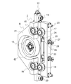
- FIG. 3 is a perspective view showing a detailed configuration of the processing apparatus main body 7 of FIG.
- FIG. 4 is a perspective view of the processing apparatus main body 7 of FIG. 3 viewed from an angle different from that of FIG.
- FIG. 5 is a perspective view of the processing apparatus main body 7 of FIG. 3 as viewed from an angle different from FIGS. 3 and 4.
- FIG. 6 is a perspective view of the processing apparatus main body 7 of FIG. 3 viewed from an angle different from that of FIGS.
- the processing apparatus main body 7 includes a frame 11, a connection tool 12, a processing tool 13, a processing tool driving device 14, a first guide roller 15, a second guide roller 16, a first pressing roller 17, and a second pressing roller 18. , A first front end roller 19 and a second front end roller 20.
- the frame 11 has a frame body 21 and a frame divided body 22.
- the connection tool 12, the processing tool 13, the processing tool driving device 14, the first guide roller 15, the second guide roller 16, the first tip roller 19, and the second tip roller 20 are attached to the frame body 21. Is provided.
- the first pressing roller 17 and the second pressing roller 18 are provided on the frame divided body 22.
- connection tool 12 is provided at the upper end of the frame main body 21.
- the suspension member 8 is connected to the connection tool 12.
- the processing tool driving device 14 is arranged on the frame body 21 on the side opposite to the processing tool 13.
- the processing tool driving device 14 rotates the processing tool 13.
- an electric motor is used as the processing tool driving device 14.
- the processing tool 13 processes the braking surface 2c.
- a grindstone is used as the processing tool 13.
- As the grindstone a cylindrical flat grindstone having a large number of abrasive grains on its outer peripheral surface is used. Further, a cutting tool or the like may be used as the processing tool 13.
- a cover (not shown) is provided on the frame body 21. When processing the braking surface 2c with the processing tool 13, processing chips are generated. The cover prevents the processing waste from scattering around the processing apparatus body 7.
- the first guide roller 15 and the second guide roller 16 are provided on the frame main body 21 alongside the processing tool 13. With the frame 11 suspended by the suspension member 8, the first guide roller 15 is disposed above the processing tool 13, and the second guide roller 16 is disposed below the processing tool 13. The processing tool 13 is arranged between the first guide roller 15 and the second guide roller 16.
- the first guide roller 15 and the second guide roller 16 contact the braking surface 2c together with the processing tool 13, thereby bringing the outer peripheral surface of the processing tool 13 into parallel contact with the braking surface 2c. That is, the outer peripheral surface of the processing tool 13 is brought into uniform contact with the braking surface 2c over the entire width direction of the processing tool 13.
- the two line segments that are the contact portions of the guide rollers 15 and 16 with the braking surface 2c and the one line segment that is the contact portion of the processing tool 13 with the braking surface 2c can exist in one plane. It is set as follows.
- the first pressing roller 17 sandwiches the guide portion 2b between the first pressing roller 17 and the first guide roller 15.
- the second pressing roller 18 sandwiches the guide 2 b between the second pressing roller 18 and the second guide roller 16. That is, when the processing tool 13, the first guide roller 15, and the second guide roller 16 come into contact with the braking surface 2c on the side to be processed, the first pressing roller 17 and the second pressing roller 18 Contacts the opposite braking surface 2c.
- the rotation axes of the processing tool 13 and the rollers 15, 16, 17, 18 are parallel or substantially parallel to each other, and are horizontal or substantially horizontal when the car guide rail 2 is processed.
- the first tip roller 19 is provided at the upper end of the frame main body 21.
- the second front end surface roller 20 is provided at a lower end of the frame main body 21. That is, the first and second front end surface rollers 19 and 20 are arranged at an interval in the vertical direction.
- the frame divided body 22 is linearly movable with respect to the frame body 21 between the sandwiching position and the release position.
- the sandwiching position is a position where the guide portion 2b is sandwiched between the guide rollers 15, 16 and the pressing rollers 17, 18.
- the release position is a position where the pressing rollers 17 and 18 are farther from the guide rollers 15 and 16 than the sandwiching position.
- the frame main body 21 is provided with a pair of rod-shaped frame guides 23.
- the frame guide 23 guides the movement of the frame divided body 22 with respect to the frame main body 21. Further, the frame guide 23 passes through the frame divided body 22.
- a pair of rod fixing portions 24 is provided on a surface of the frame main body 21 facing the frame divided body 22.
- a frame spring rod 26 is fixed to each rod fixing part 24. Each frame spring rod 26 passes through the frame divided body 22.
- a pair of first frame spring supports 25 is provided on the surface of the frame divided body 22 opposite to the frame body 21. Each frame spring rod 26 passes through a corresponding first frame spring receiver 25.
- a second frame spring receiver 27 is attached to the tip of each frame spring rod 26.
- a frame spring 28 is provided between each first frame spring receiver 25 and the corresponding second frame spring receiver 27. Each frame spring 28 generates a force to move the frame divided body 22 to the sandwiching position.
- the pressing force of the pressing rollers 17 and 18 by the frame spring 28 overcomes the force of the processing device body 7 tilting due to the eccentricity of the position of the center of gravity of the processing device body 7, and the outer peripheral surfaces of the guide rollers 15 and 16 and the braking surface 2c.
- the size is set so as to maintain the parallelism.
- the pressing force of the pressing rollers 17 and 18 by the frame spring 28 is not limited to the outer peripheral surface of the guide rollers 15 and 16 even when the processing apparatus main body 7 is moved along the car guide rail 2 while rotating the processing tool 13.
- the braking surface 2c are set to have such a size that the parallelism can be maintained.
- a release position holding mechanism (not shown) is provided between the frame main body 21 and the frame divided body 22.
- the release position holding mechanism holds the frame segment 22 in the release position against the spring force of the frame spring 28.
- the processing tool 13 and the processing tool driving device 14 can be moved linearly with respect to the frame body 21 between the processing position and the separation position.
- the processing position is a position where the processing tool 13 contacts the braking surface 2c in a state where the guide rollers 15, 16 contact the braking surface 2c.
- the separation position is a position where the processing tool 13 is separated from the braking surface 2c in a state where the guide rollers 15, 16 are in contact with the braking surface 2c.
- the pressing rollers 17, 18 are movable in a direction perpendicular to the braking surface 2c. Further, the processing tool 13 and the processing tool driving device 14 are also movable in a direction perpendicular to the braking surface 2c.
- the processing tool driving device 14 is fixed to a flat driving device supporting member 29 as a processing tool supporting member.
- the drive device support member 29 is detachably attached to the movable support member 30 by four fastening bolts 31.
- the number of fastening bolts 31 is not limited to four. However, in order to fix the driving device support member 29 and the movable support member 30 so that they cannot rotate with each other, the number of the fastening bolts 31 is desirably two or more.
- a pair of rod-shaped drive guides 32 are fixed to the frame body 21.
- the movable support member 30 is slidable along a drive guide 32. Thereby, the processing tool 13 and the processing tool driving device 14 can be moved linearly with respect to the frame main body 21.
- a processing tool spring 33 is provided between the movable support member 30 and the frame main body 21.
- the processing tool spring 33 generates a force for moving the processing tool 13 and the processing tool driving device 14 to the processing position.
- the pressing force of the processing tool 13 by the processing tool spring 33 is set to a size that does not cause a problem such as chatter.
- a separation position holding mechanism (not shown) is provided between the frame body 21 and the movable support member 30.
- the separation position holding mechanism holds the processing tool 13 and the processing tool driving device 14 at the separation position against the spring force of the processing tool spring 33.
- FIG. 7 is a perspective view showing a state in which the processing apparatus main body 7 of FIG. 3 is set on the car guide rail 2.
- FIG. 8 is a perspective view showing a state where the processing apparatus main body 7 of FIG. 4 is set on the car guide rail 2.
- FIG. 9 is a perspective view showing a state where the processing apparatus main body 7 of FIG. 5 is set on the car guide rail 2.
- FIG. 10 is a cross-sectional view of a main part of the processing apparatus main body 7 of FIG.
- the processing tool driving device 14 has a driving device main body 14a and a driving shaft 14b as a main shaft.
- the drive device main body 14a rotates the drive shaft 14b. That is, the drive shaft 14b is a rotation shaft of the processing tool drive device 14.
- the tip of the drive shaft 14b protrudes from the drive device main body 14a.
- the processing tool 13 is mechanically fixed to the distal end of the drive shaft 14b by a fastener.
- a fastener for example, a friction fastener for keylessly fixing the processing tool 13 to the drive shaft 14b is used.
- the frame body 21 is provided with a first hole 21a.
- the movable support member 30 is provided with a second hole 30a continuous with the first hole.
- Each of the first hole 21a and the second hole 30a has a size and a shape that allow the processing tool 13 to pass along the axial direction of the processing tool 13.
- the shape of the first and second holes 21a and 30a may be, for example, any of a circle, a square, and other polygons.
- the short side may be set to be the diameter of the processing tool 13 or more.
- the diameter of the first and second holes 21a and 30a may be larger than the diameter of the processing tool 13.
- the shape of the first hole 21a and the shape of the second hole 30a may be different from each other.
- the shape of the first hole 21a may be circular, and the shape of the second hole 30a may be square.
- the assembly 41 includes the processing tool 13, the processing tool driving device 14, and the driving device support member 29.
- the assembly 41 is detachable from the frame main body 21 in an assembled state. That is, the assembly 41 can be removed from the movable support member 30 in an integrated state by removing the fastening bolt 31. Further, the assembly 41 can be attached to the movable support member 30 in an integrated state by the fastening bolt 31.
- FIG. 11 is a cross-sectional view showing a contact state between the processing tool 13 and the car guide rail 2 in FIG.
- the width dimension of the outer peripheral surface of the processing tool 13 is larger than the width dimension of the braking surface 2c.
- the processing tool 13 is in contact with the entire braking surface 2c in the width direction.
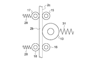
- FIG. 12 is a cross-sectional view showing a contact state between the first guide roller 15, the second guide roller 16, the first pressing roller 17, the second pressing roller 18, and the car guide rail 2 in FIG. is there.
- the outer peripheral surfaces of the first and second guide rollers 15 and 16 are cylindrical. That is, the outer peripheral surfaces of the first and second guide rollers 15, 16 in a cross section along the rotation center C1 of the first and second guide rollers 15, 16 are straight lines.
- the outer peripheral surfaces of the first and second pressing rollers 17 and 18 are spherical. That is, the outer peripheral surfaces of the first and second pressing rollers 17, 18 in a cross section along the rotation center C2 of the first and second pressing rollers 17, 18 are arc-shaped.
- FIG. 13 is a flowchart illustrating a guide rail machining method according to the first embodiment.
- step S1 is an operation at a site other than the site where the elevator is installed, and all other processes are operations at a site where the elevator is installed. Therefore, it is necessary to stop the operation of the target elevator while the processes other than step S1 are being performed.
- step S1 When processing the car guide rail 2 by the processing device body 7, first, in step S1, a plurality of assemblies 41 are assembled. In assembling the assemblies 41, the coaxiality between the processing tool 13 and the processing tool driving device 14 is adjusted.
- the processing tool 13 is mounted on the processing tool driving device 14 mounted on the driving device support member 29. Thereafter, the processing tool 13 is rotated by the processing tool driving device 14. At this time, the run-out of the processing tool 13 is measured using, for example, a dial gauge. Then, the position of the processing tool 13 is adjusted such that the deflection of the processing tool 13 is equal to or less than a specified value.
- the number of assemblies 41 to be prepared is proportional to the number of elevators to be machined and the lifting distance.
- One of the assemblies 41 is previously assembled to the movable support member 30 of the processing apparatus main body 7 with the fastening bolt 31.
- the guide rail processing device 100, a plurality of spare assemblies 41, a control device (not shown), and a power supply (not shown) are transported to the site where the elevator is installed.
- the control device is a device that controls the processing device main body 7.
- the control device and the power supply are carried into the car 3.
- the guide rail processing device 100 is loaded into the pit of the hoistway 1.
- step S5 the processing apparatus main body 7 is connected to the control device and the power supply. Then, in steps S6 and S7, the processing apparatus main body 7 is set on the car guide rail 2.
- step S6 in a state where the processing tool 13 is held at the separated position and the frame divided body 22 is held at the release position, the guide rollers 15, 16 are moved to one of the braking surfaces. 2c. Further, the front end rollers 19 and 20 are brought into contact with the front end face 2d.
- step S7 the frame divided body 22 is moved to the sandwiching position, and the guide portion 2b is sandwiched between the guide rollers 15, 16 and the pressing rollers 17, 18 as shown in FIG.
- step S8 After setting the processing apparatus main body 7 on the car guide rail 2 in this way, in step S8, the processing tool 13 is rotated. Then, in step S9, as shown in FIG. 16, the processing tool 13 and the processing tool driving device 14 are moved to the processing position, and the car 3 is moved to the top floor at a constant speed lower than the rated speed. That is, the processing apparatus body 7 is moved along the car guide rail 2 while processing the braking surface 2c by the processing tool 13.
- step S10 When the car 3 reaches the top floor, in step S10, the processing tool 13 and the processing tool driving device 14 are moved to the separated positions. In step S11, the rotation of the processing tool 13 is stopped, and the car 3 is stopped.
- step S12 the machining amount is measured while moving the car 3 to the lowest floor.
- the processing is performed on the braking surface 2c only when the car 3 is raised, it is preferable that the processing tool 13 is separated from the braking surface 2c when the car 3 is lowered.
- the measurement of the processing amount is performed by, for example, measuring the thickness dimension of the guide portion 2b or measuring the surface roughness of the braking surface 2c.
- step S13 it is checked whether the machining amount has reached a preset value. If the processing amount is sufficient, the processing is completed.
- step S14 If the processing amount is insufficient, the wear state of the processing tool 13 is checked in step S14. If the wear of the processing tool 13 has not progressed, the guide portion 2b is sandwiched between the guide rollers 15, 16 and the pressing rollers 17, 18, and steps S8 to S13 are performed again.
- step S15 If the wear of the processing tool 13 is progressing and a decrease in the processing efficiency is expected, the processing tool 13 is replaced in step S15. At this time, instead of replacing only the processing tool 13, the existing assembly 41 is replaced with a new assembly 41 having the same configuration in an assembled state.
- the existing assembly 41 is removed from the processing apparatus main body 7 in an integrated state. At this time, the existing assembly 41 is removed from the processing tool driving device 14 side of the processing tool 13 side and the processing tool driving device 14 side in the processing device main body 7. Thereafter, the new assembly 41 prepared in step S1 is attached to the processing apparatus body 7 and fixed with the fastening bolts 31.
- step S13 when the processing amount is sufficient, the processing is completed.
- a processing device body 7 that is symmetrical to that in FIG. 3 may be used, or the processing device body 7 in FIG. 3 may be suspended upside down. In the latter case, the connection tool 12 may be added to the lower end of the frame body 21.
- the guide rail machining method includes a suspension process, a machining process, and a replacement process.
- the processing apparatus body 7 is suspended in the hoistway 1 and set on the car guide rail 2.
- the processing apparatus main body 7 is suspended from the car 3 that moves up and down along the car guide rail 2.
- the car guide rail 2 is machined by the machining tool 13 while moving the machining apparatus body 7 along the car guide rail 2.
- the assembly 41 is replaced with a new assembly 41 in an assembled state.
- the existing car 3 and the existing safety device 5 are replaced with the new car and the new safety device while the existing car guide rail 2 is left. Further, the renewal method of the first embodiment includes a rail processing step and a replacement step.
- the processing apparatus main body 7 is connected to the existing car 3 via the suspension member 8, and the processing apparatus main body 7 is moved along the existing car guide rail 2 by moving the existing car 3.
- the replacement process is performed.
- the existing car 3 and the existing safety device 5 are replaced with the new car and the new safety device while leaving the existing car guide rails 2.
- the assembly 41 is detachable from the frame main body 21 in an assembled state. Therefore, adjustment of the coaxiality of the processing tool 13 with respect to the processing tool driving device 14 can be performed at a place other than the elevator installation site. In addition, the coaxiality can be easily reproduced when the processing tool 13 is replaced, and uniform processing accuracy can be secured over the entire processing section. In other words, thereby, the car guide rail 2 can be stably processed while the processing tool 13 is easily replaced.
- the assembly 41 of the first embodiment includes the processing tool 13, the processing tool driving device 14, and the driving device support member 29. For this reason, the configuration of the processing apparatus main body 7 is simplified, and the maintainability is improved.
- the frame main body 21 is provided with a first hole 21a through which the processing tool 13 can pass.
- the movable support member 30 is provided with a second hole 30a through which the processing tool 13 can pass, which is continuous with the first hole 21a. Therefore, with a simple configuration, the assembly 41 can be easily attached to and detached from the frame main body 21 while being integrated.
- the assembly 41 is replaced with a new assembly 41 in an assembled state. Therefore, the car guide rail 2 can be stably machined while easily exchanging the machining tool 13.
- the existing car may be replaced with the new car.
- the existing safety device mounted on the existing car is also replaced with a new safety device.
- the guide surface of the existing car guide rail may be worn due to long-term contact with the guide device mounted on the existing car, and the coefficient of friction with the emergency stop device may be reduced. For this reason, when replacing an existing car with a new car, the existing car guide rail is also replaced with the new car guide rail.
- the processing apparatus main body 7 is suspended in the hoistway 1 via the suspension member 8. Then, the processing apparatus main body 7 is moved along the car guide rail 2 while processing the braking surface 2 c by the processing tool 13. Therefore, the coefficient of friction of the car guide rail 2 with respect to the safety device 5 can be further optimized while the car guide rail 2 is installed in the hoistway 1.
- the braking surface 2c can be uniformly processed over substantially the entire length of the car guide rail 2.
- the processing apparatus body 7 is suspended by the suspension member 8. Therefore, it is possible to prevent the vibration of the car 3 from being transmitted to the processing device body 7 during the processing of the braking surface 2c. Thereby, it is possible to prevent the occurrence of a processing defect and to stably process the braking surface 2c.
- the processing device body 7 is suspended from the car 3. Therefore, it is not necessary to separately prepare a device for lifting the processing device main body 7. Moreover, the area
- the processing apparatus body 7 is provided with guide rollers 15 and 16. For this reason, the outer peripheral surface of the processing tool 13 can be more reliably brought into parallel contact with the braking surface 2c, and the braking surface 2c can be uniformly processed without generating uncut portions.
- the guide 2b is sandwiched between the guide rollers 15, 16 and the pressing rollers 17, 18. For this reason, the outer peripheral surface of the processing tool 13 can be more stably contacted in parallel with the braking surface 2c. Further, even when the braking surface 2c is vertically inclined, the outer peripheral surface of the processing tool 13 and the braking surface 2c can be kept parallel.
- the frame body 21 is provided with the connection tool 12. Therefore, the processing apparatus main body 7 can be moved along the car guide rail 2 in a state where the hanging member 8 is connected to the connecting tool 12 and is suspended in the hoistway 1. Thereby, the state of the car guide rail 2 with respect to the safety device 5 can be made more appropriate while the car guide rail 2 is installed in the hoistway 1.
- the first guide roller 15 is disposed above the processing tool 13, and the second guide roller 16 is disposed below the processing tool 13. Therefore, the parallelism between the outer peripheral surface of the processing tool 13 and the braking surface 2c can be more stably maintained. Accordingly, even when the car guide rail 2 is vertically inclined, bent, or undulated, the parallel relationship between the outer peripheral surface of the processing tool 13 and the braking surface 2c can be maintained.
- the processing tool 13 is disposed at an intermediate position between the first and second guide rollers 15 and 16. For this reason, the moving direction of the processing tool 13 with respect to the frame main body 21 can be set to a direction perpendicular to the braking surface 2c. Thereby, the force for pressing the processing tool 13 against the braking surface 2c can be stabilized. In addition, it is possible to perform stable processing without generating unevenness of processing, that is, non-uniformity of the shaving amount.
- the frame 11 is divided into a frame main body 21 and a frame divided body 22. Then, the frame spring 28 generates a force for moving the frame divided body 22 to the sandwiching position side. Therefore, the guide portion 2b can be stably sandwiched between the guide rollers 15, 16 and the pressing rollers 17, 18 with a simple configuration.
- the processing tool 13 and the processing tool driving device 14 are movable between a processing position and a separation position.
- the processing tool spring 33 generates a force to move the processing tool 13 and the processing tool driving device 14 to the processing position. Therefore, with a simple configuration, the processing tool 13 can be stably pressed against the braking surface 2c to perform stable processing. Further, by moving the processing tool 13 to the separated position, the processing apparatus main body 7 can be moved along the car guide rail 2 without processing the braking surface 2c.
- the frame body 21 is provided with front end surface rollers 19 and 20. Therefore, the processing apparatus main body 7 can be smoothly moved in a stable posture along the car guide rail 2.
- the outer peripheral surfaces of the guide rollers 15 and 16 are cylindrical, and the cross-sectional shapes of the outer peripheral surfaces of the pressing rollers 17 and 18 are arc-shaped. This automatically adjusts the outer peripheral surfaces of the guide rollers 15 and 16 to be parallel to the braking surface 2c.
- FIG. 19 is a perspective view showing the processing apparatus main body 7 of the guide rail processing apparatus according to Embodiment 2 of the present invention.
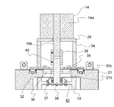
- FIG. 20 is a cross-sectional view of a main part of the processing apparatus main body 7 of FIG.
- the drive device support member 29 according to the second embodiment is fixed to the movable support member 30 via a plurality of, here four, support columns 34.
- the driving device support member 29 faces the movable support member 30.
- a bearing holding member 36 is fixed to the movable support member 30 by a plurality of fastening bolts 35.
- the bearing holding member 36 is in contact with the surface of the movable support member 30 opposite to the drive device support member 29.
- the working tool support member according to the second embodiment is a bearing holding member 36.
- a bearing 37 is held by the bearing holding member 36.
- the bearing 37 holds a main shaft 38.
- the main shaft 38 is rotatably held by a bearing holding member 36 via a bearing 37.
- the processing tool 13 is mechanically fixed to the first axial end of the main shaft 38 by a fastener.
- a fastener for example, a friction fastener for keylessly fixing the processing tool 13 to the main shaft 38 is used.
- the second end of the main shaft 38 in the axial direction is connected to the drive shaft 14b of the processing tool drive device 14 via a cylindrical coupling 39.
- the coupling 39 is fixed to the main shaft 38 and the drive shaft 14b by a plurality of set screws 40.
- the rotation of the drive shaft 14b is transmitted to the main shaft 38 and the processing tool 13 via the coupling 39.
- the main shaft 38 can be separated from the drive shaft 14b by loosening the set screw 40.
- the method of fixing the coupling 39 to the main shaft 38 and the drive shaft 14b is not limited to the fixing method using the set screw 40, and may be, for example, a slit type or a wedge type.
- the assembly 42 includes the processing tool 13, the bearing holding member 36, the bearing 37, and the main shaft 38.
- the assembly 42 is detachable from the frame main body 21 in an assembled state. That is, the assembly 41 can be detached from the movable support member 30 in an integrated manner by separating the main shaft 38 from the coupling 39 and removing the fastening bolt 35.
- the assembly 42 can be attached to the movable support member 30 in an integrated state by the fastening bolt 35.
- the main shaft 38 and the processing tool 13 are arranged on the axis of the drive shaft 14b.
- the frame main body 21 is provided with an accommodation hole 21b.
- the bearing holding member 36 is housed in the housing hole 21b.
- the diameter of the accommodation hole 21b is smaller than the diameter of the processing tool 13.
- the movable support member 30 is provided with a through hole 30b.
- the main shaft 38 is passed through the through hole 30b.
- the diameter of the through hole 30b is larger than the diameter of the main shaft 38 and smaller than the diameter of the housing hole 21b.
- a plurality of assemblies 42 are assembled in step S1 in FIG.
- the existing assembly 42 is removed from the processing tool 13 side of the processing apparatus body 7.
- the assembly 42 is detachable from the frame main body 21 in an assembled state. Therefore, the car guide rail 2 can be stably machined while easily exchanging the machining tool 13.
- the position of the center of rotation of the processing tool 13 in the processing apparatus body 7 is determined by the bearing 37. Therefore, by assembling the assembly 42 with high accuracy, the coaxiality between the processing tool 13 and the processing tool driving device 14 is maintained even when the assembly 42 is replaced. Thus, the processing tool driving device 14 can be left in the frame body 21 when the assembly 42 is replaced.
- the rigidity of the frame body 21 and the movable support member 30 can be increased. Thereby, highly accurate processing can be performed.
- the car guide rail 2 and the wall surface or the steel material to which the car guide rail 2 is fixed exist on the processing tool 13 side of the processing apparatus body 7. For this reason, it is desirable to appropriately select whether to remove the processing tool 13 from the processing tool driving device 14 side or the processing tool 13 side of the processing apparatus main body 7 according to the layout of the elevator installation site. .
- the force for pressing the processing tool and the pressing roller against the braking surface is generated by the spring, but may be generated by, for example, a pneumatic cylinder, a hydraulic cylinder, or an electric actuator.
- connection tool may be formed integrally with the frame.
- the processing apparatus main body is suspended from the existing car, but may be suspended from the new car.
- the main body of the processing apparatus is suspended from the car, but the main body of the processing apparatus may be suspended from a lifting device such as a winch installed on the hoistway or the car.
- the elevating body is a car and the object to be processed is a car guide rail has been described.
- the present invention can also be applied to a case where the lifting / lowering body is a counterweight and the object to be processed is a counterweight guide rail.
- the processing device main body may be suspended from the counterweight, or may be suspended from the lifting device.
- the processing is performed on the braking surface while raising the processing device main body, but the processing may be performed on the braking surface while lowering the processing device main body.
- the processing amount may be measured while raising the processing apparatus main body. Further, the processing and the measurement of the processing amount may be performed simultaneously.
- the car guide rail was processed during the renewal work.
- the present invention can also be applied to a case where it is desired to adjust the surface roughness of a braking surface in a newly installed elevator, or to refresh the braking surface during maintenance of an existing elevator.
- the present invention can be applied to various types of elevators such as an elevator having a machine room, a machine room-less elevator, a double deck elevator, and a one-shaft multi-car type elevator.
- the one-shaft multi-car system is a system in which an upper car and a lower car disposed directly below an upper car independently move up and down a common hoistway.
- the guide rail to be machined is not limited to an elevator guide rail, but may be a railroad rail, for example. In this case, the time required to stop the railway can be reduced.
Landscapes
- Lift-Guide Devices, And Elevator Ropes And Cables (AREA)
Abstract
L'invention concerne un dispositif d'usinage de rail de guidage dans lequel un corps de dispositif d'usinage comporte un cadre, un élément support d'outil d'usinage, une broche principale, un outil d'usinage et un dispositif d'entraînement d'outil d'usinage. La broche principale est montée à rotation sur l'élément support d'outil d'usinage. L'outil d'usinage est disposé sur la broche principale et tronçonne au moins une portion d'un rail de guidage. Le dispositif d'entraînement d'outil d'usinage fait tourner l'outil d'usinage. Un ensemble qui comprend l'élément support d'outil d'usinage, la broche principale et l'outil d'usinage est configuré pour pouvoir, dans l'état, être fixé au cadre et être détaché de celui-ci dans un état assemblé.
Priority Applications (3)
| Application Number | Priority Date | Filing Date | Title |
|---|---|---|---|
| PCT/JP2018/034247 WO2020054066A1 (fr) | 2018-09-14 | 2018-09-14 | Dispositif et procédé d'usinage de rail de guidage |
| JP2020546661A JP6980122B2 (ja) | 2018-09-14 | 2018-09-14 | ガイドレール加工装置及びガイドレール加工方法 |
| CN201880097203.3A CN112654574B (zh) | 2018-09-14 | 2018-09-14 | 导轨加工装置和导轨加工方法 |
Applications Claiming Priority (1)
| Application Number | Priority Date | Filing Date | Title |
|---|---|---|---|
| PCT/JP2018/034247 WO2020054066A1 (fr) | 2018-09-14 | 2018-09-14 | Dispositif et procédé d'usinage de rail de guidage |
Publications (1)
| Publication Number | Publication Date |
|---|---|
| WO2020054066A1 true WO2020054066A1 (fr) | 2020-03-19 |
Family
ID=69777711
Family Applications (1)
| Application Number | Title | Priority Date | Filing Date |
|---|---|---|---|
| PCT/JP2018/034247 Ceased WO2020054066A1 (fr) | 2018-09-14 | 2018-09-14 | Dispositif et procédé d'usinage de rail de guidage |
Country Status (3)
| Country | Link |
|---|---|
| JP (1) | JP6980122B2 (fr) |
| CN (1) | CN112654574B (fr) |
| WO (1) | WO2020054066A1 (fr) |
Cited By (1)
| Publication number | Priority date | Publication date | Assignee | Title |
|---|---|---|---|---|
| CN113401767A (zh) * | 2021-07-08 | 2021-09-17 | 重庆翰洲机电设备有限公司 | 一种电梯导轨支架预装设备 |
Families Citing this family (1)
| Publication number | Priority date | Publication date | Assignee | Title |
|---|---|---|---|---|
| CN114484170B (zh) * | 2022-01-21 | 2024-03-15 | 江苏海菱机电设备工程有限公司 | 一种废旧电梯回收卸载方法及辅助卸载装置 |
Citations (5)
| Publication number | Priority date | Publication date | Assignee | Title |
|---|---|---|---|---|
| JPH0660603U (ja) * | 1993-01-26 | 1994-08-23 | 西日本旅客鉄道株式会社 | レール磨き装置及び研磨具 |
| JPH08284102A (ja) * | 1995-04-11 | 1996-10-29 | Tohoku Giken Kogyo Kk | レール頭部継目溶接残部の研削装置 |
| JP2002052413A (ja) * | 2000-08-07 | 2002-02-19 | Hitachi Ltd | レール加工装置及びレール加工方法 |
| WO2011093002A1 (fr) * | 2010-01-29 | 2011-08-04 | 財団法人浜松科学技術研究振興会 | Dispositif d'alésage |
| JP2012091262A (ja) * | 2010-10-27 | 2012-05-17 | Senjo Seiki Kk | 加工装置 |
Family Cites Families (5)
| Publication number | Priority date | Publication date | Assignee | Title |
|---|---|---|---|---|
| CN1182941C (zh) * | 2000-11-30 | 2005-01-05 | 钱远强 | 现场研磨抛光机 |
| JP4220717B2 (ja) * | 2002-03-27 | 2009-02-04 | 三菱電機株式会社 | エレベータ用ガイドレールの加工方法 |
| CN1846918A (zh) * | 2005-07-12 | 2006-10-18 | 冯民堂 | 一种数控电火花曲面磨床 |
| CN2930956Y (zh) * | 2006-06-09 | 2007-08-08 | 孙忠成 | 车刀钻头刃磨器 |
| CN201077025Y (zh) * | 2007-09-15 | 2008-06-25 | 安庆机床有限公司 | 钢球光、磨、研机床双面磨板修正器 |
-
2018
- 2018-09-14 JP JP2020546661A patent/JP6980122B2/ja active Active
- 2018-09-14 CN CN201880097203.3A patent/CN112654574B/zh active Active
- 2018-09-14 WO PCT/JP2018/034247 patent/WO2020054066A1/fr not_active Ceased
Patent Citations (5)
| Publication number | Priority date | Publication date | Assignee | Title |
|---|---|---|---|---|
| JPH0660603U (ja) * | 1993-01-26 | 1994-08-23 | 西日本旅客鉄道株式会社 | レール磨き装置及び研磨具 |
| JPH08284102A (ja) * | 1995-04-11 | 1996-10-29 | Tohoku Giken Kogyo Kk | レール頭部継目溶接残部の研削装置 |
| JP2002052413A (ja) * | 2000-08-07 | 2002-02-19 | Hitachi Ltd | レール加工装置及びレール加工方法 |
| WO2011093002A1 (fr) * | 2010-01-29 | 2011-08-04 | 財団法人浜松科学技術研究振興会 | Dispositif d'alésage |
| JP2012091262A (ja) * | 2010-10-27 | 2012-05-17 | Senjo Seiki Kk | 加工装置 |
Cited By (2)
| Publication number | Priority date | Publication date | Assignee | Title |
|---|---|---|---|---|
| CN113401767A (zh) * | 2021-07-08 | 2021-09-17 | 重庆翰洲机电设备有限公司 | 一种电梯导轨支架预装设备 |
| CN113401767B (zh) * | 2021-07-08 | 2022-04-29 | 重庆翰洲机电设备有限公司 | 一种电梯导轨支架预装设备 |
Also Published As
| Publication number | Publication date |
|---|---|
| JP6980122B2 (ja) | 2021-12-15 |
| CN112654574B (zh) | 2022-06-03 |
| JPWO2020054066A1 (ja) | 2021-02-15 |
| CN112654574A (zh) | 2021-04-13 |
Similar Documents
| Publication | Publication Date | Title |
|---|---|---|
| JP6980122B2 (ja) | ガイドレール加工装置及びガイドレール加工方法 | |
| JP6765534B2 (ja) | エレベータのガイドレール加工方法、ガイドレール加工装置、及びリニューアル方法 | |
| CN111015445A (zh) | 一种箱式结构电梯曳引轮加工设备及其加工方法 | |
| JP6719686B2 (ja) | エレベータのガイドレール加工装置 | |
| JP7003290B2 (ja) | ガイドレール加工装置及びガイドレール加工方法 | |
| JP6821066B2 (ja) | エレベータのガイドレール加工装置及びガイドレール加工方法 | |
| JP6808052B2 (ja) | エレベータのガイドレール加工装置 | |
| EP2055662A1 (fr) | Rail de guidage pour ascenseur et dispositif de traitement de surface de rail surface pour ascenseur | |
| JP6862607B2 (ja) | エレベータのガイドレール加工方法 | |
| JP7008833B2 (ja) | エレベータのガイドレール加工装置及びガイドレール加工方法 | |
| JP6671566B1 (ja) | ガイドレール加工装置及びガイドレール加工方法 | |
| JPS6190802A (ja) | エレベ−タ用シ−ブの溝切削加工装置 | |
| CN112334272B (zh) | 电梯的导轨加工装置 | |
| WO2020161792A1 (fr) | Appareil d'usinage de rail de guidage et procédé d'usinage de rail de guidage |
Legal Events
| Date | Code | Title | Description |
|---|---|---|---|
| 121 | Ep: the epo has been informed by wipo that ep was designated in this application |
Ref document number: 18933553 Country of ref document: EP Kind code of ref document: A1 |
|
| ENP | Entry into the national phase |
Ref document number: 2020546661 Country of ref document: JP Kind code of ref document: A |
|
| NENP | Non-entry into the national phase |
Ref country code: DE |
|
| 122 | Ep: pct application non-entry in european phase |
Ref document number: 18933553 Country of ref document: EP Kind code of ref document: A1 |