WO2020054515A1 - Appareil de cuisson - Google Patents
Appareil de cuisson Download PDFInfo
- Publication number
- WO2020054515A1 WO2020054515A1 PCT/JP2019/034613 JP2019034613W WO2020054515A1 WO 2020054515 A1 WO2020054515 A1 WO 2020054515A1 JP 2019034613 W JP2019034613 W JP 2019034613W WO 2020054515 A1 WO2020054515 A1 WO 2020054515A1
- Authority
- WO
- WIPO (PCT)
- Prior art keywords
- lid
- cooking
- rice cooker
- main body
- unit
- Prior art date
- Legal status (The legal status is an assumption and is not a legal conclusion. Google has not performed a legal analysis and makes no representation as to the accuracy of the status listed.)
- Ceased
Links
Images


Classifications
-
- A—HUMAN NECESSITIES
- A47—FURNITURE; DOMESTIC ARTICLES OR APPLIANCES; COFFEE MILLS; SPICE MILLS; SUCTION CLEANERS IN GENERAL
- A47J—KITCHEN EQUIPMENT; COFFEE MILLS; SPICE MILLS; APPARATUS FOR MAKING BEVERAGES
- A47J27/00—Cooking-vessels
-
- H—ELECTRICITY
- H05—ELECTRIC TECHNIQUES NOT OTHERWISE PROVIDED FOR
- H05B—ELECTRIC HEATING; ELECTRIC LIGHT SOURCES NOT OTHERWISE PROVIDED FOR; CIRCUIT ARRANGEMENTS FOR ELECTRIC LIGHT SOURCES, IN GENERAL
- H05B6/00—Heating by electric, magnetic or electromagnetic fields
- H05B6/02—Induction heating
- H05B6/10—Induction heating apparatus, other than furnaces, for specific applications
- H05B6/12—Cooking devices
Definitions
- the present invention relates to a cooking device, and more particularly to a cooking device having an inner pot and using the inner pot with a lid.
- Patent Document 1 a rice cooker disclosed in Patent Document 1 is known as a rice cooker in which a rice cooker main body and a power supply unit can be separated.
- the operation panel for operating the rice cooker is generally mounted on a lid that covers the inner pot of the rice cooker main body. For this reason, when wiring for power supply and transmission / reception of various signals is formed between the lid and the rice cooker main body, there was no technical idea to provide an operation unit particularly on the rice cooker main body side. In a cooking device using such an inner pot, since cooking is generally performed with a lid, an operation panel is often provided not on the cooking device main body side but on the lid body side. Therefore, cooking cannot be performed with the lid completely removed from the cooking device body.
- One embodiment of the present invention realizes a cooking device that can perform cooking properly even when a lid is completely removed from the cooking device main body by providing an operation panel also on the cooking device main body side. With the goal.
- a cooker according to one embodiment of the present invention includes a cooker main body and an operation panel, covers the cooker main body, and is provided detachably from the cooker main body.
- the operation panel is provided on both the cooker main body and the lid.
- cooking can be appropriately performed on the cooking device main body side even when the lid is completely removed from the cooking device main body.
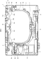
- FIG. 2 is a sectional view taken along line AA of FIG. It is a figure which shows the schematic structure of the rice cooker shown in FIG.
- FIG. 2 is a schematic block diagram of a control circuit on a lid main body side of the rice cooker shown in FIG. 1. It is a schematic block diagram of the control circuit of the cooker main body side of the rice cooker shown in FIG. It is a figure for explaining the cooking mode in the rice cooker concerning Embodiment 2 of the present invention.
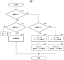
- 7 is a flowchart showing a flow of temperature control based on the presence or absence of an inner lid in the rice cooker shown in FIG.
- FIG. 1A and 1B show a rice cooker 1 according to the first embodiment, wherein FIG. 1A is a perspective view of the rice cooker with a lid attached thereto, and FIG. 1B is an exploded perspective view of the rice cooker of FIG.
- FIG. 2 is a cross-sectional view taken along line AA of FIG.
- the rice cooker 1 includes a rice cooker main body (cooker main body) 3 and a lid 2 attached to an upper portion of the rice cooker main body 3.
- the lid 2 can be completely separated from the rice cooker main body 3. That is, the lid 12 is provided detachably from the rice cooker main body 3.
- the rice cooker 1 is configured to be used not only for cooking rice but also for cooking such as boiled food and steamed food.
- the lid 2 is provided with a UI unit 8 for performing the rice cooking operation of the rice cooker 1.
- the UI unit 8 includes a display unit 8a formed of a liquid crystal display panel of a touch panel type, and an operation unit 8b including operation buttons operated by a user. Thereby, the user can perform the rice cooking operation of the rice cooker 1 by touching the operation buttons and the like displayed on the liquid crystal display panel.
- a touch panel type organic EL panel may be used instead of the touch panel type liquid crystal display panel.
- the UI unit 8 needs to supply and receive power and transmit and receive control signals for controlling the rice cooker 1. Power is supplied from the rice cooker body 3. In addition, transmission and reception of control signals are performed between the lid 2 and the rice cooker main body 3. Generally, these power supply and transmission / reception of the control signal are performed by wire. However, in the rice cooker 1 according to the present embodiment, since the lid 2 is configured to be completely separated from the rice cooker main body 3, transmission and reception of control signals such as power supply by wireless power supply and cooking signals by non-contact communication. It is supposed to do.
- the wireless power supply is performed between the wireless power supply unit 5a of the lid 2 and the wireless power supply unit 5b of the rice cooker main body 3, and the non-contact communication is performed by the non-contact communication unit 6a of the lid 2 and the non-contact communication of the rice cooker main body 3.
- the communication is performed with the contact communication unit 6b. Details of wireless power supply and non-contact communication will be described later.
- the lid 2 is composed of an outer lid 21 that covers the upper surface of the rice cooker main body 3 and an inner lid 22 that covers the inner pot 4.
- the inner lid 22 is formed completely independently of the outer lid 21, and when the outer lid 21 is removed from the rice cooker main body 3, the inner lid 4 is attached to the inner pot 4. The lid remains intact.
- the inner lid 22 is formed by aluminum die casting.
- the lid 2 When closing the rice cooker main body 3, the lid 2 is first set so as to cover the inner pot 4 with the inner lid 22 and cover the inner lid 22 with the outer lid 21 from above.
- a knob 23 projecting in a substantially cylindrical shape is formed so that the user can pinch it.
- the outer lid 21 has an opening into which the knob 23 of the inner lid 22 is fitted when the inner lid 22 is set at a predetermined position of the rice cooker main body 3 with the inner lid 4 covered. A part (not shown) is formed. That is, when the lid 2 is set on the rice cooker main body 3, the opening of the outer lid 21 is fitted into the knob 23 of the inner lid 22 covering the inner pot 4. This position is an appropriate position where the lid 2 is set on the rice cooker main body 3.
- the information displayed on the display unit 8a provided on the lid 2 and the transmission of the touched signal are transmitted by the non-contact communication between the lid 2 and the rice cooker main body 3 as described above.
- power is supplied to the UI unit 8 by wireless power supply between the lid 2 and the rice cooker main body 3 as described above.
- the lid 2 is provided with a wireless power supply unit 5a
- the rice cooker body 3 is provided with a wireless power supply unit 5b.
- the wireless power supply unit 5a and the wireless power supply unit 5b supply power to the lid 2 from the rice cooker main body 3 in a state where the lid 2 is set at a predetermined position of the rice cooker main body 3. It is provided at a position where it can be made.
- the non-contact communication part 6a is provided in the lid 2, and the non-contact communication part 6b is provided in the rice cooker main body 3, respectively.
- the non-contact communication section 6a and the non-contact communication section 6b are arranged between the lid 2 and the rice cooker main body 3 in a state where the lid 2 is set at a predetermined position of the rice cooker main body 3, as shown in FIG. Is provided at a position where information can be transmitted and received.
- an electromagnetic induction system is used for wireless power supply
- an infrared communication (IR) transmission system is used for non-contact communication.
- wireless power supply and non-contact communication are not limited to these methods, and power supply and information transmission / reception can be appropriately performed wirelessly with the lid 2 set at a predetermined position of the rice cooker main body 3. Any method may be used as long as it is a method.
- the rice cooker main body 3 is provided with an induction coil 7 for induction heating the inner pot 4 as shown in FIG.
- the induction coil 7 is an example of a heating unit.
- the rice cooker main body 3 has a cooling fan 9 for sending air to members requiring cooling such as a power supply, a power supply board 10, and a power supply cord wound around a cord reel so as to be drawn out.
- a bottom thermistor 12 for detecting the temperature of the inner pot 4 is provided.
- the inner pot 4 stores rice, water, and the like as an example of contents.
- the inner pot 4 is made of, for example, a high heat conductive material such as aluminum, and a magnetic material such as stainless steel for improving the heating efficiency is attached to the outer surface thereof, while the inner surface is coated with a fluororesin to prevent adhesion of contents. Have been.
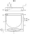
- FIG. 3 is a schematic diagram of the rice cooker 1 according to the present embodiment.
- the rice cooker body 3 is also provided with a UI unit (operation panel: display unit 24a, operation unit 24b) 24.
- the rice cooker 1 has the operation panels (UI unit 8 and UI unit 24) provided on both the lid 2 and the rice cooker main body 3.
- the operation of the UI unit 8 which is an operation panel provided on the lid 2 is performed by the UI unit 24 which is an operation panel provided on the rice cooker main body 3. Takes precedence over operation.
- the cooking menu set by the cooking set by the UI unit 8 of the lid 2 Is executed.
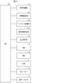
- FIG. 4 is a block diagram showing a configuration of a control circuit provided on the lid 2.
- FIG. 5 is a block diagram showing a configuration of a control circuit provided in rice cooker main body 3.
- the lid 2 includes a CPU 30, a ROM (Read Only Memory) 34, and a RAM (Random Access Memory) 35 as main parts of a control system. Further, the CPU 30 is connected to the cooking control unit 33, the non-contact communication unit 6a, the wireless power supply unit 5a, the communication state determination unit 31, the power measurement unit 32, and the UI unit 8.
- the CPU 30 is connected to the cooking control unit 33, the non-contact communication unit 6a, the wireless power supply unit 5a, the communication state determination unit 31, the power measurement unit 32, and the UI unit 8.
- the CPU 30 controls each unit by executing a control program stored in the ROM 34. Specifically, the CPU 30 controls display of the UI unit 8, reception of an operation, control for instructing the cooking control unit 33 to perform cooking control, determination of the communication state of the non-contact communication unit 6 a by the communication state determination unit 31, The power measurement unit 32 performs control for determining the power supply state of the wireless power supply unit 5a, and the like.
- the inner lid 22 is provided with a lid heater 13 for warming the lid itself and a lid thermistor 14 for measuring the temperature of the lid.
- the lid heater 13 and the lid thermistor 14 are connected to the CPU 30 and control the temperature of the lid heater 13.
- the rice cooker main body 3 includes a CPU 40, a ROM 44, and a RAM 45 as main components of a control system. Further, the CPU 40 is connected to the non-contact communication unit 6b, the wireless power supply unit 5b, the communication state determination unit 41, the induction coil 7, and the UI unit 24.
- the CPU 40 controls each unit by executing a control program stored in the ROM 44. Specifically, the CPU 40 receives the instruction signal from the cooking control unit 33 of the lid 2 by the non-contact communication unit 6b, thereby controlling the on / off of the induction coil 7 and the non-contact communication unit by the communication state determination unit 41.
- the communication control unit 6b controls the communication state of the wireless power supply unit 5b. Further, the CPU 40 performs display control of the UI unit 24, acceptance of operation, control for instructing the cooking control unit 33 to perform cooking control, and heating control by the induction coil 7 by the bottom thermistor 12.
- the power supply 42 is connected to the wireless power supply unit 5b.
- the power supply 42 realizes conversion from commercial power supplied by plugging a power cord, which can be pulled out to a cord reel built in the rice cooker main body 3 into an outlet in a home, into a voltage for wireless power supply. are doing.
- the UI unit 24 is also provided on the rice cooker main body 3, so that even when the lid 2 is removed from the rice cooker 1, The rice cooker 1 can be operated by using the UI unit 24 of the rice cooker main body 3.
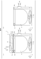
- FIGS. 6A and 6B are diagrams for explaining the cooking mode.
- FIG. 6A is a diagram for explaining the cooking mode A when the lid is attached to the rice cooker main body, and FIG. It is a figure for explaining cooking mode B at the time of having removed from.
- the UI unit 24 is provided in the rice cooker main body 3 in addition to the UI unit 8 of the lid 2.
- cooking mode A when lid 2 is attached to rice cooker main body 3 cooking mode with lid
- cooking mode B when lid 2 is removed from rice cooker main body 3. Cooking mode without lid
- the sequence of temperature control is as follows: the lid heater 13, the lid thermistor 14, the induction coil 7, the bottom thermistor. 15 is used.
- the temperature control sequence uses the induction coil 7 and the bottom thermistor 15. Therefore, it is necessary to prepare two types of temperature control sequences depending on the presence or absence of the lid, and switch and use them. That is, the rice cooker 1 in the present embodiment has different temperature control during cooking between the cooking mode with the lid and the cooking mode without the lid.
- FIG. 7 is a flowchart showing the flow of temperature control according to the presence or absence of a lid.
- the presence or absence of the outer lid 21 is determined (step S11).
- the presence or absence of the outer lid 21 is determined based on whether wireless power supply and non-contact communication between the outer lid 21 and the rice cooker main body 3 are possible.
- step S11 If it is determined in step S11 that the outer lid 21 is present (Yes), the process proceeds to step S12, and the presence or absence of the inner lid 22 is determined.
- the presence or absence of the inner lid 22 is determined by a magnet (not shown) provided in the inner lid 22 and a reed switch (not shown) provided in the rice cooker main body 3.
- step S13 normal cooking is performed (step S13).
- the normal cooking is realized by operating the UI unit 8 of the lid 2.
- the normal cooking is cooking in which temperature control during cooking is performed in the cooking mode with a lid (the same cooking as steps S16 and S17 described later).
- step S12 determines whether there is no inner lid 22 (No) or not.
- an error is displayed on the UI unit 8 (step S14). In this case, this is an error display for notifying the user that the inner lid 22 is not set. At the same time, a notification sound for notifying that cooking cannot be started without the inner lid 22 may be sounded.
- step S11 if it is determined that the outer lid 21 is not present (No), the process proceeds to step S15, and the presence or absence of the inner lid 22 is determined.
- the determination of the presence or absence of the inner lid 22 is also performed using a magnet and a reed switch, as in step S12.
- step S15 If it is determined in step S15 that the inner lid 22 is present (Yes), the sequence of mode A (cooking mode with lid) is used (step S16), and the temperature table of mode A is used (step S17) to cook. Temperature control.
- step S15 determines whether there is no inner lid 22 (No) or not.
- step S18 the sequence of mode B (cooking mode without lid) is used (step S18), and the temperature table of mode B is used (step S19). And control the temperature during cooking.
- the temperature table (first temperature table) is assumed to be hardly affected by the temperature outside the rice cooker body 3.
- the temperature control during cooking is performed by a temperature control sequence based on the temperature control.
- mode B which is the cooking mode without the lid
- the temperature control during cooking is performed by a temperature control sequence based on a temperature table (second temperature table) based on the assumption that the temperature is likely to be affected by the temperature outside the rice cooker main body 3. Will be performed.
- the temperature control based on the first temperature table is performed in the mode A that is the cooking mode with the lid, and the mode B that is the cooking mode without the lid is different from the first temperature table.
- Temperature control is performed based on the second temperature table. Specifically, the presence or absence of the lid 2 is detected, the first temperature table or the second temperature table is selected, and temperature control is performed based on the selected temperature table.
- an appropriate temperature table and a sequence of temperature control can be used in cooking in a case where both the outer lid 21 and the inner lid 22 of the lid 2 are not provided, so that the temperature outside the rice cooker main body 3 can be used. Temperature control during cooking can be appropriately performed without being affected by the above.
- the operation of the UI unit 8 of the lid 2 removed from the rice cooker main body 3 is not particularly described.
- the removed lid 2 is used as a remote controller for operating the rice cooker main body 3. May be.
- the lid 2 and the rice cooker main body 3 need to have a communication function such as infrared communication. Further, it is necessary to provide a power supply for causing the lid 2 to function as a communication function.
- the rice cooker main body 3 can be driven by operating the operation unit of the lid 2 in a state where the lid 2 is removed. Operation is possible without it.
- the set cooking mode is started by setting the lid 2 at a predetermined position of the rice cooker main body 3 as a trigger. You may do so.
- the cooking mode is the lidless cooking mode, and the rice cooker 2
- the cooking mode with the lid may be set. Switching between the cooking mode without the lid and the cooking mode with the lid may be performed by another method other than the method described above.
- the control block of the rice cooker 1 may be realized by a logic circuit (hardware) formed in an integrated circuit (IC chip) or the like, or may be realized by software.
- the rice cooker 1 includes a computer that executes instructions of a program that is software for realizing each function.
- This computer includes, for example, at least one processor (control device) and at least one computer-readable recording medium storing the program. Then, in the computer, the object of the present invention is achieved by the processor reading the program from the recording medium and executing the program.
- the processor for example, a CPU (Central Processing Unit) can be used.
- the recording medium include "temporary tangible media” such as ROM (Read Only Memory), tapes, disks, cards, semiconductor memories, and programmable logic circuits. Further, a RAM (Random Access Memory) for expanding the program may be further provided.
- the program may be supplied to the computer via an arbitrary transmission medium (a communication network, a broadcast wave, or the like) capable of transmitting the program.
- a transmission medium a communication network, a broadcast wave, or the like
- one embodiment of the present invention can also be realized in the form of a data signal embedded in a carrier wave, in which the above-described program is embodied by electronic transmission.
Landscapes
- Physics & Mathematics (AREA)
- Electromagnetism (AREA)
- Engineering & Computer Science (AREA)
- Food Science & Technology (AREA)
- Cookers (AREA)
Abstract
Dans la présente invention, la cuisson est effectuée de manière appropriée même dans un état dans lequel un corps de couvercle est complètement détaché d'un corps d'appareil de cuisson. Dans un appareil de cuisson (1), des parties UI (8, 24) permettant à un utilisateur de faire fonctionner l'appareil de cuisson (1) sont fournies à un corps de couvercle (2) et à un corps de cuiseur à riz (3), respectivement.
Applications Claiming Priority (2)
| Application Number | Priority Date | Filing Date | Title |
|---|---|---|---|
| JP2018169702 | 2018-09-11 | ||
| JP2018-169702 | 2018-09-11 |
Publications (1)
| Publication Number | Publication Date |
|---|---|
| WO2020054515A1 true WO2020054515A1 (fr) | 2020-03-19 |
Family
ID=69776562
Family Applications (1)
| Application Number | Title | Priority Date | Filing Date |
|---|---|---|---|
| PCT/JP2019/034613 Ceased WO2020054515A1 (fr) | 2018-09-11 | 2019-09-03 | Appareil de cuisson |
Country Status (2)
| Country | Link |
|---|---|
| TW (1) | TW202010455A (fr) |
| WO (1) | WO2020054515A1 (fr) |
Citations (8)
| Publication number | Priority date | Publication date | Assignee | Title |
|---|---|---|---|---|
| JPH02305520A (ja) * | 1989-05-19 | 1990-12-19 | Matsushita Electric Ind Co Ltd | 電気ジャー炊飯器 |
| JPH0476693B2 (fr) * | 1986-11-04 | 1992-12-04 | Matsushita Electric Ind Co Ltd | |
| JPH05285038A (ja) * | 1992-04-07 | 1993-11-02 | Sharp Corp | 加熱調理器 |
| JPH06319636A (ja) * | 1993-05-12 | 1994-11-22 | Matsushita Electric Ind Co Ltd | 炊飯器 |
| JPH08233287A (ja) * | 1995-02-24 | 1996-09-10 | Sanyo Electric Co Ltd | 調理器 |
| JP2004033405A (ja) * | 2002-07-02 | 2004-02-05 | Zojirushi Corp | 炊飯器の操作部 |
| JP2011160960A (ja) * | 2010-02-09 | 2011-08-25 | Tiger Vacuum Bottle Co Ltd | 電気炊飯器 |
| JP2018516714A (ja) * | 2015-12-28 | 2018-06-28 | 佛山市順徳区美的電熱電器制造有限公司 | 電気調理器用の無線給電通信回路、電気調理器及び無線給電通信方法 |
-
2019
- 2019-08-28 TW TW108130930A patent/TW202010455A/zh unknown
- 2019-09-03 WO PCT/JP2019/034613 patent/WO2020054515A1/fr not_active Ceased
Patent Citations (8)
| Publication number | Priority date | Publication date | Assignee | Title |
|---|---|---|---|---|
| JPH0476693B2 (fr) * | 1986-11-04 | 1992-12-04 | Matsushita Electric Ind Co Ltd | |
| JPH02305520A (ja) * | 1989-05-19 | 1990-12-19 | Matsushita Electric Ind Co Ltd | 電気ジャー炊飯器 |
| JPH05285038A (ja) * | 1992-04-07 | 1993-11-02 | Sharp Corp | 加熱調理器 |
| JPH06319636A (ja) * | 1993-05-12 | 1994-11-22 | Matsushita Electric Ind Co Ltd | 炊飯器 |
| JPH08233287A (ja) * | 1995-02-24 | 1996-09-10 | Sanyo Electric Co Ltd | 調理器 |
| JP2004033405A (ja) * | 2002-07-02 | 2004-02-05 | Zojirushi Corp | 炊飯器の操作部 |
| JP2011160960A (ja) * | 2010-02-09 | 2011-08-25 | Tiger Vacuum Bottle Co Ltd | 電気炊飯器 |
| JP2018516714A (ja) * | 2015-12-28 | 2018-06-28 | 佛山市順徳区美的電熱電器制造有限公司 | 電気調理器用の無線給電通信回路、電気調理器及び無線給電通信方法 |
Also Published As
| Publication number | Publication date |
|---|---|
| TW202010455A (zh) | 2020-03-16 |
Similar Documents
| Publication | Publication Date | Title |
|---|---|---|
| CN101589394B (zh) | 烹饪装置、烹饪装置的控制系统及烹饪装置的控制方法 | |
| US11644198B2 (en) | Terminal, cooking appliance communicating therewith and method of controlling cooking appliance | |
| JP6457294B2 (ja) | 加熱調理器 | |
| JP2019027705A (ja) | 加熱調理器 | |
| JPH11137421A (ja) | 電気炊飯器 | |
| KR20210085134A (ko) | 무선 유도가열 밥솥 및 이를 포함하는 무선 유도가열 시스템 | |
| JP6808055B2 (ja) | 電気炊飯器 | |
| JP2011004795A (ja) | 加熱装置および調理装置並びにこれらを備えた加熱調理器 | |
| JP2024144586A (ja) | 加熱調理器 | |
| JP5463626B2 (ja) | 電気炊飯器 | |
| CN109210583B (zh) | 控制方法、控制装置以及烹饪套装 | |
| CN112438584A (zh) | 压力烹饪器具及其控制方法和控制装置 | |
| TW202010455A (zh) | 調理器 | |
| JP2019154651A (ja) | 調理器 | |
| JP7756668B2 (ja) | 加熱調理器及び加熱調理システム | |
| JP6270906B2 (ja) | 温度検知装置および加熱調理器 | |
| JP7023748B2 (ja) | 調理器 | |
| JPWO2020054516A1 (ja) | 調理器 | |
| US20240155744A1 (en) | Heating cooker, computer program, and heating cooking method | |
| JP2005205060A (ja) | 電気炊飯器 | |
| JP5407532B2 (ja) | 調理家電 | |
| KR20250146900A (ko) | 조리 장치 | |
| CN209883853U (zh) | 烹饪器具 | |
| KR20250049165A (ko) | 조리기기 및 조리기기의 제어방법 | |
| CN110236402A (zh) | 烹调器 |
Legal Events
| Date | Code | Title | Description |
|---|---|---|---|
| 121 | Ep: the epo has been informed by wipo that ep was designated in this application |
Ref document number: 19861026 Country of ref document: EP Kind code of ref document: A1 |
|
| NENP | Non-entry into the national phase |
Ref country code: DE |
|
| 122 | Ep: pct application non-entry in european phase |
Ref document number: 19861026 Country of ref document: EP Kind code of ref document: A1 |
|
| NENP | Non-entry into the national phase |
Ref country code: JP |