WO2020054723A1 - Dispositif d'observation d'agression thermique, système d'endoscope, système d'observation d'agression thermique et procédé d'observation d'agression thermique - Google Patents
Dispositif d'observation d'agression thermique, système d'endoscope, système d'observation d'agression thermique et procédé d'observation d'agression thermique Download PDFInfo
- Publication number
- WO2020054723A1 WO2020054723A1 PCT/JP2019/035563 JP2019035563W WO2020054723A1 WO 2020054723 A1 WO2020054723 A1 WO 2020054723A1 JP 2019035563 W JP2019035563 W JP 2019035563W WO 2020054723 A1 WO2020054723 A1 WO 2020054723A1
- Authority
- WO
- WIPO (PCT)
- Prior art keywords
- information
- image data
- invasion
- fluorescence
- heat
- Prior art date
- Legal status (The legal status is an assumption and is not a legal conclusion. Google has not performed a legal analysis and makes no representation as to the accuracy of the status listed.)
- Ceased
Links
Images





Classifications
-
- A—HUMAN NECESSITIES
- A61—MEDICAL OR VETERINARY SCIENCE; HYGIENE
- A61B—DIAGNOSIS; SURGERY; IDENTIFICATION
- A61B1/00—Instruments for performing medical examinations of the interior of cavities or tubes of the body by visual or photographical inspection, e.g. endoscopes; Illuminating arrangements therefor
- A61B1/00002—Operational features of endoscopes
- A61B1/00004—Operational features of endoscopes characterised by electronic signal processing
- A61B1/00009—Operational features of endoscopes characterised by electronic signal processing of image signals during a use of endoscope
-
- A—HUMAN NECESSITIES
- A61—MEDICAL OR VETERINARY SCIENCE; HYGIENE
- A61B—DIAGNOSIS; SURGERY; IDENTIFICATION
- A61B1/00—Instruments for performing medical examinations of the interior of cavities or tubes of the body by visual or photographical inspection, e.g. endoscopes; Illuminating arrangements therefor
- A61B1/04—Instruments for performing medical examinations of the interior of cavities or tubes of the body by visual or photographical inspection, e.g. endoscopes; Illuminating arrangements therefor combined with photographic or television appliances
- A61B1/043—Instruments for performing medical examinations of the interior of cavities or tubes of the body by visual or photographical inspection, e.g. endoscopes; Illuminating arrangements therefor combined with photographic or television appliances for fluorescence imaging
-
- A—HUMAN NECESSITIES
- A61—MEDICAL OR VETERINARY SCIENCE; HYGIENE
- A61B—DIAGNOSIS; SURGERY; IDENTIFICATION
- A61B1/00—Instruments for performing medical examinations of the interior of cavities or tubes of the body by visual or photographical inspection, e.g. endoscopes; Illuminating arrangements therefor
- A61B1/00002—Operational features of endoscopes
- A61B1/00004—Operational features of endoscopes characterised by electronic signal processing
- A61B1/00009—Operational features of endoscopes characterised by electronic signal processing of image signals during a use of endoscope
- A61B1/000094—Operational features of endoscopes characterised by electronic signal processing of image signals during a use of endoscope extracting biological structures
-
- A—HUMAN NECESSITIES
- A61—MEDICAL OR VETERINARY SCIENCE; HYGIENE
- A61B—DIAGNOSIS; SURGERY; IDENTIFICATION
- A61B1/00—Instruments for performing medical examinations of the interior of cavities or tubes of the body by visual or photographical inspection, e.g. endoscopes; Illuminating arrangements therefor
- A61B1/00163—Optical arrangements
- A61B1/00186—Optical arrangements with imaging filters
-
- A—HUMAN NECESSITIES
- A61—MEDICAL OR VETERINARY SCIENCE; HYGIENE
- A61B—DIAGNOSIS; SURGERY; IDENTIFICATION
- A61B1/00—Instruments for performing medical examinations of the interior of cavities or tubes of the body by visual or photographical inspection, e.g. endoscopes; Illuminating arrangements therefor
- A61B1/06—Instruments for performing medical examinations of the interior of cavities or tubes of the body by visual or photographical inspection, e.g. endoscopes; Illuminating arrangements therefor with illuminating arrangements
- A61B1/0638—Instruments for performing medical examinations of the interior of cavities or tubes of the body by visual or photographical inspection, e.g. endoscopes; Illuminating arrangements therefor with illuminating arrangements providing two or more wavelengths
-
- A—HUMAN NECESSITIES
- A61—MEDICAL OR VETERINARY SCIENCE; HYGIENE
- A61B—DIAGNOSIS; SURGERY; IDENTIFICATION
- A61B1/00—Instruments for performing medical examinations of the interior of cavities or tubes of the body by visual or photographical inspection, e.g. endoscopes; Illuminating arrangements therefor
- A61B1/06—Instruments for performing medical examinations of the interior of cavities or tubes of the body by visual or photographical inspection, e.g. endoscopes; Illuminating arrangements therefor with illuminating arrangements
- A61B1/0655—Control therefor
-
- A—HUMAN NECESSITIES
- A61—MEDICAL OR VETERINARY SCIENCE; HYGIENE
- A61B—DIAGNOSIS; SURGERY; IDENTIFICATION
- A61B18/00—Surgical instruments, devices or methods for transferring non-mechanical forms of energy to or from the body
- A61B18/04—Surgical instruments, devices or methods for transferring non-mechanical forms of energy to or from the body by heating
- A61B18/12—Surgical instruments, devices or methods for transferring non-mechanical forms of energy to or from the body by heating by passing a current through the tissue to be heated, e.g. high-frequency current
- A61B18/14—Probes or electrodes therefor
- A61B18/148—Probes or electrodes therefor having a short, rigid shaft for accessing the inner body transcutaneously, e.g. for neurosurgery or arthroscopy
-
- A—HUMAN NECESSITIES
- A61—MEDICAL OR VETERINARY SCIENCE; HYGIENE
- A61B—DIAGNOSIS; SURGERY; IDENTIFICATION
- A61B17/00—Surgical instruments, devices or methods
- A61B2017/00017—Electrical control of surgical instruments
- A61B2017/00022—Sensing or detecting at the treatment site
- A61B2017/00057—Light
- A61B2017/00061—Light spectrum
-
- A—HUMAN NECESSITIES
- A61—MEDICAL OR VETERINARY SCIENCE; HYGIENE
- A61B—DIAGNOSIS; SURGERY; IDENTIFICATION
- A61B17/00—Surgical instruments, devices or methods
- A61B2017/00017—Electrical control of surgical instruments
- A61B2017/00115—Electrical control of surgical instruments with audible or visual output
- A61B2017/00128—Electrical control of surgical instruments with audible or visual output related to intensity or progress of surgical action
-
- A—HUMAN NECESSITIES
- A61—MEDICAL OR VETERINARY SCIENCE; HYGIENE
- A61B—DIAGNOSIS; SURGERY; IDENTIFICATION
- A61B18/00—Surgical instruments, devices or methods for transferring non-mechanical forms of energy to or from the body
- A61B2018/00571—Surgical instruments, devices or methods for transferring non-mechanical forms of energy to or from the body for achieving a particular surgical effect
- A61B2018/00595—Cauterization
-
- A—HUMAN NECESSITIES
- A61—MEDICAL OR VETERINARY SCIENCE; HYGIENE
- A61B—DIAGNOSIS; SURGERY; IDENTIFICATION
- A61B18/00—Surgical instruments, devices or methods for transferring non-mechanical forms of energy to or from the body
- A61B2018/00636—Sensing and controlling the application of energy
- A61B2018/00773—Sensed parameters
-
- A—HUMAN NECESSITIES
- A61—MEDICAL OR VETERINARY SCIENCE; HYGIENE
- A61B—DIAGNOSIS; SURGERY; IDENTIFICATION
- A61B18/00—Surgical instruments, devices or methods for transferring non-mechanical forms of energy to or from the body
- A61B2018/00636—Sensing and controlling the application of energy
- A61B2018/00773—Sensed parameters
- A61B2018/00791—Temperature
-
- A—HUMAN NECESSITIES
- A61—MEDICAL OR VETERINARY SCIENCE; HYGIENE
- A61B—DIAGNOSIS; SURGERY; IDENTIFICATION
- A61B18/00—Surgical instruments, devices or methods for transferring non-mechanical forms of energy to or from the body
- A61B18/04—Surgical instruments, devices or methods for transferring non-mechanical forms of energy to or from the body by heating
- A61B18/12—Surgical instruments, devices or methods for transferring non-mechanical forms of energy to or from the body by heating by passing a current through the tissue to be heated, e.g. high-frequency current
- A61B18/14—Probes or electrodes therefor
- A61B2018/1405—Electrodes having a specific shape
- A61B2018/1412—Blade
Definitions
- the present invention relates to a heat invasion observation apparatus, an endoscope system, a heat invasion observation system, and a heat invasion observation method for visualizing a cauterized state of a living tissue or the like using an energy device or the like.
- endoscope videoscope systems equipped with a special light observation function of controlling the wavelength of light and highlighting an observation target have been generally put to practical use in medical endoscopes mainly used in the medical field. I have.
- a narrow-band light observation (NBI: Narrow Band Imaging) function is to emit light of two narrow bands (390 to 445 nm / 530 to 550 nm) which are easily absorbed by hemoglobin in blood. Irradiation is performed on a subject (hereinafter, simply referred to as a subject), thereby realizing a highlighted display of capillaries on the surface of the mucous membrane and a fine pattern of the mucous membrane.
- IRI Infrared light observation
- the fluorescence observation (AFI: Auto Fluorescence Imaging) function uses excitation light (390 to 470 nm) for observing auto-fluorescence from living tissue and light of a wavelength (540 to 560 nm) absorbed by hemoglobin in blood. By irradiating the subject, it is possible to highlight the neoplastic lesion and the normal mucosa in different colors. That is, the fluorescence observation (AFI) function is a technique capable of highlighting a tumorous lesion and normal tissue in different colors by observing autofluorescence from a living mucous membrane.
- Japanese Patent Publication No. 10-505768 discloses the range and depth of skin burn injury using induced fluorescence spectroscopy with ultraviolet or blue light, and reflection spectroscopy of visible and infrared light.
- a burn injury evaluation device and a method for evaluating the same, which can be quickly evaluated by a doctor.
- This burn injury evaluation apparatus includes a plurality of light sources each of which emits excitation light having a plurality of predetermined wavelengths, a sensor for measuring a response light amount emitted from these light sources and reflected by a subject, and a microprocessor. And the like, and are configured to optically evaluate the skin at the burn site.
- Japanese Patent Publication No. 2012-130506 discloses an electronic endoscope system as an optical measurement system in which the probability of estimating the concentration of a light-absorbing component is increased, and an optical measurement method thereof.
- This electronic endoscope system irradiates a subject with excitation light to excite an infrared indicator drug (Indocyanine green: ICG (Indocyanine green)) injected into a blood vessel, and obtains an image obtained by imaging the same.
- ICG Indocyanine green
- the depth of a blood vessel from the surface of the subject can be estimated based on the signal.
- Japanese Patent Laid-Open Publication No. 2008-229025 discloses a fluorescent image that can accurately diagnose a lesion by accurately correcting fluorescence image data acquired using a fluorescence observation function. An observation device is disclosed.
- any of the devices disclosed in Japanese Patent Publication No. 10-505768, Japanese Patent Publication No. 2012-130506, Japanese Patent Publication No. 2008-229025, and the like all use special light observation. Based on image data acquired using the function, information that cannot be obtained by visual observation among information on the lesion, such as depth information of the lesion, is evaluated and estimated. Therefore, these conventional techniques have a problem in that it is not always possible to always reliably obtain high-accuracy information on information relating to a lesion.
- LCS Laparoscopy and Endoscopy Cooperative Surgery
- NEWS Non-exposed Endoscopic Wall-inversion Surgery
- ESD Endoscopy Submucosal Dissection
- a thermal invasive operation on a subject such as a living tissue is performed using an energy device such as an electric scalpel for marking of an operation target region.
- an energy device such as an electric scalpel for marking of an operation target region.
- excision or the like of a diseased body tissue is performed using an energy device such as the electric scalpel.
- the degree of thermal invasion applied to a desired part of the subject by the energy device is actually checked by an operator such as a doctor by visual observation, tactile sensation, intuition, or the like.
- the subject to which the heat invasion has been applied is a white tissue such as fat
- the present invention has been made in view of the above points, and an object of the present invention is to provide a heat invasive observation apparatus for visualizing a cauterized state of a subject such as a living tissue using an energy device, etc.
- a mirror system, a heat invasion observation system, and a heat invasion observation method are provided.
- a heat invasion observation device is a heat invasion observation device for observing heat invasion into a living tissue, and is used to excite a substance contained in a heat invasion region.
- a fluorescence image generation unit that obtains an imaging signal generated by imaging fluorescence generated from a heat invasive region in a living tissue irradiated with excitation light, and generates fluorescence image data based on the obtained imaging signal, Is provided.
- An endoscope system is an endoscope system for observing AGEs (end-glycation products) contained in a living tissue, and is a light source capable of generating excitation light for exciting AGEs.
- An imaging unit that obtains fluorescence generated from the AGEs irradiated with the excitation light to generate an imaging signal, and an image generation unit that generates the fluorescence image data based on the imaging signal.
- a heat invasion observation system is a heat invasion observation system for observing heat invasion of a living tissue, and a light source unit that generates excitation light for exciting a substance contained in the heat invasion region.
- An imaging unit that captures fluorescence generated from a heat-invasive region in a living tissue irradiated with excitation light to generate an imaging signal; and, based on an imaging signal generated by imaging the fluorescence by the imaging unit, generates fluorescence image data.
- a fluorescent image generating unit that generates
- a heat invasion observation method is a heat invasion observation method for observing heat invasion of a living tissue, and generates excitation light for exciting a substance contained in the heat invasion region,
- the imaging unit generates an imaging signal by imaging the fluorescence generated from the heat invasive region in the living tissue irradiated with the image, and generates the fluorescence image data based on the imaging signal generated by imaging the fluorescence by the imaging unit.
- a heat invasion observation apparatus an endoscope system, a heat invasion observation system, and a heat invasion observation method for visualizing a cauterized state of a subject such as a living tissue using an energy device or the like.
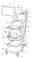
- FIG. 1 is an external perspective view illustrating an entire configuration of an endoscope system that is a heat invasive observation device according to an embodiment of the present invention.
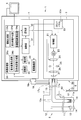
- 1 is a block diagram showing a schematic configuration of the endoscope system of FIG.
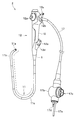
- FIG. 1 is an external perspective view showing an endoscope included in the endoscope system of FIG. 1.
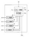
- FIG. 2 is a main block diagram showing a detailed configuration of a control unit of the light source device of the endoscope system in FIG. 1. The figure which shows the 1st modification about display of the marking area
- FIG. 9 shows a second modified example of a display example when a subject is cauterized by heat invasion using the endoscope system of the present embodiment and the subject including the cauterized region is observed in the fluorescence observation mode.
- Figure The figure which shows the example of a display which displays the depth of the heat invasion estimated from the result calculated using the heat invasion depth information among the fluorescence intensity information contained in the fluorescence image data of FIG.
- Third modification of a display example when a subject is cauterized by heat invasion using the endoscope system according to the embodiment of the present invention and the subject including the cauterized region is observed in the fluorescence observation mode.
- Diagram showing an example of an example The figure which shows another example of the 3rd modification of the display example in the endoscope system of one Embodiment of this invention.
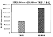
- Fig. 7 is a graph showing the fluorescence intensity on a living tissue when irradiating excitation light having a wavelength of 340 nm and observing fluorescence at a wavelength of 480 nm (in the case of a wavelength suitable for visualizing a heat invasive region).
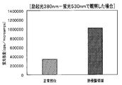
- FIG. 6 is a graph showing the fluorescence intensity on a living tissue when irradiating excitation light having a wavelength of 380 nm and performing fluorescence observation at a wavelength of 530 nm (in the case of a wavelength suitable for visualizing a heat invasive region).
- FIG. 6 is a graph showing the fluorescence intensity on a living tissue when irradiating excitation light having a wavelength of 380 nm and performing fluorescence observation at a wavelength of 530 nm (in the case of a wavelength suitable for visualizing a heat invasive region).
- FIG. 6 is a graph showing the fluorescence intensity on a living tissue when irradiating excitation light having a wavelength of 440 nm and performing fluorescence observation at a wavelength of 550 nm (in the case of a wavelength suitable for visualizing a heat invasive region).
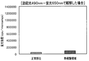
- FIG. 4 is a graph showing the fluorescence intensity on a living tissue when irradiating excitation light having a wavelength of 490 nm and observing fluorescence at a wavelength of 650 nm (in a case where the wavelength is not suitable for visualizing a heat invasion region)
- the thermal invasion observation apparatus performs a normal white light observation (WLI) and a special white light observation (WLI) on a region where a subject such as a living tissue is subjected to a thermal invasion such as cauterization using an energy device or the like.
- Light observation fluorescence observation
- Fluorescence observation is performed to acquire normal white light image data and fluorescence image data including fluorescence intensity information, and a predetermined form is obtained based on the acquired white light image data and fluorescence image data.
- Display image data is generated, and an image represented by the display image data is displayed in various display forms using a display unit (monitor).
- the thermal invasion observation apparatus of the present invention can clearly visualize the thermal invasion region by cauterization.
- a medical endoscope system mainly used in the medical field will be exemplified as an example of the thermal invasive observation device.
- FIG. 1 is an external perspective view showing an entire configuration of an endoscope system which is a heat invasive observation device according to an embodiment of the present invention.
- FIG. 2 is a block diagram showing a schematic configuration of the endoscope system of FIG.
- FIG. 3 is an external perspective view showing an endoscope included in the endoscope system of FIG.
- FIG. 4 is a main part block configuration diagram illustrating a detailed configuration of a control unit of the light source device of the endoscope system in FIG. 1.
- an endoscope system 1 including a heat invasive observation device includes an endoscope 2, a light source device 3, a video processor 4, a monitor 5, It has a medical trolley 6 (not shown in FIG. 2) for holding them.
- the endoscope 2 mainly includes an elongated insertion section 11, an operation section 12, a universal cable 17, an endoscope connector 17b, and the like. I have.
- the insertion portion 11 is a tubular member formed into an elongated tube shape and inserted into the subject.
- the insertion portion 11 is formed by sequentially connecting a distal end portion 11a, a curved portion 11b, and a flexible tube portion 11c from the distal end side, and has flexibility as a whole.
- the distal end portion 11a includes an image pickup device 13 having an image sensor such as a CCD therein, an objective optical system 14 for forming an optical image of a subject on the image pickup device 13, and an insertion portion.
- One end of a light guide 15, which is an optical fiber inserted into the section 11, and an illumination optical system 16 as an irradiation section for irradiating illumination light guided by the light guide 15 toward an observation target (subject) Etc. are arranged.
- the bending portion 11b receives a turning operation of a bending operation lever 12a that is a bending operation member for performing a bending operation among a plurality of operation members (described later) provided in the operation portion 12, and moves up and down (UP and DOWN).
- This is a mechanism unit configured to be able to bend actively in two directions.
- the form of the bending portion in the endoscope to which the present invention can be applied is not limited to the above-described example (a type capable of bending in two directions), and includes a horizontal direction in addition to the vertical direction. And the like that can be bent in four directions including the vertical direction and the left and right directions (UP and DOWN and RIGHT and LEFT) in different directions. May be.
- the flexible tube portion 11c is a tubular member formed to have flexibility so as to be passively flexible. Inside the flexible tube portion 11c, in addition to a treatment tool insertion channel (not shown), the flexible tube portion extends from the image pickup device 13 built in the distal end portion 11a, passes through the inside of the operation portion 12, and enters the inside of the universal cable 17.
- a light guide 15 that guides various kinds of electric signal lines 13a extending therefrom and light emitted from a light source device 3 (described later) as an external device to an illumination optical system 16 provided on the distal end surface of the distal end portion 11a. Etc. are inserted.
- the operation unit 12 is a constituent unit that is provided continuously with the base end of the insertion unit 11 and includes a plurality of operation members and the like.
- the operation unit 12 includes a fold prevention unit 9, a grip unit 10, a plurality of operation members (12a, 12b, etc.), a treatment tool insertion unit 12d, a suction valve 12c, and the like.
- the buckling prevention portion 9 is provided at a connection portion between the distal end portion of the operation portion 12 and the base end portion of the flexible tube portion 8, and covers the base end portion of the flexible tube portion 8, whereby the endoscope 2 of the endoscope 2 is covered. It is a protective member for preventing the flexible tube portion 8 from being unnecessarily sharply broken during use.
- the grip 10 is a housing that stores various components therein.
- the grip 10 is connected to the buckling stopper 9.
- the grip 10 is a part that is held by the user (user) when the endoscope 2 is used.
- the treatment tool insertion section 12d has a treatment tool insertion port (not shown) for inserting various treatment tools (not shown), and has a treatment tool insertion passage communicating with a treatment tool insertion channel inside the operation section 12. It is a component.
- the treatment instrument insertion portion 12d is provided with a forceps stopper 12e which is a lid member for opening and closing the treatment instrument insertion opening and which is detachably attached to the treatment instrument insertion portion 12d.
- the operation unit 12 is provided with a bending operation lever 12a, various switches 12b, a suction valve 12c, and the like.
- the bending operation lever 12a is an operation member for performing the bending operation of the bending portion 11b.
- the various switches 12b include, for example, an operation member for performing an air / water supply operation and a suction operation, and an operation member for performing an operation corresponding to each of the imaging unit and the illumination unit.
- the suction valve 12c is a connecting portion for connecting a suction pipe line to a suction device (not shown).
- a universal cable 17 extends from the base end side of the operation unit 12.
- the universal cable 17 is a hollow tubular member having flexibility and extending from the operation unit 12. As shown in FIG. 2, the universal cable 17 is a composite cable into which the light guide 15, the electric signal line 13a extending from the image sensor 13, and the like are inserted.
- a connector 17b serving as a connection terminal with another device is provided at the extending end of the universal cable 17.
- the connector 17b has a light source connector 17a detachably connected to the light source device 3 at the distal end side, and an air / water supply tube (not shown) from an air / water supply device (not shown) which is an external device. Are provided (see FIGS. 1 to 3).
- the connector 17b is connected to an electric connector 17c (see FIGS. 2 and 3) to which a scope cable 18 (see FIGS. 1 and 2; not shown in FIG. 3) that is electrically connected to the electric signal line 13a is connected. Is provided.
- a signal connector 18a (see FIG. 2) which is detachably connected to the video processor 4 is provided at an extending end of the scope cable 18.
- the light source device 3 is a light source unit having a function of separately generating excitation light and white light as illumination light for irradiating an observation target (subject).
- the light source device 3 includes a control unit 21, a front panel 22, a lamp 23 as a light source, a first rotary filter 24, a diaphragm device 25, a second rotary filter 26, It has a lens 27 and the like.
- the control unit 21 controls the entire light source device 3 and controls the lamp 23 and the aperture device 25 based on a signal regarding brightness from the video processor 4.
- the control unit 21 includes a central processing unit (CPU), a ROM, a RAM, and the like. The detailed configuration of the control unit 21 will be described later.
- an observation mode changeover switch 22a for switching various observation modes (white light (normal light) observation mode, fluorescence (special light) observation mode, marking confirmation mode, etc.), and other various operation switches are provided. (Not shown).
- An operation signal from the front panel 22 is input to the control unit 21.
- the observation mode changeover switch 22a is a changeover switch for instructing switching between an illumination mode corresponding to the normal light observation mode and an illumination mode corresponding to the special light observation mode.
- the light source device 3 is configured to generate at least white light for normal light observation and excitation light that is a specific wavelength band light for special light observation.
- the lamp 23 is a light source for supplying illumination light to the subject, and for example, a xenon lamp or the like is applied. On / off control of the lamp 23 is performed according to a drive signal from the control unit 21.
- the first rotation filter 24 is a filter for selectively emitting either the wavelength band light for normal light observation or the wavelength band light for special light observation.
- the first rotation filter 24 is rotated around the rotation axis of the first rotation filter 24 based on a control signal from the control unit 21 to switch a filter corresponding to the mode designated by the observation mode changeover switch 22a to a lamp. It operates so as to be arranged on the optical path of the outgoing light of 23.
- the first rotary filter 24 is provided so as to be freely inserted into and removed from the optical path of the light emitted from the lamp 23, and when inserted in the optical path, a part of the light in the normal light observation mode in the special light observation mode.
- This is an optical filter that transmits band light.
- the light source is constituted by the lamp 23 and the optical filter of the first rotating filter 24. That is, in the special light observation mode, the light source device 3 causes the optical filter to be inserted into the optical path, and supplies the light transmitted through the optical filter to the light guide 15 as illumination light.
- the aperture device 25 is a light amount adjusting device that adjusts the emitted light amount of the illumination light supplied to the light guide 15.
- the diaphragm device 25 is driven in a direction to close or open the diaphragm based on a diaphragm drive signal from the control unit 21, so that the amount of light emitted from the lamp 23 is adjusted.
- the second rotating filter 26 is a filter unit configured to include, for example, an R (red) filter, a G (green) filter, and a B (blue) filter in order to emit light sequentially in a plane.
- the second rotation filter 26 rotates at a predetermined rotation speed around the rotation axis of the second rotation filter 26 based on the control signal from the control unit 21, and sequentially passes the three RGB filters on the optical path of the light emitted from the lamp 23. To be continuously arranged.
- the condensing lens 27 is an optical element for condensing the illumination light having passed through the two rotary filters (24, 26) on the base end face of the light guide 15.
- the control unit 21 of the light source device 3 selects the first rotation filter 24 so as to select a filter according to the observation mode changeover switch 22a, and controls the aperture device 25 based on a signal regarding brightness from the video processor 4. I do.
- An operation signal from the front panel 22 of the light source device 3 is input to the control unit 31, and the control unit 31 executes a process corresponding to the function of the switch operated on the front panel 22.
- control unit 21 includes various circuits mounted on a circuit board.
- the control unit 21 includes various chips and circuits mounted on the substrate.
- the control unit 21 includes an FPGA (Field Programmable Gate Array) 41, a lamp drive unit 42, filter drive units 43 and 44, an aperture drive unit 45, and the like.
- FPGA Field Programmable Gate Array
- the FPGA 41 has a CPU 41a, a storage unit 41b including a ROM and a RAM, and an aperture control unit 41c.
- the CPU 41a includes an illumination mode switching control unit that switches between an illumination mode corresponding to the normal light observation mode and an illumination mode corresponding to the special light observation mode based on a signal from the observation mode changeover switch 22a. .
- the aperture control unit 41c is a control unit that outputs an aperture drive control signal according to a brightness target signal from the video processor 4. That is, the aperture control unit 41c illuminates the aperture device 25, which is a light amount adjustment unit, based on a brightness target signal that is a light amount control signal generated based on the brightness of an image obtained by imaging the subject. The adjustment of the amount of emitted light is performed.
- the brightness target signal indicates a brightness target value
- the aperture control unit 41c operates the aperture device 25 so that the target value (abbreviated as brightness target value) indicated by the brightness target signal becomes a predetermined reference value. Control.
- the aperture control unit 41c generates an aperture drive control signal of an instruction to close or open the aperture device 25 according to whether the input brightness target value is larger or smaller than a predetermined reference value. And outputs it to the aperture driving unit 45.
- the lamp driving unit 42 outputs a lamp driving signal for turning on the lamp 23 as a light source based on a lamp driving control signal from the FPGA 41.
- the filter drive unit 43 outputs a motor drive signal for driving a motor (not shown) for rotating the first rotary filter 24 based on a filter drive control signal for controlling the first rotary filter 24 from the FPGA 41. .
- the filter drive unit 44 outputs a motor drive signal for driving a motor (not shown) for rotating the second rotary filter 26 based on a filter drive control signal for controlling the second rotary filter 26 from the FPGA 41.
- the aperture drive unit 45 outputs an aperture drive signal for driving the aperture device 25 based on an aperture drive control signal from the FPGA 41 for controlling the aperture device 25.
- a current aperture value based on a detection signal from a position detector such as a potentiometer provided in the aperture device 25 is fed back and input to the aperture drive unit 45, and the feedback signal is sent to the aperture control unit 41c. Has been entered.
- the aperture drive unit 45 that drives the aperture device 25 in response to the aperture drive control signal input from the aperture control unit 41c forms a light amount adjustment unit together with the aperture device 25, the aperture control unit 41c, and the like.
- the light source device 3 as a light source unit in the endoscope system 1 of the present embodiment is a xenon lamp or the like that emits white light, which is normal light, as a light source for supplying illumination light to the subject. Is applied, and the white light is transmitted through the first rotating filter 24, so that the wavelength band light for normal light observation and the wavelength band light for special light observation are selectively emitted.
- the configuration of the light source unit in the endoscope system 1 of the present invention is not limited to the configuration described above, and may be other forms.
- As another configuration of the light source unit for example, a plurality of types of light emitting diodes (light emitting diodes) that can emit light of a specific wavelength are prepared, and the light emission of the plurality of light emitting diodes is set according to the observation mode. It is conceivable to adopt a configuration in which switching is performed as needed.
- the video processor 4 controls the entire endoscope system 1, which is the thermal invasive observation apparatus of the present embodiment, and also converts the image data of the subject as the observation target acquired by the endoscope 2. It is a processing device for performing various data processing related to various types of information.
- the video processor 4 mainly includes a control unit 31, a light control unit 32, an imaging drive unit 33, an image processing unit 34, a storage unit 35, a notification unit 36, and the like. Have been.
- the control unit 31 is a processing unit for controlling the entire video processor 4, and controls the light control unit 32, the imaging drive unit 33, the image processing unit 34, and the like according to the observation mode specified by the user (user). It is configured to include a controlling CPU (Central Processing Unit) and the like.
- CPU Central Processing Unit
- the dimmer 32 generates a brightness target signal from brightness information (brightness information) of an image signal generated by the image processor 34 and displayed on the monitor 5, and supplies the brightness target signal to the controller 21 of the light source device 3.
- the brightness target signal is, for example, a signal indicating a value calculated and determined according to a comparison result between the brightness of an image signal displayed on the monitor 5 and a reference brightness.
- the dimming unit 32 includes the imaging device 13, the image processing unit 34, and the like, around the distal end 11 a of the insertion unit 11 of the endoscope 2 (around the subject that is the observation target). ) Functions as an ambient light detection unit for detecting the amount of light.
- the imaging drive unit 33 is a circuit that outputs an imaging drive signal for driving the imaging device 13 based on an imaging drive control signal from the control unit 31.
- the image processing unit 34 has a function of receiving an image signal from the image sensor 13 under the control of the control unit 31 and executing various image signal processes on the image signal. Further, the image processing unit 34 has a function of generating display image data for displaying an image based on the processed image signal on the monitor 5 and outputting this to the monitor 5.
- the image processing unit 34 includes a fluorescent image generating unit 34a, a white light image generating unit 34b, an information generating unit 34c, a display image generating unit 34d, a heat invasion depth calculating unit 34e, and the like. I have.
- the fluorescence image generation unit 34a receives the excitation light from the light source device 3 and, based on an imaging signal acquired by imaging the fluorescence generated from the heat invasive region of the subject by the imaging device 13 of the endoscope 2. , A circuit unit or program software for generating corresponding fluorescent image data.
- the white light image generation unit 34b receives reflected light from the subject out of the white light emitted from the light source device 3 (light source unit) to the subject, and captures and acquires the image with the imaging element 13 of the endoscope 2.
- the information generation unit 34c calculates fluorescence intensity information of a predetermined area (heat invasion area) in the fluorescence image represented by the fluorescence image data based on the fluorescence image data generated by the fluorescence image generation unit 34a. It is a circuit unit or program software.
- the information generation unit 34c is a circuit unit or a program software that further generates a fluorescence intensity information icon from the fluorescence intensity information calculated based on the fluorescence image data generated by the fluorescence image generation unit 34a.
- the information generation unit 34c includes: fluorescence intensity information calculated from the fluorescence image data generated by the fluorescence image generation unit 34a; and predetermined relation information (details described later) stored in the storage unit 35 described later.
- the fluorescence intensity information includes heat invasion range information indicating a heat invasion area where the fluorescence intensity in the fluorescence image is equal to or higher than a predetermined intensity, and distribution of the fluorescence intensity on the surface of the subject within the heat invasion area.
- This is information including thermal invasion degree distribution information to be expressed, information on the depth of heat invasion from the surface of the subject within the range of the thermal invasion area, and the like.
- This fluorescence intensity information is a plurality of pieces of information included in the fluorescence image data.
- the fluorescence intensity information icon is represented in a form in which the information is symbolized by a figure or a character in a form that is clearly and easily visible for each type by visual observation. is there.
- the heat invasion depth information is information indicating the degree of depth heat invasion in the heat invasion area.
- the heat invasion depth is calculated based on data of a predetermined area (heat invasion area) of the fluorescence image data and predetermined relation information (relation information indicating a correlation between the fluorescence intensity of the fluorescence image and the heat invasion depth). Information.
- the display image generation unit 34d is a circuit unit or program software that generates display image data to be displayed on the monitor 5 (display unit) based on the white light image data and the fluorescence intensity information.
- the display image generating unit 34d is a circuit unit or a program software that generates display image data to be displayed in a form in which fluorescence intensity information is superimposed on an image represented by white light image data and displayed in an emphasized manner. .
- the display image generation unit 34d is a circuit unit or program software that generates display image data in a form in which a prepared fluorescence intensity information icon is superimposed on an image represented by white light image data. .
- the display image generation unit 34d is a circuit unit or program software that generates image data for superimposing and displaying heat invasion depth information on a display image output to the display unit.
- the heat invasion depth calculation unit 34e calculates the heat invasion depth in a predetermined area (heat invasion area) of the image area represented by the fluorescence image data by using the fluorescence image data and the relation information stored in the storage unit 35. Is a circuit unit or program software calculated based on the following.
- the storage unit 35 is a data storage in which various kinds of predetermined information data, software programs, and the like are stored in advance.
- the storage unit 35 stores, for example, information data related to relationship information indicating a correlation between the fluorescence intensity in the fluorescence image and the heat invasion depth in the living tissue that generates the fluorescence intensity.
- the notification unit 36 is a notification information generation unit that generates various (warning, notification, etc.) messages appropriately issued during use of the endoscope system 1 and notification information such as use guide information such as handling procedures and support information. It is.
- the notification information generated by the notification unit 36 is output to, for example, a notification device and transmitted to a user (user).
- a notification device for example, in addition to the monitor 5 (display unit) that visually outputs (displays) the notification information, a sound generation device such as a speaker that outputs the notification information as sound information is applied. You can also.
- the notification unit 36 generates corresponding notification information when the value of the invasion depth of the heat invasion area calculated by the heat invasion depth calculation unit 34e has reached a predetermined depth or more.
- the notification information is configured to be displayed in a predetermined area on the display screen of the monitor 5.
- the notification information is mainly generated in the notification unit 36.
- the information generation unit 34c or the heat invasion depth calculation unit 34e may be configured to generate the notification information based on the heat invasion depth calculated by the heat invasion depth calculation unit 34e. Can also.
- the monitor 5 includes an image based on various image data such as fluorescence image data and white light image data, various information related to the display image, and various setting information related to the endoscope system 1. It is a display device and a display unit that displays various information such as various information (patient chart information and the like) on the subject to be observed in a predetermined form that can be visually observed.
- the trolley 6 includes a trolley body 50 and an endoscope gantry device 51 attached to the trolley body 50.
- the trolley main body 50 has a frame 55 having a substantially inverted U-shape in a front view.
- a plurality of shelves 56 are installed on the frame 55.
- the light source device 3 and the video processor 4 are placed in an overlapping manner.
- various other devices constituting the endoscope system 1 are placed on each shelf 56 as necessary.
- a caster 57 for moving the trolley 6 on the floor is provided on the rear surface of the shelf 56 located at the lowest stage.
- a display unit mounting arm 58 is fixed to the top of the frame 55, and the display unit 5 is mounted on the free end side of the display unit mounting arm 58.
- the endoscope gantry device 51 includes a column 60, a column receiving portion 61 for supporting a base end side (lower end side) of the column 60, and, for example, two columns provided on the distal end side (upper end side) of the column. It has a hanger 62 and the like.
- the strut 60 is formed of a rod-shaped member formed such that a predetermined section on the distal end side extends in the horizontal direction by being bent halfway.
- a hanger support 60a is formed in a section of the support 60 extending in the horizontal direction.
- the support receiving portion 61 is fixed to one side of the frame 55 (for example, the right side of the frame 55 in the illustrated example).
- the strut receiving portion 61 is formed in a pipe shape with an open upper end, and is formed so that the base end side of the strut 60 can be inserted therein.
- a knurled screw type column fixing portion 61a for fixing the base end side of the column 60 inserted into the column receiving portion 61 at an arbitrary height is provided at the upper end portion of the column receiving portion 61. Is provided.
- the configuration of which the description is omitted is substantially the same as the configuration of an endoscope system which is widely used in the related art.
- marking for specifying the position of a lesion to be operated is performed.
- ESD Endoscopic Submucosal Dissection
- (1: Confirmation) Confirm the lesion (living tissue) under endoscopic observation
- (2: Marking) Using a treatment tool such as an energy device such as an electric scalpel inserted through the treatment tool insertion channel of the endoscope, a marking is made to cauterize by applying heat energy to the periphery of the lesion.
- the amino acids and reducing sugars in the living tissue are heated to cause a Maillard reaction, thereby generating AGEs.
- the AGEs include a substance having a fluorescent property.
- the fluorescence emitted from the AGEs in the heat invasion area is observed.
- these AGEs are generated in the heat-invasive area by heating, but are not limited to this, and are known to be present in the human body. Has been pointed out.
- AGEs are said to be included in aging substances and cancer tissues. It is said that AGEs affect aging of living tissues, wrinkles, spots, cancer, osteoporosis, Alzheimer's disease, cataract, arteriosclerosis, diabetes and the like. Therefore, the technology for visually detecting AGEs is useful in the medical field.
- the heat invasion region can be visualized by observing (imaging) fluorescence having a wavelength of 400 to 590 nm. Also, when at least the excitation light having a wavelength of 400 to 480 nm is irradiated, the heat invasion region can be visualized by observing (imaging) the fluorescence having a wavelength of 510 to 600 nm.
- FIG. 10 is a graph of the fluorescence intensity on a living tissue when irradiating excitation light having a wavelength of 340 nm and observing fluorescence at a wavelength of 480 nm.
- FIG. 11 is a graph showing the fluorescence intensity on the living tissue when irradiating excitation light having a wavelength of 380 nm and observing fluorescence at a wavelength of 530 nm.
- FIG. 12 is a graph of the fluorescence intensity on the living tissue when irradiating excitation light having a wavelength of 440 nm and observing fluorescence at a wavelength of 550 nm.
- FIGS. 10 to 12 shows a case where excitation light (300 to 400 nm) and fluorescence (400 to 590 nm) having wavelengths suitable for visualizing the heat invasion region are selected.
- excitation light 300 to 400 nm
- fluorescence 400 to 590 nm
- the difference between the fluorescence intensities increases, so that the image can be clearly displayed.
- FIG. 13 is a graph of the fluorescence intensity on the living tissue when irradiating excitation light having a wavelength of 490 nm and observing fluorescence at a wavelength of 650 nm.
- FIG. 14 is a graph of the fluorescence intensity on the living tissue when irradiating excitation light having a wavelength of 410 nm and observing fluorescence at a wavelength of 430 nm.
- the region subjected to the heat invasion receives the excitation light from the light source device 3 to generate fluorescence.
- the image signal acquired by the image sensor 13 is subjected to predetermined image processing by the fluorescent image generating unit 34a of the image processing unit 34, and the fluorescent image data is converted. Generated.
- the fluorescence image data thus generated is subjected to predetermined data processing in the image processing unit 34, is converted into image data in a display form, and is output to the monitor 5. Then, the monitor 5 displays a fluorescent image corresponding to the fluorescent image data and various information related thereto.
- the fluorescent image displayed on the monitor 5 is in a state in which the region (marking region) subjected to the heat invasion is visualized in a clear state with respect to the peripheral region.
- the display at this time mainly uses the heat invasion range information of the fluorescence intensity information included in the fluorescence image data.
- steps (1) to (4) are performed in the same manner as the above-mentioned ESD procedure. I do.
- the marking area due to the heat invasion to the inside (mucosa side) performed in the marking step (2) above is also confirmed from outside by fluorescence observation under a laparoscope. can do.
- the full-layer separation step (6) by performing fluorescence observation under a laparoscopic scope, it is possible to determine whether the energy device is on the incision line around the ESD without using an endoscope without using an endoscope. (Serosa side). In other words, in the full-layer separation step (6), the procedure can be performed only with a laparoscope. Therefore, confirmation under an endoscope can be unnecessary.
- NEWS Non-exposed / Endoscopic / Wall-inversion / Surgery
- the marking area due to the heat invasion to the inside (mucosa side) performed in the marking step (2) above is also confirmed from outside by fluorescence observation under a laparoscope. can do.
- the second marking step (3) can be omitted.
- the endoscope system 1 of the present embodiment by observing the marking area due to the heat invasion with the fluorescent light, it is possible to easily confirm the marking area clearly even from outside the target subject (living tissue). Can be. Therefore, a part of the internal and external cooperative work performed in the conventional procedure, a special marking method, and the like can be omitted, which can contribute to simplification of the procedure.
- FIG. 5 is a diagram showing a first modification of the display of the marking area due to heat invasion in the endoscope system according to one embodiment of the present invention.
- frames indicated by reference numerals 5A, 5B, and 5C are display frames of the monitor 5.
- a state is shown in which a lesion 100 to be observed and a marking area (heat invasion area) 101 provided around the lesion 100 are displayed.
- the display frame 5A conceptually shows the display state of the target lesion 100 and the surrounding marking area (heat invasion area) 101 when normal white light observation (WLI) is performed.
- the setting at this time is referred to as a white light observation mode (or a normal light observation mode).
- the lesion 100, the surrounding marking area 101, and the surrounding normal tissue are not clearly displayed. The situation where 101 is easily overlooked is shown.
- the display frame 5B conceptually shows the display state of the target lesion 100 and the surrounding marking area (heat invasion area) 101 when performing the fluorescence observation.
- the setting at this time is referred to as a fluorescence observation mode.
- the lesion 100 and the surrounding marking area 101 are clearly displayed on the surrounding normal tissue, and the lesion 100 and the marking area 101 are displayed. A situation that is easy to identify is illustrated.
- the present modification has a marking confirmation mode in which the marking area 101 around the lesion 100 is displayed in a more easily identifiable form so that confirmation can be easily performed.
- the display frame 5C in FIG. 5 illustrates a display example at this time.
- display image data to be displayed on the monitor 5 based on white light image data and fluorescence image data obtained by simultaneously performing white light observation (WLI) and fluorescence observation. Is generated.
- the image data of the area corresponding to the marking area (heat invasion area) 101 around the target lesion 100 is extracted from the fluorescent image data, and the extracted data is subjected to a predetermined enhancement process (for example, contour enhancement or Extraction-enhanced data that has been subjected to image processing such as coloring processing in the corresponding area is generated. Then, a process of superimposing and displaying the extracted emphasized data on the corresponding area in the white light image data is performed.
- An image displayed by outputting the display image data thus obtained to the monitor 5 is as shown in a display frame 5C in FIG.
- the display frame 5C conceptually represents the display state of the target lesion 100 and the surrounding marking region (heat invasion region) 101 when the region including the target lesion 100 is observed in the marking confirmation mode. Is shown.
- the marking area 101 around the lesion 100 is more clearly displayed on the lesion 100 and surrounding normal tissue, and the marking area 101 is A situation that is easier to identify is shown.
- the marking confirmation mode for performing the image processing for displaying the marking area 101 in a more emphasized manner, the position of the lesion 100 surrounded by the marking area 101 can be surely grasped. In addition, it is possible to prevent the lesion 100 from being overlooked.
- the white light observation mode, the fluorescence observation mode, and the marking confirmation mode can be arbitrarily switched by the user (user) appropriately operating the observation mode switch 22a of the front panel 22 when desired. It has become.
- observation mode changeover switch 22a is provided on the front panel 22 of the light source device 3, but the arrangement of the observation mode changeover switch 22a is not limited to this.
- observation mode changeover switch 22a may be provided on the surface of the operation unit 12 of the endoscope 2.
- the user can conveniently switch the observation mode at a desired timing while operating the endoscope 2, which is convenient.
- the observation mode changeover switch 22a may be provided on each of the front panel 22 and the operation unit 12 of the light source device 3.
- the extraction emphasis data generated by extracting the image data of the area corresponding to the marking area (heat invasion area) 101 is used.
- the example in which the display is superimposed on the corresponding area of the white light image data has been described, another display form may be adopted as follows.
- a fluorescence intensity information icon is generated by iconifying the generated extracted and emphasized data, and this icon is superimposed on the corresponding area of the white light image data.
- the data can be reduced by the iconization process. Therefore, it is possible to contribute to the reduction of the capacity of the display image data, and to increase the display speed.
- the information used in this case mainly uses the heat invasion range information of the fluorescence intensity information included in the fluorescence image data.
- Fluorescent image data acquired by the endoscope system 1 which is the thermal invasive observation device of the present embodiment contains much more information.
- a display example in the case of using other information of the fluorescence intensity information included in the fluorescence image data for example, heat invasion degree distribution information, heat invasion depth information, and the like will be described.
- FIG. 6 shows a second example of a display example when a subject is cauterized by heat invasion using the endoscope system 1 of the present embodiment and the subject including the cauterized region is observed in a fluorescence observation mode.
- FIG. 7 is a display example in which the depth of heat invasion estimated from the result calculated using the heat invasion depth information among the fluorescence intensity information included in the fluorescence image data of FIG. 6 is displayed.
- the fluorescence image data obtained by performing the fluorescence observation on the cauterized region subjected to the cauterization by the heat invasion using the endoscope system 1 of the present embodiment includes the heat invasion degree distribution information and the heat invasion depth information. And are included.
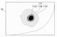
- a display mode (see display frame 5D in FIG. 6) in which the distribution of the fluorescence intensity within the range of the heat invasion region is displayed using the heat invasion degree distribution information is realized. I have.
- the distribution of the fluorescence intensity is classified into a plurality of regions (reference numerals 110A, 110B, and 110C in FIG. 6) within the range of the cauterization region (heat invasion region) 110 due to the heat invasion, and the form is different.
- regions reference numerals 110A, 110B, and 110C in FIG. 6
- the form is different.
- This makes it possible to display the distribution of the fluorescence intensity on the surface of the subject within the range of the heat invasion region in a visible state.
- the relationship information indicating the correlation between the fluorescence intensity and the heat invasion depth is stored in the storage unit. 35.
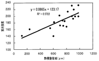
- FIG. 15 is a diagram showing a correlation between the fluorescence intensity and the heat invasion depth.
- the vertical axis indicates the fluorescence intensity.
- the fluorescence intensity indicates the luminance value (0 to 255) of the pixel of the acquired fluorescence image (no unit).
- the heat invasion depth calculation unit 34e calculates the relation information of the storage unit 35 and the heat invasion depth information of the heat invasion area included in the fluorescence image data obtained by the fluorescence observation.
- the heat invasion depth is calculated based on the above.
- the heat invasion depth result obtained in this manner according to the display form as shown in FIG. 7, that is, the distribution of the fluorescence intensity (110A, 110B, 110C) in the ablation region (heat invasion region) 110 due to heat invasion.
- the estimated depth is displayed (see display frame 5E in FIG. 7).
- FIG. 7 The display example shown in FIG. 7 indicates that the invasion depth is different depending on the fluorescence intensity distribution shown in FIG.
- reference numerals 110A, 110B, and 110C correspond to reference numerals 110A, 110B, and 110C, respectively, which indicate the distribution areas shown in FIG.
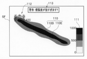
- FIGS. 8 and 9 are tables showing a case where the subject is cauterized by heat invasion using the endoscope system 1 of the present embodiment, and the subject including the cauterized region is observed in the fluorescence observation mode. 13 shows a third modification of the illustrated example.
- the depth of the heat invasion estimated from the result calculated using the heat invasion degree distribution information and the heat invasion depth information among the fluorescence intensity information included in the fluorescence image data is displayed. This is a display example.
- the target region is a cauterized region formed by heat invasion and formed in a substantially elongated shape on the surface of the subject.
- reference numerals 110D and 110E in FIG. 8 represent the thermal invasion degree distribution.
- the number displayed in the vicinity of the cautery region (heat invasion region) 110 indicates the specific information of the heat invasion depth calculated according to the distribution information. It is a display.
- a graph 111 representing the standard of the grayscale information representing the distribution of the fluorescence intensity is a predetermined area in the display area in the display frame 5F (in the example shown in FIG. 8, an area near the lower right edge toward the display frame 5F). It is configured to be displayed according to.
- the cautery region 110 formed by heat invasion and formed in a substantially circular shape on the surface of the subject is the target region.
- reference numerals 110F, 110G, and 110H in FIG. 9 represent the thermal invasion degree distribution.
- the display frame 5G of the monitor 5 in the vicinity of the cautery area (heat invasion area) 110, specific information of the heat invasion depth calculated according to the distribution information is displayed by a numeral.
- the points are the same as the display example of FIG.
- the graph 111 is the same as in FIG.
- the ablation range (distribution) and the invasion range (invasion depth) can be clearly displayed.
- an area to be cauterized (an area including a target lesion) is displayed on the monitor 5. This is performed while viewing the endoscope image.
- the white light observation and the fluorescence observation are simultaneously performed, the white light image data and the fluorescence image data are simultaneously acquired, and the fluorescence intensity information included in the fluorescence image data is obtained.
- predetermined image signal processing using (in particular, thermal invasion degree distribution information and thermal invasion depth information)
- a display image in a form in which the ablation range (distribution) and the invasion range (invasion depth) are clarified is obtained. Can be observed in real time.
- the surgeon such as a doctor can perform the procedure while constantly checking the degree of invasion of the target area.
- the energy device is unintentionally thermally invaded into a normal region other than the target region. Such accidents can be suppressed.
- the heat invasion depth calculation unit 34e calculates the heat invasion depth as described above.
- a notification unit 36 that notifies the user of the notification information is provided.
- the notification unit 36 outputs the generated notification information to the monitor 5 as described above, and provides a visual notification on the display screen of the monitor 5 (display unit). Display as information. Examples of the display include, for example, an indicator such as reference numeral 112 shown in FIG. 8, a warning display (display of character information, pictograms, and the like) indicated by reference numeral 113 in FIG. A warning icon or the like stored in the unit 35 or the like may be appropriately read and displayed.
- the display is designed to more easily draw the operator's attention by displaying the character color in red or the like, or performing blinking display. Can be considered.
- a sound generation device such as a speaker that outputs the notification information as sound information may be applied.
- white light observation and fluorescence observation can be performed simultaneously to obtain white light image data and fluorescence image data simultaneously.
- differential data is obtained by performing predetermined image processing based on the fluorescence image data before and after the treatment. It can be said that this difference data is data that accurately represents the difference in the intensity of the autofluorescence before and after the heat invasive treatment by the energy device in a form from which noise has been removed.
- the fluorescence image data of the “burn site” and “ Means for obtaining difference data from the fluorescence image data of the “part to be burned and not to be burned (not burnt)” may be considered.
- the monitor 5 can clearly and accurately display only the autofluorescent region generated by heat invasion. Will be able to
- the range (distribution and depth) of the cautery region of the living tissue caused by the thermal invasion using the energy device is determined by the biological tissue. It can be easily visualized by detecting the autofluorescence of the tissue.
- various image signal processing is performed by focusing on the fact that there is a correlation between the depth of heat invasion and the intensity of fluorescence, so that operators (users and users) such as doctors can perform heat invasion in real time.
- the range of the ablation region can be confirmed. Therefore, by using the endoscope system 1 of the present embodiment, it is possible to easily perform a reliable and highly accurate minimally invasive operation.
- the range in the depth direction (surface distribution) in addition to the range (surface distribution) on the surface of the living tissue of the subject, the range in the depth direction (surface distribution) (Depth distribution).
- the present invention is not limited to the above-described embodiment, and it is needless to say that various modifications and applications can be made without departing from the gist of the invention.
- the above embodiments include inventions at various stages, and various inventions can be extracted by appropriately combining a plurality of disclosed constituent elements. For example, even if some components are deleted from all the components shown in the one embodiment, if the problem to be solved by the invention can be solved and the effect of the invention can be obtained, this configuration is deleted. The configuration can be extracted as an invention. Further, components of different embodiments may be appropriately combined. The invention is not limited by the specific embodiments thereof except as limited by the appended claims.
Landscapes
- Health & Medical Sciences (AREA)
- Life Sciences & Earth Sciences (AREA)
- Surgery (AREA)
- Engineering & Computer Science (AREA)
- Medical Informatics (AREA)
- General Health & Medical Sciences (AREA)
- Nuclear Medicine, Radiotherapy & Molecular Imaging (AREA)
- Veterinary Medicine (AREA)
- Physics & Mathematics (AREA)
- Public Health (AREA)
- Biomedical Technology (AREA)
- Heart & Thoracic Surgery (AREA)
- Animal Behavior & Ethology (AREA)
- Molecular Biology (AREA)
- Biophysics (AREA)
- Optics & Photonics (AREA)
- Pathology (AREA)
- Radiology & Medical Imaging (AREA)
- Signal Processing (AREA)
- Neurology (AREA)
- Plasma & Fusion (AREA)
- Neurosurgery (AREA)
- Otolaryngology (AREA)
- Endoscopes (AREA)
- Surgical Instruments (AREA)
Abstract
Afin d'obtenir un dispositif d'observation d'agression thermique en mesure de rendre visible l'état cautérisé d'un spécimen tel qu'un tissu vivant, à l'aide d'un dispositif d'énergie, etc., la présente invention comprend : une source lumineuse 3 pour générer une lumière d'excitation destinée à irradier un spécimen ; une unité de génération d'image fluorescente 34a destinée à générer des données d'image fluorescente sur la base d'un signal d'imagerie obtenu par la réception de la lumière d'excitation et à représenter en image la lumière fluorescente générée à partir d'une région d'agression thermique du spécimen ; et une unité d'affichage 5 qui affiche une image et des informations sur la base de données d'image comprenant des données d'image fluorescente.
Priority Applications (7)
| Application Number | Priority Date | Filing Date | Title |
|---|---|---|---|
| CN201980055360.2A CN112601484B (zh) | 2018-09-10 | 2019-09-10 | 热侵袭观察装置、内窥镜系统、热侵袭观察系统、热侵袭观察方法 |
| CN202411481038.5A CN119344643A (zh) | 2018-09-10 | 2019-09-10 | 内窥镜系统、内窥镜系统的控制方法以及视频处理器 |
| DE112019004511.3T DE112019004511T5 (de) | 2018-09-10 | 2019-09-10 | Wärmeeindring-Beobachtungsvorrichtung, Endoskopsystem, Wärmeeindring-Beobachtungssystem und Wärmeeindring-Beobachtungsverfahren |
| JP2020546038A JP7000590B2 (ja) | 2018-09-10 | 2019-09-10 | 熱侵襲観察装置,内視鏡システム,熱侵襲観察システム,熱侵襲観察装置の作動方法 |
| US17/197,949 US12329361B2 (en) | 2018-09-10 | 2021-03-10 | Heat invasion observation apparatus, endoscope system, heat invasion observation system, and heat invasion observation method |
| JP2021209821A JP7350834B2 (ja) | 2018-09-10 | 2021-12-23 | 画像処理装置,内視鏡システム,画像処理装置の制御方法 |
| US19/216,297 US20250281033A1 (en) | 2018-09-10 | 2025-05-22 | Heat invasion observation apparatus, endoscope system, heat invasion observation system, and heat invasion observation method |
Applications Claiming Priority (2)
| Application Number | Priority Date | Filing Date | Title |
|---|---|---|---|
| PCT/JP2018/033457 WO2020053933A1 (fr) | 2018-09-10 | 2018-09-10 | Dispositif d'observation de lésion thermique et méthode d'observation de lésion thermique |
| JPPCT/JP2018/033457 | 2018-09-10 |
Related Child Applications (1)
| Application Number | Title | Priority Date | Filing Date |
|---|---|---|---|
| US17/197,949 Continuation US12329361B2 (en) | 2018-09-10 | 2021-03-10 | Heat invasion observation apparatus, endoscope system, heat invasion observation system, and heat invasion observation method |
Publications (1)
| Publication Number | Publication Date |
|---|---|
| WO2020054723A1 true WO2020054723A1 (fr) | 2020-03-19 |
Family
ID=69777754
Family Applications (2)
| Application Number | Title | Priority Date | Filing Date |
|---|---|---|---|
| PCT/JP2018/033457 Ceased WO2020053933A1 (fr) | 2018-09-10 | 2018-09-10 | Dispositif d'observation de lésion thermique et méthode d'observation de lésion thermique |
| PCT/JP2019/035563 Ceased WO2020054723A1 (fr) | 2018-09-10 | 2019-09-10 | Dispositif d'observation d'agression thermique, système d'endoscope, système d'observation d'agression thermique et procédé d'observation d'agression thermique |
Family Applications Before (1)
| Application Number | Title | Priority Date | Filing Date |
|---|---|---|---|
| PCT/JP2018/033457 Ceased WO2020053933A1 (fr) | 2018-09-10 | 2018-09-10 | Dispositif d'observation de lésion thermique et méthode d'observation de lésion thermique |
Country Status (5)
| Country | Link |
|---|---|
| US (2) | US12329361B2 (fr) |
| JP (2) | JP7000590B2 (fr) |
| CN (2) | CN119344643A (fr) |
| DE (1) | DE112019004511T5 (fr) |
| WO (2) | WO2020053933A1 (fr) |
Cited By (11)
| Publication number | Priority date | Publication date | Assignee | Title |
|---|---|---|---|---|
| CN113274122A (zh) * | 2021-07-02 | 2021-08-20 | 四川大学华西医院 | 一种家兔热损伤造模装置 |
| WO2022036400A1 (fr) * | 2020-08-21 | 2022-02-24 | Optiscan Pty Ltd | Sonde optique et système de traitement |
| WO2022070275A1 (fr) * | 2020-09-29 | 2022-04-07 | オリンパス株式会社 | Dispositif de support, système endoscopique, procédé de support et programme |
| WO2024166326A1 (fr) * | 2023-02-09 | 2024-08-15 | オリンパスメディカルシステムズ株式会社 | Appareil médical, système médical, procédé pour faire fonctionner un appareil médical et programme pour faire fonctionner un appareil médical |
| WO2024166312A1 (fr) * | 2023-02-09 | 2024-08-15 | オリンパスメディカルシステムズ株式会社 | Dispositif médical, système d'endoscope, procédé de commande, et programme de commande |
| WO2024166306A1 (fr) * | 2023-02-09 | 2024-08-15 | オリンパスメディカルシステムズ株式会社 | Dispositif médical, système d'endoscope, procédé de commande, programme de commande et dispositif d'apprentissage |
| WO2024166304A1 (fr) * | 2023-02-09 | 2024-08-15 | オリンパスメディカルシステムズ株式会社 | Dispositif de traitement d'image, système médical, procédé d'utilisation de dispositif de traitement d'image, et dispositif d'apprentissage |
| WO2024166330A1 (fr) * | 2023-02-09 | 2024-08-15 | オリンパスメディカルシステムズ株式会社 | Dispositif médical, système médical, procédé de fonctionnement de dispositif médical et programme |
| WO2024166311A1 (fr) * | 2023-02-09 | 2024-08-15 | オリンパスメディカルシステムズ株式会社 | Dispositif de traitement d'image, système médical, procédé de fonctionnement de dispositif de traitement d'image et dispositif d'apprentissage |
| US12226082B2 (en) | 2019-02-28 | 2025-02-18 | Olympus Corporation | Medical system, energy control method, and processor |
| WO2025234035A1 (fr) * | 2024-05-08 | 2025-11-13 | オリンパスメディカルシステムズ株式会社 | Dispositif médical, système d'endoscope, procédé de commande, et programme de commande |
Families Citing this family (5)
| Publication number | Priority date | Publication date | Assignee | Title |
|---|---|---|---|---|
| US12303187B2 (en) * | 2019-11-29 | 2025-05-20 | Canon Medical Systems Corporation | Medical image processing apparatus |
| US11998187B2 (en) * | 2021-09-10 | 2024-06-04 | Olympus Corporation | Suture method |
| CN120641020A (zh) * | 2023-02-09 | 2025-09-12 | 奥林巴斯医疗株式会社 | 医疗用装置、内窥镜系统、控制方法、控制程序以及学习装置 |
| CN120641028A (zh) * | 2023-02-09 | 2025-09-12 | 奥林巴斯医疗株式会社 | 医疗用装置、医疗系统、医疗用装置的工作方法以及医疗用装置的工作程序 |
| CN120641023A (zh) * | 2023-02-09 | 2025-09-12 | 奥林巴斯医疗株式会社 | 医疗用装置、医疗用系统、学习装置、医疗用装置的工作方法以及程序 |
Citations (4)
| Publication number | Priority date | Publication date | Assignee | Title |
|---|---|---|---|---|
| JP2000517053A (ja) * | 1996-08-30 | 2000-12-19 | アンスティチュ ナシオナル アグロノミック パリ―グリニョン | 乳などのタンパク質食品に実施される熱処理の評価方法 |
| WO2011040599A1 (fr) * | 2009-10-02 | 2011-04-07 | シャープ株式会社 | Dispositif destiné à la surveillance d'états de vaisseaux sanguins, et méthode de surveillance afférente |
| JP2016540558A (ja) * | 2013-11-14 | 2016-12-28 | ザ・ジョージ・ワシントン・ユニバーシティThe George Washingtonuniversity | 蛍光イメージングを用いて損傷の深さを決定するためのシステム及び方法 |
| JP2017023604A (ja) * | 2015-07-27 | 2017-02-02 | オリンパス株式会社 | 内視鏡システム |
Family Cites Families (26)
| Publication number | Priority date | Publication date | Assignee | Title |
|---|---|---|---|---|
| JPS61281432A (ja) * | 1985-06-06 | 1986-12-11 | Toshiba Corp | 蛍光ランプの製造方法 |
| GB9218185D0 (en) * | 1992-08-26 | 1992-10-14 | Ici Plc | Novel plants and processes for obtaining them |
| US5701902A (en) | 1994-09-14 | 1997-12-30 | Cedars-Sinai Medical Center | Spectroscopic burn injury evaluation apparatus and method |
| AU6232099A (en) * | 1999-09-30 | 2001-04-30 | Jipjap B.V. | Method and apparatus for determining autofluorescence of skin tissue |
| JP2001178672A (ja) * | 1999-12-24 | 2001-07-03 | Fuji Photo Film Co Ltd | 蛍光画像表示装置 |
| US6631289B2 (en) * | 2000-01-20 | 2003-10-07 | Research Foundation Of Cuny | System and method of fluorescence spectroscopic imaging for characterization and monitoring of tissue damage |
| WO2005032342A2 (fr) * | 2003-09-30 | 2005-04-14 | Vanderbilt University | Procedes et dispositifs de detection spectroscopique optique de la mort cellulaire et tissulaire |
| JP2007313169A (ja) * | 2006-05-29 | 2007-12-06 | Olympus Corp | 病変抽出装置および病変抽出方法 |
| JP5436757B2 (ja) | 2007-03-20 | 2014-03-05 | オリンパス株式会社 | 蛍光観察装置 |
| US20100179522A1 (en) * | 2009-01-14 | 2010-07-15 | Medsci Technologies, Inc. | System for endosurgical removal of tumors by laser ablation with treatment verification - particularly tumors of the prostate |
| JP5356191B2 (ja) * | 2009-11-26 | 2013-12-04 | オリンパス株式会社 | 蛍光観察装置 |
| JP2013523403A (ja) * | 2010-04-13 | 2013-06-17 | インターナショナル・ビジネス・マシーンズ・コーポレーション | レーザ・アブレーションにより組織を変化させるもしくは平滑化するまたはその両方を行うシステムおよび方法 |
| US9254090B2 (en) * | 2010-10-22 | 2016-02-09 | Intuitive Surgical Operations, Inc. | Tissue contrast imaging systems |
| JP5649947B2 (ja) | 2010-12-21 | 2015-01-07 | 富士フイルム株式会社 | 光計測システムおよび光計測システムの作動方法 |
| ES2727868T3 (es) * | 2011-09-22 | 2019-10-21 | Univ George Washington | Sistemas para visualizar el tejido ablacionado |
| US9907471B2 (en) * | 2013-10-08 | 2018-03-06 | The Board Of Trustees Of The Leland Stanford Junior University | Visualization of heart wall tissue |
| JP5861002B2 (ja) * | 2013-10-15 | 2016-02-16 | オリンパス株式会社 | 医療器具 |
| US20150141847A1 (en) * | 2013-11-20 | 2015-05-21 | The George Washington University | Systems and methods for hyperspectral analysis of cardiac tissue |
| US9757182B2 (en) * | 2014-06-02 | 2017-09-12 | Biosense Webster (Israel) Ltd. | Identification and visualization of gaps between cardiac ablation sites |
| AU2015353464B2 (en) * | 2014-11-25 | 2020-07-16 | 460Medical, Inc. | Visualization catheters |
| WO2016194568A1 (fr) * | 2015-05-29 | 2016-12-08 | オリンパス株式会社 | Dispositif médical et matériau de revêtement |
| JP2017051149A (ja) | 2015-09-10 | 2017-03-16 | アズビル株式会社 | 液中生物粒子の検出装置、及び液中生物粒子の検出方法 |
| WO2017094188A1 (fr) * | 2015-12-04 | 2017-06-08 | 株式会社日立製作所 | Dispositif d'inspection de glycation de la peau, système de dispositif d'inspection de glycation de la peau, et procédé d'inspection de glycation de la peau |
| JPWO2017221336A1 (ja) * | 2016-06-21 | 2019-04-11 | オリンパス株式会社 | 内視鏡システム、画像処理装置、画像処理方法およびプログラム |
| EP3678578A4 (fr) * | 2017-09-06 | 2021-06-16 | Technion Research & Development Foundation Limited | Système robotique de chirurgie minimalement invasive |
| JP2021513390A (ja) * | 2018-02-02 | 2021-05-27 | ユニバーシティー ヘルス ネットワーク | 腫瘍の視覚化および除去のためのデバイス、システム、および方法 |
-
2018
- 2018-09-10 WO PCT/JP2018/033457 patent/WO2020053933A1/fr not_active Ceased
-
2019
- 2019-09-10 DE DE112019004511.3T patent/DE112019004511T5/de active Pending
- 2019-09-10 CN CN202411481038.5A patent/CN119344643A/zh active Pending
- 2019-09-10 WO PCT/JP2019/035563 patent/WO2020054723A1/fr not_active Ceased
- 2019-09-10 CN CN201980055360.2A patent/CN112601484B/zh active Active
- 2019-09-10 JP JP2020546038A patent/JP7000590B2/ja active Active
-
2021
- 2021-03-10 US US17/197,949 patent/US12329361B2/en active Active
- 2021-12-23 JP JP2021209821A patent/JP7350834B2/ja active Active
-
2025
- 2025-05-22 US US19/216,297 patent/US20250281033A1/en active Pending
Patent Citations (4)
| Publication number | Priority date | Publication date | Assignee | Title |
|---|---|---|---|---|
| JP2000517053A (ja) * | 1996-08-30 | 2000-12-19 | アンスティチュ ナシオナル アグロノミック パリ―グリニョン | 乳などのタンパク質食品に実施される熱処理の評価方法 |
| WO2011040599A1 (fr) * | 2009-10-02 | 2011-04-07 | シャープ株式会社 | Dispositif destiné à la surveillance d'états de vaisseaux sanguins, et méthode de surveillance afférente |
| JP2016540558A (ja) * | 2013-11-14 | 2016-12-28 | ザ・ジョージ・ワシントン・ユニバーシティThe George Washingtonuniversity | 蛍光イメージングを用いて損傷の深さを決定するためのシステム及び方法 |
| JP2017023604A (ja) * | 2015-07-27 | 2017-02-02 | オリンパス株式会社 | 内視鏡システム |
Cited By (13)
| Publication number | Priority date | Publication date | Assignee | Title |
|---|---|---|---|---|
| US12226082B2 (en) | 2019-02-28 | 2025-02-18 | Olympus Corporation | Medical system, energy control method, and processor |
| WO2022036400A1 (fr) * | 2020-08-21 | 2022-02-24 | Optiscan Pty Ltd | Sonde optique et système de traitement |
| WO2022070275A1 (fr) * | 2020-09-29 | 2022-04-07 | オリンパス株式会社 | Dispositif de support, système endoscopique, procédé de support et programme |
| JPWO2022070275A1 (fr) * | 2020-09-29 | 2022-04-07 | ||
| CN116322468A (zh) * | 2020-09-29 | 2023-06-23 | 奥林巴斯株式会社 | 辅助装置、内窥镜系统、辅助方法以及程序 |
| CN113274122A (zh) * | 2021-07-02 | 2021-08-20 | 四川大学华西医院 | 一种家兔热损伤造模装置 |
| WO2024166312A1 (fr) * | 2023-02-09 | 2024-08-15 | オリンパスメディカルシステムズ株式会社 | Dispositif médical, système d'endoscope, procédé de commande, et programme de commande |
| WO2024166306A1 (fr) * | 2023-02-09 | 2024-08-15 | オリンパスメディカルシステムズ株式会社 | Dispositif médical, système d'endoscope, procédé de commande, programme de commande et dispositif d'apprentissage |
| WO2024166304A1 (fr) * | 2023-02-09 | 2024-08-15 | オリンパスメディカルシステムズ株式会社 | Dispositif de traitement d'image, système médical, procédé d'utilisation de dispositif de traitement d'image, et dispositif d'apprentissage |
| WO2024166330A1 (fr) * | 2023-02-09 | 2024-08-15 | オリンパスメディカルシステムズ株式会社 | Dispositif médical, système médical, procédé de fonctionnement de dispositif médical et programme |
| WO2024166311A1 (fr) * | 2023-02-09 | 2024-08-15 | オリンパスメディカルシステムズ株式会社 | Dispositif de traitement d'image, système médical, procédé de fonctionnement de dispositif de traitement d'image et dispositif d'apprentissage |
| WO2024166326A1 (fr) * | 2023-02-09 | 2024-08-15 | オリンパスメディカルシステムズ株式会社 | Appareil médical, système médical, procédé pour faire fonctionner un appareil médical et programme pour faire fonctionner un appareil médical |
| WO2025234035A1 (fr) * | 2024-05-08 | 2025-11-13 | オリンパスメディカルシステムズ株式会社 | Dispositif médical, système d'endoscope, procédé de commande, et programme de commande |
Also Published As
| Publication number | Publication date |
|---|---|
| JPWO2020054723A1 (ja) | 2021-08-30 |
| US20250281033A1 (en) | 2025-09-11 |
| JP7350834B2 (ja) | 2023-09-26 |
| DE112019004511T5 (de) | 2021-06-02 |
| CN119344643A (zh) | 2025-01-24 |
| CN112601484B (zh) | 2024-11-19 |
| WO2020053933A1 (fr) | 2020-03-19 |
| JP2022040170A (ja) | 2022-03-10 |
| US12329361B2 (en) | 2025-06-17 |
| JP7000590B2 (ja) | 2022-01-19 |
| US20210186594A1 (en) | 2021-06-24 |
| CN112601484A (zh) | 2021-04-02 |
Similar Documents
| Publication | Publication Date | Title |
|---|---|---|
| JP7350834B2 (ja) | 画像処理装置,内視鏡システム,画像処理装置の制御方法 | |
| US12171399B2 (en) | Surgical devices, systems, and methods using multi-source imaging | |
| US12023096B2 (en) | Medical laser apparatus and system | |
| JP4477230B2 (ja) | 光学生検装置および組織診断方法 | |
| JP7212756B2 (ja) | 医療用システム、エネルギー制御方法、およびプロセッサ | |
| JP2017513645A (ja) | アブレーション処置の際にicg色素組成物を用いて組織を視覚化するためのシステムおよび方法 | |
| US20100168584A1 (en) | Biological observation apparatus, biological observation method, and endoscopic apparatus | |
| JP7720721B2 (ja) | 内視鏡システム、医療画像処理装置及びその作動方法 | |
| US20150105769A1 (en) | Method for endoscopic treatment | |
| CN116322468A (zh) | 辅助装置、内窥镜系统、辅助方法以及程序 | |
| CN115381379A (zh) | 医疗图像处理装置、内窥镜系统及医疗图像处理装置的工作方法 | |
| US10537225B2 (en) | Marking method and resecting method | |
| JP7147890B2 (ja) | 情報処理システム、情報処理方法及びプログラム | |
| US20250359741A1 (en) | Medical device, medical system, medical device operation method, and computer-readable recording medium | |
| US20250359728A1 (en) | Control device, medical system, operation method of medical device, and computer-readable recording medium | |
| JP2024536172A (ja) | 多光源撮像を使用する外科用デバイス、システム、及び方法 | |
| WO2024166307A1 (fr) | Dispositif médical, système médical, procédé de fonctionnement de dispositif médical et programme de fonctionnement de dispositif médical | |
| EP4210623A1 (fr) | Dispositifs, systèmes et procédés chirurgicaux utilisant une imagerie multisource | |
| CN120641024A (zh) | 医疗用装置、医疗用系统、医疗用装置的工作方法以及程序 | |
| JP2005305182A (ja) | 光診断装置 |
Legal Events
| Date | Code | Title | Description |
|---|---|---|---|
| 121 | Ep: the epo has been informed by wipo that ep was designated in this application |
Ref document number: 19859248 Country of ref document: EP Kind code of ref document: A1 |
|
| ENP | Entry into the national phase |
Ref document number: 2020546038 Country of ref document: JP Kind code of ref document: A |
|
| 122 | Ep: pct application non-entry in european phase |
Ref document number: 19859248 Country of ref document: EP Kind code of ref document: A1 |