WO2020056717A1 - Procédé et dispositif d'association de ressources, terminal, et appareil de réseau - Google Patents
Procédé et dispositif d'association de ressources, terminal, et appareil de réseau Download PDFInfo
- Publication number
- WO2020056717A1 WO2020056717A1 PCT/CN2018/106911 CN2018106911W WO2020056717A1 WO 2020056717 A1 WO2020056717 A1 WO 2020056717A1 CN 2018106911 W CN2018106911 W CN 2018106911W WO 2020056717 A1 WO2020056717 A1 WO 2020056717A1
- Authority
- WO
- WIPO (PCT)
- Prior art keywords
- index information
- pusch
- target
- preamble
- resource
- Prior art date
- Legal status (The legal status is an assumption and is not a legal conclusion. Google has not performed a legal analysis and makes no representation as to the accuracy of the status listed.)
- Ceased
Links
Images




Classifications
-
- H—ELECTRICITY
- H04—ELECTRIC COMMUNICATION TECHNIQUE
- H04W—WIRELESS COMMUNICATION NETWORKS
- H04W74/00—Wireless channel access
- H04W74/08—Non-scheduled access, e.g. ALOHA
Definitions
- Embodiments of the present application relate to the field of mobile communication technologies, and in particular, to a method and device for resource association, a terminal, and a network device.
- a user equipment accesses a network and acquires a radio resource control (RRC, Radio Resource Control) connection, it first needs to perform a random access process.
- the current random access process uses a four-step random access process (referred to as 4 step RACH).
- 4 step RACH a four-step random access process
- 2 step RACH a two-step random access process
- MSG1 and MSG3 are sent at the same time or almost at the same time. How to associate the MSG1 and MSG3 of a UE in the two-step RACH is a problem to be solved.
- the embodiments of the present application provide a resource association method and device, a terminal, and a network device.
- the terminal acquires first configuration information, where the first configuration information includes a set of preambles and a set of configuration information of a physical uplink shared channel PUSCH resource;
- a target physical random access channel (PRACH) resource Determining, by the terminal, a target physical random access channel (PRACH) resource, and selecting a preamble from the set of preambles as a target preamble to transmit on the target PRACH resource;
- PRACH physical random access channel
- the terminal transmits MSG3 on the target PUSCH resource.
- the network device sends first configuration information, where the first configuration information includes a set of preambles and a set of configuration information of PUSCH resources;
- the network device detects a preamble on a PRACH resource and detects MSG3 on a PUSCH resource, and determines a preamble and MSG3 belonging to a terminal according to a correspondence between the preamble and the PUSCH resource.
- An obtaining unit configured to obtain first configuration information, where the first configuration information includes a set of preambles and a set of configuration information of PUSCH resources;
- a first sending unit configured to determine a PRACH resource, and select a preamble from the set of preambles as a target preamble to transmit on the target PRACH resource;
- a determining unit configured to determine second index information of a target PUSCH resource based on the first index information of the target preamble, and determine the target PUSCH in the group of PUSCH resources based on the second index information of the target PUSCH resource Resources
- a second sending unit is configured to transmit MSG3 on the target PUSCH resource.
- a sending unit configured to send first configuration information, where the first configuration information includes a set of preambles and a set of configuration information of PUSCH resources;
- a first receiving unit configured to detect a preamble on a PRACH resource
- a second receiving unit configured to detect MSG3 on a PUSCH resource
- a determining unit configured to determine a preamble and MSG3 belonging to a terminal according to a correspondence between the preamble and the PUSCH resource.
- the terminal provided in the embodiment of the present application includes a processor and a memory.
- the memory is used to store a computer program
- the processor is used to call and run the computer program stored in the memory to execute the above-mentioned resource association method.
- the network device provided in the embodiment of the present application includes a processor and a memory.
- the memory is used to store a computer program
- the processor is used to call and run the computer program stored in the memory to execute the above-mentioned resource association method.
- the chip provided in the embodiment of the present application is used to implement the foregoing resource association method.
- the chip includes: a processor, configured to call and run a computer program from the memory, so that a device installed with the chip executes the foregoing resource association method.
- the computer-readable storage medium provided in the embodiment of the present application is used to store a computer program, and the computer program causes a computer to execute the foregoing resource association method.
- the computer program product provided in the embodiment of the present application includes computer program instructions, and the computer program instructions cause a computer to execute the foregoing resource association method.
- the computer program provided in the embodiment of the present application when run on a computer, causes the computer to execute the above-mentioned resource association method.
- the network side configures a set of preambles and a set of PUSCH resources, where the PUSCH resources are used to transmit MSG3.
- the UE associates the preamble of MSG1 with the PUSCH resource that transmits MSG3, so that the network
- the side can correctly pair MSG1 and MSG3 of a UE, so as to correctly send a random access response to the UE.
- FIG. 1 is a schematic diagram of a communication system architecture according to an embodiment of the present application.
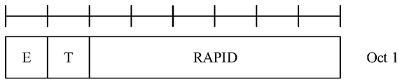
- Figure 3 (a) is the format of E / T / R / R / BI MAC subheader
- Figure 3 (b) is the format of E / T / RAPID MAC subheader
- Figure 3 (c) is the format of MAC PDUs (including MAC RARs);
- Figure 3 (d) is a schematic diagram of a MAC RAR
- FIG. 4 is a first schematic flowchart of a resource association method according to an embodiment of the present application.
- FIG. 5 is a schematic diagram of resource configuration according to an embodiment of the present application.
- FIG. 6 is a second schematic flowchart of a resource association method according to an embodiment of the present application.
- FIG. 7 is a first schematic structural composition diagram of a resource association device according to an embodiment of the present application.
- FIG. 8 is a second schematic diagram of the structure and composition of a resource association device according to an embodiment of the present application.
- FIG. 9 is a schematic structural diagram of a communication device according to an embodiment of the present application.
- FIG. 10 is a schematic structural diagram of a chip according to an embodiment of the present application.
- FIG. 11 is a schematic block diagram of a communication system according to an embodiment of the present application.
- GSM Global System for Mobile
- CDMA Code Division Multiple Access
- Wideband Code Division Multiple Access Wideband Code Division Multiple Access
- GPRS General Packet Radio Service
- LTE Long Term Evolution
- FDD Frequency Division Duplex
- TDD Time Division Duplex
- UMTS Universal Mobile Telecommunication System
- WiMAX Worldwide Interoperability for Microwave Access
- the communication system 100 may include a network device 110, and the network device 110 may be a device that communicates with the terminal 120 (or a communication terminal or terminal).
- the network device 110 may provide communication coverage for a specific geographic area, and may communicate with terminals located within the coverage area.
- the network device 110 may be a base station (Base Transceiver Station, BTS) in a GSM system or a CDMA system, or a base station (NodeB, NB) in a WCDMA system, or an evolved base station in an LTE system.
- BTS Base Transceiver Station
- NodeB NodeB
- the network device may be a mobile switching center, relay station, access point, vehicle equipment, Wearable devices, hubs, switches, bridges, routers, network-side devices in 5G networks, or network devices in public land mobile networks (PLMN) that will evolve in the future.
- PLMN public land mobile networks
- the communication system 100 further includes at least one terminal 120 located within a coverage area of the network device 110.
- terminal used herein includes, but is not limited to, connection via a wired line, such as via a Public Switched Telephone Network (PSTN), Digital Subscriber Line (DSL), digital cable, direct cable connection; And / or another data connection / network; and / or via a wireless interface, such as for cellular networks, wireless local area networks (WLAN), digital television networks such as DVB-H networks, satellite networks, AM-FM A broadcast transmitter; and / or another terminal device configured to receive / transmit communication signals; and / or an Internet of Things (IoT) device.
- PSTN Public Switched Telephone Network
- DSL Digital Subscriber Line
- WLAN wireless local area networks
- DVB-H networks digital television networks
- satellite networks satellite networks
- AM-FM A broadcast transmitter AM-FM A broadcast transmitter
- IoT Internet of Things
- a terminal configured to communicate through a wireless interface may be referred to as a "wireless communication terminal", a “wireless terminal”, or a “mobile terminal”.
- mobile terminals include, but are not limited to, satellite or cellular phones; personal communications systems (PCS) terminals that can combine cellular radiotelephones with data processing, facsimile, and data communications capabilities; can include radiotelephones, pagers, Internet / internal PDA with network access, web browser, notepad, calendar, and / or Global Positioning System (GPS) receiver; and conventional laptop and / or palm-type receivers or others including radiotelephone transceivers Electronic device.
- PCS personal communications systems
- GPS Global Positioning System
- a terminal may refer to an access terminal, user equipment (UE), user unit, user station, mobile station, mobile station, remote station, remote terminal, mobile device, user terminal, terminal, wireless communication device, user agent, or user Device.
- the access terminal can be a cellular phone, a cordless phone, a Session Initiation Protocol (SIP) phone, a Wireless Local Loop (WLL) station, a Personal Digital Processing (PDA), and wireless communication.
- the terminals 120 may perform terminal direct connection (Device to Device, D2D) communication.
- D2D Terminal to Device
- the 5G system or the 5G network may also be referred to as a New Radio (NR) system or an NR network.
- NR New Radio
- FIG. 1 exemplarily shows one network device and two terminals.
- the communication system 100 may include multiple network devices and each network device may include other numbers of terminals within its coverage area. Embodiments of the present application This is not limited.
- the communication system 100 may further include other network entities such as a network controller, a mobility management entity, and the like in this embodiment of the present application is not limited thereto.
- network entities such as a network controller, a mobility management entity, and the like in this embodiment of the present application is not limited thereto.
- a communication device may include a network device 110 and a terminal 120 having a communication function, and the network device 110 and the terminal 120 may be specific devices described above, and are not described herein again; communication
- the device may also include other devices in the communication system 100, such as other network entities such as a network controller and a mobile management entity, which are not limited in the embodiments of the present application.
- NR New Radio
- LTE Long Term Evolution
- NR New Radio
- LTE Long Term Evolution
- NR New Radio
- LTE Long Term Evolution
- NR New Radio
- the technical solution of the embodiment of the present invention is mainly applied to a 5G mobile communication system.
- the technical solution of the embodiment of the present invention is not limited to the 5G mobile communication system, and can also be applied to other types of mobile communication systems.
- eMBB targets users to obtain multimedia content, services, and data, and its business demand is growing rapidly. Because eMBB may be deployed in different scenarios, such as indoor, urban, rural, etc., and its service capabilities and requirements vary widely, it is necessary to analyze services in conjunction with specific deployment scenarios.
- URLLC scenario Typical applications of URLLC include: industrial automation, electric power automation, telemedicine operations, and traffic safety assurance.
- mMTC scenario The typical characteristics of URLLC include: high connection density, small amount of data, delay-insensitive services, low cost of modules, and long service life.
- FIG. 2 is a flowchart of a four-step random access process, including the following steps:
- the UE sends MSG1 to the gNB: Random Access Preamble.
- the UE selects a PRACH resource, and sends the selected preamble on the PRACH resource.
- a PRACH resource there are a total of 64 Preambles, and each Preamble corresponds to an index, and the value of the index ranges from 0 to 63.
- the gNB sends MSG2: Random Access Response (RAR, Random Access Response) to the UE.
- RAR Random Access Response
- the gNB responds to MSG1 to send a random access response to the UE, and the UE calculates a random access-radio network temporary identity (RA-RNTI) for scrambling scheduling information of the MSG2 according to the PRACH resource that sent the Preamble.
- the data format of the media access control (MAC) layer of the RAR is shown in FIG. 3 (a), FIG. 3 (b), FIG. 3 (c), and FIG. 3 (d).
- FIG. 3 (a) It is the format of E / T / R / R / / BI MAC subheader.
- Figure 3 (b) is the format of E / T / RAPID MAC subheader.
- Figure 3 (c) is the format of MAC PDU (including MAC RARs).
- Figure 3 ( d) is a schematic diagram of MAC RAR.
- UE sends MSG3 to gNB: Scheduled Transmission
- the network side allocates uplink resources for sending MSG3 to the UE, and the UE sends MSG3 on the uplink resources (UL grant) allocated by the network side.
- gNB sends MSG4 to UE: Contention Resolution
- MSG1 and MSG3 are sent simultaneously or almost simultaneously (MSG3 can be sent without waiting for MSG2 here), and MSG2 and MSG4 are sent together (one PDSCH transmission or two PDSCH transmissions).
- association between MSG1 and MSG3 of a UE is implemented in 2step RACH.
- FIG. 4 is a schematic flowchart of a resource association method according to an embodiment of the present application. As shown in FIG. 4, the resource association method includes the following steps:
- Step 401 The terminal obtains first configuration information, where the first configuration information includes a set of preambles and a set of configuration information of PUSCH resources.
- the terminal may be any device capable of communicating with a network, such as a mobile phone, a tablet computer, a notebook, and a vehicle-mounted terminal.
- the terminal receives the first configuration information sent by a network device.
- the network device may be a base station, for example, a gNB in 5G, or an eNB in 4G.
- the terminal receives the first configuration information sent by the network device through a system broadcast message.
- the network side configures 2 steps RACH resources for the terminal, including a set of preambles for 2 step RACH, and a set of PUSCH resources for transmitting MSG3 in 2 step RACH.
- the network side is configured with four Preambles, namely Preamble0, Preamble1, Preamble2, and Preamble3.
- the network side is also configured with four PUSCH resources, namely PUSCH1, PUSCH2, PUSCH3, and PUSCH4. , These 4 PUSCH resources are associated with 1 PRACH resource.
- FIG. 5 takes a group of PUSCH resources including 4 PUSCH resources as an example, and is not limited to this.
- a group of PUSCH resources includes n PUSCH resources, and the size of n depends on the capability of the network side.
- the number of preambles included in the set of preambles is the same as the number of PUSCH resources included in the set of PUSCH resources. Referring to FIG. 5, there are four preambles configured on the network side, and four PUSCH resources are configured.
- Step 402 The terminal determines a target PRACH resource, and selects a preamble from the set of preambles as a target preamble to transmit on the target PRACH resource.
- the target PRACH resource may be determined in the following manner: the terminal receives a group of synchronization signal blocks (SSB, PSS / SSS and PBCH Block), and determines its corresponding reference signal received power (RSRP, Reference SignalReceiving Power) Measured values, select an appropriate SSB according to the threshold, and then determine the PRACH time-frequency resource based on the association between the SSB and the PRACH.
- SSB group of synchronization signal blocks
- RSRP Reference SignalReceiving Power
- Step 403 The terminal determines the second index information of the target PUSCH resource based on the first index information of the target preamble, and determines the target in the group of PUSCH resources based on the second index information of the target PUSCH resource. PUSCH resources.
- the index information of each preamble in the set of preambles has a corresponding relationship with the index information of each PUSCH resource in the set of PUSCH resources. Further, the index information of different preambles corresponds to index information of different PUSCH resources.
- preambles are configured on the network side, which are Preamble0, Preamble1, Preamble2, Preamble3, and 4 PUSCH resources are configured on the network side, respectively PUSCH1, PUSCH2, PUSCH3, and PUSCH4, where Preamble0 corresponds to PUSCH4 Preamble1 corresponds to PUSCH3, Preamble2 corresponds to PUSCH2, and Preamble3 corresponds to PUSCH1.
- the correspondence between the index information of the preamble and the index information of the PUSCH resource is not limited to this, and the correspondence between the index information of the preamble and the index information of the PUSCH resource may also be represented by a functional relationship.
- index2 indicates the second index information of the target PUSCH resource
- index1 indicates the first index information of the target preamble
- n indicates the number of PUSCH resources included in the group of PUSCH resources
- mod indicates a remainder operation.
- index2 index1 mod n
- the index2 corresponding to different values of n needs to be different, so that the network side can correctly pair MSG1 and MSG3 sent by a UE.
- Step 404 The terminal transmits MSG3 on the target PUSCH resource.
- the RAR that is, MSG2 is correctly sent to the UE, and then the UE calculates a random access-wireless network temporary identity (RA) -RNTI (Random Access-Radio Network Tempory Identity), uses RA-RNTI to descramble the physical downlink control channel (PDCCH, Physical Downlink Control Channel) that schedules MSG2 to obtain MSG2.
- RA random access-wireless network temporary identity
- FIG. 6 is a second flowchart of a resource association method according to an embodiment of the present application. As shown in FIG. 6, the resource association method includes the following steps:
- Step 601 The network device sends first configuration information, where the first configuration information includes a set of preambles and a set of configuration information of PUSCH resources.
- the network device may be a base station, for example, a gNB in 5G, or an eNB in 4G.
- the network device sends the first configuration information through a system broadcast message.
- the network side configures 2 steps RACH resources for the terminal, including a set of preambles for 2 step RACH, and a set of PUSCH resources for transmitting MSG3 in 2 step RACH.
- the network side is configured with four Preambles, namely Preamble0, Preamble1, Preamble2, and Preamble3.
- the network side is also configured with four PUSCH resources, namely PUSCH1, PUSCH2, PUSCH3, and PUSCH4, , These 4 PUSCH resources are associated with 1 PRACH resource.
- FIG. 5 takes a group of PUSCH resources including 4 PUSCH resources as an example, and is not limited to this.
- a group of PUSCH resources includes n PUSCH resources, and the size of n depends on the capability of the network side.
- the number of preambles included in the set of preambles is the same as the number of PUSCH resources included in the set of PUSCH resources. Referring to FIG. 5, there are four preambles configured on the network side, and four PUSCH resources are configured.
- Step 602 The network device detects a preamble on a PRACH resource and detects MSG3 on a PUSCH resource, and determines a preamble and MSG3 belonging to a terminal according to a correspondence between the preamble and the PUSCH resource.
- the terminal determines a target PRACH resource, and selects a preamble from the set of preambles as a target preamble to transmit on the target PRACH resource.
- the terminal determines second index information of a target PUSCH resource based on the first index information of the target preamble, and determines the target PUSCH resource in the group of PUSCH resources based on the second index information of the target PUSCH resource.
- the terminal transmits MSG3 on the target PUSCH resource.
- the index information of each preamble in the set of preambles has a corresponding relationship with the index information of each PUSCH resource in the set of PUSCH resources. Further, the index information of different preambles corresponds to index information of different PUSCH resources.
- preambles are configured on the network side, which are Preamble0, Preamble1, Preamble2, Preamble3, and 4 PUSCH resources are configured on the network side, which are PUSCH1, PUSCH2, PUSCH3, and PUSCH4, where Preamble0 corresponds to PUSCH4.
- Preamble1 corresponds to PUSCH3,
- Preamble2 corresponds to PUSCH2,
- Preamble3 corresponds to PUSCH1.
- the correspondence between the index information of the preamble and the index information of the PUSCH resource is not limited to this, and the correspondence between the index information of the preamble and the index information of the PUSCH resource may also be represented by a functional relationship.
- index2 indicates the second index information of the target PUSCH resource transmitting MSG3
- index1 indicates the first index information of the target preamble
- n indicates the number of PUSCH resources included in the set of PUSCH resources
- mod indicates the remainder operation.
- index2 index1 mod n
- the index2 corresponding to different values of n needs to be different, so that the network side can correctly pair MSG1 and MSG3 sent by a UE.
- the network side after the network side correctly pairs MSG1 and MSG3 sent by a UE, it correctly sends a RAR, that is, MSG2, to the UE. Then, the UE calculates the RA-RNTI according to the selected PRACH resource, and uses RA-RNTI to schedule The PDCCH of MSG2 is descrambled to obtain MSG2.
- FIG. 7 is a first schematic diagram of the structure and composition of a resource association device according to an embodiment of the present application. As shown in FIG. 7, the device includes:
- An obtaining unit 701 configured to obtain first configuration information, where the first configuration information includes a set of preambles and a set of configuration information of PUSCH resources;
- a first sending unit 702 configured to determine a PRACH resource, and select a preamble from the set of preambles as a target preamble to transmit on the target PRACH resource;
- a determining unit 703, configured to determine second index information of a target PUSCH resource based on the first index information of the target preamble, and determine the target in the group of PUSCH resources based on the second index information of the target PUSCH resource PUSCH resources;
- the second sending unit 704 is configured to transmit MSG3 on the target PUSCH resource.
- the number of preambles included in the set of preambles is the same as the number of PUSCH resources included in the set of PUSCH resources.
- the index information of each preamble in the set of preambles has a corresponding relationship with the index information of each PUSCH resource in the set of PUSCH resources.
- the index information of different preambles corresponds to index information of different PUSCH resources.
- index2 indicates the second index information of the target PUSCH resource
- index1 indicates the first index information of the target preamble
- n indicates the number of PUSCH resources included in the group of PUSCH resources
- mod indicates a remainder operation.
- FIG. 8 is a second schematic diagram of the structure and composition of a resource association device according to an embodiment of the present application. As shown in FIG. 8, the device includes:
- the sending unit 801 is configured to send first configuration information, where the first configuration information includes a set of preambles and a set of configuration information of PUSCH resources;
- a first receiving unit 802 configured to detect a preamble on a PRACH resource
- a second receiving unit 803, configured to detect MSG3 on a PUSCH resource
- a determining unit 804 is configured to determine a preamble and MSG3 belonging to a terminal according to a correspondence between the preamble and the PUSCH resource.
- the number of preambles included in the set of preambles is the same as the number of PUSCH resources included in the set of PUSCH resources.
- the index information of each preamble in the set of preambles has a corresponding relationship with the index information of each PUSCH resource in the set of PUSCH resources.
- the index information of different preambles corresponds to index information of different PUSCH resources.
- index2 indicates the second index information of the target PUSCH resource transmitting MSG3
- index1 indicates the first index information of the target preamble
- n indicates the number of PUSCH resources included in the set of PUSCH resources
- mod indicates the remainder operation.
- FIG. 9 is a schematic structural diagram of a communication device 600 according to an embodiment of the present application.
- the communication device may be a terminal or a network device.
- the communication device 600 shown in FIG. 9 includes a processor 610, and the processor 610 may call and run a computer program from a memory to implement the method in the embodiment of the present application.
- the communication device 600 may further include a memory 620.
- the processor 610 may call and run a computer program from the memory 620 to implement the method in the embodiment of the present application.
- the memory 620 may be a separate device independent of the processor 610, or may be integrated in the processor 610.
- the communication device 600 may further include a transceiver 630, and the processor 610 may control the transceiver 630 to communicate with other devices, and specifically, may send information or data to other devices, or receive other Information or data sent by the device.
- the transceiver 630 may include a transmitter and a receiver.
- the transceiver 630 may further include antennas, and the number of antennas may be one or more.
- the communication device 600 may specifically be a network device according to the embodiment of the present application, and the communication device 600 may implement a corresponding process implemented by the network device in each method of the embodiment of the present application. For brevity, details are not described herein again. .
- the communication device 600 may specifically be a mobile terminal / terminal of the embodiment of the present application, and the communication device 600 may implement the corresponding process implemented by the mobile terminal / terminal in each method of the embodiment of the present application. For simplicity, in This will not be repeated here.
- FIG. 10 is a schematic structural diagram of a chip according to an embodiment of the present application.
- the chip 700 shown in FIG. 10 includes a processor 710, and the processor 710 can call and run a computer program from a memory to implement the method in the embodiment of the present application.
- the chip 700 may further include a memory 720.
- the processor 710 may call and run a computer program from the memory 720 to implement the method in the embodiment of the present application.
- the memory 720 may be a separate device independent of the processor 710, or may be integrated in the processor 710.
- the chip 700 may further include an input interface 730.
- the processor 710 may control the input interface 730 to communicate with other devices or chips. Specifically, the processor 710 may obtain information or data sent by the other devices or chips.
- the chip 700 may further include an output interface 740.
- the processor 710 may control the output interface 740 to communicate with other devices or chips. Specifically, the processor 710 may output information or data to the other devices or chips.
- the chip may be applied to the network device in the embodiment of the present application, and the chip may implement the corresponding process implemented by the network device in each method of the embodiment of the present application.
- the chip may be applied to the network device in the embodiment of the present application, and the chip may implement the corresponding process implemented by the network device in each method of the embodiment of the present application.
- the chip can be applied to the mobile terminal / terminal in the embodiments of the present application, and the chip can implement the corresponding process implemented by the mobile terminal / terminal in each method of the embodiments of the present application. To repeat.
- the chip mentioned in the embodiments of the present application may also be referred to as a system-level chip, a system chip, a chip system or a system-on-chip.
- FIG. 11 is a schematic block diagram of a communication system 900 according to an embodiment of the present application. As shown in FIG. 11, the communication system 900 includes a terminal 910 and a network device 920.
- the terminal 910 may be used to implement the corresponding functions implemented by the terminal in the foregoing method
- the network device 920 may be used to implement the corresponding functions implemented by the network device in the foregoing method.
- details are not described herein again.
- the processor in the embodiment of the present application may be an integrated circuit chip and has a signal processing capability.
- each step of the foregoing method embodiment may be completed by using an integrated logic circuit of hardware in a processor or an instruction in a form of software.
- the above processor may be a general-purpose processor, a digital signal processor (DSP), an application specific integrated circuit (ASIC), an off-the-shelf programmable gate array (Field, Programmable Gate Array, FPGA), or other Programming logic devices, discrete gate or transistor logic devices, discrete hardware components.
- DSP digital signal processor
- ASIC application specific integrated circuit
- FPGA off-the-shelf programmable gate array
- Various methods, steps, and logical block diagrams disclosed in the embodiments of the present application can be implemented or executed.
- a general-purpose processor may be a microprocessor or the processor may be any conventional processor or the like.
- the steps of the method disclosed in combination with the embodiments of the present application may be directly implemented by a hardware decoding processor, or may be performed by using a combination of hardware and software modules in the decoding processor.
- the software module may be located in a mature storage medium such as a random access memory, a flash memory, a read-only memory, a programmable read-only memory, or an electrically erasable programmable memory, a register, and the like.
- the storage medium is located in a memory, and the processor reads the information in the memory and completes the steps of the foregoing method in combination with its hardware.
- the memory in the embodiment of the present application may be a volatile memory or a non-volatile memory, or may include both volatile and non-volatile memory.
- the non-volatile memory may be a read-only memory (ROM), a programmable read-only memory (PROM), an erasable programmable read-only memory (EPROM), and an electronic memory. Erase programmable read-only memory (EPROM, EEPROM) or flash memory.
- the volatile memory may be Random Access Memory (RAM), which is used as an external cache.
- RAM Static Random Access Memory
- DRAM Dynamic Random Access Memory
- Synchronous Dynamic Random Access Memory Synchronous Dynamic Random Access Memory
- SDRAM double data rate synchronous dynamic random access memory
- Double SDRAM, DDR SDRAM enhanced synchronous dynamic random access memory
- Enhanced SDRAM, ESDRAM synchronous connection dynamic random access memory
- Synchronous DRAM Synchronous Dynamic Random Access Memory
- Enhanced SDRAM Enhanced SDRAM, ESDRAM
- synchronous connection dynamic random access memory Synchrobus RAM, SLDRAM
- Direct Rambus RAM Direct Rambus RAM
- the memory in the embodiment of the present application may also be a static random access memory (static RAM, SRAM), a dynamic random access memory (dynamic RAM, DRAM), Synchronous dynamic random access memory (SDRAM), double data rate synchronous dynamic random access memory (Double SDRAM, DDR SDRAM), enhanced synchronous dynamic random access memory (enhanced SDRAM, ESDRAM), synchronous connection Dynamic random access memory (synch link DRAM, SLDRAM) and direct memory bus random access memory (Direct RAMbus RAM, DR RAM) and so on. That is, the memories in the embodiments of the present application are intended to include, but not limited to, these and any other suitable types of memories.
- An embodiment of the present application further provides a computer-readable storage medium for storing a computer program.
- the computer-readable storage medium may be applied to the network device in the embodiment of the present application, and the computer program causes the computer to execute the corresponding process implemented by the network device in each method in the embodiment of the present application. For simplicity, here No longer.
- the computer-readable storage medium may be applied to a mobile terminal / terminal in the embodiments of the present application, and the computer program causes a computer to execute a corresponding process implemented by the mobile terminal / terminal in each method of the embodiments of the present application in order to Concise, I won't repeat them here.
- An embodiment of the present application further provides a computer program product, including computer program instructions.
- the computer program product can be applied to the network device in the embodiment of the present application, and the computer program instruction causes the computer to execute a corresponding process implemented by the network device in each method in the embodiment of the present application. More details.
- the computer program product can be applied to a mobile terminal / terminal in the embodiments of the present application, and the computer program instructions cause the computer to execute a corresponding process implemented by the mobile terminal / terminal in each method of the embodiments of the present application for the sake of brevity , Will not repeat them here.
- the embodiment of the present application also provides a computer program.
- the computer program may be applied to a network device in the embodiment of the present application.
- the computer program When the computer program is run on a computer, the computer is caused to execute a corresponding process implemented by the network device in each method in the embodiment of the present application. , Will not repeat them here.
- the computer program may be applied to a mobile terminal / terminal in the embodiment of the present application, and when the computer program is run on a computer, the computer is caused to execute the corresponding method implemented by the mobile terminal / terminal in each method of the embodiment of the present application For the sake of brevity, we will not repeat them here.
- the disclosed systems, devices, and methods may be implemented in other ways.
- the device embodiments described above are only schematic.
- the division of the unit is only a logical function division.
- multiple units or components may be combined or Can be integrated into another system, or some features can be ignored or not implemented.
- the displayed or discussed mutual coupling or direct coupling or communication connection may be indirect coupling or communication connection through some interfaces, devices or units, which may be electrical, mechanical or other forms.
- the units described as separate components may or may not be physically separated, and the components displayed as units may or may not be physical units, may be located in one place, or may be distributed on multiple network units. Some or all of the units may be selected according to actual needs to achieve the objective of the solution of this embodiment.
- each functional unit in each embodiment of the present application may be integrated into one processing unit, or each of the units may exist separately physically, or two or more units may be integrated into one unit.
- the functions are implemented in the form of software functional units and sold or used as independent products, they can be stored in a computer-readable storage medium.
- the technical solution of this application is essentially a part that contributes to the existing technology or a part of the technical solution can be embodied in the form of a software product.
- the computer software product is stored in a storage medium, including Several instructions are used to cause a computer device (which may be a personal computer, a server, or a network device, etc.) to perform all or part of the steps of the method described in the embodiments of the present application.
- the aforementioned storage media include: U disk, mobile hard disk, read-only memory (Read-Only Memory) ROM, random access memory (Random Access Memory, RAM), magnetic disks or optical disks and other media that can store program codes .
Landscapes
- Engineering & Computer Science (AREA)
- Computer Networks & Wireless Communication (AREA)
- Signal Processing (AREA)
- Mobile Radio Communication Systems (AREA)
Abstract
Selon des modes de réalisation, la présente invention concerne un procédé et un dispositif d'association de ressources, un terminal, et un appareil de réseau. Le procédé comprend les étapes suivantes : un terminal acquiert des premières informations de configuration, les premières informations de configuration comprenant des informations de configuration d'un ensemble de préambules et d'un ensemble de ressources PUSCH; le terminal détermine une ressource PRACH cible, et sélectionne, à partir de l'ensemble de préambules, un préambule en tant que préambule cible à transmettre sur la ressource PRACH cible; le terminal détermine des secondes informations d'index d'une ressource PUSCH cible sur la base de premières informations d'index du préambule cible, et détermine la ressource PUSCH cible à partir de l'ensemble de ressources PUSCH sur la base des secondes informations d'index de la ressource PUSCH cible; et le terminal transmet un MSG3 sur la ressource PUSCH cible.
Priority Applications (2)
| Application Number | Priority Date | Filing Date | Title |
|---|---|---|---|
| CN201880094078.0A CN112205061B (zh) | 2018-09-21 | 2018-09-21 | 一种资源关联方法及装置、终端、网络设备 |
| PCT/CN2018/106911 WO2020056717A1 (fr) | 2018-09-21 | 2018-09-21 | Procédé et dispositif d'association de ressources, terminal, et appareil de réseau |
Applications Claiming Priority (1)
| Application Number | Priority Date | Filing Date | Title |
|---|---|---|---|
| PCT/CN2018/106911 WO2020056717A1 (fr) | 2018-09-21 | 2018-09-21 | Procédé et dispositif d'association de ressources, terminal, et appareil de réseau |
Publications (1)
| Publication Number | Publication Date |
|---|---|
| WO2020056717A1 true WO2020056717A1 (fr) | 2020-03-26 |
Family
ID=69888187
Family Applications (1)
| Application Number | Title | Priority Date | Filing Date |
|---|---|---|---|
| PCT/CN2018/106911 Ceased WO2020056717A1 (fr) | 2018-09-21 | 2018-09-21 | Procédé et dispositif d'association de ressources, terminal, et appareil de réseau |
Country Status (2)
| Country | Link |
|---|---|
| CN (1) | CN112205061B (fr) |
| WO (1) | WO2020056717A1 (fr) |
Cited By (2)
| Publication number | Priority date | Publication date | Assignee | Title |
|---|---|---|---|---|
| US20210378030A1 (en) * | 2019-02-15 | 2021-12-02 | Huawei Technologies Co., Ltd. | Random access method, apparatus, and system |
| CN116347640A (zh) * | 2021-12-22 | 2023-06-27 | 维沃移动通信有限公司 | Prach传输方法、装置、终端及网络侧设备 |
Families Citing this family (6)
| Publication number | Priority date | Publication date | Assignee | Title |
|---|---|---|---|---|
| CN115088346B (zh) * | 2021-01-13 | 2026-01-09 | 北京小米移动软件有限公司 | 资源的确定方法、装置及通信设备 |
| CN114765839B (zh) * | 2021-01-15 | 2025-06-27 | 维沃移动通信有限公司 | 资源选择方法、省电处理方法、装置及设备 |
| CN115119327B (zh) * | 2021-03-19 | 2025-04-04 | 大唐移动通信设备有限公司 | 信息传输方法、装置及存储介质 |
| CN113163354B (zh) * | 2021-05-06 | 2026-04-24 | 北京贝耀信科技有限公司 | 一种工业大数据收集方法及系统 |
| CN120342558A (zh) * | 2024-01-16 | 2025-07-18 | 维沃移动通信有限公司 | 前导码的传输方法、终端及网络侧设备 |
| CN120957252B (zh) * | 2025-10-15 | 2026-03-20 | 荣耀终端股份有限公司 | 通信方法、通信装置及计算机可读存储介质 |
Citations (3)
| Publication number | Priority date | Publication date | Assignee | Title |
|---|---|---|---|---|
| CN101674661A (zh) * | 2009-10-14 | 2010-03-17 | 普天信息技术研究院有限公司 | 长期演进系统中的随机接入方法 |
| EP2943037A1 (fr) * | 2014-05-09 | 2015-11-11 | Alcatel Lucent | Procédé pour gérer l'accès à un noeud d'accès, dispositif, réseau, noeud et produit de programme informatique |
| EP3291628A1 (fr) * | 2016-08-28 | 2018-03-07 | Lg Electronics Inc. | Procédé d'exécution d'une procédure d'accès aléatoire et appareil de communication associé |
Family Cites Families (7)
| Publication number | Priority date | Publication date | Assignee | Title |
|---|---|---|---|---|
| EP2418908A4 (fr) * | 2009-04-07 | 2012-03-28 | Huawei Tech Co Ltd | Procédé d'accès aléatoire et son dispositif |
| CN106465401B (zh) * | 2014-02-28 | 2019-09-10 | Lg电子株式会社 | 在无线通信系统中发送具有低延迟的上行链路数据的方法和设备 |
| EP3123805B1 (fr) * | 2014-03-27 | 2019-05-08 | Telefonaktiebolaget LM Ericsson (publ) | Procédures d'accès aléatoire pour des communications du type machine |
| CN104981022B (zh) * | 2014-04-04 | 2020-07-10 | 北京三星通信技术研究有限公司 | 数据传输的方法、基站及终端 |
| CN107360628B (zh) * | 2016-05-10 | 2020-06-12 | 中国移动通信有限公司研究院 | 随机接入的方法、基站及终端 |
| CN107466113B (zh) * | 2016-06-03 | 2020-04-21 | 北京佰才邦技术有限公司 | 一种Msg3传输方法、装置和相关设备 |
| US10349449B2 (en) * | 2016-10-30 | 2019-07-09 | Lg Electronics Inc. | Method and user equipment for performing random access procedure |
-
2018
- 2018-09-21 CN CN201880094078.0A patent/CN112205061B/zh active Active
- 2018-09-21 WO PCT/CN2018/106911 patent/WO2020056717A1/fr not_active Ceased
Patent Citations (3)
| Publication number | Priority date | Publication date | Assignee | Title |
|---|---|---|---|---|
| CN101674661A (zh) * | 2009-10-14 | 2010-03-17 | 普天信息技术研究院有限公司 | 长期演进系统中的随机接入方法 |
| EP2943037A1 (fr) * | 2014-05-09 | 2015-11-11 | Alcatel Lucent | Procédé pour gérer l'accès à un noeud d'accès, dispositif, réseau, noeud et produit de programme informatique |
| EP3291628A1 (fr) * | 2016-08-28 | 2018-03-07 | Lg Electronics Inc. | Procédé d'exécution d'une procédure d'accès aléatoire et appareil de communication associé |
Non-Patent Citations (1)
| Title |
|---|
| NOKIA ET AL.: "Considerations on NR RACH Procedures", 3GPP TSG-RAN WG2 MEETING #96 R2-16801 3, 18 November 2016 (2016-11-18), XP051192332 * |
Cited By (3)
| Publication number | Priority date | Publication date | Assignee | Title |
|---|---|---|---|---|
| US20210378030A1 (en) * | 2019-02-15 | 2021-12-02 | Huawei Technologies Co., Ltd. | Random access method, apparatus, and system |
| US12004232B2 (en) * | 2019-02-15 | 2024-06-04 | Huawei Technologies Co., Ltd. | Random access method, apparatus, and system |
| CN116347640A (zh) * | 2021-12-22 | 2023-06-27 | 维沃移动通信有限公司 | Prach传输方法、装置、终端及网络侧设备 |
Also Published As
| Publication number | Publication date |
|---|---|
| CN112205061B (zh) | 2023-07-25 |
| CN112205061A (zh) | 2021-01-08 |
Similar Documents
| Publication | Publication Date | Title |
|---|---|---|
| US11997717B2 (en) | Random access method and apparatus, network device, and terminal | |
| JP7301949B2 (ja) | ランダムアクセス方法、端末装置、ネットワーク装置及び記憶媒体 | |
| CN112205061B (zh) | 一种资源关联方法及装置、终端、网络设备 | |
| WO2020019230A1 (fr) | Procédé et dispositif de configuration de ressources, borne et dispositif réseau | |
| CN112703802B (zh) | 处理上行覆盖弱化的方法及装置、终端、网络设备 | |
| CN112806086B (zh) | 一种随机接入方法、设备及存储介质 | |
| US11528752B2 (en) | Random access control method and apparatus, network device, and terminal | |
| WO2020020332A1 (fr) | Procédé d'accès aléatoire, dispositif terminal, et support d'informations | |
| US20210160931A1 (en) | Data transmission method and apparatus, and terminal | |
| WO2020061945A1 (fr) | Procédé d'accès aléatoire, dispositif de réseau et dispositif terminal | |
| WO2020107416A1 (fr) | Procédé et appareil de sélection de processus d'accès aléatoire, puce, et programme informatique | |
| WO2019237805A1 (fr) | Procédé et appareil d'accès aléatoire, et dispositif de communication | |
| WO2020029086A1 (fr) | Procédé et appareil de recherche de cellules, et terminal | |
| US12052752B2 (en) | Load control method and apparatus, network device, and terminal | |
| WO2020024616A1 (fr) | Procédé d'accès aléatoire et dispositif associé | |
| WO2021174467A1 (fr) | Procédé de transmission de données, dispositif électronique et support de stockage | |
| CN113207187B (zh) | 一种信息传输方法及装置、终端设备、网络设备 | |
| TW202002706A (zh) | 一種指示信道存取類型的方法、終端設備及網路設備 | |
| WO2020082394A1 (fr) | Procédé d'accès aléatoire, dispositif terminal et dispositif de réseau | |
| WO2021208048A1 (fr) | Procédé de transmission de données, équipement terminal et support de stockage |
Legal Events
| Date | Code | Title | Description |
|---|---|---|---|
| 121 | Ep: the epo has been informed by wipo that ep was designated in this application |
Ref document number: 18934127 Country of ref document: EP Kind code of ref document: A1 |
|
| NENP | Non-entry into the national phase |
Ref country code: DE |
|
| 122 | Ep: pct application non-entry in european phase |
Ref document number: 18934127 Country of ref document: EP Kind code of ref document: A1 |