WO2020065742A1 - Dispositif de traitement - Google Patents
Dispositif de traitement Download PDFInfo
- Publication number
- WO2020065742A1 WO2020065742A1 PCT/JP2018/035547 JP2018035547W WO2020065742A1 WO 2020065742 A1 WO2020065742 A1 WO 2020065742A1 JP 2018035547 W JP2018035547 W JP 2018035547W WO 2020065742 A1 WO2020065742 A1 WO 2020065742A1
- Authority
- WO
- WIPO (PCT)
- Prior art keywords
- stent
- cover
- layer portion
- inner layer
- diameter
- Prior art date
- Legal status (The legal status is an assumption and is not a legal conclusion. Google has not performed a legal analysis and makes no representation as to the accuracy of the status listed.)
- Ceased
Links
Images



Classifications
-
- A—HUMAN NECESSITIES
- A61—MEDICAL OR VETERINARY SCIENCE; HYGIENE
- A61F—FILTERS IMPLANTABLE INTO BLOOD VESSELS; PROSTHESES; DEVICES PROVIDING PATENCY TO, OR PREVENTING COLLAPSING OF, TUBULAR STRUCTURES OF THE BODY, e.g. STENTS; ORTHOPAEDIC, NURSING OR CONTRACEPTIVE DEVICES; FOMENTATION; TREATMENT OR PROTECTION OF EYES OR EARS; BANDAGES, DRESSINGS OR ABSORBENT PADS; FIRST-AID KITS
- A61F2/00—Filters implantable into blood vessels; Prostheses, i.e. artificial substitutes or replacements for parts of the body; Appliances for connecting them with the body; Devices providing patency to, or preventing collapsing of, tubular structures of the body, e.g. stents
- A61F2/95—Instruments specially adapted for placement or removal of stents or stent-grafts
- A61F2/962—Instruments specially adapted for placement or removal of stents or stent-grafts having an outer sleeve
- A61F2/966—Instruments specially adapted for placement or removal of stents or stent-grafts having an outer sleeve with relative longitudinal movement between outer sleeve and prosthesis, e.g. using a push rod
Definitions
- the present invention relates to a treatment device used for treating an aneurysm including arterial dissection, for example.
- stent placement In recent years, when stenosis or occlusion has occurred in blood vessels or other tubular organs in a living body, arterial dissection (dissociative aneurysm) in blood vessels, etc., or tubular organs have dilated due to aneurysms, etc. In such cases, the following method (stent placement) is used. In this stent placement, a stent made of a wire (element wire) or the like is placed in the affected area, thereby making it possible to expand and hold the lumen of a tubular organ and prevent rupture of an aneurysm or the like. In particular, for treatment of arterial dissection or the like in a blood vessel, a stent graft provided with a tubular graft covering such a stent is used.
- an OSG (Open Stent Graft) method has been proposed as one of the treatment methods for arterial dissection or the like in the thoracic aorta.
- OSG Open Stent Graft
- the aorta is incised after thoracotomy, a stent graft is inserted through the incision, anastomosis is performed by suturing the proximal end side of the stent graft to the patient's blood vessel, and if necessary, the stent graft is connected to the stent graft.
- a delivery catheter as disclosed in Patent Document 1 is used.
- the stent graft is inserted into the catheter from the above-described incision, the stent graft in a reduced diameter is mounted (held).
- a treatment device includes a catheter having a shaft extending along an axial direction, a stent graft including a tubular graft and a stent, and a stent graft in a distal end region of the shaft. And a cover for holding at least a portion where the stent is disposed in a reduced diameter state.
- the cover has a cylindrical outer layer portion and an inner layer which is located on the inner peripheral side of the outer layer portion and at which the portion of the stent graft where at least the stent is disposed is held in a reduced diameter state on its inner peripheral side.
- the small diameter portion is provided in the inner layer portion of the cover, the gap between the inner layer portion and the outer layer portion in the cover is increased, and the inner layer portion and the outer layer portion Is less likely to occur. Therefore, the operation of pulling the base end side of the outer layer portion of the cover in the base end direction of the shaft (pulling operation) becomes easy.
- the diameter of the inner layer portion is gradually (in a tapered shape) reduced from the folded portion to the small diameter portion along the axial direction.
- the stent graft in the reduced diameter state is expanded from the inside of the cover and expanded by the above-described pulling operation, for example, as compared with the case where the diameter of the inner layer portion is reduced stepwise, the following is achieved. become. That is, since the diameter of the inner layer portion is continuously reduced, a gap is always generated between the inner layer portion and the outer layer portion, so that friction between the inner layer portion and the outer layer portion is further less likely to occur, The above-described pulling operation can be more easily performed by the operator. As a result, the convenience in treatment is further improved.
- the cover may be formed using a low elastic material.
- a low elastic material for example, a material having a lower elasticity than the above-mentioned stent can be used.
- the enlarged diameter portion is further provided in the distal end region of the shaft, and the outer diameter of the enlarged diameter portion is smaller than the inner diameter of the small diameter portion. You may do so.
- the proximal end of the graft is expanded through the gap between the enlarged diameter portion and the small diameter portion. It becomes possible to arrange on the base end side than the part. As a result, the convenience in treatment is further improved.
- the small diameter portion may be provided near the proximal end of the stent along the axial direction.
- the inner layer portion and the outer layer portion are closed in a period until the deployment of the portion where the stent is arranged is completed. The gap between them can be maintained. Therefore, friction between the inner layer portion and the outer layer portion is less likely to occur, and the above-described pulling operation can be more easily performed by the operator. As a result, the convenience in treatment is further improved.
- the small diameter portion is provided in the inner layer portion of the cover, friction between the inner layer portion and the outer layer portion of the cover is less likely to occur, and the pulling operation is performed. Can be easily performed. Therefore, the convenience at the time of treatment can be improved.
- FIG. 1 is a schematic diagram illustrating a schematic configuration example of a treatment apparatus according to an embodiment of the present invention.
- FIG. 2 is a schematic diagram illustrating a detailed configuration example and the like inside a cover illustrated in FIG. 1.
- FIG. 3 is a schematic perspective view illustrating a detailed configuration example of the stent graft illustrated in FIG. 2.
- FIG. 3 is an enlarged schematic diagram illustrating an arrangement example of a cover and a stent graft illustrated in FIG. 2.
- FIG. 5 is a schematic diagram illustrating a detailed configuration example of a cover illustrated in FIG. 4.
- FIG. 2 is a schematic diagram illustrating an example of a method of using the treatment device illustrated in FIG. 1.
- FIG. 2 is a schematic diagram illustrating an example of a method for placing the stent graft illustrated in FIG. 1.
- Embodiment an example of a treatment apparatus in which a small diameter portion (constriction) is provided in an inner layer portion of a cover
- Modified example
- FIG. 1 is a schematic side view (YZ side view) of a schematic configuration example of a treatment apparatus (treatment apparatus 4) according to an embodiment of the present invention.
- the treatment device 4 is a device used for treatment such as arterial dissection using the OSG method.
- the treatment device 4 includes a catheter 1 (delivery catheter), a stent graft 2 and a cover 3 as shown in FIG. ing.
- the stent graft 2 is placed at a site to be treated (for example, in a blood vessel such as an artery) using the catheter 1 at the time of the above-described treatment, for example.
- the catheter 1 is a medical device used when carrying the stent graft 2 to the above-mentioned treatment target site in the patient. As shown in FIG. 1, the catheter 1 includes a delivery shaft 11 and a handle 12 (grip, grip). The delivery shaft 11 corresponds to a specific example of “shaft” in the present invention.
- the delivery shaft 11 is formed of a flexible tubular structure (tubular member), and has a shape extending (stretching) along the Z-axis direction which is its own axial direction (longitudinal direction). As shown in FIG. 1, the delivery shaft 11 includes a distal region A1, an intermediate region A2, and a proximal region A3 (region inside the handle) in the axial direction (Z-axis direction) from the distal side to the proximal side. , In this order.
- the base region A3 corresponds to a portion housed in the handle 12, as shown in FIG.
- the intermediate region A2 is a region located between the distal region A1 and the proximal region A3, as shown in FIG.
- the enlarged diameter portion 114 has a funnel-like shape that protrudes toward the distal end side of the delivery shaft 11 (toward the later-described stent arrangement area A41). By providing such an enlarged diameter portion 114, it is possible to prevent the stent 21 from moving toward the proximal end side.
- the length (full length) of the delivery shaft 11 along the axial direction is, for example, about 300 to 900 mm, preferably about 400 to 800 mm, and more preferably about 450 to 600 mm. 570 mm.
- the length of the distal end region A1 is appropriately set according to the length of the stent graft 2 to be mounted, and is, for example, about 30 to 300 mm, preferably about 50 to 250 mm, and more preferably about 80 to 250 mm. It is about 200 mm.
- the length of the intermediate region A2 is, for example, about 100 to 600 mm, preferably about 150 to 550 mm, more preferably about 200 to 500 mm, and is 240 mm in a suitable example.
- the outer diameter of the tip region A1 is, for example, about 1.0 to 8.0 mm, preferably about 1.5 to 6.0 mm, and is 3.6 mm in a preferred example.
- the outer diameter of the intermediate region A2 is, for example, about 2 to 10 mm, preferably about 3 to 8 mm, and a suitable example is 5.0 mm.
- the outer diameter of the above-described enlarged diameter portion 114 is appropriately set according to the diameter of the stent graft 2 in a reduced diameter state, and is, for example, about 3 to 15 mm, preferably about 5 to 10 mm, and a suitable example. Is 9 mm.
- the handle 12 is attached to the proximal end portion (the proximal end region A3) of the delivery shaft 11 and is a portion that is gripped (gripped) by the operator (doctor) when using the catheter 1.
- the handle 12 has a shape extending along its axial direction (Z-axis direction).
- the length of the handle 12 along the axial direction is, for example, about 50 to 200 mm, preferably about 60 to 180 mm, and more preferably about 80 to 150 mm, and is 125 mm in a preferred example.
- the outer diameter of the handle 12 is, for example, about 3 to 30 mm, preferably about 5 to 25 mm, and 23 mm in a preferred example.
- the handle 12 is made of, for example, a synthetic resin such as polycarbonate and acrylonitrile-butadiene-styrene copolymer (ABS).
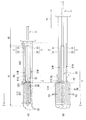
- FIG. 2 is a schematic side view (YZ side view) of an example of the detailed configuration inside the cover 3 shown in FIG.
- FIG. 2A schematically shows a detailed configuration example of the cover 3, the stent graft 2 therein, the distal end region A1 of the delivery shaft 11, and the like in a side view.
- FIG. 2B is a schematic side view showing an example of an operation mode when the stent graft 2 is expanded in the configuration example shown in FIG. 2A.
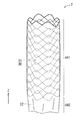
- FIG. 3 is a perspective view schematically showing a detailed configuration example of the stent graft 2 shown in FIG.
- the stent graft 2 has a tubular (cylindrical) structure extending along its axial direction (Z-axis direction). , A stent 21 and a graft 22.
- the stent graft 2 has a self-expanding structure that can be held in a reduced diameter state.
- the length of the stent graft 2 along the axial direction is, for example, about 2 to 30 cm.
- the outer diameter of the stent graft 2 when expanded is, for example, about 6 to 46 mm.
- the stent 21 is configured using one or a plurality of wires W (element wires) as shown in FIG. 3, for example, and has a tubular (cylindrical) structure in this example.
- the tubular structure is formed of a mesh structure, and such a tubular mesh structure is formed by braiding the wire W in a predetermined pattern.
- this braided pattern for example, plain weave, knitted stitch, and the like can be mentioned.
- the wire rod W may be bent in a zigzag shape and processed into a cylindrical shape, and one or more wires may be arranged to form a cylindrical mesh structure.
- a metal wire is preferable, and in particular, a shape memory alloy to which a shape memory effect or superelasticity is imparted by heat treatment is preferably employed.
- a shape memory alloy to which a shape memory effect or superelasticity is imparted by heat treatment.
- stainless steel, tantalum (Ta), titanium (Ti), platinum (Pt), gold (Au), tungsten (W), or the like may be used as the material of the wire W.
- a wire W for example.
- a wire obtained by coating a surface of a metal wire with Au, Pt, or the like by plating or a composite wire in which a core material made of a radiopaque material such as Au, Pt is covered with an alloy is used. It may be used as W.
- the graft 22 has a tubular (cylindrical) shape, for example, as shown in FIG. 3, and is arranged so as to cover (cover) at least a part of the stent 21.
- the graft 22 is disposed so as to cover the inner peripheral side or the outer peripheral side of the stent 21 (wire W), or the graft 22 is disposed on the outer peripheral side and the inner peripheral side of the stent 21 (wire W).
- the stent graft 2 is provided with a stent arrangement area A41 and a non-stent arrangement area A42 along the axial direction (Z-axis direction).
- the stent arrangement area A41 is an area where the stent 21 is arranged on the graft 22 (both the stent 21 and the graft 22 are present).
- the stent non-arranged area A42 is an area where the stent 21 is not arranged on the graft 22 (only the graft 22 exists).
- the graft 22 is connected to the stent 21 by, for example, sewing, bonding, welding, or the like.
- a connection portion between the graft 22 and the stent 21 is appropriately provided, for example, at both ends and an intermediate portion of the stent 21.
- a graft 22 for example, a thermoplastic resin formed into a tubular shape by a molding method such as extrusion molding or blow molding, or a knitted or woven fabric formed of a thermoplastic resin fiber or a fine metal wire formed in a tubular shape , A non-woven fabric made of a thermoplastic resin or a fine metal formed in a cylindrical shape, a sheet or porous sheet of a flexible resin formed in a cylindrical shape, a structure in which the resin is formed into a thin cylindrical shape by an electrospinning method, and the like. Can be used.
- a known knitted fabric or woven fabric such as plain weave, twill weave, or knitting can be used.
- a material with a fold such as crimping can be used.
- a knitted and woven fabric of thermoplastic resin fibers formed in a tubular shape, and a plain woven fabric of thermoplastic resin fibers formed in a tubular shape are particularly excellent in strength, porosity, and productivity. It can be said that it is preferable.
- thermoplastic resin examples include polyolefins such as polyethylene, polypropylene, and ethylene- ⁇ -olefin copolymer, polyamide, polyurethane, polyethylene terephthalate, polybutylene terephthalate, polycyclohexane terephthalate, and polyethylene-2,6-naphthalate.
- a resin having low durability and little tissue reaction such as a polyester resin and a fluororesin such as polyfluoroethylene and polyfluoropropylene.
- polyesters such as polyethylene terephthalate, and fluororesins such as polyfluoroethylene and polyfluoropropylene, which are chemically stable, have high durability, and have low tissue reaction, can be preferably used.
- the cover 3 is a member for holding at least a portion of the stent graft 2 where the stent 21 is arranged (at least the stent arrangement region A41) in the distal end region A1 of the delivery shaft 11 in a reduced diameter state. is there.
- the above-described stent arrangement area A41 is located on the distal end side of the delivery shaft 11, and the above-described non-stent arrangement area A42 is located at the base end of the delivery shaft 11.
- the stent graft 2 is retained in the cover 3 in a laterally oriented orientation.
- the outer diameter of the cover 3 is, for example, about 5.0 to 20.0 mm, preferably about 7.5 to 15.0 mm, and 10.0 mm in a preferred example.
- a cover 3 is formed of a soft cover in this example.
- the cover 3 is soft, the cover 3 can easily follow the shape change of the distal end region A1 of the delivery shaft 11 as compared with a hard tubular body (sheath) or the like. I have.
- the cover 3 has a two-layer structure (double structure) having an inner layer 31 and an outer layer 32. That is, the cover 3 has a cylindrical outer layer portion 32 and an inner layer portion 31 located on the inner peripheral side of the outer layer portion 32.
- the cover 3 is provided with a folded portion 33 that connects (connects) the outer layer portion 32 and the inner layer portion 31 at the distal end side of the delivery shaft 11.
- the cover 3 is formed by folding a tubular tube material inward, and the folded portion corresponds to the inner layer portion 31. Further, as shown in FIG.
- the stent graft 2 held in a reduced diameter state on the inner peripheral side of the inner layer portion 31 has its distal end located on the folded portion 33 side of the cover 3.
- the stent graft 2 is arranged between the folded portion 33 and the base end of the inner layer portion 31.
- an operation for expanding the stent graft 2 is performed as shown in FIG. 2B, for example. That is, first, the proximal end of the outer layer portion 32 is pulled in the proximal direction of the delivery shaft 11 (the direction opposite to the folded portion 33) by the operator of the catheter 1 (see the arrow P1). Then, the inner layer portion 31 is turned off from the outer periphery of the stent graft 2 and is removed from the stent graft 2 (see arrow P2). As a result, the stent graft 2 is gradually expanded (deployed) from the distal end side by the self-expanding force of the stent 21 (see arrow P3).
- the force for pulling out the cover 3 when performing the above-described pulling operation is affected by the frictional resistance between the outer surface of the inner layer portion 31 and the inner surface of the outer layer portion 32.
- the expansion force of the stent graft 2 is not affected. Therefore, even when the expansion force of the stent graft 2 is strong, the stent graft 2 can be reliably deployed.
- FIGS. 5A and 5B schematically show a detailed configuration example of the cover 3 shown in FIG.
- the inner layer 31 of the cover 3 is a portion having a relatively small diameter (inner diameter Rs) in the inner layer 31.
- a small diameter portion 31S (a constricted portion) is provided.
- the small diameter portion 31S extends along the axial direction (Z-axis direction) of the inner layer portion 31 near the proximal end of the stent 21 in the stent graft 2 (stent arrangement). (Near the boundary between the region A41 and the non-stent arrangement region A42).
- the diameter of the inner layer portion 31 extends from the folded portion 33 to the small diameter portion 31S along the axial direction (Z-axis direction) of the inner layer portion 31. And gradually (tapered). Similarly, the diameter of the inner layer portion 31 gradually (in a tapered shape) also decreases from the base end of the inner layer portion 31 toward the small diameter portion 31S along the axial direction (Z-axis direction) of the inner layer portion 31. (See FIGS. 2A and 4A).
- the inner diameter Rs of the small diameter portion 31S is larger than the outer diameter Re of the above-described enlarged diameter portion 114 of the delivery shaft 11. (Rs> Re). Conversely, the outer diameter Re of the enlarged diameter portion 114 is smaller than the inner diameter Rs of the small diameter portion 31S.
- the above-described two-layer structure double structure
- the cover 3 having, for example, the structure shown in FIG. 5A (the structure in which the small diameter portion 31S is arranged in the region closer to the distal end than the center along the Z-axis direction) is prepared.
- the front end portion of the cover 3 is folded back toward the base end at the folded portion 33.
- the distal end portion (the folded portion) serving as the inner layer portion 31 is inserted into the inner peripheral side of the base end side cover 3 serving as the outer layer portion 32, and the distal end portion is folded back. .
- the cover 3 having a two-layer structure including the small diameter portion 31S described above is formed.
- each portion of the cover 3 is, for example, in the following numerical range (see FIGS. 5A and 5B).
- Outer diameter R31 of inner layer portion 31 (corresponding to the inner diameter of outer layer portion 32): about 10 mm to 18 mm.
- Outer diameter R32 of outer layer section 32 (> R31): about 16 mm to 18 mm.
- the length from the distal end of the cover 3 in FIG. 5 (A) to the small diameter portion 31S ... about 80 ⁇ 3 mm.
- the length from the base end of the cover 3 to the small diameter portion 31S in FIG. Approximately 2 mm ⁇ Length (total length) from the distal end to the proximal end of the cover 3 in FIG.
- Such a cover 3 (the above-mentioned soft cover) is made of, for example, a low elastic material.
- a low elasticity material for example, a material having a lower elasticity than the above-mentioned stent can be used.
- such low-stretch materials include, for example, polypropylene, polyolefin such as ethylene- ⁇ -olefin copolymer, polyamide, polyurethane, polyethylene terephthalate, polybutylene terephthalate, polycyclohexane terephthalate, polyethylene-2, Polyester such as 6-naphthalate, fluororesin such as polyfluoroethylene and polyfluorinated propylene, resins having high tensile strength such as polyetheretherketone and liquid crystal polymer, and resins having low durability and little tissue reaction can be used.
- polypropylene polyolefin such as ethylene- ⁇ -olefin copolymer, polyamide, polyurethane, polyethylene terephthalate, polybutylene terephthalate, polycyclohexane terephthalate, polyethylene-2, Polyester such as 6-naphthalate, fluororesin such as polyfluoroethylene and polyfluorinated propylene, resins having high ten
- materials that are chemically stable, have high durability, and have little tissue reaction include, for example, polyesters such as polyethylene terephthalate, fluororesins such as polyethylene fluoride and polypropylene propylene, and nylons and the like. Examples thereof include polyamide, polyetheretherketone, and liquid crystal polymer.
- the treatment device 4 is used, for example, when treating an aneurysm including arterial dissection.
- the stent graft 2 in a state of reduced diameter is carried to a part to be treated (for example, inside a blood vessel such as an artery) in a patient, and is placed after being expanded. .
- the stent graft 2 is used, for example, in the treatment using the OSG method, which is one of the treatment methods for arterial dissection in the thoracic aorta.
- FIG. 6 is a schematic diagram illustrating an example of a method of using the treatment device 4 during this treatment.
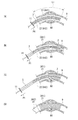
- FIG. 7 (FIGS. 7 (A) to 7 (D)) is a schematic diagram showing an example of the method of placing the stent graft 2 during this treatment.
- the artery 9 thoracic aorta
- an aneurysm in the artery 9 to be treated is shown as an aneurysm 90.
- a part of the artery 9 is incised after the patient's thoracotomy using the treatment apparatus 4 having the configuration shown in FIGS.
- the stent graft 2 in a reduced diameter is inserted from the opening h (see arrow P4). Specifically, the stent graft 2 is inserted from the distal end side (the cover 3 side) of the delivery shaft 11 in the catheter 1. At this time, for example, as shown in FIGS. 1 and 2, the stent graft 2 is held inside the cover 3 in a state where the diameter of the stent graft 2 is reduced in the distal end region A1 of the delivery shaft 11 in the catheter 1.
- the catheter 1 is inserted along a predetermined guide wire in order to avoid the possibility that the catheter 1 is erroneously inserted into the false lumen. That is, the catheter 1 is inserted while such a guidewire is inserted into a small hole (for example, a lumen L described later) in the catheter 1.
- a guide wire is inserted into the artery 9 from the base (groin) of the patient's foot, and is pulled out from the opening h through the artery 9.
- the length of such a guide wire is, for example, about 50 to 450 cm, and its outer diameter is, for example, about 0.2 to 1.0 mm.
- the catheter 1 is inserted into the artery 9 so that the opening h is used as an entrance and along the guide wire (see arrow P4).
- the catheter 1 since the guide wire is securely inserted into the true lumen, by inserting the catheter 1 into the artery 9 along the guide wire, the catheter 1 is also securely inserted. It will be inserted into the true cavity. That is, even in the case of the arterial dissection, the possibility that the catheter 1 is inserted into the false lumen is avoided.
- the stent graft 2 is caused to reach a part of the artery 9 beyond the part to be treated (near the place where the aneurysm 90 is formed) using the treatment apparatus 4. (See arrow P4).
- an operation of expanding (deploying) the stent graft 2 by using the self-expanding force of the stent 21 is performed. Specifically, first, the operator of the catheter 1 pulls the proximal end of the outer layer 32 of the cover 3 in the proximal direction of the delivery shaft 11 (see arrow P1). Then, the inner layer portion 31 is turned off from the outer periphery of the stent graft 2 and is removed from the stent graft 2 (see the arrow P2 in FIGS. 2B and 4B described above). As a result, the stent graft 2 gradually expands from the distal end side by the self-expanding force of the stent 21 (see arrow P3).
- the stent graft 2 is fixed to the inner wall of the artery 9.
- the lumen of the artery 9 near the location where the aneurysm 90 is formed is expanded and retained.
- the proximal end of the stent graft 2 and the artery 9 are sutured by suturing.
- an artificial blood vessel different from the stent graft 2 may be anastomosed with the anastomotic portion.
- the following method is compared with a treatment method (conventional treatment method) in which a catheter is inserted from the base of the patient's foot (groin) to carry a stent graft to a treatment target site.
- Benefits are obtained. That is, there is obtained an advantage that it is possible to treat a site (for example, an arch aorta) where an important branch exists, which is extremely difficult to treat with this conventional treatment method.
- the descending aortic suture (peripheral anastomosis) is replaced by fixation by the stent graft 2. That is, in the OSG method, the anastomosis between the distal end of the stent graft 2 and the descending aorta is omitted, so that the anastomosis operation is simplified.
- the operation time (extracorporeal circulation time) can be shortened, and further, since the left thoracotomy or large thoracotomy required for suturing the descending aorta is avoided, the surgical invasion to the patient is reduced (treatment The burden on the patient in the event is reduced).
- the OSG method has an advantage that a transplantation range of an artificial blood vessel can be set in a wide range, and a surgical treatment for a nearby complication can be performed.
- the stent graft applied to the OSG method is not introduced from the groin as in the above-described conventional treatment method, it is not necessary to pass through a small blood vessel, and even if the outer diameter is reduced to some extent even in a reduced diameter state. It can be large (thick).
- the cover 3 is configured as follows. That is, the inner layer portion 31 of the cover 3 is provided with a small diameter portion 31S which is a portion having a relatively small diameter. For this reason, since the gap (space) between the inner layer portion 31 and the outer layer portion 32 in the cover 3 becomes large (see reference sign G in FIGS. 4A and 4B), the inner layer portion 31 and the outer layer portion are formed. Friction with the portion 32 (friction between the outer surface of the inner layer portion 31 and the inner surface of the outer layer portion 32) is less likely to occur.
- the stent graft 2 in which at least the portion where the stent 21 is arranged (stent arrangement region A41) is in a reduced diameter state is used for the artery 9 or the like using the catheter 1 held in the distal end region A1.
- the following is performed. That is, at the time of such treatment, the operation of pulling the base end side of the outer layer portion 32 of the cover 3 in the base end direction of the delivery shaft 11 (pulling operation) can be easily performed by the operator. Therefore, in the present embodiment, it is possible to improve the convenience of the treatment by performing the treatment using the treatment device 4 including the cover 3.
- the diameter of the inner layer portion 31 in the cover 3 gradually (in a tapered shape) from the folded portion 33 toward the small diameter portion 31S along the axial direction (Z-axis direction) of the delivery shaft 11. is decreasing. Accordingly, in the present embodiment, for example, when the diameter of the inner layer portion 31 is reduced stepwise when the stent graft 2 in the reduced diameter state is expanded from the inside of the cover 3 and expanded by the above-described pulling operation, etc. Compared to That is, since the diameter of the inner layer portion 31 is continuously reduced, a gap is always generated between the inner layer portion 31 and the outer layer portion 32. Therefore, the friction between the inner layer portion 31 and the outer layer portion 32 is reduced. It is even less likely to occur, and the above-described pulling operation can be performed more easily for the operator. As a result, in the present embodiment, it is possible to further improve the convenience during treatment.
- the cover 3 is formed using the above-described low-stretch material, the gap between the inner layer portion 31 and the outer layer portion 32 can be more reliably maintained, and the inner layer portion can be maintained.
- the friction between the outer layer portion 32 and the outer layer portion 31 is less likely to be generated, and the force is easily transmitted when performing the above-described pulling operation.
- the convenience at the time of treatment can be further improved.
- the enlarged diameter portion 114 is provided in the distal end region A1 of the delivery shaft 11, and the outer diameter Re of the enlarged diameter portion 114 is smaller than the inner diameter Rs of the small diameter portion 31S ( Re ⁇ Rs: see FIG. 4 (A)).
- the gap between the enlarged diameter portion 114 and the small diameter portion 31S is increased.
- the proximal side of the graft 22 can be arranged closer to the proximal side than the enlarged diameter portion 114.
- such a small-diameter portion 31S is provided near the base end of the stent 21 along the axial direction (Z-axis direction) of the inner layer portion 31, so that it is as follows. That is, when the stent graft 2 in the reduced diameter state is expanded from the inside of the cover 3 and expanded in diameter by the above-described pulling operation, the period until the deployment of the portion where the stent 21 is disposed (stent arrangement region A41) is completed. The gap between the inner layer 31 and the outer layer 32 can be maintained. Therefore, friction between the inner layer portion 31 and the outer layer portion 32 is less likely to occur, and the above-described pulling operation can be performed more easily for the operator. As a result, in the present embodiment, the convenience at the time of treatment can be further improved.
- the inner layer 31 is turned up to become the outer layer 32, and the outer diameter of the inner layer 31 becomes the inner diameter of the outer layer 32.
- the outer diameter of the inner layer portion 31 is as follows. That is, in the area where the stent 21 is arranged (stent arrangement area A41), the outer diameter of the inner layer portion 31 on the proximal side is smaller than the outer diameter of the inner layer portion 31 on the distal side.
- the cover 3 is turned up by the above-described pulling operation, the outer diameter of the inner layer 31 located in the inner layer becomes smaller than the inner diameter of the outer layer 32 that has been turned. Therefore, when turning over the cover 3 covering the stent arrangement area A41, a gap is generated between the inner layer portion 31 and the outer layer portion 32. As a result, friction between the inner layer portion 31 and the outer layer portion 32 is less likely to occur.
- each member described in the above embodiment are not limited, and may be other shapes, arrangement positions, sizes, numbers, materials, and the like.
- the enlarged diameter portion may not be provided near the boundary between the stent arrangement region and the stent non-arrangement region in the delivery shaft.
- the present invention is not limited to this case. That is, for example, the inner layer portion and the outer layer portion of the cover are separate from each other, and the inner layer portion and the outer layer portion are connected (connected) by a separate folded portion (connection portion). You may do so.
- the shape, arrangement position, size, number, material, and the like of the small diameter portion and the like in the inner layer portion of the cover are not limited to those described in the above embodiment, and other shapes, arrangement positions, sizes, numbers, materials, and the like. And so on.
- the diameter of the inner layer portion may be reduced stepwise (rather than tapered) from the folded portion to the smaller diameter portion.
- the diameter of the inner layer portion may not be changed in a portion from the base end to the small diameter portion.
- the material forming the cover may be a material that does not have low elasticity (for example, compared to a stent or the like).
- the outer diameter of the enlarged diameter portion of the delivery shaft may be equal to or larger than the inner diameter of the small diameter portion of the inner layer portion of the cover.
- the small diameter portion in the inner layer of the cover may be provided in a region other than the vicinity of the proximal end of the stent in the inner layer.
- one stent arrangement region arranged on the distal side in the cover and one stent non-arrangement region arranged on the proximal side in the cover are provided.
- another stent non-arrangement region may be further provided on the distal end side of the stent arrangement region in the stent graft.
- the stent arrangement region may be interposed between the non-stent arrangement region and the other stent non-arrangement region.
Landscapes
- Health & Medical Sciences (AREA)
- Engineering & Computer Science (AREA)
- Biomedical Technology (AREA)
- Cardiology (AREA)
- Oral & Maxillofacial Surgery (AREA)
- Transplantation (AREA)
- Heart & Thoracic Surgery (AREA)
- Vascular Medicine (AREA)
- Life Sciences & Earth Sciences (AREA)
- Animal Behavior & Ethology (AREA)
- General Health & Medical Sciences (AREA)
- Public Health (AREA)
- Veterinary Medicine (AREA)
- Media Introduction/Drainage Providing Device (AREA)
- Prostheses (AREA)
Abstract
La présente invention concerne un dispositif de traitement capable d'améliorer la commodité durant un traitement. Ledit dispositif de traitement (4) est muni : d'un cathéter (1) comportant une tige de distribution (11) s'étendant dans un sens axial (sens de l'axe des Z) ; une greffe d'endoprothèse (2) conçue pour inclure une greffe cylindrique (22) et une endoprothèse (21) ; et un couvercle (3) pour contenir, sous un état de diamètre réduit, au moins une partie (au moins une région de configuration d'endoprothèse (A41)) de la greffe d'endoprothèse (2) dans laquelle l'endoprothèse (21) est disposée dans la greffe d'endoprothèse (2) au niveau de la région d'extrémité distale (A1) de la tige de distribution (11). Le couvercle (3) présente : une partie de couche externe (32) cylindrique ; une partie de couche interne (31) qui est positionnée sur le côté périphérique interne de la partie de couche externe (32) et dans laquelle au moins la région de configuration d'endoprothèse (A41) est maintenue dans un état de diamètre réduit sur son côté périphérique interne ; une partie pliée (33) qui relie la partie de couche externe (32) et la partie de couche interne (31) sur le côté d'extrémité distale de la tige de distribution (11) ; et une partie de petit diamètre (31S) qui est une partie de la partie de couche interne (31) dans laquelle le diamètre est relativement petit.
Priority Applications (2)
| Application Number | Priority Date | Filing Date | Title |
|---|---|---|---|
| PCT/JP2018/035547 WO2020065742A1 (fr) | 2018-09-26 | 2018-09-26 | Dispositif de traitement |
| JP2020547651A JP6960544B2 (ja) | 2018-09-26 | 2018-09-26 | 治療装置 |
Applications Claiming Priority (1)
| Application Number | Priority Date | Filing Date | Title |
|---|---|---|---|
| PCT/JP2018/035547 WO2020065742A1 (fr) | 2018-09-26 | 2018-09-26 | Dispositif de traitement |
Publications (1)
| Publication Number | Publication Date |
|---|---|
| WO2020065742A1 true WO2020065742A1 (fr) | 2020-04-02 |
Family
ID=69952942
Family Applications (1)
| Application Number | Title | Priority Date | Filing Date |
|---|---|---|---|
| PCT/JP2018/035547 Ceased WO2020065742A1 (fr) | 2018-09-26 | 2018-09-26 | Dispositif de traitement |
Country Status (2)
| Country | Link |
|---|---|
| JP (1) | JP6960544B2 (fr) |
| WO (1) | WO2020065742A1 (fr) |
Cited By (1)
| Publication number | Priority date | Publication date | Assignee | Title |
|---|---|---|---|---|
| WO2026070804A1 (fr) * | 2024-09-30 | 2026-04-02 | テルモ株式会社 | Dispositif médical et procédé d'expansion |
Citations (2)
| Publication number | Priority date | Publication date | Assignee | Title |
|---|---|---|---|---|
| JP2002529139A (ja) * | 1998-11-06 | 2002-09-10 | ボストン サイエンティフィック リミテッド | 改良型回転式メンブレンステント送り出しシステム |
| JP2018075277A (ja) * | 2016-11-11 | 2018-05-17 | 日本ライフライン株式会社 | 治療装置 |
-
2018
- 2018-09-26 WO PCT/JP2018/035547 patent/WO2020065742A1/fr not_active Ceased
- 2018-09-26 JP JP2020547651A patent/JP6960544B2/ja active Active
Patent Citations (2)
| Publication number | Priority date | Publication date | Assignee | Title |
|---|---|---|---|---|
| JP2002529139A (ja) * | 1998-11-06 | 2002-09-10 | ボストン サイエンティフィック リミテッド | 改良型回転式メンブレンステント送り出しシステム |
| JP2018075277A (ja) * | 2016-11-11 | 2018-05-17 | 日本ライフライン株式会社 | 治療装置 |
Cited By (1)
| Publication number | Priority date | Publication date | Assignee | Title |
|---|---|---|---|---|
| WO2026070804A1 (fr) * | 2024-09-30 | 2026-04-02 | テルモ株式会社 | Dispositif médical et procédé d'expansion |
Also Published As
| Publication number | Publication date |
|---|---|
| JP6960544B2 (ja) | 2021-11-05 |
| JPWO2020065742A1 (ja) | 2021-02-15 |
Similar Documents
| Publication | Publication Date | Title |
|---|---|---|
| US9402634B2 (en) | Device and method for treating vascular abnormalities | |
| JP4627687B2 (ja) | ステントの挿入装置 | |
| JP2012501734A (ja) | 対象部位を治療するための分岐した医療用具、及び関連する方法 | |
| WO2019171694A1 (fr) | Dispositif de traitement d'aorte | |
| JP2013048778A (ja) | 管状器官の治療装置 | |
| JP6200465B2 (ja) | ステントグラフト | |
| KR102137333B1 (ko) | 치료 장치 | |
| JP6960544B2 (ja) | 治療装置 | |
| JP6676424B2 (ja) | 治療装置 | |
| JP7549147B2 (ja) | 治療装置 | |
| JP7532001B2 (ja) | 治療装置 | |
| JP2005058459A (ja) | ステントグラフトの縮径保持方法 | |
| JP6899343B2 (ja) | 治療装置 | |
| WO2021176673A1 (fr) | Arbre de distribution et système de distribution | |
| WO2021176672A1 (fr) | Arbre de distribution et système de distribution |
Legal Events
| Date | Code | Title | Description |
|---|---|---|---|
| 121 | Ep: the epo has been informed by wipo that ep was designated in this application |
Ref document number: 18935033 Country of ref document: EP Kind code of ref document: A1 |
|
| ENP | Entry into the national phase |
Ref document number: 2020547651 Country of ref document: JP Kind code of ref document: A |
|
| NENP | Non-entry into the national phase |
Ref country code: DE |
|
| 122 | Ep: pct application non-entry in european phase |
Ref document number: 18935033 Country of ref document: EP Kind code of ref document: A1 |