WO2020065748A1 - Appareillage de commutation - Google Patents
Appareillage de commutation Download PDFInfo
- Publication number
- WO2020065748A1 WO2020065748A1 PCT/JP2018/035587 JP2018035587W WO2020065748A1 WO 2020065748 A1 WO2020065748 A1 WO 2020065748A1 JP 2018035587 W JP2018035587 W JP 2018035587W WO 2020065748 A1 WO2020065748 A1 WO 2020065748A1
- Authority
- WO
- WIPO (PCT)
- Prior art keywords
- switchgear
- main
- buses
- main bus
- branch
- Prior art date
- Legal status (The legal status is an assumption and is not a legal conclusion. Google has not performed a legal analysis and makes no representation as to the accuracy of the status listed.)
- Ceased
Links
Images


Classifications
-
- H—ELECTRICITY
- H02—GENERATION; CONVERSION OR DISTRIBUTION OF ELECTRIC POWER
- H02B—BOARDS, SUBSTATIONS OR SWITCHING ARRANGEMENTS FOR THE SUPPLY OR DISTRIBUTION OF ELECTRIC POWER
- H02B1/00—Frameworks, boards, panels, desks, casings; Details of substations or switching arrangements
- H02B1/20—Bus-bar or other wiring layouts, e.g. in cubicles, in switchyards
- H02B1/22—Layouts for duplicate bus-bar selection
-
- H—ELECTRICITY
- H02—GENERATION; CONVERSION OR DISTRIBUTION OF ELECTRIC POWER
- H02B—BOARDS, SUBSTATIONS OR SWITCHING ARRANGEMENTS FOR THE SUPPLY OR DISTRIBUTION OF ELECTRIC POWER
- H02B1/00—Frameworks, boards, panels, desks, casings; Details of substations or switching arrangements
- H02B1/20—Bus-bar or other wiring layouts, e.g. in cubicles, in switchyards
-
- H—ELECTRICITY
- H02—GENERATION; CONVERSION OR DISTRIBUTION OF ELECTRIC POWER
- H02B—BOARDS, SUBSTATIONS OR SWITCHING ARRANGEMENTS FOR THE SUPPLY OR DISTRIBUTION OF ELECTRIC POWER
- H02B11/00—Switchgear having carriage withdrawable for isolation
- H02B11/12—Switchgear having carriage withdrawable for isolation with isolation by horizontal withdrawal
Definitions
- This application relates to a switchgear in which circuit breakers are stacked in two stages.
- a switchgear in which circuit breakers are stacked in two stages can significantly reduce the space required for arrangement as compared with a conventional switchgear having only one circuit breaker, and is effective as a space-saving switchgear. It is.
- the main bus connected to the upper circuit breaker works from the ceiling portion of the switchgear, and the main bus connected to the lower circuit breaker is a switch.
- the connection operation is performed from the back of the gear (for example, see Patent Document 1).
- connection work is generally performed from behind the switchgear. I do. At this time, it is necessary to remove the main bus conductor to which the power cable is connected, so that a high technical level is required and a long time is required.
- the present application has been made to solve the above-described problem, and has an object to make it possible to easily and quickly connect a main bus in a switchgear installation operation.
- the switchgear of the present application is a switchgear in which circuit breakers are stacked in two stages, an upper stage and a lower stage of the switchgear, wherein the width direction is longer than the thickness direction, has a flat surface, and extends in the lateral direction.
- the lower three main buses have a main bus arrangement structure in which the flat surfaces face each other and are arranged in parallel in the vertical direction.
- the switchgear of the present application can easily and quickly connect the main bus conductor in the installation work.
- FIG. 2 is a side sectional view of the switchgear according to the first embodiment.
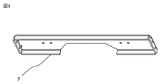
- FIG. 2 is a layout view of a main bus and power cable connection conductors observed from a cross section XX in FIG. 1. It is a perspective view of the support frame which holds a main bus.
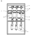
- FIG. 2 is a perspective view showing an arrangement of a main bus and branch buses observed from a YY cross section in FIG. 1.
- FIG. 1 is a side sectional view of the switchgear of the present embodiment
- FIG. 2 is a layout view of a main bus bar and a power cable connection conductor when observed from a cross section XX of the switchgear.
- the switchgear 1 is a two-stage stacking arrangement having circuit breakers 10 in the upper and lower stages, and has three-phase main buses 4a and 4b in the upper and lower stages.
- the switchgear 1 has an operation surface 11 on the left side in FIG. 1, and includes a circuit breaker 10 and a control room 8 in portions adjacent to the upper and lower operation surfaces.
- a back door 9 is provided at the right end, and a cable room 3 is disposed inside the back door 9.
- power cable connecting conductors 5 each having a current transformer 13 attached thereto are connected to a grounding switch 12.
- the main bus chamber 2 is arranged in the upper and lower stages of the central part of the switchgear 1.
- the main buses 4a and 4b are shown as rectangular in cross section in FIG. 1, they are rod-shaped conductors having a flat surface longer in the width direction than in the thickness direction, and extend long in the vertical direction of the paper. I have.
- the upper main bus 4a has a triangular arrangement, and one of the three main buses 4a is disposed in front of the switchgear 1.
- the work can be relatively easily performed by performing the connection work from the upper surface of the switchgear 1 in the installation work.
- the lower main bus 4b needs to be installed from the back of the switchgear 1. If the lower main bus 4b is also arranged in a triangular manner as in the upper row, it is difficult to connect the main bus 4b arranged in front of the switchgear 1 from the back, and a part of the main bus 4b is removed. It is necessary to carry out connection work, which requires a high technical level and requires a long working time.
- the lower main buses 4b are attached in a layout extending in the direction perpendicular to the paper with the flat surfaces facing each other, and the three main buses 4b are It differs from the conventional main bus arrangement of the triangular arrangement in that it is arranged in parallel in the vertical direction.
- FIG. 2 shows the relationship between the arrangement of the main buses 4b and the power cable connection conductors 5 as viewed from the back of the switch gear 1 along the line XX.
- the power cable connection conductor 5 is common to the main bus bar 4b in that it is a rod-shaped conductor having a flat surface.
- the three power cable connection conductors 5 are attached side by side with the flat surface facing in the front-rear direction of the device, and are arranged orthogonal to the arrangement of the main buses 4b.
- three main buses are provided on the back side (the back side of the paper surface of FIG. 2) of the three power cable connection conductors 5 arranged in the horizontal direction. 4b are arranged in the vertical direction, and in the installation work, the connection work of the main bus 4b can be performed through the gap of the power cable connection conductor 5 from the back side. Therefore, it is not necessary to remove the main bus 4b, and the installation work can be easily performed.
- the three main buses 4b each extend in the horizontal direction, and are arranged in the vertical direction with their flat surfaces facing each other.
- the main bus 4b it is necessary to take out and arrange three branch buses 6 for connecting each main bus 4b to the circuit breaker 10 and the like. It is difficult to arrange the branch bus 6.
- the lower main buses 4b are arranged so that the main buses 4b are close to each other as compared with a conventional triangular arrangement, and it is expected that the influence of the electromagnetic force between them will increase.
- FIGS a solution to these problems will be described mainly with reference to FIGS.
- FIG. 3 shows a perspective view of the support frame 7.
- the support frame 7 is made of iron, and the strength can be increased by bending four sides.
- the main bus bar 4 b located at the center of the three is fixed via the insulator 14.
- the main bus bar 4b can be firmly attached, and it is possible to cope with the influence of the electromagnetic force.
- FIG. 4 is a perspective view of the lower main bus chamber 2 observed from the YY cross section of FIG. 1 and shows the arrangement of the main bus 4 b and the branch bus 6.
- each main bus bar 4b has a flat bar shape and extends in the horizontal direction in FIG. Further, the three main buses 4b are linearly arranged in the vertical direction with flat surfaces facing each other.
- a branch bus 6 is connected to each main bus 4b.
- the main bus 4b and the branch bus 6 are connected at different positions without the lateral positions overlapping each other. That is, in the example of FIG. 4, the uppermost main bus 4b is on the right, the lowermost main bus 4b is on the left, the center main bus 4b is at the center, and the main bus 4b and the branch bus 6 are connected. . Thereby, the gaps between the main buses 4b, between the branch buses 6, and between the main bus 4b and the branch buses 6 can be increased, and the influence of the mutual electromagnetic force can be reduced.
- connection positions of the three main buses 4b and the branch buses 6 are different from each other so that the positions in the horizontal direction do not overlap with each other, and need not necessarily be the left, right, and center as described above. Further, the intervals do not need to be equal, and the connection positions may be arranged rightward or leftward. Further, the relationship between this connection position and the arrangement of the power cable connection conductor 5 adjacent to the main bus 4b is not particularly limited, and coincides with the position where the main bus 4b and the power cable connection conductor 5 overlap and intersect. Alternatively, a connection position between the main bus 4b and the branch bus 6 may be arranged in a gap portion of the arrangement of the power cable connection conductors 5.
- the main bus 4b located at the center of the three main buses 4b is fixed to the iron support frame 7 via the insulator 14 as described above.
- the branch busbar 6 connected to the main busbar 4b and the support frame 7 are close to each other, and there is a fear that the influence of the electromagnetic force will be greater than that of the other main busbars 4b. Therefore, in the present embodiment, the branch bus 6 has a shape bent downward so as to pass through a position distant from the support frame 7, and the support frame 7 also secures a distance from the branch bus 6. Therefore, a part is concave.
- the concave shape formed in the support frame 7 is trapezoidal, but is not limited thereto, and a concave shape such as a square or a circle may be used. it can. Further, in the present embodiment, one concave shape is provided, but a plurality of concave shapes may be provided as necessary.
- the insulation distance between the support frame 7 and the branch bus bar 6 can be kept large.
- the effect of the electromagnetic force can be reduced.
- the three main buses 4b are arranged in the vertical direction while extending in the horizontal direction.
- the influence of the electromagnetic force can be reduced by setting the connection positions of the main buses 4b and the branch buses 6 to different positions without overlapping each other when viewed in the lateral direction.
- the central main bus bar 4b is fixed with high strength using an iron support frame 7, and a concave portion is provided in the support frame 7 at a portion where the branch bus bar 6 and the support frame 7 are close to each other.
- the bent shape away from 7 keeps the insulation distance large and prevents the influence of electromagnetic force.
Landscapes
- Engineering & Computer Science (AREA)
- Power Engineering (AREA)
- Patch Boards (AREA)
Abstract
La présente invention porte sur un appareillage de commutation dans lequel il est possible d'effectuer une partie d'un travail d'installation d'un appareillage de commutation empilé à deux niveaux, qui consiste en un travail de connexion de conducteurs dans l'appareillage de commutation du niveau inférieur, sans retirer un bus. L'appareillage de commutation (1), dans lequel des disjoncteurs (10) sont disposés dans un niveau supérieur et un niveau inférieur de l'empilement à deux niveaux de l'appareillage de commutation (1), est caractérisé en ce que trois bus principaux (4b) du niveau inférieur, qui sont plus longs dans la direction de la largeur que la direction de l'épaisseur, qui présentent une surface plate et qui s'étendent dans la direction horizontale, sont configurés dans une structure de disposition de bus principaux dans laquelle les surfaces plates sont placées en opposition réciproque de façon à être alignées en parallèle dans la direction verticale.
Priority Applications (3)
| Application Number | Priority Date | Filing Date | Title |
|---|---|---|---|
| PCT/JP2018/035587 WO2020065748A1 (fr) | 2018-09-26 | 2018-09-26 | Appareillage de commutation |
| JP2019512012A JP6556408B1 (ja) | 2018-09-26 | 2018-09-26 | スイッチギヤ |
| DE112018008025.0T DE112018008025T5 (de) | 2018-09-26 | 2018-09-26 | Schaltanlage |
Applications Claiming Priority (1)
| Application Number | Priority Date | Filing Date | Title |
|---|---|---|---|
| PCT/JP2018/035587 WO2020065748A1 (fr) | 2018-09-26 | 2018-09-26 | Appareillage de commutation |
Publications (1)
| Publication Number | Publication Date |
|---|---|
| WO2020065748A1 true WO2020065748A1 (fr) | 2020-04-02 |
Family
ID=67539811
Family Applications (1)
| Application Number | Title | Priority Date | Filing Date |
|---|---|---|---|
| PCT/JP2018/035587 Ceased WO2020065748A1 (fr) | 2018-09-26 | 2018-09-26 | Appareillage de commutation |
Country Status (3)
| Country | Link |
|---|---|
| JP (1) | JP6556408B1 (fr) |
| DE (1) | DE112018008025T5 (fr) |
| WO (1) | WO2020065748A1 (fr) |
Citations (7)
| Publication number | Priority date | Publication date | Assignee | Title |
|---|---|---|---|---|
| JPS5355732U (fr) * | 1976-10-15 | 1978-05-12 | ||
| JPS5824111U (ja) * | 1981-08-12 | 1983-02-15 | 株式会社クボタ | 施肥又は播種機における溝切デイスクのスクレ−パ装置 |
| JPH11205917A (ja) * | 1998-01-05 | 1999-07-30 | Toshiba Fa Syst Eng Corp | 金属閉鎖形スイッチギヤ |
| JP2006191739A (ja) * | 2005-01-06 | 2006-07-20 | Fuji Electric Systems Co Ltd | 配電盤の母線支持装置 |
| JP2010213532A (ja) * | 2009-03-12 | 2010-09-24 | Mitsubishi Electric Corp | スイッチギヤ |
| JP2012147566A (ja) * | 2011-01-12 | 2012-08-02 | Mitsubishi Electric Corp | 金属閉鎖形スイッチギヤ |
| JP2017034867A (ja) * | 2015-08-03 | 2017-02-09 | 三菱電機株式会社 | スイッチギヤ |
Family Cites Families (1)
| Publication number | Priority date | Publication date | Assignee | Title |
|---|---|---|---|---|
| JPS6024111U (ja) * | 1983-07-08 | 1985-02-19 | 富士電機株式会社 | 配電盤の母線 |
-
2018
- 2018-09-26 DE DE112018008025.0T patent/DE112018008025T5/de active Granted
- 2018-09-26 JP JP2019512012A patent/JP6556408B1/ja active Active
- 2018-09-26 WO PCT/JP2018/035587 patent/WO2020065748A1/fr not_active Ceased
Patent Citations (7)
| Publication number | Priority date | Publication date | Assignee | Title |
|---|---|---|---|---|
| JPS5355732U (fr) * | 1976-10-15 | 1978-05-12 | ||
| JPS5824111U (ja) * | 1981-08-12 | 1983-02-15 | 株式会社クボタ | 施肥又は播種機における溝切デイスクのスクレ−パ装置 |
| JPH11205917A (ja) * | 1998-01-05 | 1999-07-30 | Toshiba Fa Syst Eng Corp | 金属閉鎖形スイッチギヤ |
| JP2006191739A (ja) * | 2005-01-06 | 2006-07-20 | Fuji Electric Systems Co Ltd | 配電盤の母線支持装置 |
| JP2010213532A (ja) * | 2009-03-12 | 2010-09-24 | Mitsubishi Electric Corp | スイッチギヤ |
| JP2012147566A (ja) * | 2011-01-12 | 2012-08-02 | Mitsubishi Electric Corp | 金属閉鎖形スイッチギヤ |
| JP2017034867A (ja) * | 2015-08-03 | 2017-02-09 | 三菱電機株式会社 | スイッチギヤ |
Also Published As
| Publication number | Publication date |
|---|---|
| DE112018008025T5 (de) | 2021-06-10 |
| JP6556408B1 (ja) | 2019-08-07 |
| JPWO2020065748A1 (ja) | 2021-01-07 |
Similar Documents
| Publication | Publication Date | Title |
|---|---|---|
| EP2774231A1 (fr) | Ensemble bus d'appareillage de commutation qui a réduit la perte de puissance, la quantité de matériau et la température | |
| KR102146064B1 (ko) | 분전반용 연결 브라켓 및 이를 구비한 분전반 | |
| CN202353009U (zh) | 支撑杆、负载承载结构、电分配模块和分配开关板 | |
| JP6173579B2 (ja) | 母線構造およびこれを用いた配電盤 | |
| JP6556408B1 (ja) | スイッチギヤ | |
| US9525275B2 (en) | Panelboard, and switchgear assembly and stab assembly therefor | |
| JP2014150606A (ja) | スイッチギヤ | |
| JP5081853B2 (ja) | 配電盤 | |
| US12119625B2 (en) | Expander kit for installing small frame circuit breakers in electrical distribution devices designed for large frame circuit breakers | |
| JP6352055B2 (ja) | スイッチギヤ | |
| JP6614525B2 (ja) | 分電盤のキャビネット、分電盤、分電盤の施工方法 | |
| WO2017183175A1 (fr) | Tableau de distribution d'alimentation en courant continu | |
| JP6562755B2 (ja) | スイッチギヤ | |
| JP2006238562A (ja) | プラグイン分電盤 | |
| JP6236648B2 (ja) | 一次送り端子台 | |
| JP6628590B2 (ja) | スイッチギヤ | |
| JP5992211B2 (ja) | スイッチギヤ | |
| JP4667970B2 (ja) | ノーヒューズ遮断器の取付け装置 | |
| JP6236649B2 (ja) | 分電盤 | |
| CN218514046U (zh) | 一种带防窃电功能的低压电缆分支箱 | |
| JP2006230152A (ja) | 分電盤の幹線バー接続構造 | |
| CN1765039A (zh) | 开关装置 | |
| JP4726661B2 (ja) | スイッチギヤ | |
| US20150263500A1 (en) | Electrical enclosure having a dual bus bar and a component with a dual bus bar connector | |
| JP2016046841A (ja) | スイッチギヤ、スイッチギヤ群またはスイッチギヤの組み立て方法 |
Legal Events
| Date | Code | Title | Description |
|---|---|---|---|
| ENP | Entry into the national phase |
Ref document number: 2019512012 Country of ref document: JP Kind code of ref document: A |
|
| 121 | Ep: the epo has been informed by wipo that ep was designated in this application |
Ref document number: 18935976 Country of ref document: EP Kind code of ref document: A1 |
|
| 122 | Ep: pct application non-entry in european phase |
Ref document number: 18935976 Country of ref document: EP Kind code of ref document: A1 |