WO2020066079A1 - Protège-mains - Google Patents
Protège-mains Download PDFInfo
- Publication number
- WO2020066079A1 WO2020066079A1 PCT/JP2019/014432 JP2019014432W WO2020066079A1 WO 2020066079 A1 WO2020066079 A1 WO 2020066079A1 JP 2019014432 W JP2019014432 W JP 2019014432W WO 2020066079 A1 WO2020066079 A1 WO 2020066079A1
- Authority
- WO
- WIPO (PCT)
- Prior art keywords
- protection member
- width direction
- vehicle width
- knuckle guard
- hole
- Prior art date
- Legal status (The legal status is an assumption and is not a legal conclusion. Google has not performed a legal analysis and makes no representation as to the accuracy of the status listed.)
- Ceased
Links
Images


Classifications
-
- B—PERFORMING OPERATIONS; TRANSPORTING
- B62—LAND VEHICLES FOR TRAVELLING OTHERWISE THAN ON RAILS
- B62J—CYCLE SADDLES OR SEATS; AUXILIARY DEVICES OR ACCESSORIES SPECIALLY ADAPTED TO CYCLES AND NOT OTHERWISE PROVIDED FOR, e.g. ARTICLE CARRIERS OR CYCLE PROTECTORS
- B62J23/00—Other protectors specially adapted for cycles
-
- B—PERFORMING OPERATIONS; TRANSPORTING
- B62—LAND VEHICLES FOR TRAVELLING OTHERWISE THAN ON RAILS
- B62J—CYCLE SADDLES OR SEATS; AUXILIARY DEVICES OR ACCESSORIES SPECIALLY ADAPTED TO CYCLES AND NOT OTHERWISE PROVIDED FOR, e.g. ARTICLE CARRIERS OR CYCLE PROTECTORS
- B62J27/00—Safety equipment
-
- B—PERFORMING OPERATIONS; TRANSPORTING
- B62—LAND VEHICLES FOR TRAVELLING OTHERWISE THAN ON RAILS
- B62K—CYCLES; CYCLE FRAMES; CYCLE STEERING DEVICES; RIDER-OPERATED TERMINAL CONTROLS SPECIALLY ADAPTED FOR CYCLES; CYCLE AXLE SUSPENSIONS; CYCLE SIDE-CARS, FORECARS, OR THE LIKE
- B62K11/00—Motorcycles, engine-assisted cycles or motor scooters with one or two wheels
- B62K11/14—Handlebar constructions, or arrangements of controls thereon, specially adapted thereto
Definitions
- the present invention relates to a knuckle guard.
- This application claims priority to PCT / JP2018 / 36397 filed on Sep. 28, 2018, the contents of which are incorporated herein by reference.
- Patent Document 1 discloses that a knuckle guard that covers the front of a knuckle portion of a rider is provided with a concave groove-shaped air guide path in order to reduce wind to the rider and maintain running comfort.
- a disclosed structure is disclosed. When viewed from the front, the knuckle guard is provided with a vent hole that opens toward the handle.
- vent hole is open toward the handle, the knuckle portion and arm portion of the rider may lose the wind, mud, gravel and tree branch effects.
- the present invention provides a knuckle guard that can suppress the effects of wind, mud, gravel, and tree branches during running.
- One aspect of the present invention is a knuckle guard including a wind guide portion (35) disposed in front of a grip (17) of a handle (15) of a vehicle (1) and having a communication hole (36) that opens in a vertical direction.
- the knuckle guard (30) wherein the air guide portion (35) covers the communication hole (36) when viewed from the front.
- the air guide portion covers the communication hole when viewed from the front, and thus has no opening toward the front of the vehicle. Therefore, the knuckle portion and the arm portion of the rider can be protected from running wind, water, mud, sand, tree branches, and the like by the wind guide portion.
- the communication hole can correct the negative pressure behind the knuckle guard. Therefore, a greater windbreak effect can be obtained with a smaller front projection area.
- the communication hole is not seen from the front, a sense of unity of the knuckle guard is created and the design is excellent.
- the knuckle guard (30) includes a first protection member (31) disposed in front of the grip (17), and a knuckle guard (30) disposed in front of the first protection member (31).
- a second protection member (32), wherein the first protection member (31) and the second protection member (32) form a laminated portion (37) where the protection members overlap each other, and the communication hole (36) ) Is characterized in that at least a part of the laminated portion (37) is opened vertically.
- the knuckle guard since the knuckle guard has a divided structure and the communicating portion is formed in the laminated portion of the divided parts (the first protection member and the second protection member), it is possible to suppress the knuckle guard from becoming a complicated structure, Further, the knuckle guard can be easily formed.
- the first protection member (31) has a mounting hole (44a) for mounting the second protection member (32), and the mounting hole (44a) is arranged in the vehicle width direction.
- the communication hole (36) can be enlarged by bending the second protection member (32) inward in the vehicle width direction along the mounting hole (44a). And According to this configuration, by bending the second protection member inward in the vehicle width direction and fixing the second protection member inside the mounting hole of the first protection member in the vehicle width direction, the communication hole (gap) of the laminated portion is enlarged. It is possible to adjust the airflow toward the rear of the knuckle guard (airflow for correcting the negative pressure behind the knuckle guard). For this reason, it is easy to adjust the windproof range and air volume behind the knuckle guard according to the rider's preference, taking into account the traveling conditions such as the traveling speed and the air temperature (including the ambient temperature at hand).
- the first protection member (31) has an insertion hole (43a) which is a long hole having a length in the vehicle width direction, and the first protection member (31) and the second protection member are provided.
- a positioning portion (74) for defining a position in the insertion hole (43a) is provided between the member (32). According to this configuration, the relative position between the first protection member and the second protection member can be defined.
- the second protection member (32) has an engagement claw (74) as the positioning portion (74) that can be inserted into the insertion hole (43a) of the first protection member (31). ) Is provided, and the engaging claw (74) has an L-shape extending obliquely rearward and outward from a rear surface of the second protection member (32), and the second protection member (32) is bent.
- the engagement claw (74) engages with the opening edge of the insertion hole (43a) of the first protection member (31), and the second protection member (32) moves forward.
- the engaging claw (74) comes into contact with the step (76) on the front surface of the first protection member (31) in a state of being bent in a convex curved shape. According to this configuration, the relative position between the first protection member and the second protection member can be defined in each of the initial state and the curved state of the second protection member.
- One aspect of the present invention is characterized in that the second protection member (32) is detachable from the first protection member (31). According to this configuration, by removing the second protection member from the first protection member, it is possible to use only the first protection member. For example, during long-distance travel or off-road travel, the vehicle travels with the second protective member attached to the first protective member. For example, when traveling at low speed or on-road traveling in an urban area, the vehicle travels only with the first protection member. For example, when the temperature is high or low and the temperature is low, the vehicle travels with the second protection member attached to the first protection member. For example, when the temperature is high, the vehicle travels only with the first protection member.
- the specifications of the knuckle guard can be changed according to the conditions, so that the degree of freedom in changing the specifications is improved.
- the specification can be changed by adding only a part of the knuckle guard without replacing the entire knuckle guard with another part, the part cost is reduced.
- the mounting hole can function as a ventilation hole.
- One embodiment of the present invention further includes an opening adjusting structure (170) for adjusting an opening area of the communication hole (36), and the opening adjusting structure (170) projects rearward from the second protection member (32).
- the communication hole is expanded by bending the second protection member inward in the vehicle width direction and elastically deforming the elastic projection to fix the second protection member inside the mounting hole of the first protection member in the vehicle width direction. Therefore, the amount of air flowing rearward of the knuckle guard through the communication hole can be increased.
- the communication hole can be reduced, and the rear of the knuckle guard can be reduced through the communication hole. It is possible to reduce the amount of air going. For this reason, it is easy to adjust the windproof range and air volume behind the knuckle guard according to the rider's preference, taking into account the traveling conditions such as the traveling speed and the air temperature (including the ambient temperature at hand).
- the opening adjustment structure (170) is provided between the first protection member (31) and the second protection member (32), and the wind entering the communication hole (36). And a windproof convex part (171) for blocking at least a part of the windshield. According to this configuration, at least a part of the wind that has entered the communication hole is blocked by the windproof projection, so that the amount of air flowing rearward of the knuckle guard through the communication hole can be reduced.
- the mounting hole (44a) is provided on an outer side in the vehicle width direction of the first protection member (31), and the windproof projection (171) is provided on the second protection member (32). , And extends continuously in the vehicle width direction from the vehicle width direction outside portion to the vehicle width direction inside portion of the second protection member (32). According to this configuration, it is easier to reduce the amount of air flowing toward the rear of the knuckle guard through the communication hole, as compared to a case where a plurality of windproof protrusions are arranged at intervals in the vehicle width direction.
- the second protection member when the second protection member is detachable from the first protection member, the second protection member is removed from the first protection member, as compared with a configuration in which the windproof projection projects forward from the first protection member.
- the appearance of the first protection member in the state when used only with the first protection member) can be enhanced.
- the opening adjustment structure (170) is configured such that the elastic projection (173) is located at the outer end in the vehicle width direction of the mounting hole (44a). ) Can close the communication hole (36) by contacting the front surface of the first protection member (31).
- the communication hole can be closed by elastically deforming the elastic protrusion and fixing the second protection member at the vehicle width direction outer end of the mounting hole of the first protection member. Can be kept out of the air. Therefore, it is possible to make adjustments in accordance with preferences and circumstances.
- the windproof convex portion contacts the front surface of the first protection member, it is possible to suppress the play between the first protection member and the second protection member.
- the opening adjusting structure (170) includes an L-shaped engaging claw (74) extending diagonally rearward and outward from a rear surface of the second protection member (32), and An elongated hole provided in the protection member (31) and having a length in the vehicle width direction, the insertion hole (43a) through which the engaging claw (74) can be inserted, and the vehicle width of the insertion hole (43a).
- An engagement protruding portion (75) which is an edge portion in a direction and is capable of engaging the engagement claw (74) in an initial state before the second protection member (32) is bent; and the first protection member.
- the engagement claw (74) is abutted in a first curved state in which the second protection member (32) is bent in a forwardly convex curved shape at a stepped portion provided on the front surface of (31).
- the engaging claw (74) in a second curved state in which the second protective member (32) is bent forward in a curved shape that is more convex than the first curved state.
- a second step portion (177) capable of contacting the second step portion.
- the relative position between the first protection member and the second protection member can be defined in each of the initial state, the first bending state, and the second bending state of the second protection member.
- the amount of air flowing toward the rear of the knuckle guard through the communication hole can be adjusted in three stages of the initial state, the first bending state, and the second bending state of the second protection member.
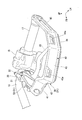
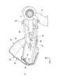
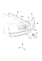
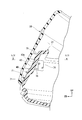
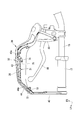
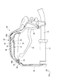
- FIG. 2 is a left side view of a front portion of the motorcycle according to the first embodiment. It is the perspective view which looked at the knuckle guard concerning a first embodiment from the upper front. It is the perspective view which looked at the knuckle guard concerning a 1st embodiment from the rear upper part. It is the perspective view which looked at the 1st protection member concerning a first embodiment from the upper front.
- FIG. 2 is a top view of the knuckle guard according to the first embodiment.
- FIG. 6 is a diagram including a VI-VI cross section of FIG. 5.
- FIG. 7 is a diagram including a section taken along line VII-VII of FIG. 5.
- FIG. 6 is a diagram including a section taken along line VIII-VIII of FIG. 5.
- FIG. 2 is a view including an IX-IX cross section of FIG. 1. It is an explanatory view of arrangement of a knuckle guard concerning a first embodiment.
- FIG. 4 is a rear view of the connecting member according to the first embodiment. It is explanatory drawing of the attachment structure of the 1st protection member and 2nd protection member which concerns on 1st embodiment.
- FIG. 13 is a diagram including a cross section taken along line XIII-XIII of FIG. 5.
- FIG. 14 is a view including a cross section taken along the line XIV-XIV of FIG. 13. It is explanatory drawing of the effect
- FIG. 17 is an explanatory view of the operation of the second protection member following FIG. 16. It is the perspective view which looked at the knuckle guard concerning a second embodiment from the rear upper part. It is a principal part enlarged view including the cross section of the opening adjustment structure of the knuckle guard according to the second embodiment. It is a figure corresponding to Drawing 13 including a section of a knuckle guard concerning a second embodiment.
- FIG. 21 is a view including an XXI-XXI cross section of FIG. 20. It is explanatory drawing of the effect
- FIG. 24 is an explanatory diagram of the operation of the opening adjustment structure following FIG. 23.
- FIG. 25 is an explanatory diagram of the operation of the opening adjustment structure following FIG. 24.
- FIG. 1 shows a motorcycle 1 as an example of a straddle-type vehicle.
- a motorcycle 1 has an engine 2 mounted substantially at the center in the vehicle longitudinal direction.
- the motorcycle may be simply referred to as “vehicle”.
- the motorcycle 1 has the front wheel 3 disposed in front of the engine 2.
- the front wheel 3 is rotatably supported by a pair of left and right front forks 4.
- a top bridge 5 and a bottom bridge 6 are installed in order from the top.
- a fuel tank 7 is provided above the engine 2.
- a steering shaft 8 extending vertically along the axial direction is provided.
- the steering shaft 8 is rotatably supported by a head pipe 10 provided at a front end of the vehicle body frame 9.
- the periphery of the head pipe 10 is covered by a front cowl 11.
- a handle holder 12 is provided on the top surface of the top bridge 5.
- the handle holder 12 includes a lower holder 13 fixed to an upper surface of the top bridge 5 and an upper holder 14 mounted on an upper portion of the lower holder 13.
- the handle 15 is fixed to the handle holder 12 so as to be sandwiched between the lower holder 13 and the upper holder 14.
- the handle 15 is made of a metal pipe.
- the handle 15 is a bar handle that extends in the vehicle width direction in the longitudinal direction.
- Reference numeral 16 in the figure denotes a handle cover that covers the periphery of the handle holder 12.
- a tubular grip 17 made of a resin material is inserted into the outside of the handle 15 in the vehicle width direction (the left side in the figure) and attached to the outside of the handle 15.
- a switch housing 18 (two-dot chain line) accommodating various switches is mounted adjacent to the grip 17 on the handle 15 inside the grip 17 in the vehicle width direction.
- a lever holder 20 for swingably supporting the clutch lever 19 is provided on the handle 15 inside the switch housing 18 (see FIG. 2) in the vehicle width direction. 3, the illustration of the switch housing 18 is omitted.
- reference numeral 21 denotes a side mirror mounting portion.
- a brake lever is swingably supported on the right side of the handle 15.
- the knuckle guard 30 is disposed in front of the grip 17 so as to straddle the grip 17 and the handle 15.
- the knuckle guard 30 is made of resin.
- the knuckle guard 30 covers the front of the occupant's hand when the occupant grips the grip 17.
- the knuckle guard 30 has a U-shape that opens rearward.
- the lever holder 20 also serves as a fastening holder for fixing the inner end 30a of the knuckle guard 30.
- the inner end 30a of the knuckle guard 30 is fastened by a bolt 22, a collar 23, and the like, which constitute a swing shaft of the clutch lever 19 (see FIG. 8).
- the knuckle guard 30 has its inner end 30a fixed to the lever holder 20, extends outward in the vehicle width direction, and straddles the grip 17 in the vehicle width direction.
- Reference numeral 25 in the drawing denotes a weight that protrudes outward from the grip 17 in the vehicle width direction.
- the weight 25 has a function of suppressing vibration of the handle 15.
- reference numeral 28 denotes a bolt for fixing the outer end 30 b of the knuckle guard 30.
- the knuckle guard 30 includes a wind guide portion 35 disposed in front of the grip 17.
- the air guide portion 35 has a communication hole 36 that opens vertically.
- the air guide portion 35 covers the communication hole 36 so that the communication hole 36 is not visible in a front view.
- the knuckle guard 30 has a divided structure.
- the knuckle guard 30 includes a first protection member 31 disposed in front of the grip 17 and a second protection member 32 disposed in front of the first protection member 31.
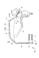
- the first protection member 31 When viewed from above, the first protection member 31 has a U-shape that opens rearward (see FIG. 9). As shown in FIG. 4, the first protection member 31 includes a guard member 39 disposed in front of the grip 17 and a connection member 50 that connects the guard member 39 and the lever holder 20.
- the guard member 39 has an L shape in a top view so as to protect the front and side surfaces of the knuckle portion of the rider (see FIG. 9).
- the guard member 39 includes a front protection part 40 located in front of the grip 17 and a side protection part 45 located on the side of the grip 17.
- the front protection part 40 and the side protection part 45 are integrally formed by the same member.
- the front protection portion 40 has a U-shape that opens rearward (see FIG. 6). As shown in FIG. 9, the front protection part 40 includes a first extension part 41, a second extension part 42, a third extension part 43, and a fourth extension part 44.
- the first extending portion 41 is such that the inner end in the vehicle width direction of the first extending portion 41 is located rearward, and the outer end in the vehicle width direction of the first extending portion 41 is located forward. It is inclined.
- the first extending portion 41 is fixed to the connecting member 50.
- Reference numerals 65 and 66 in the figure denote bolts and nuts for fixing the first extending portion 41 to the fastening member 50, respectively.
- An engagement projection 47 that can engage with the recess 53 a of the front wall 53 of the connecting member 50 is provided on the outer side of the first extension 41 in the vehicle width direction (adjacent to the second extension 42). (See FIG. 9). The engaging projection 47 projects rearward from the rear surface of the outer side of the first extending portion 41 in the vehicle width direction (see FIG. 7).
- the second extending portion 42 extends obliquely outward from the outer end of the first extending portion 41 in the vehicle width direction.
- the second extension 42 connects the first extension 41 and the third extension 43.
- the third extending portion 43 extends outward from the front end of the second extending portion 42 in the vehicle width direction.
- the third extending portion 43 has an insertion hole 43a through which the engaging claw 74 (see FIG. 16) of the second protection member 32 is inserted.
- the insertion hole 43a has a rectangular shape having a length in the vehicle width direction (specifically, the extension direction of the third extension portion 43) (see FIG. 4).
- the insertion hole 43a is disposed at an upper portion of the third extending portion 43 on the inner side in the vehicle width direction (see FIG. 4).
- the fourth extending portion 44 extends obliquely rearward and outward from the outer end of the third extending portion 43 in the vehicle width direction.
- the fourth extending portion 44 has a mounting hole 44a for mounting the second protection member 32 (see FIG. 16).
- the mounting hole 44a has a rectangular shape having a length in the vehicle width direction (specifically, the extending direction of the fourth extending portion 44) (see FIG. 4).
- the mounting hole 44a is disposed above the fourth extension 44 (see FIG. 4).
- the side protection portion 45 extends rearward from the outer end of the fourth extension portion 44 in the vehicle width direction.
- the rear end of the side protection portion 45 is fixed to the outer end of the steering wheel 15 in the vehicle width direction.
- the outer shape of the connecting member 50 has a U-shape that is convex rearward (see FIG. 5).
- the connecting member 50 has a U-shape that opens rearward (see FIG. 8).
- the connection member 50 has an upper wall 51, a lower wall 52, and a front wall 53.
- the upper wall portion 51, the lower wall portion 52, and the front wall portion 53 are integrally formed of the same member.
- the upper wall 51 is disposed above the clutch lever 19.
- the upper wall portion 51 has a plate shape extending in the front-rear direction.
- the lower wall 52 is disposed below the clutch lever 19.
- the lower wall portion 52 has a plate shape extending in the front-rear direction.
- the front wall 53 is arranged in front of the clutch lever 19.
- the front wall 53 connects the front end of the upper wall 51 and the front end of the lower wall 52.
- the front wall portion 53 is positioned such that the inner end in the vehicle width direction of the front wall portion 53 is located rearward along the first extension portion 41 of the front protection portion 40, and the vehicle of the front wall portion 53. It is inclined so that the outer end in the width direction is located forward (see FIG. 9).
- the front wall portion 53 is provided with a concave portion 53a that opens outward in the vehicle width direction.
- a circular through hole 67 through which a shaft of a bolt 65 (see FIG. 9) can be inserted is provided in the front wall 53 of the connecting member 50.
- reference numeral L1 indicates a virtual straight line extending in the front-rear direction
- reference numeral L2 indicates a virtual extension line along the front surface of the front wall 53.
- the angle A1 between the virtual straight line L1 and the virtual extension line L2 (the front surface of the front wall 53) is 90 degrees or less (a sharp angle).
- the second protection member 32 has a larger outer shape than the front protection part 40 of the first protection member 31.
- the second protection member 32 extends in the vehicle width direction along the front protection part 40.
- the upper end of the second protection member 32 is located above the upper end of the first protection member 31.
- the upper edge of the second protection member 32 has an upwardly convex curved shape.
- the lower end of the second protection member 32 is located above the lower end of the front protection part 40.
- the lower edge of the second protection member 32 has an outer shape along the front edge of the front protection portion 40.
- the front surface of the second protective member 32 is inclined such that the upper end of the second protective member 32 is located rearward and the lower end of the second protective member 32 is located forward (see FIG. 6). ).
- a plurality of (for example, three in the embodiment) ribs 70 are provided on the front surface of the second protection member 32.
- the rib 70 extends along the inclined direction of the front surface of the second protection member 32.
- the three ribs 70 are arranged at intervals in the vehicle width direction (specifically, the extending direction of the second protection member 32).
- the second protection member 32 is detachable from the first protection member 31.
- the inner side in the vehicle width direction of the second protection member 32 is attached to the first extending portion 41 of the first protection member 31 by a fastening member 29 such as a bolt.
- the second protection member 32 is attached to the connection member 50 together with the first protection member 31 so as to be detachable from the connection member 50.
- the outer end of the second protection member 32 in the vehicle width direction is attached to the fourth extending portion 44 of the first protection member 31 by a fastening member 72 such as a bolt.
- a fastening member 72 such as a bolt.
- the solid line in FIG. 12 shows an initial state before the second protection member 32 bends.
- a circular through hole 32 a through which the shaft of the bolt 72 can be inserted is provided on the outer side in the vehicle width direction of the second protection member 32.
- the bolt 72 is inserted through the through hole 32a of the second protection member 32 into the mounting hole 44a of the fourth extension 44, and the bolt 72 is projected from the rear surface of the fourth extension 44 (see FIG. 16).
- the second protection member 32 can be fixed to the first protection member 31 by screwing the nut 73 to the protruding portion (male thread portion) of the bolt 72 (see FIG. 16).
- an engagement claw 74 that is inserted into the insertion hole 43 a of the third extending portion 43 of the first protection member 31 is provided at the center of the second protection member 32 in the vehicle width direction. .
- the engagement claw 74 functions as a positioning portion that defines a relative position between the first protection member 31 and the second protection member 32 in the insertion hole 43a.
- the engagement claw 74 protrudes rearward from a rear surface of a central portion of the second protection member 32 in the vehicle width direction.
- the engaging claw 74 has an L-shape extending diagonally left rearward.
- the first protection member 31 and the second protection member 32 form a laminated portion 37 where the protection members overlap.
- the communication hole 36 opens the laminated portion 37 in the vertical direction.
- the stacked portion 37 is a portion where the front protection portion 40 of the first protection member 31 and the lower portion of the second protection member 32 overlap in a front view (see FIG. 2).
- the communication hole 36 is a gap between the front surface of the front protection part 40 and the lower rear surface of the second protection member 32.
- the communication hole 36 is inclined such that the upper end of the opening is located rearward and the lower end of the opening is located forward.
- ⁇ Operation of Knuckle Guard 30> The operation of the knuckle guard 30 according to the embodiment will be described together with a comparative example with reference to FIG.
- the comparative example does not have the communication hole 36 according to the embodiment.
- the lower end of the opening of the communication hole 36 is closed.
- the arrow Wx indicates the flow of the traveling wind of the comparative example
- the arrows W1 and W2 indicate the flow of the traveling wind of the embodiment, respectively.
- the traveling wind flows rearward and upward along the front surface of the second protection member 32, and then enters the rear of the second protection member 32 (see the arrow Wx).
- the pressure difference between the front and the rear of the knuckle guard 30 increases, so that the traveling wind is trapped in the upper part of the second protection member 32.
- the traveling wind flows rearward and upward along the front surface of the second protection member 32 (see arrow W1) and enters the communication hole 36 from the lower end of the opening of the communication hole 36 (see arrow W2).
- the wind flowing along the front surface of the second protection member 32 flows rearward and upward from the upper edge of the second protection member 32.
- the wind that has entered the communication hole 36 enters behind the second protection member 32.
- the pressure difference between the front and the rear of the knuckle guard 30 can be reduced, and the entrainment of the traveling wind can be suppressed.
- the second protection member 32 can expand the communication hole 36 by bending inward in the vehicle width direction along the mounting hole 44a of the first protection member 31.
- FIG. 16 shows an initial state before the second protection member 32 bends.
- the bolt 72 inserted into the through-hole 32 a (see FIG. 12) on the outer side in the vehicle width direction of the second protection member 32 is fixed outside the mounting hole 44 a of the fourth extension 44 in the vehicle width direction. I have.
- the engagement claw 74 is engaged with an opening edge of the insertion hole 43 a of the third extension 43 (hereinafter, referred to as “insertion hole forming portion”).
- the insertion hole forming portion is provided with an engagement protrusion 75 that functions as a positioning portion together with the engagement claw 74.
- the engagement protrusion 75 has a triangular shape that protrudes downward from a rear surface (inclined surface) of the first protection member 31.
- the engagement claw 74 contacts the rear surface of the engagement protrusion 75.
- the engagement claw 74 is engaged with the insertion hole forming portion (engagement projection 75), so that the second protection member 32 moves forward and outward with respect to the first protection member 31 in the vehicle width direction. It is regulated (see FIG. 14).
- reference numeral 71 denotes a positioning projection that defines the front-rear distance between the first protection member 31 and the second protection member 32 in the initial state.
- a plurality of (three in the figure) positioning protrusions 71 are provided at intervals in the vertical direction.
- the positioning projections 71 are provided at intervals in the vehicle width direction.
- a gap between two adjacent positioning projections 71 in the vehicle width direction forms a communication hole 36 (see FIG. 7).
- FIG. 17 shows a state where the second protection member 32 is bent.
- the bolt 72 inserted into the through-hole 32 a (see FIG. 12) on the outer side in the vehicle width direction of the second protection member 32 is fixed inside the mounting hole 44 a of the fourth extension 44 in the vehicle width direction. I have.
- the two-dot chain line in FIG. 12 indicates a state in which the second protection member 32 is bent in a curved shape that is convex forward.
- the outer side in the vehicle width direction of the second protection member 32 is shifted inward in the vehicle width direction, so that the second protection member 32 projects forward. Deflected to have a curved shape.
- the engaging claw 74 is brought into contact with the stepped portion 76 on the front surface of the third extending portion 43 without engaging with the insertion hole forming portion.
- the outer side in the vehicle width direction of the second protection member 32 is fastened. Thereby, the communication hole 36 can be enlarged as compared with the initial state of FIG.
- the knuckle guard 30 in the above-described embodiment includes the air guide portion 35 that is disposed in front of the grip 17 of the handlebar 15 of the vehicle and has the communication hole 36 that opens in the vertical direction.
- the communication hole 36 is covered when viewed from the front.
- the air guide portion 35 covers the communication hole 36 when viewed from the front, and thus has no opening toward the front of the vehicle. Therefore, the knuckle portion and the arm portion of the rider can be protected from the running wind, water, mud, sand, tree branches, and the like by the air guide portion 35. Therefore, it is possible to prevent the wind, mud, gravel and tree branch effects from being lost during traveling.
- the communication hole 36 corrects the negative pressure behind the knuckle guard 30. can do. Therefore, a greater windbreak effect can be obtained with a smaller front projection area.
- the communication hole 36 cannot be seen from the front, a sense of unity of the knuckle guard 30 is created and the design is excellent.
- the knuckle guard 30 includes a first protection member 31 disposed in front of the grip 17 and a second protection member 32 disposed in front of the first protection member 31.
- the laminated member 37 in which the protective members overlap with the member 32 is formed, and the communication hole 36 opens the laminated portion 37 in the up-down direction.
- the knuckle guard 30 has a divided structure, and the communication hole 36 is formed by the laminated portion 37 of the divided parts (the first protection member 31 and the second protection member 32). And the knuckle guard 30 is easily formed.
- the first protection member 31 has a mounting hole 44a for mounting the second protection member 32, the mounting hole 44a is a long hole having a length in the vehicle width direction, and the second protection member 32 is provided in the mounting hole 44a.
- the communication hole 36 can be expanded by bending inward in the vehicle width direction along with the following, and the following effects can be obtained. According to this configuration, by bending the second protection member 32 inward in the vehicle width direction and fixing the second protection member 32 inside the mounting hole 44a of the first protection member 31 in the vehicle width direction, the communication hole 36 (gap) of the laminated portion 37 is formed. Can be adjusted to adjust the air flow toward the rear of the knuckle guard 30 (air flow for correcting the negative pressure behind the knuckle guard 30). Therefore, it is easy to adjust the windproof range and the air volume behind the knuckle guard 30 according to the rider's preference, taking into account the traveling conditions such as the traveling speed and the air temperature (including the ambient temperature at hand).
- the first protection member 31 has an insertion hole 43a which is a long hole having a length in the vehicle width direction, and defines a position between the first protection member 31 and the second protection member 32 in the insertion hole 43a.
- the provision of the positioning portion 74 has the following effects. According to this configuration, the relative position between the first protection member 31 and the second protection member 32 can be defined.
- the second protection member 32 is provided with an engagement claw 74 that can be inserted into the insertion hole 43 a of the first protection member 31 as a positioning portion 74.
- the engagement claw 74 engages with the opening edge of the insertion hole 43a of the first protection member 31,
- the engagement claw 74 abuts on the stepped portion 76 on the front surface of the first protection member 31 to provide the following effects. According to this configuration, in each of the initial state and the curved state of the second protection member 32, the relative position between the first protection member 31 and the second protection member 32 can be defined.
- the second protective member 32 has the following effects by being detachable from the first protective member 31. According to this configuration, by removing the second protection member 32 from the first protection member 31, it is possible to use only the first protection member 31. For example, during long-distance travel or off-road travel, the vehicle travels with the second protective member 32 attached to the first protective member 31. For example, the vehicle travels only with the first protection member 31 during low-speed traveling or on-road traveling in an urban area or the like. For example, when the temperature is high or low and the temperature is low, the vehicle travels with the second protection member 32 attached to the first protection member 31. For example, when the temperature is high, the vehicle travels only with the first protection member 31.
- the specifications of the knuckle guard 30 can be changed according to the conditions in this way, the degree of freedom in changing the specifications is improved.
- the specification can be changed by adding only a part of the knuckle guard 30 without replacing the entire knuckle guard 30 with another part, the part cost is reduced.
- the attachment hole 44a can function as a wind guide hole.
- the opening adjustment structure 170 protrudes rearward from the second protection member 32, and has an elastic protrusion 173 that is elastically deformable and a length provided in the first protection member 31 and having a length in the vehicle width direction.
- a mounting hole 44a (see FIG. 19) for mounting the elastic projection 173, and a fastening member for fastening the first protection member 31 and the second protection member 32 by elastically deforming the elastic projection 173.
- 172 a wind-proof convex portion 171 provided between the first protection member 31 and the second protection member 32 and blocking at least a part of the wind that has entered the communication hole 36, an engagement claw 74, and an insertion hole 43a.
- a plurality of (for example, two in this embodiment) step portions 176 and 177 (first step portion 176 and second step portion 177) provided on the front surface of first protection member 31; (See FIG. 21).
- the elastic projection 173 has a cylindrical shape protruding rearward from the outer end of the second protection member 32 in the vehicle width direction.
- the elastic projection 173 is a blind nut made of rubber.
- the elastic projection 173 is attached to the fourth extension 44 of the first protection member 31 by a fastening member 172 such as a bolt.
- the elastic convex portion 173 projects obliquely rearward and inward from the fourth extending portion 44 through the mounting hole 44a (see FIG. 23).
- the mounting hole 44a is provided on the outer side of the first protection member 31 in the vehicle width direction (the fourth extending portion 44).
- the elastic convex portion 173 is held in the mounting hole 44a from the front of the fourth extending portion 44.
- the first protection member 31 and the second protection member 32 can be fastened by elastically deforming the elastic projection 173 by a bolt tightening operation from one side (vehicle front side).
- the elastic projection 173 before elastic deformation is indicated by a two-dot chain line
- the elastic projection 173 after elastic deformation is indicated by a solid line.
- Reference numeral 179 in the figure denotes a washer provided between the first protection member 31 (the fourth extension portion 44) and the second protection member 32 (the portion of the elastic projection 173 on the bolt head side).
- the windproof projection 171 protrudes rearward from the second protection member 32.
- the windproof protrusion 171 extends continuously in the vehicle width direction from the vehicle width direction outer portion of the second protection member 32 to the vehicle width direction inner portion.
- the windproof convex portion 171 extends from the portion of the second protection member 32 facing the fourth extension portion 44 of the first protection member 31 (outside portion in the vehicle width direction) to the portion facing the second extension portion 42 (vehicle). (The widthwise inner part).
- the first step portion 176 is provided on the front surface of the third extending portion 43 of the first protection member 31.
- the second step 177 is provided on the front surface of the third extension 43 of the first protection member 31 in front of the first step 176.
- the first step portion 176 and the second step portion 177 have a stepped shape.
- the windproof convex portion 171 contacts the front surface of the first protective member 31 in a state where the elastic convex portion 173 is located at the outer end of the mounting hole 44a in the vehicle width direction (initial state), and thus the communication is established.
- the hole 36 is closed.
- the traveling wind flows rearward and upward along the front surface of the second protection member 32 (see the arrow W3).
- the traveling wind does not enter the communication hole 36 from the lower end of the communication hole 36 as in the first embodiment (see the arrow W2 in FIG. 15).
- the traveling wind flows rearward and upward along the front surface of the second protection member 32, and then enters behind the second protection member 32.
- the communication hole 36 can be closed in the initial state, and the air can be prevented from passing through the communication hole 36, so that adjustments can be made in accordance with preferences and situations.
- the opening adjustment structure 170 can adjust the opening area of the communication hole 36 by bending the second protection member 32 inward in the vehicle width direction along the mounting hole 44a of the first protection member 31.
- FIG. 23 shows an initial state before the second protection member 32 bends.
- the elastic projection 173 is elastically deformed by the bolt 172 inserted into the through hole 32a (see FIG. 19) on the outer side in the vehicle width direction of the second protection member 32.
- the elastic projection 173 is located at the outer end in the vehicle width direction of the mounting hole 44 a of the fourth extension 44.
- the engagement claw 74 is engaged with the engagement protrusion 75 at one edge in the vehicle width direction of the insertion hole 43 a of the third extension 43.
- the communication hole 36 is closed by the contact of the windproof projection 171 with the front surface of the first protection member 31 (see FIG. 22).
- FIG. 24 shows a first curved state in which the second protective member 32 is bent in a curved shape that is convex forward.
- the vehicle width of the second protection member 32 is kept in a state where the inner side in the vehicle width direction of the second protection member 32 is fastened and the elastic projection 173 is elastically deformed in the mounting hole 44a (for example, in an initial state).
- the second protection member 32 is bent so as to have a curved shape that is convex forward.
- the elastic convex portion 173 is located at the center of the mounting hole 44a of the fourth extending portion 44 in the vehicle width direction.
- the engaging claw 74 is in contact with the first step portion 176 on the front surface of the third extending portion 43 without engaging with the engaging protrusion 75. Thereby, the communication hole 36 can be opened (enlarged) with respect to the initial state of FIG.
- FIG. 25 shows a second curved state in which the second protective member 32 is bent in a curved shape that is convex forward of the first curved state.
- the second protection member 32 in a state where the inner portion in the vehicle width direction of the second protection member 32 is fastened, the second protection member 32 is kept in a state (for example, a first curved state) in which the elastic projection 173 is elastically deformed in the mounting hole 44a.
- the second protection member 32 is further bent so as to have a curved shape that is convex forward.
- the elastic convex portion 173 is located at the inner end in the vehicle width direction of the mounting hole 44 a of the fourth extending portion 44.
- the engaging claw 74 In the second curved state, the engaging claw 74 is in contact with the second step portion 177 on the front surface of the third extending portion 43 without engaging with the engaging protrusion 75. Thereby, the communication hole 36 can be enlarged more than the second curved state in FIG. Note that the engagement claw 74 does not necessarily need to contact the second step portion 177. As long as the elastic convex portion 173 can be supported in the mounting hole 44a, the engaging claw 74 may be in a state of floating from the second step portion 177.
- the knuckle guard 130 includes the opening adjustment structure 170 that adjusts the opening area of the communication hole 36, and the opening adjustment structure 170 projects rearward from the second protection member 32, and is elastically deformed.
- a possible elastic convex portion 173, a long hole provided in the first protection member 31 and having a length in the vehicle width direction, and a mounting hole 44 a for mounting the elastic convex portion 173, and the elastic convex portion 173 are elastically deformed.
- a fastening member 172 for fastening the first protection member 31 and the second protection member 32.
- the second protection member 32 is bent inward in the vehicle width direction, and the elastic protrusion 173 is elastically deformed and fixed inside the mounting hole 44a of the first protection member 31 in the vehicle width direction.
- the communication hole 36 can be enlarged, and the amount of air flowing toward the rear of the knuckle guard 130 through the communication hole 36 can be increased.
- the communication hole 36 can be reduced, and the communication hole 36 can be reduced.
- the amount of air flowing rearward can be reduced. For this reason, it is easy to adjust the windproof range and the air volume behind the knuckle guard 130 according to the rider's preference in consideration of the traveling conditions such as the traveling speed and the air temperature (including the ambient temperature at hand).
- the opening adjusting structure 170 is provided between the first protection member 31 and the second protection member 32, and further includes a windproof convex portion 171 that blocks at least a part of the wind that has entered the communication hole 36, and has the following effects. To play. According to this configuration, at least a part of the wind that has entered the communication hole 36 is blocked by the windproof convex portion 171, so that the amount of air flowing rearward of the knuckle guard 130 through the communication hole 36 can be reduced.
- the mounting hole 44a is provided on the outer side of the first protection member 31 in the vehicle width direction, and the windproof convex portion 171 protrudes rearward from the second protection member 32 and extends from the outer side of the second protection member 32 in the vehicle width direction.
- the following effects are obtained by extending continuously in the vehicle width direction over the inner portion in the vehicle width direction. According to this configuration, it is easier to reduce the amount of air flowing toward the rear of the knuckle guard 130 through the communication hole 36 as compared with a case where a plurality of the windproof protrusions 171 are arranged at intervals in the vehicle width direction.
- the second protection member 32 when the second protection member 32 is detachable from the first protection member 31, the second protection member 32 is moved to the first protection member 31 in comparison with a configuration in which the windproof projection 171 protrudes forward from the first protection member 31.
- the appearance of the first protection member 31 when removed from the protection member 31 can be enhanced.
- the opening adjusting structure 170 closes the communication hole 36 by the windproof convex portion 171 abutting on the front surface of the first protective member 31 in a state where the elastic convex portion 173 is located at the outer end in the vehicle width direction of the mounting hole 44a.
- the communication hole 36 is closed by elastically deforming the elastic projection 173 and fixing the second protection member 32 at the outer end in the vehicle width direction of the mounting hole 44a of the first protection member 31.
- air can be prevented from passing through the communication hole 36. Therefore, it is possible to make adjustments in accordance with preferences and circumstances.
- the wind protection convex part 171 contacts the front surface of the first protection member 31, it is possible to suppress the play between the first protection member 31 and the second protection member 32.
- the opening adjusting structure 170 has an L-shaped engaging claw 74 extending obliquely rearward and outward from the rear surface of the second protection member 32, and a length provided in the first protection member 31 and having a length in the vehicle width direction.
- the insertion claw 74 is an insertion hole 43a through which the engagement claw 74 can be inserted, and the engagement claw 74 in an initial state before the second protection member 32 is bent at one edge of the insertion hole 43a in the vehicle width direction.
- a first curved state in which the second protrusion is a stepped portion provided on the front surface of the first protection member 31, wherein the second protection member 32 is bent in a convexly convex shape.
- the a second step portion 177 capable of contacting, by further comprising the following effects.
- the relative position between the first protection member 31 and the second protection member 32 can be defined in each of the initial state, the first bending state, and the second bending state of the second protection member 32.
- the amount of air flowing toward the rear of the knuckle guard 130 through the communication hole 36 can be adjusted in three stages of the initial state, the first bending state, and the second bending state of the second protection member 32.
- the windproof protrusion 171 protrudes rearward from the second protection member 32
- the present invention is not limited to this.
- the windproof projection 171 may protrude forward from the first protection member 31. That is, the windproof protrusion 171 may be provided between the first protection member 31 and the second protection member 32.
- the windproof convex portion 171 continuously extends in the vehicle width direction from the vehicle width direction outer portion to the vehicle width direction inner portion of the second protection member 32.
- a plurality of windproof convex portions 171 may be arranged at intervals in the vehicle width direction.
- the windproof projection 171 may have a function of blocking at least a part of the wind that has entered the communication hole 36.
- the opening adjustment structure 170 includes the two step portions 176 and 177 .
- the present invention is not limited thereto.
- the number of step portions may be only one, or may be three or more.
- the communication hole 36 has been described with an example in which the entirety of the stacked portion 37 where the first protection member 31 and the second protection member 32 overlap in the front view is opened in the vertical direction. Not exclusively.
- the communication hole 36 may open a part of the laminated portion 37 in the up-down direction.
- the communication hole 36 may open at least a part of the laminated portion 37 in the up-down direction.
- the knuckle guard 30 has a divided structure, and the divided parts (the first protection member 31 and the second protection member 32) have been described.
- the invention is not limited thereto.
- the knuckle guard 30 may be provided with only one protection member without having a divided structure.
- the second protection member 32 is detachable from the first protection member 31.
- the present invention is not limited to this.
- the second protection member 32 may be integrated with the first protection member 31 so as not to be detachable from the first protection member 31.
- the front protection portion 40 and the side protection portion 45 are integrally formed of the same member, but the invention is not limited thereto.
- the front protection part 40 and the side protection part 45 may be formed of different members, respectively.
- the side protection part 45 may be fastened to the front protection part 40 by a bolt or the like.
- the handle 15 to which the knuckle guard 30 was attached was a bar handle, but the present invention is not limited to this.
- the handle 15 to which the knuckle guard 30 is attached may be a so-called separate handle that separates left and right.
- a knuckle guard 30 may be attached after inserting a weight through the pipe-shaped portion.
- the saddle-ride type vehicle includes all vehicles in which a driver rides across a vehicle body, and includes only a motorcycle (including a motor-driven bicycle and a scooter type vehicle). However, a three-wheeled vehicle (including a front two-wheeled vehicle and a front two-wheeled vehicle in addition to a front one-wheeled vehicle and a rear two-wheeled vehicle) or a four-wheeled vehicle is also included.
- the configuration in the above embodiment is an example of the present invention, and various changes can be made without departing from the gist of the present invention, such as replacing the component of the embodiment with a known component.
Landscapes
- Engineering & Computer Science (AREA)
- Mechanical Engineering (AREA)
- Automatic Cycles, And Cycles In General (AREA)
- Body Structure For Vehicles (AREA)
- Professional, Industrial, Or Sporting Protective Garments (AREA)
Abstract
Priority Applications (4)
| Application Number | Priority Date | Filing Date | Title |
|---|---|---|---|
| US17/270,061 US12151761B2 (en) | 2018-09-28 | 2019-04-01 | Knuckle guard |
| DE112019004872.4T DE112019004872B4 (de) | 2018-09-28 | 2019-04-01 | Knöchelschutz |
| JP2020547928A JP7100147B2 (ja) | 2018-09-28 | 2019-04-01 | ナックルガード |
| BR112021003954-6A BR112021003954B1 (pt) | 2018-09-28 | 2019-04-01 | Protetor de articulação |
Applications Claiming Priority (2)
| Application Number | Priority Date | Filing Date | Title |
|---|---|---|---|
| PCT/JP2018/036397 WO2020065951A1 (fr) | 2018-09-28 | 2018-09-28 | Coquille |
| JPPCT/JP2018/036397 | 2018-09-28 |
Publications (1)
| Publication Number | Publication Date |
|---|---|
| WO2020066079A1 true WO2020066079A1 (fr) | 2020-04-02 |
Family
ID=69949772
Family Applications (2)
| Application Number | Title | Priority Date | Filing Date |
|---|---|---|---|
| PCT/JP2018/036397 Ceased WO2020065951A1 (fr) | 2018-09-28 | 2018-09-28 | Coquille |
| PCT/JP2019/014432 Ceased WO2020066079A1 (fr) | 2018-09-28 | 2019-04-01 | Protège-mains |
Family Applications Before (1)
| Application Number | Title | Priority Date | Filing Date |
|---|---|---|---|
| PCT/JP2018/036397 Ceased WO2020065951A1 (fr) | 2018-09-28 | 2018-09-28 | Coquille |
Country Status (5)
| Country | Link |
|---|---|
| US (1) | US12151761B2 (fr) |
| JP (1) | JP7100147B2 (fr) |
| BR (1) | BR112021002761A2 (fr) |
| DE (1) | DE112019004872B4 (fr) |
| WO (2) | WO2020065951A1 (fr) |
Citations (4)
| Publication number | Priority date | Publication date | Assignee | Title |
|---|---|---|---|---|
| JPS6437785U (fr) * | 1987-09-02 | 1989-03-07 | ||
| JPH10218059A (ja) * | 1997-02-07 | 1998-08-18 | Yamaha Motor Co Ltd | スクータ型自動二輪車 |
| US20160031510A1 (en) * | 2014-08-01 | 2016-02-04 | Andrew Serbinski | Multifuntional hand guard |
| US20160311490A1 (en) * | 2015-04-26 | 2016-10-27 | Paul Degarate | Integrated Hand Guard System |
Family Cites Families (4)
| Publication number | Priority date | Publication date | Assignee | Title |
|---|---|---|---|---|
| JPS6437785A (en) | 1987-07-31 | 1989-02-08 | Matsushita Electric Industrial Co Ltd | Recording and reproducing device |
| US20080203762A1 (en) | 2007-02-23 | 2008-08-28 | Randall Shimanski | Handguard apparatus and methods |
| WO2012127070A1 (fr) * | 2011-03-18 | 2012-09-27 | Gimenez Belmonte Joana | Moufle intégré dans un protège-main pour guidon de motocycles |
| JP6003477B2 (ja) | 2012-09-27 | 2016-10-05 | スズキ株式会社 | 二輪車のハンドルカバー装置 |
-
2018
- 2018-09-28 WO PCT/JP2018/036397 patent/WO2020065951A1/fr not_active Ceased
- 2018-09-28 BR BR112021002761-0A patent/BR112021002761A2/pt not_active Application Discontinuation
-
2019
- 2019-04-01 US US17/270,061 patent/US12151761B2/en active Active
- 2019-04-01 WO PCT/JP2019/014432 patent/WO2020066079A1/fr not_active Ceased
- 2019-04-01 DE DE112019004872.4T patent/DE112019004872B4/de active Active
- 2019-04-01 JP JP2020547928A patent/JP7100147B2/ja active Active
Patent Citations (4)
| Publication number | Priority date | Publication date | Assignee | Title |
|---|---|---|---|---|
| JPS6437785U (fr) * | 1987-09-02 | 1989-03-07 | ||
| JPH10218059A (ja) * | 1997-02-07 | 1998-08-18 | Yamaha Motor Co Ltd | スクータ型自動二輪車 |
| US20160031510A1 (en) * | 2014-08-01 | 2016-02-04 | Andrew Serbinski | Multifuntional hand guard |
| US20160311490A1 (en) * | 2015-04-26 | 2016-10-27 | Paul Degarate | Integrated Hand Guard System |
Also Published As
| Publication number | Publication date |
|---|---|
| DE112019004872T5 (de) | 2021-06-10 |
| WO2020065951A1 (fr) | 2020-04-02 |
| JP7100147B2 (ja) | 2022-07-12 |
| BR112021002761A2 (pt) | 2021-05-11 |
| DE112019004872B4 (de) | 2024-07-25 |
| JPWO2020066079A1 (ja) | 2021-08-30 |
| BR112021003954A2 (pt) | 2021-05-25 |
| US12151761B2 (en) | 2024-11-26 |
| US20210323627A1 (en) | 2021-10-21 |
Similar Documents
| Publication | Publication Date | Title |
|---|---|---|
| US8783399B2 (en) | Saddle-riding type vehicle including multi-part shroud | |
| US8899668B2 (en) | Air guide structure for saddle type vehicle | |
| JP5555586B2 (ja) | 鞍乗り型車両のフェアリング構造 | |
| US10450026B2 (en) | Air guide structure of a saddle-type vehicle | |
| JP5328544B2 (ja) | 鞍乗り型車両におけるメータカバー構造 | |
| CN103707964A (zh) | 摩托车 | |
| JP2011148451A (ja) | 鞍乗り型車両の前部構造 | |
| WO2009098925A1 (fr) | Véhicule de type à selle | |
| JP7621322B2 (ja) | 車両 | |
| JP6766125B2 (ja) | 鞍乗り型車両のタンクカバー構造 | |
| JP7191907B2 (ja) | 鞍乗り型車両 | |
| US11077904B2 (en) | Knuckle guard | |
| JP4322289B2 (ja) | ウインドスクリーンの取付構造 | |
| WO2020066079A1 (fr) | Protège-mains | |
| JP2017165387A (ja) | 車両のラジエータシュラウド | |
| JP7528654B2 (ja) | フロントカウル | |
| JP7692970B2 (ja) | 鞍乗型車両 | |
| US10597103B2 (en) | Saddle-type vehicle | |
| JP7171661B2 (ja) | 鞍乗り型車両 | |
| JP7245630B2 (ja) | 鞍乗型車両及びメータバイザ | |
| JP7456981B2 (ja) | 鞍乗り型車両 | |
| JP2014028542A (ja) | 鞍乗型車両 | |
| JP2025185415A (ja) | 鞍乗型車両 | |
| JP2025136687A (ja) | 鞍乗型車両 | |
| CN112829861A (zh) | 后挡板 |
Legal Events
| Date | Code | Title | Description |
|---|---|---|---|
| 121 | Ep: the epo has been informed by wipo that ep was designated in this application |
Ref document number: 19867101 Country of ref document: EP Kind code of ref document: A1 |
|
| ENP | Entry into the national phase |
Ref document number: 2020547928 Country of ref document: JP Kind code of ref document: A |
|
| REG | Reference to national code |
Ref country code: BR Ref legal event code: B01A Ref document number: 112021003954 Country of ref document: BR |
|
| ENP | Entry into the national phase |
Ref document number: 112021003954 Country of ref document: BR Kind code of ref document: A2 Effective date: 20210302 |
|
| 122 | Ep: pct application non-entry in european phase |
Ref document number: 19867101 Country of ref document: EP Kind code of ref document: A1 |