WO2020067060A1 - リンク作動装置 - Google Patents
リンク作動装置 Download PDFInfo
- Publication number
- WO2020067060A1 WO2020067060A1 PCT/JP2019/037372 JP2019037372W WO2020067060A1 WO 2020067060 A1 WO2020067060 A1 WO 2020067060A1 JP 2019037372 W JP2019037372 W JP 2019037372W WO 2020067060 A1 WO2020067060 A1 WO 2020067060A1
- Authority
- WO
- WIPO (PCT)
- Prior art keywords
- link
- main body
- abnormality
- actuating device
- device main
- Prior art date
- Legal status (The legal status is an assumption and is not a legal conclusion. Google has not performed a legal analysis and makes no representation as to the accuracy of the status listed.)
- Ceased
Links
Images






Classifications
-
- B—PERFORMING OPERATIONS; TRANSPORTING
- B25—HAND TOOLS; PORTABLE POWER-DRIVEN TOOLS; MANIPULATORS
- B25J—MANIPULATORS; CHAMBERS PROVIDED WITH MANIPULATION DEVICES
- B25J9/00—Program-controlled manipulators
- B25J9/003—Program-controlled manipulators having parallel kinematics
- B25J9/0045—Program-controlled manipulators having parallel kinematics with kinematics chains having a rotary joint at the base
- B25J9/0048—Program-controlled manipulators having parallel kinematics with kinematics chains having a rotary joint at the base with kinematics chains of the type rotary-rotary-rotary
-
- B—PERFORMING OPERATIONS; TRANSPORTING
- B25—HAND TOOLS; PORTABLE POWER-DRIVEN TOOLS; MANIPULATORS
- B25J—MANIPULATORS; CHAMBERS PROVIDED WITH MANIPULATION DEVICES
- B25J17/00—Joints
- B25J17/02—Wrist joints
- B25J17/0258—Two-dimensional joints
- B25J17/0266—Two-dimensional joints comprising more than two actuating or connecting rods
-
- B—PERFORMING OPERATIONS; TRANSPORTING
- B25—HAND TOOLS; PORTABLE POWER-DRIVEN TOOLS; MANIPULATORS
- B25J—MANIPULATORS; CHAMBERS PROVIDED WITH MANIPULATION DEVICES
- B25J9/00—Program-controlled manipulators
- B25J9/16—Program controls
- B25J9/1615—Program controls characterised by special kind of manipulator, e.g. planar, scara, gantry, cantilever, space, closed chain, passive/active joints and tendon driven manipulators
- B25J9/1623—Parallel manipulator, Stewart platform, links are attached to a common base and to a common platform, plate which is moved parallel to the base
-
- B—PERFORMING OPERATIONS; TRANSPORTING
- B25—HAND TOOLS; PORTABLE POWER-DRIVEN TOOLS; MANIPULATORS
- B25J—MANIPULATORS; CHAMBERS PROVIDED WITH MANIPULATION DEVICES
- B25J9/00—Program-controlled manipulators
- B25J9/16—Program controls
- B25J9/1674—Program controls characterised by safety, monitoring, diagnostic
-
- F—MECHANICAL ENGINEERING; LIGHTING; HEATING; WEAPONS; BLASTING
- F16—ENGINEERING ELEMENTS AND UNITS; GENERAL MEASURES FOR PRODUCING AND MAINTAINING EFFECTIVE FUNCTIONING OF MACHINES OR INSTALLATIONS; THERMAL INSULATION IN GENERAL
- F16C—SHAFTS; FLEXIBLE SHAFTS; ELEMENTS OR CRANKSHAFT MECHANISMS; ROTARY BODIES OTHER THAN GEARING ELEMENTS; BEARINGS
- F16C41/00—Other accessories, e.g. devices integrated in the bearing not relating to the bearing function as such
-
- F—MECHANICAL ENGINEERING; LIGHTING; HEATING; WEAPONS; BLASTING
- F16—ENGINEERING ELEMENTS AND UNITS; GENERAL MEASURES FOR PRODUCING AND MAINTAINING EFFECTIVE FUNCTIONING OF MACHINES OR INSTALLATIONS; THERMAL INSULATION IN GENERAL
- F16H—GEARING
- F16H21/00—Gearings comprising primarily only links or levers, with or without slides
- F16H21/46—Gearings comprising primarily only links or levers, with or without slides with movements in three dimensions [3D]
-
- G—PHYSICS
- G05—CONTROLLING; REGULATING
- G05B—CONTROL OR REGULATING SYSTEMS IN GENERAL; FUNCTIONAL ELEMENTS OF SUCH SYSTEMS; MONITORING OR TESTING ARRANGEMENTS FOR SUCH SYSTEMS OR ELEMENTS
- G05B19/00—Program-control systems
- G05B19/02—Program-control systems electric
- G05B19/04—Program control other than numerical control, i.e. in sequence controllers or logic controllers
- G05B19/042—Program control other than numerical control, i.e. in sequence controllers or logic controllers using digital processors
- G05B19/0426—Programming the control sequence
-
- G—PHYSICS
- G05—CONTROLLING; REGULATING
- G05B—CONTROL OR REGULATING SYSTEMS IN GENERAL; FUNCTIONAL ELEMENTS OF SUCH SYSTEMS; MONITORING OR TESTING ARRANGEMENTS FOR SUCH SYSTEMS OR ELEMENTS
- G05B23/00—Testing or monitoring of control systems or parts thereof
- G05B23/02—Electric testing or monitoring
- G05B23/0205—Electric testing or monitoring by means of a monitoring system capable of detecting and responding to faults
- G05B23/0218—Electric testing or monitoring by means of a monitoring system capable of detecting and responding to faults characterised by the fault detection method dealing with either existing or incipient faults
- G05B23/0224—Process history based detection method, e.g. whereby history implies the availability of large amounts of data
- G05B23/0227—Qualitative history assessment, whereby the type of data acted upon, e.g. waveforms, images or patterns, is not relevant, e.g. rule based assessment; if-then decisions
- G05B23/0235—Qualitative history assessment, whereby the type of data acted upon, e.g. waveforms, images or patterns, is not relevant, e.g. rule based assessment; if-then decisions based on a comparison with predetermined threshold or range, e.g. "classical methods", carried out during normal operation; threshold adaptation or choice; when or how to compare with the threshold
Definitions
- the present invention relates to a link actuating device used for a device requiring a precise and wide operating range, such as a medical device or an industrial device, and more particularly to a technique for judging an abnormality of a rotating pair part thereof.
- the link actuating device disclosed in Patent Literature 1 includes a parallel link mechanism in which the attitude of the link hub on the distal end side is connected to the link hub on the proximal end side via three or more sets of link mechanisms so that the attitude can be changed. At least two sets of link mechanisms among the link mechanisms include an attitude control drive source for arbitrarily changing the attitude of the distal link hub with respect to the proximal link hub.
- the link actuating device having the above configuration, it is possible to improve positioning accuracy and rigidity by inserting a shim between the bearings provided on each rotating pair at the time of assembling, applying a preload, and reducing the play of the rotating pair. it can. Further, by combining bearings (front alignment (DB), back alignment (DF), etc.), the rigidity of the rotating pair can be improved, and the positioning accuracy and rigidity of the device can be improved.
- bearings front alignment (DB), back alignment (DF), etc.
- the rigidity of the rotating pair can be improved, and the positioning accuracy and rigidity of the device can be improved.
- DB front alignment
- DF back alignment
- the rigidity of the rotating pair can be improved, and the positioning accuracy and rigidity of the device can be improved.
- desired positioning accuracy and rigidity cannot be obtained due to forgetting to insert or overlapping the shim, a mistake in the combination of the bearings, and the like.
- An object of the present invention is to solve the above-mentioned problems, and an object of the present invention is to easily detect a link operation device main body assembly error and a decrease in rigidity and positioning accuracy due to long-term operation without disassembling and continuing operation. Is to provide a link actuating device that can do this.
- the link operating device of the present invention will be described with reference numerals used in the embodiments.
- the link actuating device according to the present invention is a portion for connecting the link hub 13 on the distal end side to the link hub 12 on the proximal end side via a link mechanism 14 such that the attitude of the link hub 13 can be changed.
- a parallel link mechanism 10 having a pair of rotating pairs 31 to 34, and a drive source 11 (11-1 to 11-3) for controlling the attitude, which arbitrarily changes the attitude of the link hub 13 on the distal end side with respect to the link mechanism 14.
- the control device 2 measures a predetermined state value which is affected by an abnormality of the paired rotating parts 31 to 34 in the link operating device main body 1 composed of the parallel link mechanism 10 and the attitude control drive source 11.
- An abnormality detecting means 4 having a measuring section 5 and a judging section 6 for judging from the measurement result of the measuring section 5 that the link actuating device main body 1 has an abnormality in any of the rotating pair parts 31 to 34 is provided. Prepare.
- the control device 2 includes a measuring unit 5 that measures some state value of the link operating device main body 1 that is affected by the abnormality of the rotating pair units 31 to 34, and a measurement result of the measuring unit 5. And a determination unit 7 for determining that the link operating device main body 1 has an abnormality in any of the paired rotating parts 31 to 34. For this reason, the assembly errors of the rotating paired parts 31 to 34 constituted by the bearing 23 of the link operating device main body 1 and its peripheral parts and the reduction in rigidity and positioning accuracy due to long-term operation are not disassembled and the operation is continued. However, it can be easily detected.
- the measuring unit 5 measures the rigidity of the link actuating device main body 1, and the determining unit 6 determines the abnormality according to a rule determined from a value measured by the measuring unit 5.
- the rigidity of the link actuating device main body 1 is such that the posture of the link actuating device main body 1 does not easily change, and the rigidity of each of the pair of rotations 31 to 34 makes it difficult to rotate. Appears as a stiffness of 1.
- the set rules may be set arbitrarily.For example, the current measurement value is compared with a reference value defined on the design or a reference value determined from a measurement value collected during normal operation, and the reference value is allowed. If it is within the range, it may be determined that there is an abnormality. The determination within the allowable range may be determined based on whether or not a threshold value serving as a reference value is exceeded. Further, it may be determined whether or not an abnormality is present by a plurality of measurements and comparisons.
- the measuring unit 5 may measure the natural frequency of the link operating device body 1 and estimate the rigidity from the natural frequency.
- the rigidity of the link operating device main body 1 is related to the natural frequency, and the rigidity decreases as the natural frequency decreases. Therefore, by using the measured value of the natural frequency of the link operating device main body 1, it is possible to determine the abnormality of the link operating device main body 1.
- the measured value of rigidity it can be confirmed by inspection by an operation test immediately after assembly or measurement during operation, and therefore, shipment of defective products such as operation failure can be prevented.
- the measuring unit 5 measures the torque of the attitude control drive source 11 and estimates the stiffness of the link actuating device body 1 from the measured torque. You may make it.
- the rigidity of the rotating paired parts 31 to 34 that is, the difficulty in turning, appears as the torque of the attitude control drive source 11. Therefore, the torque of the attitude control drive source 11 can be measured, and the rigidity of the link operating device main body 1 can be estimated from the measured torque. Thereby, an assembly error can be detected, and the checking operation can be simplified. In addition, since it can be confirmed by inspection by an operation test immediately after assembling or measurement during operation, it is possible to prevent shipment of defective products such as operation failure.
- the determination unit 6 stores the state values in a plurality of types of postures of the link operating device main body 1 when the respective rotating pair portions 31 to 34 of the link operating device main body 1 are normal.
- the determination unit 6 compares a value determined from the stored state values in the plurality of types of postures with a state value measured by the measurement unit 5 to determine the abnormality. May be performed.
- the control device 2 is provided with an abnormality determination operation command section 3c for driving the attitude control drive source 11 so that the link operation device main body 1 has a predetermined attitude for abnormality determination. It may be.
- an operation for abnormality determination after assembling of the link operating device or before each operation start according to a command of the abnormality determining operation instruction unit 3c, not only initial failure such as an assembly error but also wear is achieved. For example, fluctuations during long-term use due to such factors can be reliably detected.
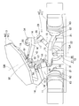
- FIG. 2 is an explanatory diagram in which a perspective view of a link operating device main body in the link operating device according to the first embodiment of the present invention is combined with a block diagram of a control device. It is a perspective view of the attitude
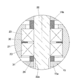
- FIG. 7 is an enlarged sectional view showing a part of FIG. 6 in an enlarged manner.
- FIG. 8 is an enlarged cutaway plan view showing a part VIII of FIG. 7 in a further enlarged manner.
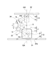
- FIG. 3 is a model diagram showing a parallel link mechanism of the link operating device body in a straight line. It is a flowchart which shows an example of abnormality detection in the link operation device. It is a flowchart which shows the other example of abnormality detection in the link operation device.
- This link actuating device controls a link actuating device main body 1 composed of a parallel link mechanism 10 and a drive source 11 (11-1, 11-2, 11-3) for controlling the attitude of the parallel link mechanism 10. And a control device 2 that performs the control.
- the parallel link mechanism 10 has a link hub 13 on the distal end side connected to a link hub 12 on the proximal end side via three sets of link mechanisms 14 so as to be changeable in posture.
- the number of link mechanisms 14 may be four or more.
- the link mechanism 14 is composed of a proximal end link member 15, a distal end link member 16, and a center link member 17, and includes four rotating pairs 31 to 34. It forms a four-bar linkage mechanism.
- the proximal and distal end link members 15 and 16 are L-shaped, and have one end rotatably connected to the proximal link hub 12 and the distal link hub 13, respectively.
- the center link member 17 has the other ends of the end link members 15 and 16 on the base end side and the distal end side rotatably connected to both ends, respectively.
- the parallel link mechanism 10 has a structure in which two spherical link mechanisms are combined.
- the parallel link mechanism 10 has a pair of rotating pairs 31 and 32 of the link hubs 12 and 13 and end link members 15 and 16, and end link members 15 and 16.
- the central axes O1 and O2 of the rotating paired parts 33 and 34 of the central link member 17 intersect at the respective spherical link centers PA and PB (FIG. 5) on the base end side and the distal end side.
- the distance from each of the rotating pair parts 31 and 32 of the link hubs 12 and 13 and the end link members 15 and 16 to the respective spherical link centers PA and PB is the same on the base end side and the front end side.
- the distances from the rotational pairs 33 and 34 of the link members 15 and 16 and the center link member 17 to the respective spherical link centers PA and PB are also the same.
- the central axes of the paired rotating parts 33 and 34 of the end link members 15 and 16 and the center link member 17 may have a certain intersection angle ⁇ or may be parallel.
- FIG. 6 is a cutaway plan view of the link operating device.
- the center axis O1 of each rotating pair 31 of the proximal link hub 12 and the proximal end link member 15, and each rotation of the central link member 17 and the proximal end link member 15 are shown.
- the relationship between the center axis O2 of the pair part 33 and the center PA of the spherical link on the base end side is shown. That is, the point at which the central axis O1 and the central axis O2 intersect is the spherical link center PA.
- FIG. 1 the point at which the central axis O1 and the central axis O2 intersect is the spherical link center PA.
- the three sets of link mechanisms 14 are geometrically identical in any posture.
- the geometrically identical shape is, as shown in FIG. 9, a geometric model in which each of the link members 15, 16, 17 is represented by a straight line, that is, each of the rotating paired parts 31 to 34 and these rotating paired parts 31 to 34.
- the model expressed by a straight line connecting between them means that the base end portion and the front end portion with respect to the center of the center link member 17 have a symmetrical shape.
- FIG. 9 is a diagram in which one set of link mechanisms 14 is represented by a straight line.
- the parallel link mechanism 10 of this embodiment is of a rotationally symmetric type, and includes a proximal link hub 12 and a proximal end link member 15, and a distal link hub 13 and a distal end link member 16.
- the positional relationship is rotationally symmetric with respect to the center line C of the center link member 17.
- the central portion of each central link member 17 is located on a common orbit circle.
- the proximal link hub 12, the distal link hub 13, and the three sets of link mechanisms 14 allow the distal link hub 13 to freely rotate around two orthogonal axes with respect to the proximal link hub 12.
- a degree mechanism is configured. In other words, the link hub 13 on the distal end side rotates relative to the link hub 12 on the proximal end side with two degrees of freedom so that the posture can be freely changed.
- This two-degree-of-freedom mechanism can make the movable range of the link hub 13 on the distal end relative to the link hub 12 on the proximal end wide while being compact.
- a straight line that passes through the spherical link centers PA and PB and that intersects at right angles to the center axis O1 (FIG. 6) of each of the rotating paired parts 31 and 32 of the link hubs 12 and 13 and the end link members 15 and 16 is formed.
- the maximum value of the bending angle ⁇ between the central axis QA of the proximal link hub 12 and the central axis QB of the distal link hub 13 can be set to about ⁇ 90 °.
- the turning angle ⁇ of the distal link hub 13 with respect to the proximal link hub 12 can be set in a range of 0 ° to 360 °.
- Is a vertical angle at which the central axis QB of the link hub 13 on the distal side is inclined with respect to the central axis QA of the link hub 12 on the proximal side.
- the turning angle ⁇ is a horizontal angle at which the central axis QB of the distal link hub 13 is inclined with respect to the central axis QA of the proximal link hub 12.
- the posture of the distal link hub 13 with respect to the proximal link hub 12 is changed with the center of rotation O at the intersection O between the central axis QA of the proximal link hub 12 and the central axis QB of the distal link hub 13.
- the distal link hub 13 faces directly below. 1 and 3 show a state in which the central axis QB of the distal link hub 13 has a certain operating angle with respect to the central axis QA of the proximal link hub 12. Even if the posture changes, the distance L (FIG. 9) between the spherical link centers PA and PB on the proximal and distal ends does not change.
- the link hub 12 and the end link member 15 on the proximal side and the link hub 13 and the distal link hub 13 on the distal side due to geometric symmetry. It moves the same as the end link member 16. Therefore, when transmitting the rotation from the proximal end to the distal end, the parallel link mechanism 10 functions as a constant velocity universal joint in which the proximal end and the distal end have the same rotation angle and rotate at a constant velocity.
- the proximal link hub 12 includes a proximal member 20 and three rotation supporting members 21 provided integrally with the proximal member 20.
- the three rotation support members 21 are arranged at equal intervals in the circumferential direction.
- a rotation shaft 22 whose axis intersects the central axis QA of the link hub 12 on the base end side is rotatably connected to each rotation support member 21.
- One end of a proximal end link member 15 is connected to the rotating shaft 22.
- the link hub 13 on the distal end side has a flat distal member 50 and three rotation support members 51 provided on the inner surface of the distal member 50 at equal circumferential intervals.
- a rotary shaft 52 whose axis intersects with the center axis QB of the link hub 13 on the distal end side is rotatably connected to each rotary support member 51.
- One end of the end link member 16 on the front end is connected to the rotation shaft 52 of the link hub 13 on the front end.
- a rotary shaft 55 rotatably connected to the other end of the center link member 17 is connected to the other end of the end link member 16 on the distal end side.
- the rotation shaft 52 of the link hub 13 on the distal end side and the rotation shaft 55 of the center link member 17 also have the same shape as the rotation shaft 35, and are connected to the rotation support member 51 and the center via two bearings (not shown).
- the other ends of the link members 17 are rotatably connected to each other.
- FIG. 6 shows a cross section of the end link member 15 on the base end side, the relationship between each attitude control drive source 11, and the link hub 12 on the base end side.
- FIG. 7 shows an enlarged cross-sectional view of a part thereof, and
- FIG. 8 shows a cross-sectional view of a part thereof further enlarged.
- the proximal link hub 12 is provided with three rotation shaft support members 21 for supporting the proximal end link member 15 protruding from the upper surface of the proximal member 20.
- the rotating shaft 22 is rotatably supported by the rotating shaft support member 21 via two bearings 23 arranged in two rows as shown in FIGS. 7 and 8. One end of the link member 15 is fixed.
- a connecting portion of the base end side link hub 12 and the base end side end link member 15 by the bearings 23 forms a rotating pair part 31.
- a pair of forked branch pieces 15a and 15b are provided, and the rotating shaft support member 21 is provided between the two branch pieces 15a and 15b. And bearings 23, 23 are interposed.
- One end surface of the outer peripheral fitting member 24 fixed to the outer periphery of the large diameter portion of the rotating shaft 22 is in contact with the outer surface of one of the branch pieces 15b.
- the fixing member 25 such as a bolt is inserted from the inside, and the branch piece 15b is fixed to the outer peripheral fitting member 24.
- the bearings 23 are rolling bearings such as angular ball bearings, and a shim 30 (see FIG. 8) is interposed between outer rings (not shown) of the two bearings 23. Further, the thin shaft portion of the rotating shaft 22 is inserted into the inner races (not shown) of the bearings 23, 23, and ring-shaped spacers 29, 29 are interposed between the inner race and the two branch pieces 15a, 15b. I have. In this state, by tightening a nut 27 (see FIG. 7) screwed into the male screw portion 22a provided at the tip of the thin shaft portion, the two branch pieces 15a and 15b, the inner rings of the bearings 23 and 23, and the spacer 29 , 29 are tightened, and a preload is applied to the bearings 23, 23.
- a nut 27 see FIG. 7
- the configuration of the rotating pair part 32 which is a connecting portion between the distal end link hub 13 and the distal end link member 16, is based on the above-described proximal link hub 12 and proximal end. This is the same as the rotating pair part 31 with the part link member 15.
- ⁇ Rotating pair 33 (between end link member 15 on the proximal end side and center link member 17)> As shown in FIG. 7, a pair of forked branch pieces 15c and 15d are provided at the other end of the end link member 15 on the base end side, and a central link is provided between the two branch pieces 15c and 15d. The end of the member 17 is interposed. At the end of the center link member 17, bearings 23, 23 composed of rolling bearings such as angular ball bearings are provided in two rows in the same manner as the rotating pair part 31 with the link hub 12 on the base end side.
- each bearing 23 is fixed to the center link member 17 in a fitted state, and the rotating shaft 35 is fitted to the inner ring. Similar to the connection to the link hub 12 on the base end side, a shim is interposed between the outer rings of the two bearings 23, 23. Spacers that are in contact with the inner ring are arranged on both sides of the row of the bearings 23, 23.
- the rotation shaft 35 is a bolt having a male screw portion and a head. By screwing the nut 28 into the male screw portion, the pair of branch pieces 15c and 15d are tightened together with the two rows of bearings 23, 23, shims and spacers, and preload is applied to the bearings 23. Note that the rotation shaft 35 of this portion is a shaft that supports rotation and does not rotate, but may be configured to rotate.
- the rotational pair 34 between the distal end end link member 16 (see FIG. 3) and the central link member 17 is the rotational pair between the proximal end link member 15 and the central link member 17 described with reference to FIG. It has the same configuration as 33.
- the attitude control drive source 11 is a rotary actuator provided with a deceleration mechanism 62 as shown in FIG. 3, and is installed coaxially with the rotation shaft 22 on the lower surface of the base member 20 of the base link hub 12. ing.
- the attitude control drive source 11 and the reduction mechanism 62 are provided integrally, and the reduction mechanism 62 is fixed to the base end member 20 by the drive source mounting member 63.
- the attitude control drive sources 11 are provided in all three sets of link mechanisms 14. However, if the attitude control drive sources 11 are provided in at least two sets of the three sets of link mechanisms 14, The posture of the link hub 13 on the distal end side with respect to the link hub 12 on the end side can be determined.
- the parallel link mechanism 10 changes the posture by rotating and driving each posture control drive source 11. Specifically, when the attitude control drive source 11 is driven to rotate, the rotation is transmitted to the rotation shaft 22 at a reduced speed via the speed reduction mechanism 62. Thereby, the angle of the proximal end link member 15 with respect to the proximal link hub 12 is changed, and the attitude of the distal link hub 3 with respect to the proximal link hub 2 is changed.
- an end effector for performing an operation on an object (not shown) to be operated is attached to a distal end side link hub 12, and the link operating device and the end effector work together.
- the end effector is, for example, a coating nozzle, an air nozzle, a welding torch, a camera, and a gripping mechanism.
- the control device 2 controls the attitude of the parallel link mechanism 1 by mainly controlling the attitude control drive source 11 (11-1 to 11-3).
- the control device 2 includes, for example, a computer, a program executed by the computer, an electronic circuit, and the like.
- the control device 2 includes a control unit 3 for controlling a posture and an abnormality detection unit 4 for detecting an abnormality.
- the control unit 3 includes a control unit 3a that decodes and executes a control program, a normal operation instruction unit 3b, and an abnormality determination operation instruction unit 3c.
- the normal operation command section 3b is composed of a control program for causing the link operation device main body 1 to perform a posture control for work or the like.
- the abnormality determination operation command section 3c is formed of a control program for causing the link operation device main body 1 to perform attitude control for abnormality detection.
- the abnormality detecting means 4 is a means for detecting an abnormality in the paired rotating parts 31 to 34 of the link actuating device main body 1 and includes a measuring unit 5 and a determining unit 6. Such an abnormality is, for example, a mistake in assembling the shim 30 or the spacer 29 around the bearing 23 or the periphery thereof, or abrasion.
- the abnormality detection means 4 further includes a data collection unit 8.
- the measuring unit 5 is a unit that measures any state value affected by the abnormality of the bearing 23 of the rotating paired parts 31 to 34 in the link operating device main body 1. Such a state value is, for example, the rigidity of the link operating device main body 1.
- the judging unit 6 judges from the measurement result of the measuring unit 5 that there is an abnormality in any of the paired rotating parts 31 to 34 of the link operating device main body 1.
- the determination unit 6 determines an abnormality according to a rule determined from the measurement value of the measurement unit 5.
- the measuring unit 5 measures the natural frequency of the link operating device main body 1 and estimates the rigidity of the link operating device main body 1 from the natural frequency.
- the measuring section 5 has a sensor 5a installed on the link hub 12 on the proximal end side of the link operating device main body 1, and a rigidity estimating means 5b provided in a computer constituting the control device 2. ing.
- the sensor 5a is, for example, a vibration meter such as an acceleration pickup.
- the measuring unit 5 may measure the torque of the attitude control drive source 11 and estimate the rigidity of the link operating device main body 1 from the measured torque.
- a means for measuring the torque for example, an ammeter (not shown) for detecting a current flowing through the attitude control drive source 11 is used, and the stiffness estimating means 5b determines the link operating device main body from the detected current. 1 is estimated.
- the determination unit 6 stores a state value serving as a reference for determination (for example, a reference rigidity) in the storage unit 7 as a reference value, and compares the reference value with the state value measured by the measurement unit 5. To determine the abnormality.
- the storage unit 7 stores the reference values in the plurality of types of postures of the link operating device main body 1 respectively.
- the reference value stored in the storage unit 7 may be a value determined by design or simulation, or may be a value determined when each of the rotating pairs 31 to 34 of the link operating device body 1 is normal. May be a state value such as a rigidity or a frequency.
- the data collection unit 8 causes the storage unit 7 to store state values in a plurality of types of postures of the link operating device main body 1 when each of the rotating pairs 31 to 34 of the link operating device main body 1 is normal.
- the abnormality determination operation command section 3c issues a command to drive the attitude control drive source 11 so that the link operating device body 1 assumes a predetermined attitude for abnormality determination.
- the abnormality determining operation command unit 3c is formed by the control program executed by the control unit 3a.
- the link operating device main body 1 of this embodiment is constituted by a parallel link mechanism 10 having two degrees of freedom of rotation.
- the rigidity of the link mechanism 14 of each system and the rigidity of the link operating device main body 1 change depending on the attitude of the parallel link mechanism 10.
- the stiffness of the link mechanism 14 of each system and the stiffness (in other words, “resistance”) of the rotating paired parts 31 to 34 change.
- the stiffness of the link mechanism 14 or the pair of rotating parts 31 to 34 of each system changes, a change in the natural vibration of the link operating device main body 1 and a change in the torque of each attitude control drive source 11 occur.
- the control device 2 includes the abnormality detection unit 4 that detects an abnormality of the link operating device main body 1.
- the abnormality detection unit 4 includes a measurement unit 5 that measures the rigidity of the link operation device main body 1 and a determination unit 6 that determines whether the values are normal or abnormal.
- the rigidity of the link operating device main body 1 can be estimated from the natural frequency or the torque of the attitude control drive source 11. For example, when the rigidity increases, the amplitude and frequency of the natural vibration increase, and the driving torque also increases. Therefore, a natural vibration or torque is measured by attaching a sensor 5a (for example, an acceleration pickup) attached to the link operating device main body 1 for picking up vibration, or measuring a natural vibration or torque from a motor drive current of the attitude control drive source 11. By doing so, the rigidity of the link operating device main body 1 can be estimated.
- a sensor 5a for example, an acceleration pickup
- the sensor 5a in FIG. 1 is attached to the link hub 12 on the base end side, it may be attached to the link hub 13 on the tip side where vibration increases.
- the three link mechanisms 14 support loads of substantially equal values, but when the posture of the link hub 13 on the distal end side is changed as shown in FIG. Since the load and the moment of inertia supported by the three link mechanisms 14 become unequal, the overall rigidity of the link operating device main body 1 changes. Therefore, it is necessary to store the rigidity value in each posture in advance.
- the rigidity of the link actuating device of this embodiment varies depending on the posture of the link actuating device main body 1, so that normal data in various postures is held.
- data refers to the reference value or a value derived from the reference value, and refers to rigidity estimated from natural vibration and torque.
- the normal data is derived from a past inspection or simulation model, and based on the normal data, a threshold value as a reference value for abnormality determination is determined and stored in the storage unit 7.
- the abnormality detection by the abnormality detecting means 4 is performed in an inspection process after assembly, during a continuous operation which is a normal operation, and in a confirmation process before the start of the continuous operation.
- 10 is an example of a flowchart of the inspection process after assembly
- FIG. 11 is another example of a flowchart of the inspection process after assembly
- FIG. 12 is an example of a flowchart at the time of a confirmation process before the start of continuous operation
- FIG. 3 shows another example of the flowchart.
- Step Q1 the data of the state value of the link actuator main body 1 in a certain posture is measured by the measuring unit 5 (step Q1).
- the determination unit 6 compares the data with the threshold value stored in the storage unit 7 (Step Q2).
- Step Q3: Yes the data collection unit 8 of the abnormality detection unit 4 stores the measured data in a certain posture in the storage unit 7 (Step Q4).
- the stored data is used as normal data for the inspection in the inspection process after the next assembly, and is used as a data unique to the link operating device for abnormality determination during continuous operation.
- step Q5 a warning indicating the result of the determination that the state is abnormal is displayed (step Q5).
- This display is performed on a liquid crystal display device (not shown) provided in the control device 2 or the like. If a warning is given, the product handled by the worker or the workpiece (not shown) combined with the link actuating device is rejected as an NG product (defective product) and must be reexamined, replaced, or disposed of. Do.
- step R1 the normal / abnormal judgment (steps R2 and R3) may be performed collectively.
- step R4 the storage of the data in each posture (step R4) and the display of the warning (step R5) are collectively performed.
- the data in each posture during operation is measured by the measuring unit 6 at regular intervals or at regular operating steps (step S1), and is derived from the data held in the storage unit 7 during the inspection process.
- the threshold value is compared with the threshold value (step S2). As a result of the comparison, when it is determined that there is an abnormality (step S3: Yes), the link operation device is stopped and a warning is displayed (step S4).
- the measurement in each posture (step S1) may be performed every time the posture is determined, instead of every fixed period.
- a different value may be used for the threshold value between the time of inspection after assembly and the time of confirmation or continuous operation.
- the normal data may be used for both the accumulated normal data and the initial data specific to the link operating device.
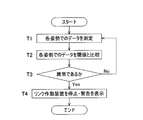
- step T1 the data in each posture is measured by the measuring unit 6 for a certain period or at every certain operation step (step T1), and the data stored in the storage unit 7 during the inspection process is obtained.
- step T2 the data stored in the storage unit 7 during the inspection process is obtained.
- step T3 the link operation device is stopped and a warning is displayed (step T4).
- the certain period may be, for example, every hour.
- the fixed operation step may be performed for each step or for a plurality of operation steps.
- the “operation step” here is an operation that is a unit for changing the attitude of the link operating device.
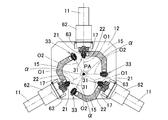
- FIG. 14 shows a configuration when an assembly error occurs in which the mounting angles of the drive source mounting member 63 and the rotation support member 21 have changed in the above embodiment.
- the center axis O1 of the rotating pair 31 of the end link members 15 on the base end side and the rotation support member 21, and each base end The center axis O2 of the rotating pair part 33 of the end link member 15 on the side and the center link member 17 is arranged so as to intersect at the center of the link hub 12 on the base end side.
- the mounting angle of the drive source mounting member 63 and the rotation support member 21 is changed, and the rotation pair of the end link member 15 and the rotation support member 21 on each base end side is changed.
- the center axis O1 and the center axis O2 of the rotating pair part 33 of the end link member 15 and the center link member 17 on the base end side do not cross at the center of the link hub 12 on the base end side.
- bearings 23 are arranged on the paired rotating parts 31 to 34 as rotating torque reducing means. Also, in order to increase the distance between the bearing outer rings, a shim 30 is interposed as shown in FIG. 8, and the inner ring of the bearing 23 is connected to the proximal end link member 15 and the spacer 29. Rigidity is improved by applying a preload with bolts and nuts through.
- the shim 30 when arranging the bearing 23 on the center link member 17, the shim 30 is forgotten to be inserted between the bearings 23 or 23, or two or more shims 30 are arranged between the bearings 23 and 23. It is conceivable that an assembling error such as an error occurs. Such a difference in the arrangement of the shims 30 may cause an extra force to be applied to the end link member 15 on the base end side due to a dimensional difference, resulting in deformation. Further, a change in the rigidity of the rotating paired parts 31 to 34 may cause a reduction in accuracy, a shortened life, and vibration. Shim removal causes a decrease in accuracy and vibration due to a decrease in rigidity, and overlap of the shim causes a decrease in life due to an increase in surface pressure.
- the abnormality detection means 4 may detect an abnormality using both the natural frequency and the torque.
Landscapes
- Engineering & Computer Science (AREA)
- Mechanical Engineering (AREA)
- General Engineering & Computer Science (AREA)
- Robotics (AREA)
- Physics & Mathematics (AREA)
- General Physics & Mathematics (AREA)
- Automation & Control Theory (AREA)
- Health & Medical Sciences (AREA)
- General Health & Medical Sciences (AREA)
- Orthopedic Medicine & Surgery (AREA)
- Manipulator (AREA)
- Transmission Devices (AREA)
Priority Applications (3)
| Application Number | Priority Date | Filing Date | Title |
|---|---|---|---|
| CN201980061333.6A CN112739506B (zh) | 2018-09-28 | 2019-09-24 | 连杆促动装置 |
| EP19867647.0A EP3858557B1 (de) | 2018-09-28 | 2019-09-24 | Verbindungsbetätigungsvorrichtung |
| US17/204,241 US12042935B2 (en) | 2018-09-28 | 2021-03-17 | Link actuation apparatus |
Applications Claiming Priority (2)
| Application Number | Priority Date | Filing Date | Title |
|---|---|---|---|
| JP2018183107A JP7274846B2 (ja) | 2018-09-28 | 2018-09-28 | リンク作動装置 |
| JP2018-183107 | 2018-09-28 |
Related Child Applications (1)
| Application Number | Title | Priority Date | Filing Date |
|---|---|---|---|
| US17/204,241 Continuation US12042935B2 (en) | 2018-09-28 | 2021-03-17 | Link actuation apparatus |
Publications (1)
| Publication Number | Publication Date |
|---|---|
| WO2020067060A1 true WO2020067060A1 (ja) | 2020-04-02 |
Family
ID=69949605
Family Applications (1)
| Application Number | Title | Priority Date | Filing Date |
|---|---|---|---|
| PCT/JP2019/037372 Ceased WO2020067060A1 (ja) | 2018-09-28 | 2019-09-24 | リンク作動装置 |
Country Status (5)
| Country | Link |
|---|---|
| US (1) | US12042935B2 (de) |
| EP (1) | EP3858557B1 (de) |
| JP (1) | JP7274846B2 (de) |
| CN (1) | CN112739506B (de) |
| WO (1) | WO2020067060A1 (de) |
Families Citing this family (2)
| Publication number | Priority date | Publication date | Assignee | Title |
|---|---|---|---|---|
| WO2020075779A1 (ja) * | 2018-10-10 | 2020-04-16 | 国立大学法人九州工業大学 | パラレルリンク機構およびリンク作動装置 |
| JP7579119B2 (ja) * | 2020-11-20 | 2024-11-07 | Ntn株式会社 | 作業装置 |
Citations (9)
| Publication number | Priority date | Publication date | Assignee | Title |
|---|---|---|---|---|
| US5893296A (en) | 1997-03-13 | 1999-04-13 | Ross-Hime Designs, Incorporated | Multiple rotatable links robotic manipulator |
| JP2000094245A (ja) | 1998-09-17 | 2000-04-04 | Fanuc Ltd | パラレルリンク機構を具備する作業装置 |
| JP2008040930A (ja) * | 2006-08-09 | 2008-02-21 | Okuma Corp | パラレルメカニズム機械の制御方法及び制御装置 |
| JP4476603B2 (ja) | 2003-08-06 | 2010-06-09 | Ntn株式会社 | リンク作動装置 |
| JP2013052501A (ja) * | 2011-09-06 | 2013-03-21 | Yaskawa Electric Corp | パラレルリンクロボット、パラレルリンクロボットシステムおよびパラレルリンクロボットの制御方法 |
| JP2013198942A (ja) * | 2012-03-23 | 2013-10-03 | Ntn Corp | リンク作動装置の制御方法およびその制御装置 |
| JP5785055B2 (ja) | 2011-11-07 | 2015-09-24 | Ntn株式会社 | リンク作動装置 |
| WO2017051866A1 (ja) * | 2015-09-25 | 2017-03-30 | Ntn株式会社 | リンク作動装置の診断装置 |
| WO2018029910A1 (ja) * | 2016-08-08 | 2018-02-15 | 三菱電機株式会社 | パラレルリンク機構の制御装置 |
Family Cites Families (17)
| Publication number | Priority date | Publication date | Assignee | Title |
|---|---|---|---|---|
| JP2005040919A (ja) * | 2003-07-24 | 2005-02-17 | Sony Corp | モーション・ベース |
| EP1690652A1 (de) | 2005-02-11 | 2006-08-16 | Force Dimension S.à.r.l | Vorrichtung zur Übertragung von Bewegungen mit einer parallelkinematischen Struktur und ihre Komponenten |
| JP2006281421A (ja) * | 2005-04-05 | 2006-10-19 | Yaskawa Electric Corp | ロボットおよびロボットの異常検出方法 |
| JP4669413B2 (ja) * | 2006-03-01 | 2011-04-13 | 株式会社クボタ | コンバインの姿勢検出装置及びコンバインの姿勢制御装置 |
| JP2007320495A (ja) * | 2006-06-02 | 2007-12-13 | Honda Motor Co Ltd | 車両用サスペンション装置 |
| EP2163226A1 (de) * | 2007-04-23 | 2010-03-17 | Golden Crab, S.L. | Exoskelett zur sicherheit und kontrolle beim schifahren |
| JP4653848B1 (ja) * | 2009-10-26 | 2011-03-16 | ファナック株式会社 | パラレルリンクロボット |
| EP2422935B1 (de) * | 2010-08-31 | 2015-02-25 | Kabushiki Kaisha Yaskawa Denki | Roboter, Robotersystem, Robotersteuerungsvorrichtung und Statusbestimmungsverfahren |
| JP5951224B2 (ja) * | 2011-11-02 | 2016-07-13 | Ntn株式会社 | リンク作動装置の原点位置初期設定方法およびリンク作動装置 |
| CN105269557B (zh) * | 2012-03-23 | 2017-06-23 | Ntn株式会社 | 连杆动作装置 |
| JP6576646B2 (ja) * | 2015-02-13 | 2019-09-18 | Ntn株式会社 | リンク作動装置を用いた多関節ロボット |
| CN105105970B (zh) * | 2015-08-04 | 2017-08-18 | 张明明 | 一种并联踝关节康复机器人及其控制方法 |
| JP6067805B1 (ja) | 2015-09-07 | 2017-01-25 | Ntn株式会社 | リンク作動装置を用いた複合作業装置 |
| JP6792390B2 (ja) * | 2015-09-25 | 2020-11-25 | Ntn株式会社 | リンク作動装置の診断装置 |
| KR101724490B1 (ko) | 2015-12-02 | 2017-04-07 | 기아자동차 주식회사 | 협업로봇을 이용한 차량 생산시스템 및 생산방법 |
| JP6572439B2 (ja) * | 2015-12-17 | 2019-09-11 | パナソニックIpマネジメント株式会社 | 作業装置および作業装置における作業方法 |
| JP6374439B2 (ja) | 2016-06-03 | 2018-08-15 | ファナック株式会社 | パラレルリンクロボットの関節部の異常検出装置及び異常検出方法 |
-
2018
- 2018-09-28 JP JP2018183107A patent/JP7274846B2/ja active Active
-
2019
- 2019-09-24 WO PCT/JP2019/037372 patent/WO2020067060A1/ja not_active Ceased
- 2019-09-24 CN CN201980061333.6A patent/CN112739506B/zh active Active
- 2019-09-24 EP EP19867647.0A patent/EP3858557B1/de active Active
-
2021
- 2021-03-17 US US17/204,241 patent/US12042935B2/en active Active
Patent Citations (9)
| Publication number | Priority date | Publication date | Assignee | Title |
|---|---|---|---|---|
| US5893296A (en) | 1997-03-13 | 1999-04-13 | Ross-Hime Designs, Incorporated | Multiple rotatable links robotic manipulator |
| JP2000094245A (ja) | 1998-09-17 | 2000-04-04 | Fanuc Ltd | パラレルリンク機構を具備する作業装置 |
| JP4476603B2 (ja) | 2003-08-06 | 2010-06-09 | Ntn株式会社 | リンク作動装置 |
| JP2008040930A (ja) * | 2006-08-09 | 2008-02-21 | Okuma Corp | パラレルメカニズム機械の制御方法及び制御装置 |
| JP2013052501A (ja) * | 2011-09-06 | 2013-03-21 | Yaskawa Electric Corp | パラレルリンクロボット、パラレルリンクロボットシステムおよびパラレルリンクロボットの制御方法 |
| JP5785055B2 (ja) | 2011-11-07 | 2015-09-24 | Ntn株式会社 | リンク作動装置 |
| JP2013198942A (ja) * | 2012-03-23 | 2013-10-03 | Ntn Corp | リンク作動装置の制御方法およびその制御装置 |
| WO2017051866A1 (ja) * | 2015-09-25 | 2017-03-30 | Ntn株式会社 | リンク作動装置の診断装置 |
| WO2018029910A1 (ja) * | 2016-08-08 | 2018-02-15 | 三菱電機株式会社 | パラレルリンク機構の制御装置 |
Non-Patent Citations (1)
| Title |
|---|
| See also references of EP3858557A4 |
Also Published As
| Publication number | Publication date |
|---|---|
| EP3858557B1 (de) | 2025-02-26 |
| US12042935B2 (en) | 2024-07-23 |
| EP3858557A1 (de) | 2021-08-04 |
| CN112739506A (zh) | 2021-04-30 |
| JP7274846B2 (ja) | 2023-05-17 |
| CN112739506B (zh) | 2024-07-12 |
| EP3858557A4 (de) | 2022-07-06 |
| JP2020049613A (ja) | 2020-04-02 |
| US20210197362A1 (en) | 2021-07-01 |
Similar Documents
| Publication | Publication Date | Title |
|---|---|---|
| US9316266B2 (en) | Parallel link mechanism, constant velocity universal joint, and link actuator | |
| US10661398B2 (en) | Link actuator to initially set position of origin | |
| US11407101B2 (en) | Link actuating device | |
| US20170211999A1 (en) | Force/torque sensor having redundant instrumentation and operative to detect faults | |
| CN102785253A (zh) | 具有机器人的异常检测功能的机器人系统及其控制方法 | |
| US10828779B2 (en) | Diagnostic device for link actuation device | |
| US12042935B2 (en) | Link actuation apparatus | |
| JP6549812B2 (ja) | トルクセンサおよびロボット | |
| US11945120B2 (en) | Robot control device, abnormality diagnosis method, and non-transitory computer readable medium | |
| JP2008040930A (ja) | パラレルメカニズム機械の制御方法及び制御装置 | |
| CN108136587B (zh) | 连杆操作装置的诊断装置 | |
| JP7353755B2 (ja) | ロボットシステム、ロボットシステムの制御方法、ロボットシステムを用いた物品の製造方法、検出装置、検出装置の制御方法、駆動装置、駆動装置の制御方法、制御プログラム及び記録媒体 | |
| US12263601B2 (en) | Angle calibration method | |
| CN117651632A (zh) | 机器人系统 | |
| JP2022094042A (ja) | 検出装置、検出方法、ロボット装置、ロボット装置の制御方法、ロボット装置を用いた物品の製造方法、駆動装置、制御プログラムおよび記録媒体 | |
| WO2024116258A1 (ja) | 工作機械、診断ツール、および、工作機械の診断方法 | |
| JP2022155647A (ja) | 減速機の状態監視装置、減速機の状態監視方法 |
Legal Events
| Date | Code | Title | Description |
|---|---|---|---|
| 121 | Ep: the epo has been informed by wipo that ep was designated in this application |
Ref document number: 19867647 Country of ref document: EP Kind code of ref document: A1 |
|
| NENP | Non-entry into the national phase |
Ref country code: DE |
|
| ENP | Entry into the national phase |
Ref document number: 2019867647 Country of ref document: EP Effective date: 20210428 |