WO2020067236A1 - 方向性電磁鋼板の製造方法および冷間圧延設備 - Google Patents
方向性電磁鋼板の製造方法および冷間圧延設備 Download PDFInfo
- Publication number
- WO2020067236A1 WO2020067236A1 PCT/JP2019/037752 JP2019037752W WO2020067236A1 WO 2020067236 A1 WO2020067236 A1 WO 2020067236A1 JP 2019037752 W JP2019037752 W JP 2019037752W WO 2020067236 A1 WO2020067236 A1 WO 2020067236A1
- Authority
- WO
- WIPO (PCT)
- Prior art keywords
- mass
- stands
- steel sheet
- rolling
- pass line
- Prior art date
- Legal status (The legal status is an assumption and is not a legal conclusion. Google has not performed a legal analysis and makes no representation as to the accuracy of the status listed.)
- Ceased
Links
Images
Classifications
-
- C—CHEMISTRY; METALLURGY
- C21—METALLURGY OF IRON
- C21D—MODIFYING THE PHYSICAL STRUCTURE OF FERROUS METALS; GENERAL DEVICES FOR HEAT TREATMENT OF FERROUS OR NON-FERROUS METALS OR ALLOYS; MAKING METAL MALLEABLE, e.g. BY DECARBURISATION OR TEMPERING
- C21D8/00—Modifying the physical properties of ferrous metals or ferrous alloys by deformation combined with, or followed by, heat treatment
- C21D8/12—Modifying the physical properties of ferrous metals or ferrous alloys by deformation combined with, or followed by, heat treatment during manufacturing of articles with special electromagnetic properties
- C21D8/1216—Modifying the physical properties of ferrous metals or ferrous alloys by deformation combined with, or followed by, heat treatment during manufacturing of articles with special electromagnetic properties characterised by the working steps
- C21D8/1227—Warm rolling
-
- C—CHEMISTRY; METALLURGY
- C21—METALLURGY OF IRON
- C21D—MODIFYING THE PHYSICAL STRUCTURE OF FERROUS METALS; GENERAL DEVICES FOR HEAT TREATMENT OF FERROUS OR NON-FERROUS METALS OR ALLOYS; MAKING METAL MALLEABLE, e.g. BY DECARBURISATION OR TEMPERING
- C21D8/00—Modifying the physical properties of ferrous metals or ferrous alloys by deformation combined with, or followed by, heat treatment
- C21D8/12—Modifying the physical properties of ferrous metals or ferrous alloys by deformation combined with, or followed by, heat treatment during manufacturing of articles with special electromagnetic properties
- C21D8/1216—Modifying the physical properties of ferrous metals or ferrous alloys by deformation combined with, or followed by, heat treatment during manufacturing of articles with special electromagnetic properties characterised by the working steps
- C21D8/1222—Hot rolling
-
- B—PERFORMING OPERATIONS; TRANSPORTING
- B21—MECHANICAL METAL-WORKING WITHOUT ESSENTIALLY REMOVING MATERIAL; PUNCHING METAL
- B21B—ROLLING OF METAL
- B21B1/00—Metal-rolling methods or mills for making semi-finished products of solid or profiled cross-section; Sequence of operations in milling trains; Layout of rolling-mill plant, e.g. grouping of stands; Succession of passes or of sectional pass alternations
- B21B1/22—Metal-rolling methods or mills for making semi-finished products of solid or profiled cross-section; Sequence of operations in milling trains; Layout of rolling-mill plant, e.g. grouping of stands; Succession of passes or of sectional pass alternations for rolling plates, strips, bands or sheets of indefinite length
- B21B1/24—Metal-rolling methods or mills for making semi-finished products of solid or profiled cross-section; Sequence of operations in milling trains; Layout of rolling-mill plant, e.g. grouping of stands; Succession of passes or of sectional pass alternations for rolling plates, strips, bands or sheets of indefinite length in a continuous or semi-continuous process
- B21B1/28—Metal-rolling methods or mills for making semi-finished products of solid or profiled cross-section; Sequence of operations in milling trains; Layout of rolling-mill plant, e.g. grouping of stands; Succession of passes or of sectional pass alternations for rolling plates, strips, bands or sheets of indefinite length in a continuous or semi-continuous process by cold-rolling, e.g. Steckel cold mill
-
- B—PERFORMING OPERATIONS; TRANSPORTING
- B21—MECHANICAL METAL-WORKING WITHOUT ESSENTIALLY REMOVING MATERIAL; PUNCHING METAL
- B21B—ROLLING OF METAL
- B21B3/00—Rolling materials of special alloys so far as the composition of the alloy requires or permits special rolling methods or sequences ; Rolling of aluminium, copper, zinc or other non-ferrous metals
- B21B3/02—Rolling special iron alloys, e.g. stainless steel
-
- B—PERFORMING OPERATIONS; TRANSPORTING
- B21—MECHANICAL METAL-WORKING WITHOUT ESSENTIALLY REMOVING MATERIAL; PUNCHING METAL
- B21C—MANUFACTURE OF METAL SHEETS, WIRE, RODS, TUBES, PROFILES OR LIKE SEMI-MANUFACTURED PRODUCTS OTHERWISE THAN BY ROLLING; AUXILIARY OPERATIONS USED IN CONNECTION WITH METAL-WORKING WITHOUT ESSENTIALLY REMOVING MATERIAL
- B21C49/00—Devices for temporarily accumulating material
-
- C—CHEMISTRY; METALLURGY
- C21—METALLURGY OF IRON
- C21D—MODIFYING THE PHYSICAL STRUCTURE OF FERROUS METALS; GENERAL DEVICES FOR HEAT TREATMENT OF FERROUS OR NON-FERROUS METALS OR ALLOYS; MAKING METAL MALLEABLE, e.g. BY DECARBURISATION OR TEMPERING
- C21D8/00—Modifying the physical properties of ferrous metals or ferrous alloys by deformation combined with, or followed by, heat treatment
- C21D8/12—Modifying the physical properties of ferrous metals or ferrous alloys by deformation combined with, or followed by, heat treatment during manufacturing of articles with special electromagnetic properties
-
- C—CHEMISTRY; METALLURGY
- C21—METALLURGY OF IRON
- C21D—MODIFYING THE PHYSICAL STRUCTURE OF FERROUS METALS; GENERAL DEVICES FOR HEAT TREATMENT OF FERROUS OR NON-FERROUS METALS OR ALLOYS; MAKING METAL MALLEABLE, e.g. BY DECARBURISATION OR TEMPERING
- C21D8/00—Modifying the physical properties of ferrous metals or ferrous alloys by deformation combined with, or followed by, heat treatment
- C21D8/12—Modifying the physical properties of ferrous metals or ferrous alloys by deformation combined with, or followed by, heat treatment during manufacturing of articles with special electromagnetic properties
- C21D8/1205—Modifying the physical properties of ferrous metals or ferrous alloys by deformation combined with, or followed by, heat treatment during manufacturing of articles with special electromagnetic properties involving particular fabrication steps or treatments of ingots or slabs
-
- C—CHEMISTRY; METALLURGY
- C21—METALLURGY OF IRON
- C21D—MODIFYING THE PHYSICAL STRUCTURE OF FERROUS METALS; GENERAL DEVICES FOR HEAT TREATMENT OF FERROUS OR NON-FERROUS METALS OR ALLOYS; MAKING METAL MALLEABLE, e.g. BY DECARBURISATION OR TEMPERING
- C21D8/00—Modifying the physical properties of ferrous metals or ferrous alloys by deformation combined with, or followed by, heat treatment
- C21D8/12—Modifying the physical properties of ferrous metals or ferrous alloys by deformation combined with, or followed by, heat treatment during manufacturing of articles with special electromagnetic properties
- C21D8/1216—Modifying the physical properties of ferrous metals or ferrous alloys by deformation combined with, or followed by, heat treatment during manufacturing of articles with special electromagnetic properties characterised by the working steps
- C21D8/1233—Cold rolling
-
- C—CHEMISTRY; METALLURGY
- C21—METALLURGY OF IRON
- C21D—MODIFYING THE PHYSICAL STRUCTURE OF FERROUS METALS; GENERAL DEVICES FOR HEAT TREATMENT OF FERROUS OR NON-FERROUS METALS OR ALLOYS; MAKING METAL MALLEABLE, e.g. BY DECARBURISATION OR TEMPERING
- C21D8/00—Modifying the physical properties of ferrous metals or ferrous alloys by deformation combined with, or followed by, heat treatment
- C21D8/12—Modifying the physical properties of ferrous metals or ferrous alloys by deformation combined with, or followed by, heat treatment during manufacturing of articles with special electromagnetic properties
- C21D8/1244—Modifying the physical properties of ferrous metals or ferrous alloys by deformation combined with, or followed by, heat treatment during manufacturing of articles with special electromagnetic properties characterised by the heat treatment
- C21D8/1255—Modifying the physical properties of ferrous metals or ferrous alloys by deformation combined with, or followed by, heat treatment during manufacturing of articles with special electromagnetic properties characterised by the heat treatment with diffusion of elements, e.g. decarburising, nitriding
-
- C—CHEMISTRY; METALLURGY
- C21—METALLURGY OF IRON
- C21D—MODIFYING THE PHYSICAL STRUCTURE OF FERROUS METALS; GENERAL DEVICES FOR HEAT TREATMENT OF FERROUS OR NON-FERROUS METALS OR ALLOYS; MAKING METAL MALLEABLE, e.g. BY DECARBURISATION OR TEMPERING
- C21D8/00—Modifying the physical properties of ferrous metals or ferrous alloys by deformation combined with, or followed by, heat treatment
- C21D8/12—Modifying the physical properties of ferrous metals or ferrous alloys by deformation combined with, or followed by, heat treatment during manufacturing of articles with special electromagnetic properties
- C21D8/1244—Modifying the physical properties of ferrous metals or ferrous alloys by deformation combined with, or followed by, heat treatment during manufacturing of articles with special electromagnetic properties characterised by the heat treatment
- C21D8/1261—Modifying the physical properties of ferrous metals or ferrous alloys by deformation combined with, or followed by, heat treatment during manufacturing of articles with special electromagnetic properties characterised by the heat treatment following hot rolling
-
- C—CHEMISTRY; METALLURGY
- C21—METALLURGY OF IRON
- C21D—MODIFYING THE PHYSICAL STRUCTURE OF FERROUS METALS; GENERAL DEVICES FOR HEAT TREATMENT OF FERROUS OR NON-FERROUS METALS OR ALLOYS; MAKING METAL MALLEABLE, e.g. BY DECARBURISATION OR TEMPERING
- C21D8/00—Modifying the physical properties of ferrous metals or ferrous alloys by deformation combined with, or followed by, heat treatment
- C21D8/12—Modifying the physical properties of ferrous metals or ferrous alloys by deformation combined with, or followed by, heat treatment during manufacturing of articles with special electromagnetic properties
- C21D8/1244—Modifying the physical properties of ferrous metals or ferrous alloys by deformation combined with, or followed by, heat treatment during manufacturing of articles with special electromagnetic properties characterised by the heat treatment
- C21D8/1272—Final recrystallisation annealing
-
- C—CHEMISTRY; METALLURGY
- C21—METALLURGY OF IRON
- C21D—MODIFYING THE PHYSICAL STRUCTURE OF FERROUS METALS; GENERAL DEVICES FOR HEAT TREATMENT OF FERROUS OR NON-FERROUS METALS OR ALLOYS; MAKING METAL MALLEABLE, e.g. BY DECARBURISATION OR TEMPERING
- C21D8/00—Modifying the physical properties of ferrous metals or ferrous alloys by deformation combined with, or followed by, heat treatment
- C21D8/12—Modifying the physical properties of ferrous metals or ferrous alloys by deformation combined with, or followed by, heat treatment during manufacturing of articles with special electromagnetic properties
- C21D8/1277—Modifying the physical properties of ferrous metals or ferrous alloys by deformation combined with, or followed by, heat treatment during manufacturing of articles with special electromagnetic properties involving a particular surface treatment
-
- C—CHEMISTRY; METALLURGY
- C21—METALLURGY OF IRON
- C21D—MODIFYING THE PHYSICAL STRUCTURE OF FERROUS METALS; GENERAL DEVICES FOR HEAT TREATMENT OF FERROUS OR NON-FERROUS METALS OR ALLOYS; MAKING METAL MALLEABLE, e.g. BY DECARBURISATION OR TEMPERING
- C21D8/00—Modifying the physical properties of ferrous metals or ferrous alloys by deformation combined with, or followed by, heat treatment
- C21D8/12—Modifying the physical properties of ferrous metals or ferrous alloys by deformation combined with, or followed by, heat treatment during manufacturing of articles with special electromagnetic properties
- C21D8/1277—Modifying the physical properties of ferrous metals or ferrous alloys by deformation combined with, or followed by, heat treatment during manufacturing of articles with special electromagnetic properties involving a particular surface treatment
- C21D8/1283—Application of a separating or insulating coating
-
- C—CHEMISTRY; METALLURGY
- C22—METALLURGY; FERROUS OR NON-FERROUS ALLOYS; TREATMENT OF ALLOYS OR NON-FERROUS METALS
- C22C—ALLOYS
- C22C38/00—Ferrous alloys, e.g. steel alloys
-
- C—CHEMISTRY; METALLURGY
- C22—METALLURGY; FERROUS OR NON-FERROUS ALLOYS; TREATMENT OF ALLOYS OR NON-FERROUS METALS
- C22C—ALLOYS
- C22C38/00—Ferrous alloys, e.g. steel alloys
- C22C38/001—Ferrous alloys, e.g. steel alloys containing N
-
- C—CHEMISTRY; METALLURGY
- C22—METALLURGY; FERROUS OR NON-FERROUS ALLOYS; TREATMENT OF ALLOYS OR NON-FERROUS METALS
- C22C—ALLOYS
- C22C38/00—Ferrous alloys, e.g. steel alloys
- C22C38/002—Ferrous alloys, e.g. steel alloys containing In, Mg, or other elements not provided for in one single group C22C38/001 - C22C38/60
-
- C—CHEMISTRY; METALLURGY
- C22—METALLURGY; FERROUS OR NON-FERROUS ALLOYS; TREATMENT OF ALLOYS OR NON-FERROUS METALS
- C22C—ALLOYS
- C22C38/00—Ferrous alloys, e.g. steel alloys
- C22C38/008—Ferrous alloys, e.g. steel alloys containing tin
-
- C—CHEMISTRY; METALLURGY
- C22—METALLURGY; FERROUS OR NON-FERROUS ALLOYS; TREATMENT OF ALLOYS OR NON-FERROUS METALS
- C22C—ALLOYS
- C22C38/00—Ferrous alloys, e.g. steel alloys
- C22C38/02—Ferrous alloys, e.g. steel alloys containing silicon
-
- C—CHEMISTRY; METALLURGY
- C22—METALLURGY; FERROUS OR NON-FERROUS ALLOYS; TREATMENT OF ALLOYS OR NON-FERROUS METALS
- C22C—ALLOYS
- C22C38/00—Ferrous alloys, e.g. steel alloys
- C22C38/04—Ferrous alloys, e.g. steel alloys containing manganese
-
- C—CHEMISTRY; METALLURGY
- C22—METALLURGY; FERROUS OR NON-FERROUS ALLOYS; TREATMENT OF ALLOYS OR NON-FERROUS METALS
- C22C—ALLOYS
- C22C38/00—Ferrous alloys, e.g. steel alloys
- C22C38/06—Ferrous alloys, e.g. steel alloys containing aluminium
-
- C—CHEMISTRY; METALLURGY
- C22—METALLURGY; FERROUS OR NON-FERROUS ALLOYS; TREATMENT OF ALLOYS OR NON-FERROUS METALS
- C22C—ALLOYS
- C22C38/00—Ferrous alloys, e.g. steel alloys
- C22C38/08—Ferrous alloys, e.g. steel alloys containing nickel
-
- C—CHEMISTRY; METALLURGY
- C22—METALLURGY; FERROUS OR NON-FERROUS ALLOYS; TREATMENT OF ALLOYS OR NON-FERROUS METALS
- C22C—ALLOYS
- C22C38/00—Ferrous alloys, e.g. steel alloys
- C22C38/12—Ferrous alloys, e.g. steel alloys containing tungsten, tantalum, molybdenum, vanadium, or niobium
-
- C—CHEMISTRY; METALLURGY
- C22—METALLURGY; FERROUS OR NON-FERROUS ALLOYS; TREATMENT OF ALLOYS OR NON-FERROUS METALS
- C22C—ALLOYS
- C22C38/00—Ferrous alloys, e.g. steel alloys
- C22C38/16—Ferrous alloys, e.g. steel alloys containing copper
-
- C—CHEMISTRY; METALLURGY
- C22—METALLURGY; FERROUS OR NON-FERROUS ALLOYS; TREATMENT OF ALLOYS OR NON-FERROUS METALS
- C22C—ALLOYS
- C22C38/00—Ferrous alloys, e.g. steel alloys
- C22C38/18—Ferrous alloys, e.g. steel alloys containing chromium
- C22C38/34—Ferrous alloys, e.g. steel alloys containing chromium with more than 1.5% by weight of silicon
-
- C—CHEMISTRY; METALLURGY
- C22—METALLURGY; FERROUS OR NON-FERROUS ALLOYS; TREATMENT OF ALLOYS OR NON-FERROUS METALS
- C22C—ALLOYS
- C22C38/00—Ferrous alloys, e.g. steel alloys
- C22C38/18—Ferrous alloys, e.g. steel alloys containing chromium
- C22C38/40—Ferrous alloys, e.g. steel alloys containing chromium with nickel
- C22C38/42—Ferrous alloys, e.g. steel alloys containing chromium with nickel with copper
-
- C—CHEMISTRY; METALLURGY
- C22—METALLURGY; FERROUS OR NON-FERROUS ALLOYS; TREATMENT OF ALLOYS OR NON-FERROUS METALS
- C22C—ALLOYS
- C22C38/00—Ferrous alloys, e.g. steel alloys
- C22C38/18—Ferrous alloys, e.g. steel alloys containing chromium
- C22C38/40—Ferrous alloys, e.g. steel alloys containing chromium with nickel
- C22C38/44—Ferrous alloys, e.g. steel alloys containing chromium with nickel with molybdenum or tungsten
-
- C—CHEMISTRY; METALLURGY
- C22—METALLURGY; FERROUS OR NON-FERROUS ALLOYS; TREATMENT OF ALLOYS OR NON-FERROUS METALS
- C22C—ALLOYS
- C22C38/00—Ferrous alloys, e.g. steel alloys
- C22C38/18—Ferrous alloys, e.g. steel alloys containing chromium
- C22C38/40—Ferrous alloys, e.g. steel alloys containing chromium with nickel
- C22C38/48—Ferrous alloys, e.g. steel alloys containing chromium with nickel with niobium or tantalum
-
- C—CHEMISTRY; METALLURGY
- C22—METALLURGY; FERROUS OR NON-FERROUS ALLOYS; TREATMENT OF ALLOYS OR NON-FERROUS METALS
- C22C—ALLOYS
- C22C38/00—Ferrous alloys, e.g. steel alloys
- C22C38/60—Ferrous alloys, e.g. steel alloys containing lead, selenium, tellurium, or antimony, or more than 0.04% by weight of sulfur
-
- H—ELECTRICITY
- H01—ELECTRIC ELEMENTS
- H01F—MAGNETS; INDUCTANCES; TRANSFORMERS; SELECTION OF MATERIALS FOR THEIR MAGNETIC PROPERTIES
- H01F1/00—Magnets or magnetic bodies characterised by the magnetic materials therefor; Selection of materials for their magnetic properties
- H01F1/01—Magnets or magnetic bodies characterised by the magnetic materials therefor; Selection of materials for their magnetic properties of inorganic materials
- H01F1/03—Magnets or magnetic bodies characterised by the magnetic materials therefor; Selection of materials for their magnetic properties of inorganic materials characterised by their coercivity
- H01F1/12—Magnets or magnetic bodies characterised by the magnetic materials therefor; Selection of materials for their magnetic properties of inorganic materials characterised by their coercivity of soft-magnetic materials
- H01F1/14—Magnets or magnetic bodies characterised by the magnetic materials therefor; Selection of materials for their magnetic properties of inorganic materials characterised by their coercivity of soft-magnetic materials metals or alloys
- H01F1/147—Alloys characterised by their composition
-
- B—PERFORMING OPERATIONS; TRANSPORTING
- B21—MECHANICAL METAL-WORKING WITHOUT ESSENTIALLY REMOVING MATERIAL; PUNCHING METAL
- B21B—ROLLING OF METAL
- B21B2261/00—Product parameters
- B21B2261/20—Temperature
-
- B—PERFORMING OPERATIONS; TRANSPORTING
- B21—MECHANICAL METAL-WORKING WITHOUT ESSENTIALLY REMOVING MATERIAL; PUNCHING METAL
- B21B—ROLLING OF METAL
- B21B2265/00—Forming parameters
- B21B2265/14—Reduction rate
-
- C—CHEMISTRY; METALLURGY
- C21—METALLURGY OF IRON
- C21D—MODIFYING THE PHYSICAL STRUCTURE OF FERROUS METALS; GENERAL DEVICES FOR HEAT TREATMENT OF FERROUS OR NON-FERROUS METALS OR ALLOYS; MAKING METAL MALLEABLE, e.g. BY DECARBURISATION OR TEMPERING
- C21D1/00—General methods or devices for heat treatment, e.g. annealing, hardening, quenching or tempering
- C21D1/26—Methods of annealing
- C21D1/30—Stress-relieving
-
- C—CHEMISTRY; METALLURGY
- C21—METALLURGY OF IRON
- C21D—MODIFYING THE PHYSICAL STRUCTURE OF FERROUS METALS; GENERAL DEVICES FOR HEAT TREATMENT OF FERROUS OR NON-FERROUS METALS OR ALLOYS; MAKING METAL MALLEABLE, e.g. BY DECARBURISATION OR TEMPERING
- C21D2201/00—Treatment for obtaining particular effects
- C21D2201/05—Grain orientation
Definitions
- the present invention relates to a method for producing a grain-oriented electrical steel sheet having excellent magnetic properties, and a cold rolling facility used for the method.
- -Oriented electrical steel sheets are steel sheets having excellent magnetic properties and having a crystal structure (Goth orientation) in which the ⁇ 001> orientation, which is the axis of easy magnetization of iron, is highly integrated in the rolling direction of the steel sheet.
- Such a grain-oriented electrical steel sheet generally contains about 4.5 mass% or less of Si, and further contains a component called MnS, MnSe, or AlN, which is called an inhibitor, in order to develop secondary recrystallization.
- MnS, MnSe, or AlN which is called an inhibitor
- Patent Literature 1 proposes a technique (inhibitor-less method) capable of expressing secondary recrystallization without including the inhibitor-forming component.
- the inhibitor-less method is a technology that uses a highly purified steel material and expresses secondary recrystallization by controlling the texture (texture). Since high-temperature slab heating before hot rolling is not required, low-cost Although it has the advantage that a grain-oriented electrical steel sheet can be manufactured, delicate condition control is required for forming a texture.
- Patent Literature 2 proposes a method of performing a heat treatment (aging treatment) on a cold-rolled sheet at a low temperature during rolling. This method diffuses carbon and nitrogen, which are solid solution elements, at a low temperature to fix dislocations introduced by rolling, hinders the movement of dislocations, promotes shear deformation in subsequent rolling, and reduces the rolling texture. Is to improve.
- Patent Document 3 discloses that the cooling rate of annealing before hot-rolled sheet annealing or finish cold rolling (final cold rolling) is 30 ° C./s or more, and the sheet temperature is raised to 150 to 300 ° C. during finish cold rolling.
- a technique for performing aging between passes, which is maintained for more than one minute, twice or more is disclosed.
- Patent Literature 4 proposes a technique using a dynamic aging effect in which dislocations introduced by rolling are immediately fixed by carbon or nitrogen by setting the temperature of a steel sheet during rolling to a high temperature (warm rolling). ing.
- the cold rolling step is a very important step from the viewpoint of controlling the texture.
- a tandem rolling mill in which a reverse rolling mill (Patent Document 5) and a plurality of stands (also referred to as “std”) are arranged in series is used for cold rolling to obtain the final sheet thickness (product thickness). Is often used.
- a reverse rolling mill that can be maintained in a state wound around a coil for a long time after one-pass rolling and subjected to so-called aging treatment is advantageous. Have been.
- JP 2000-129356 A JP-A-50-016610 JP 08-253816 A JP-A-01-215925 Japanese Patent Publication No. 54-013846 Japanese Patent Publication No. 54-029182
- the time (pass time) for the steel sheet to pass between a plurality of stands constituting the rolling mill depends on the distance between the stands, which is the specification of the rolling mill, and If the speed supplied to one stand and the rolling speed or reduction ratio distribution of each stand are determined, it can be calculated. For example, assuming that a steel plate having a thickness of 2 mm is rolled by a five tandem rolling mill in which five stands are arranged at 1.5 m intervals, the supply speed of the steel plate on the # 1 stand entrance side is 100 mpm, and the reduction of each stand is reduced.
- the plate thickness on the exit side of the # 1 stand is 1.5 mm
- the steel plate speed is about 133 mpm
- the pass time for the steel plate to pass between the # 1-2 stand is about 0.675 s.
- the thickness of the # 4 stand exit side is 0.63 mm
- the steel sheet speed is 316 mpm
- the pass time of the steel sheet passing between the # 4 and # 5 stands is about 0.285 s. Only in a short time.
- the present invention has been made in view of the above-mentioned problems of the related art, and an object of the present invention is to employ a tandem rolling mill for cold rolling when manufacturing a grain-oriented electrical steel sheet using an inhibitor-less steel material. Even in the case of, the present invention aims to provide a method for manufacturing a grain-oriented electrical steel sheet that can effectively express aging between passes and obtain excellent magnetic properties, and provide a cold rolling facility used in the manufacturing method. .
- the present inventors have a method of manufacturing a grain-oriented electrical steel sheet using a steel material containing no inhibitor-forming component, in which texture control is important, and a tandem rolling mill for final cold rolling. And intensive studies were conducted focusing on the effect of aging conditions between stands in tandem rolling on the primary recrystallization texture. As a result, even when the tandem rolling mill is used for final cold rolling, the pass time of the steel sheet between stands, that is, the aging time, even if the time is slightly extended, the primary recrystallization texture is improved. It has been found that the effect of improving the texture by extending the time between passes is particularly large in the later stage of the tandem rolling mill where the total draft is increased, and the present invention has been developed.
- the present invention provides C: 0.01 to 0.10 mass%, Si: 2.0 to 4.5 mass%, Mn: 0.01 to 0.5 mass%, sol.
- Al steel containing 0.0020 mass% or more and less than 0.0100 mass%, N: containing less than 0.0080 mass%, and further containing S, Se and O each containing less than 0.0050 mass%, with the balance being Fe and inevitable impurities.
- After the slab is reheated to a temperature of 1300 ° C. or less, it is hot-rolled, cold-rolled once or two or more times with intermediate annealing to obtain a cold-rolled sheet having a final thickness, and then de-rolled.
- Primary recrystallization annealing also serving as carbon annealing, after applying an annealing separator on the surface of the steel sheet, in the method of manufacturing a directional electrical steel sheet to apply a finish annealing to secondary recrystallization, the final cold rolling to the final sheet thickness
- the cold rolling is performed by using a tandem rolling mill so that the total draft is 80% or more, and the sheet temperature between at least one stand is 150 to 280 ° C., and the distance between the stands is set.
- L (m) the speed of the steel sheet passing between the stands is V (mpm)
- T (min) the pass time of the steel sheet passing between the stands is expressed by the following (1).
- the present invention proposes a method for producing a grain-oriented electrical steel sheet, characterized in that rolling is performed by extending the pass line length of the steel sheet between the stands so as to satisfy the following.
- the method of manufacturing a grain-oriented electrical steel sheet according to the present invention is characterized in that the length of the pass line of the steel sheet between the stands is extended between stands having a total draft of 66% or more.
- the steel slab used in the method for producing a grain-oriented electrical steel sheet of the present invention further comprises Ni: 0.005 to 1.50 mass%, Sn: 0.005 to 0.50 mass%, Nb : 0.0005 to 0.0100 mass%, Mo: 0.01 to 0.50 mass%, Sb: 0.005 to 0.50 mass%, Cu: 0.01 to 1.50 mass%, P: 0.005 to 0 .150 mass%, Cr: 0.01 to 1.50 mass%, and Bi: 0.0005 to 0.05 mass%.
- the present invention provides a tandem rolling mill comprising a plurality of stands, which cold-rolls a steel sheet to a final thickness, by setting a pass line length of the steel sheet between the stands between any one or more stands. And a path line extending mechanism for making the path line longer than at least two movable rolls for changing the pass line, and at least one of the movable rolls is different from the reference horizontal pass line.
- a cold rolling facility wherein the cold rolling facility is arranged at a position opposite to the upper and lower rolls.
- the cold rolling equipment of the present invention is characterized in that at least one of the movable rolls for changing the pass line arranged between the stands has a heating function.
- the above-mentioned pass line extending mechanism in the cold rolling equipment of the present invention is characterized in that the length of the pass line of the steel sheet between stands can be extended to 1.3 times or more the distance between stands.
- the cold rolling equipment of the present invention is characterized in that the above-mentioned pass line extending mechanism is installed between stands where the total draft is 66% or more.
- the cold rolling equipment of the present invention is characterized in that the steel sheet to be rolled is an electromagnetic steel sheet.
- the texture can be improved through aging between passes, so that the directional electromagnetic having excellent magnetic properties can be obtained.
- Steel plates can be manufactured at low cost.
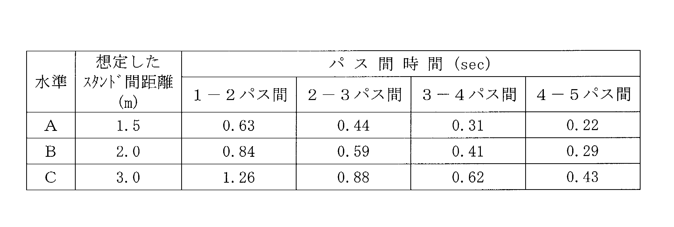
- the temperature of the steel sheet on the exit side of each of the first to fifth passes was controlled to be 200 ° C. (constant). Therefore, at the level A in Table 2, the steel sheet after each pass is 0.63 s between 1-2 passes, 0.44 s between 2-3 passes, and 0. This means that 0.22 s interpass aging has been performed between the 31 s and 4-5 passes. Further, at the level B, the steel sheet after each pass has a temperature of 200 ° C. at 0.84 s between 1-2 passes, 0.59 s between 2-3 passes, and 0.41 s between 3-4 passes. This means that 0.29 s interpass aging has been performed between -5 passes.
- the steel sheet after each pass is 1.26 s between 1-2 passes, 0.88 s between 2-3 passes, 0.62 s between 3-4 passes at a temperature of 200 ° C. This means that 0.43 s inter-pass aging has been performed between -5 passes.
- the cold-rolled sheet rolled to a final sheet thickness of 0.30 mm as described above is then subjected to primary recrystallization annealing also serving as decarburizing annealing at 840 ° C. ⁇ 100 s in a wet hydrogen atmosphere, and then subjected to an X-ray positive electrode.
- the above value is one of the indices indicating the amount of the ⁇ 110 ⁇ ⁇ 001> orientation that is the core of the secondary recrystallization, and is higher as the texture of the steel sheet after the primary recrystallization annealing is improved. Indicates a value.
- An increase in the number of nuclei of secondary recrystallization also means that the starting point of secondary recrystallization increases and secondary recrystallized grains become smaller, so that iron loss characteristics are improved.
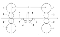
- FIG. 2 shows two stands extracted from a tandem rolling mill, and a pass line extending mechanism including a fixed roll 3 and a movable roll 4 is provided between the two stands.
- a pass line extending mechanism including a fixed roll 3 and a movable roll 4 is provided between the two stands.
- the pass line extending mechanism is similar to the tension control mechanism installed between the stands of the tandem rolling mill. However, in this mechanism, the pass line length is 1.3 times or more the distance between the stands. Cannot be extended.
- the present invention has been developed based on the above new findings.
- C 0.01 to 0.10 mass%
- C is an element useful for improving the primary recrystallization texture, and must contain at least 0.01 mass%.
- the C content is in the range of 0.01 to 0.10 mass%.
- the content is preferably in the range of 0.01 to 0.06 mass%.
- Si 2.0 to 4.5 mass%
- Si is a useful element that increases the specific resistance of steel and reduces iron loss.
- Si is contained in an amount of 2.0 mass% or more.
- the Si content is set in the range of 2.0 to 4.5 mass%. Preferably, it is in the range of 2.5 to 4.0 mass%.
- Mn 0.01 to 0.5 mass%
- Mn has an effect of improving workability in hot rolling, and also controls an oxide film formation at the time of primary recrystallization annealing, and thus has a useful effect of promoting forsterite film formation at the time of secondary recrystallization. Element. Therefore, from the viewpoint of obtaining the above effects, Mn needs to be contained at 0.01 mass% or more. However, when the Mn content exceeds 0.5 mass%, the primary recrystallization texture is deteriorated, and the magnetic properties are deteriorated. Therefore, the Mn content is in the range of 0.01 to 0.5 mass%. Preferably, it is in the range of 0.03 to 0.3 mass%.
- sol. Al 0.0020 mass% or more and less than 0.0100 mass%
- Al has a high affinity for oxygen, and by adding a small amount in the steelmaking stage, reduces the amount of dissolved oxygen in the steel and leads to deterioration of iron loss characteristics.
- Sol. It is necessary to contain 0.0020 mass% or more of Al. However, since Al forms a dense oxide film on the surface of the steel sheet and inhibits decarburization, Al. Limit to less than 0.0100 mass% with Al.
- sol. The Al content is in the range of 0.0030 to 0.0090 mass%.
- N less than 0.0080 mass% N is an unnecessary element in the present invention.
- the content of N for forming a nitride is 0.0080 mass% or more, the texture is increased due to grain boundary segregation and formation of nitride. This causes an adverse effect such as deterioration of the device. Further, it may cause defects such as blisters during slab heating. Therefore, the content of N is limited to less than 0.0080 mass%. Preferably it is 0.0060 mass% or less.
- S, Se, and O each less than 0.0050 mass%
- S, Se, and O are elements that form precipitates and oxides that serve as inhibitors, and when each of these elements becomes 0.0050 mass% or more, the slab is heated.
- Precipitated precipitates such as MnS and MnSe and coarse oxides make the primary recrystallization structure nonuniform, making it difficult to develop secondary recrystallization. Therefore, S, Se and O are all limited to less than 0.0050 mass%. Preferably, they are each 0.0030 mass% or less.
- Ni 0.005 to 1.50 mass%
- Ni has the effect of improving the magnetic properties by increasing the uniformity of the structure of the hot-rolled sheet.
- Ni can be contained in an amount of 0.005 mass% or more.
- Ni is preferably contained in the range of 0.005 to 1.50 mass%. More preferably, it is in the range of 0.01 to 1.0 mass%.
- Sn 0.005 to 0.50 mass%
- Sn has an effect of suppressing nitriding and oxidation of the steel sheet in the secondary recrystallization annealing, promoting generation of secondary recrystallized grains having a favorable crystal orientation, and improving magnetic properties.
- the above effect can be obtained by containing 0.005 mass% or more.
- Sn is preferably contained in the range of 0.005 to 0.50 mass%. More preferably, it is in the range of 0.01 to 0.30 mass%.
- Nb 0.0005 to 0.0100 mass%
- Mo 0.01 to 0.50 mass%
- Nb and Mo have an effect of preventing generation of scabs during hot rolling, for example, by suppressing slab surface cracks during slab heating.
- the above effects are obtained when the Nb content is 0.0005% by mass or more and the Mo content is 0.01% by mass or more.
- Nb content exceeds 0.0100 mass% and the Mo content exceeds 0.50 mass%, the amount of generated carbides and nitrides increases, so that they remain in the final product and cause iron loss deterioration. Become. Therefore, Nb is preferably in the range of 0.0005 to 0.0100 mass%, and Mo is preferably in the range of 0.01 to 0.50 mass%. The more preferable range of Mo is 0.01 to 0.30 mass%.
- Sb 0.005 to 0.50 mass%
- Sb has the effect of suppressing oxidation of the steel sheet surface, and also suppresses oxidation and nitridation during secondary recrystallization, thereby promoting the growth of secondary recrystallization having a good crystal orientation and improving magnetic properties. There is also the effect of doing.
- the content is preferably 0.005 mass% or more.
- Sb is preferably contained in the range of 0.005 to 0.50 mass%. More preferably, it is in the range of 0.01 to 0.30 mass%.
- Cu 0.01 to 1.50 mass%
- Cu like Sb, has the function of suppressing the oxidation of the steel sheet surface, and by suppressing the oxidation of the steel sheet surface during secondary recrystallization annealing, promotes the growth of secondary recrystallization having a good crystal orientation. This has the effect of improving the magnetic characteristics.
- the above effect can be obtained by containing 0.01 mass% or more. However, when the content exceeds 1.50 mass%, the hot rollability is lowered. Therefore, Cu is preferably contained in the range of 0.01 to 1.50 mass%. More preferably, it is in the range of 0.01 to 1.0 mass%.
- P 0.005 to 0.150 mass%
- P has a function of stabilizing the formation of a forsterite film through the formation of a subscale during decarburization annealing.
- the above effects can be obtained by containing 0.005 mass% or more.
- P is preferably contained in the range of 0.005 to 0.150 mass%. More preferably, it is in the range of 0.01 to 0.10 mass%.
- Cr 0.01 to 1.50 mass%
- Cr has a function of stabilizing the formation of the forsterite film through the formation of subscale during decarburizing annealing. The above effect can be obtained by containing 0.01 mass% or more. On the other hand, if the Cr content exceeds 1.50 mass%, secondary recrystallization becomes difficult, and the magnetic properties deteriorate. Therefore, Cr is preferably contained in the range of 0.01 to 1.50 mass%. More preferably, it is in the range of 0.01 to 1.0 mass%.
- Bi 0.0005 to 0.05 mass%
- Bi is an element effective for improving the magnetic properties, and can be contained as necessary. However, the above effect is small at less than 0.0005% by mass, whereas when it exceeds 0.05% by mass, the formation of a forsterite film is inhibited. Therefore, Bi is preferably contained in the range of 0.0005 to 0.05 mass%. More preferably, it is in the range of 0.001 to 0.03 mass%.
- a method for manufacturing a grain-oriented electrical steel sheet according to the present invention will be described.
- a steel material adjusted to the above-described component composition conforming to the present invention is melted by a conventional refining process, and then made into a steel material (slab) by a continuous casting method or an ingot-bulking rolling method.
- the slab is subjected to hot rolling after or without reheating.
- the reheating temperature is preferably in the range of 1000 to 1300 ° C.
- slab heating exceeding 1300 ° C. has no technical meaning and only increases costs.
- the temperature is lower than 1000 ° C., the load of hot rolling increases and rolling becomes difficult.
- the rolling conditions in the hot rolling may be performed according to a conventional method, and are not particularly limited.
- the hot-rolled sheet obtained by the above-mentioned hot rolling is preferably subjected to hot-rolled sheet annealing when importance is placed on magnetic properties.
- the soaking condition is preferably in the range of 950 to 1080 ° C. ⁇ 20 to 180 s. If the temperature is less than 950 ° C. or the time is less than 20 s, the effect of hot-rolled sheet annealing is not sufficiently obtained, while if the temperature exceeds 1080 ° C. or the time exceeds 180 s, the crystal grains become too coarse. This is because there is a risk that the sheet will break during cold rolling.
- the hot-rolled sheet after the hot rolling or hot-rolled sheet annealing is pickled and descaled, and then subjected to a single cold rolling or two or more cold rollings sandwiching intermediate annealing to form a final sheet.
- Cold rolling (final cold rolling) to make a cold-rolled sheet having the final thickness is the most important step in the present invention, and it is necessary to perform the total rolling reduction at 80% or more using a tandem rolling mill. It is. If the total rolling reduction is less than 80%, a good primary recrystallization texture cannot be obtained.
- a preferable total rolling reduction is 85% or more.
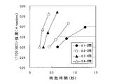
- the pass line extending mechanism can extend the pass line length of the steel plate between stands to at least 1.3 times the pass line length of the steel plate during normal rolling, that is, the distance L between stands. This is because, as shown in FIG. 1 described above, by extending the length of the pass line to 1.3 times or more the distance L between stands, the effect of aging between passes becomes remarkable. More preferably, it is 1.5 times or more. However, the texture improvement effect by inter-pass aging is more effective as the aging time is longer. For example, the effect is recognized even when the aging time is longer than 5 min. There is. Therefore, the extension of the inter-stand time between stands by the pass line extension mechanism is preferably set to 8 s at the maximum. In consideration of productivity, the aging time between passes between stands is more preferably 4 s or less.
- the texture improvement effect by aging between passes can be obtained by aging between any stands.
- the post-tandem rolling stage in which the density of the transition introduced by rolling is high is more remarkable. Becomes Therefore, when the above-mentioned pass line extending mechanism is installed, it is preferable to install it between the subsequent stands where the total draft is 66% or more.
- the temperature of the steel sheet itself must be raised to a certain temperature or more before tandem rolling. It is necessary to perform warm rolling for rolling.
- the temperature of the steel sheet needs to be in the range of 150 to 280 ° C. Preferably, it is in the range of 180 to 280 ° C.
- the means for heating the steel sheet is not particularly limited, and any of induction heating, direct current heating, and radiant heating using an electric heater or the like may be used. In the latter stage of the tandem rolling mill, it is also possible to use the heat generated by processing by rolling.
- a steel sheet can be stably and efficiently heated by imparting a heating function to a roll used for extending the pass line.
- the roll heating method is not particularly limited as long as the steel strip can be heated by heat transfer.
- a roll containing a resistance heater or an induction heater or a medium such as a high-temperature gas may be introduced. Rolls and the like can be suitably used.
- the cold-rolled sheet rolled to the above-mentioned final thickness is subjected to primary recrystallization annealing also serving as decarburizing annealing.
- the purpose of this primary recrystallization annealing is to recrystallize a cold-rolled sheet having a rolled structure to adjust the primary recrystallization texture and grain size to be optimal for secondary recrystallization, and to add an annealing atmosphere of wet hydrogen.
- an oxidizing wet hydrogen atmosphere such as a nitrogen or wet hydrogen argon atmosphere
- the carbon in the steel is reduced to an amount (0.005 mass% or less) at which magnetic aging does not occur.
- the purpose is to form an appropriate oxide film on the surface.
- the primary recrystallization annealing is preferably performed at a temperature of 750 to 900 ° C. in a wet hydrogen atmosphere optimal for decarburization conditions.
- the steel sheet after the above-mentioned primary recrystallization annealing is subjected to finish annealing after applying an annealing separator on the steel sheet surface and drying the steel sheet.
- an annealing separator in order to form a forsterite film on the surface of the steel sheet after the finish annealing, it is preferable to use magnesia (MgO) as a main component.
- MgO magnesia
- adding an appropriate amount of a Ti oxide, an Sr compound, or the like as an auxiliary agent to the annealing separator makes it advantageous to form a forsterite film having excellent film characteristics.
- TiO 2 , Sr (OH) 2 , SrSO 4, or the like which is an auxiliary agent for uniformizing the formation of a forsterite film, also works advantageously for improving the peel resistance of the film.
- the finish annealing subsequent to the application of the annealing separator is performed to develop secondary recrystallization and to form a forsterite film.
- any of N 2 , Ar and H 2 or a mixed gas thereof can be used.
- a temperature range near the secondary recrystallization temperature may be heated at a slower rate of temperature increase, and the same effect can be obtained.
- the steel sheet after the finish annealing is preferably subjected to flattening annealing for correcting the curl during the finish annealing.
- an insulating coating may be applied and baked on the steel sheet surface after the finish annealing depending on the use.
- phosphate-chromate-colloidal silica described in JP-A-50-79442 and JP-A-48-39338. It is preferable to apply a tension-imparting type insulating coating containing Ni on the surface of the steel sheet and then bake it at a temperature of about 800 ° C. Note that the baking of the insulating film may be performed together with the above-described flattening annealing.
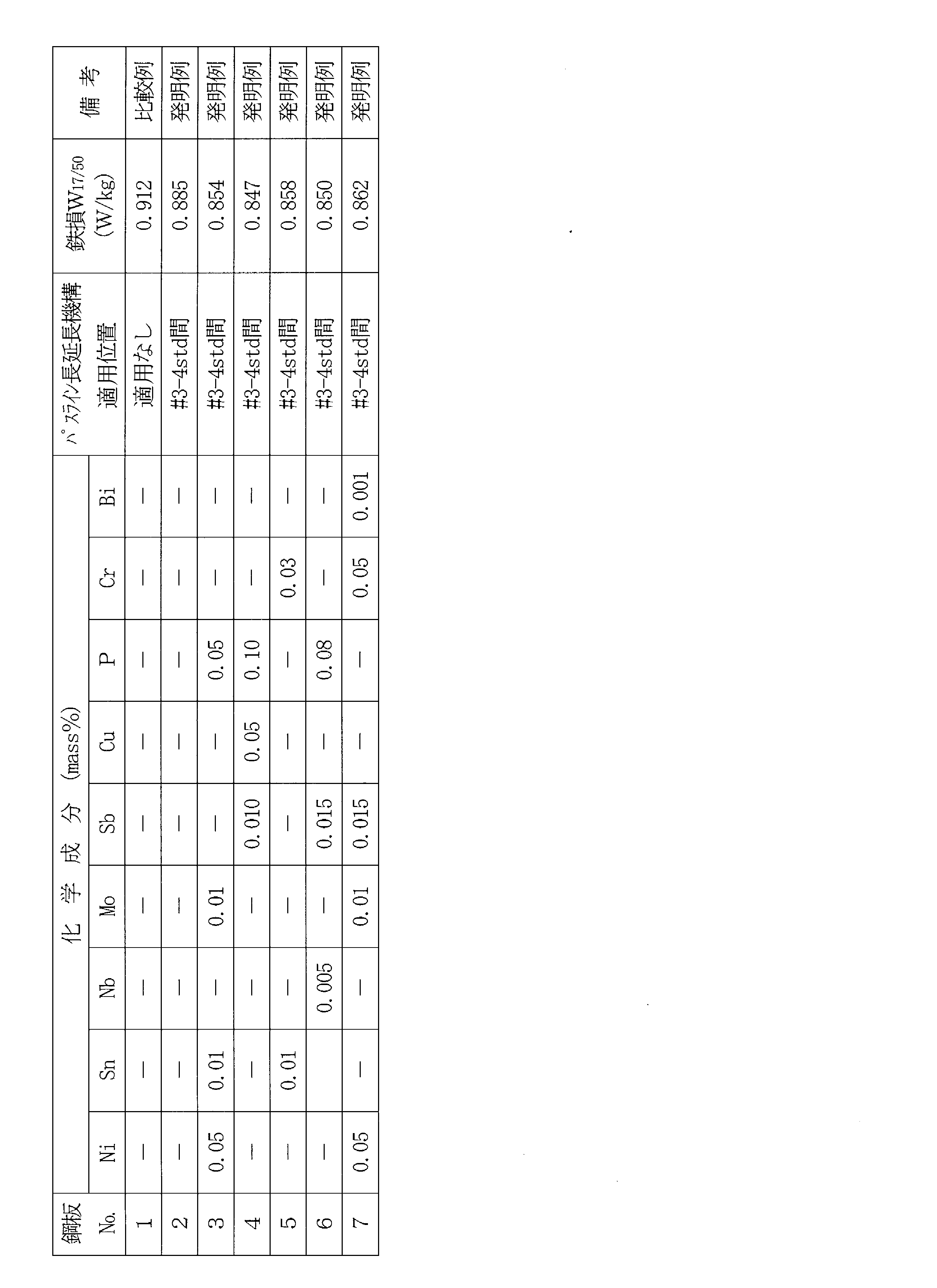
- a steel slab having a component composition not to be heated was reheated to a temperature of 1100 ° C., then hot-rolled into a hot-rolled sheet having a thickness of 2.0 mm, and subjected to hot-rolled sheet annealing at 1000 ° C. ⁇ 60 s.
- the steel sheet after the hot-rolled sheet annealing was descaled, and finally cold-rolled using a four-stand tandem rolling mill having a pass line extending mechanism of the present invention shown in FIG. Finished into a cold rolled sheet of 0.30 mm (total cold rolling reduction: 85%).
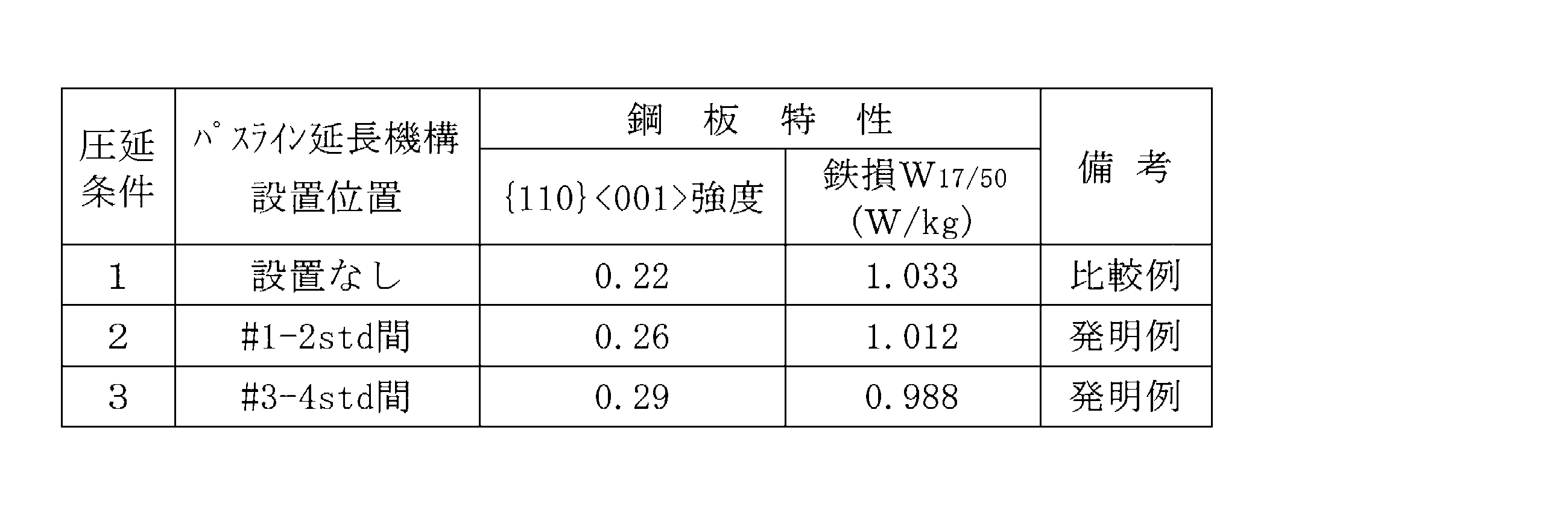
- the final cold rolling is performed under the same rolling conditions 1 as in the related art without using the pass line extending mechanism, and between the # 1-2 stands after rolling the pass line extending mechanism at the # 1 stand at a rolling reduction of 38%.
- the rolling condition 3 applied between the # 3-4 stands after the rolling of the pass line extending mechanism with the total reduction of 78% at the # 1-3 stand and the # 3-3 stand. .
- the length of the pass line was extended to 1.5 times the distance L between stands between stands to which the above-described pass line extending mechanism was applied. Further, under the experimental conditions 1 and 2, the temperature of the steel plate between the stands # 1-2 and between the stands # 3-4 under the experimental condition 3 was controlled to 200 ° C. by controlling the amount of the rolling oil.
- an annealing separator mainly composed of MgO is applied to the steel sheet after the above-mentioned primary recrystallization annealing, and finish annealing is performed to develop secondary recrystallization, and then phosphate-chromate-colloidal silica was applied and baked at a mass ratio of 3: 1: 2, and then subjected to strain relief annealing at 800 ° C for 3 hours. From the rolling direction and the sheet width direction at the center of the sheet width of the steel sheet after the strain relief annealing thus obtained, a test piece having a total mass of 500 g or more having a width of 30 mm and a length of 280 mm was sampled, and subjected to an Epstein test. The loss W 17/50 was measured.
- a steel slab having a component composition consisting of Fe and unavoidable impurities is reheated to a temperature of 1200 ° C., and then hot-rolled into a hot-rolled sheet having a thickness of 2.5 mm. After subjecting the strip to annealing and descaling, the first cold rolling was performed to set the intermediate sheet thickness to 1.5 mm, the intermediate annealing at 1030 ° C.
- the cold-rolled sheet having the final sheet thickness is subjected to primary recrystallization annealing also serving as decarburizing annealing at 850 ° C. ⁇ 40 s in a wet hydrogen atmosphere, and then an annealing separator containing MgO as a main component on the surface of the steel sheet. And then subjected to finish annealing to cause secondary recrystallization, followed by application of an insulating coating containing phosphate-chromate-colloidal silica at a mass ratio of 3: 1: 2, and 850 ° C.
- the total mass of a test piece having a width of 30 mm ⁇ length: 280 mm becomes 500 g or more from the rolling direction and the sheet width direction at the position corresponding to the outer winding of the coil during the finish annealing.
- the iron loss W 17/50 was measured by the Epstein test.
- the technology of the present invention is not limited to the field of grain-oriented electrical steel sheets using an inhibitor-less steel material, and other technologies that require aging between passes or that require an appropriate time between passes
- the present invention can also be suitably used in the field, for example, in the fields of oriented magnetic steel sheets, non-oriented magnetic steel sheets, cold-rolled steel sheets, and the like utilizing inhibitors.
- backup roll 2 work roll 3: fixed roll 4: movable roll S: steel plate L: distance between stands
Landscapes
- Chemical & Material Sciences (AREA)
- Engineering & Computer Science (AREA)
- Mechanical Engineering (AREA)
- Organic Chemistry (AREA)
- Metallurgy (AREA)
- Materials Engineering (AREA)
- Physics & Mathematics (AREA)
- Electromagnetism (AREA)
- Crystallography & Structural Chemistry (AREA)
- Thermal Sciences (AREA)
- Manufacturing & Machinery (AREA)
- Power Engineering (AREA)
- Dispersion Chemistry (AREA)
- Manufacturing Of Steel Electrode Plates (AREA)
- Soft Magnetic Materials (AREA)
Abstract
Description
T≧1.3×L/V ・・・(1)
を満たすよう、該スタンド間の鋼板のパスライン長さを延長して圧延することを特徴とする方向性電磁鋼板の製造方法を提案する。
発明者らは、特に集合組織制御が重要な位置付けをもつ、インヒビター形成成分を含有していない鋼素材を用いた方向性電磁鋼板の製造方法において、タンデム圧延を想定した以下に説明する実験を行い、集合組織の改善に必要な条件を検討した。
<実験>
C:0.050mass%、Si:3.3mass%、Mn:0.04mass%、sol.Al:0.0050mass%を含有し、N:0.0025mass%未満、さらに、S,SeおよびOをそれぞれ0.0050mass%未満含有し、残部がFeおよび不可避的不純物からなる成分組成を有する、インヒビター形成成分を含有していない鋼スラブを1100℃に再加熱した後、熱間圧延して板厚1.8mmの熱延板とし、1000℃×70sの熱延板焼鈍を施した。
この際、1パス目の鋼板供給速度は100mpm、1パス目から5パス目までの各パスの圧下率は30%(一定)とし、各パスにおけるその他の圧延条件は、表1に示したように変化させた。

本発明は、上記の新規な知見に基づき、開発したものである。
C:0.01~0.10mass%
Cは、一次再結晶集合組織を改善するのに有用な元素であり、少なくとも0.01mass%の含有が必要である。一方、C含有量が0.10mass%を超えると、却って一次再結晶集合組織の劣化を招くようになる。よって、C含有量は0.01~0.10mass%の範囲とする。なお、磁気特性を重視する観点から、好ましくは0.01~0.06mass%の範囲である。
Siは、鋼の固有抵抗を高めて鉄損を低減する有用な元素であり、本発明では2.0mass%以上含有させる。一方、Si含有量が4.5mass%を超えると、冷間圧延性が著しく低下する。よって、Si含有量は2.0~4.5mass%の範囲とする。好ましくは2.5~4.0mass%の範囲である。
Mnは、熱間圧延における加工性を向上する効果がある他、一次再結晶焼鈍時の酸化被膜形成を制御し、もって、二次再結晶時のフォルステライト被膜形成を促進する効果を有する有用な元素である。そこで、上記の効果を得る観点から、Mnは0.01mass%以上含有する必要がある。しかし、Mn含有量が0.5mass%を超えると、一次再結晶集合組織が悪化して磁気特性の劣化を招くようになる。よって、Mn含有量は0.01~0.5mass%の範囲とする。好ましくは0.03~0.3mass%の範囲である。
Alは、酸素との親和力が高く、製鋼段階で微量添加することで、鋼中の溶存酸素量を低減し、鉄損特性の劣化につながる酸化物系介在物を低減する効果があるため、sol.Alで0.0020mass%以上含有させる必要がある。しかし、Alは、鋼板表面に緻密な酸化膜を形成し、脱炭を阻害するたるため、sol.Alで0.0100mass%未満に制限する。好ましくはsol.Alで0.0030~0.0090mass%の範囲である。
Nは、本発明においては不要な元素であり、窒化物を形成するNの含有量が0.0080mass%以上になると、粒界偏析や窒化物の形成によって、集合組織が劣化するといった弊害が生じるようになる。さらに、スラブ加熱時にフクレなどの欠陥を生ずる原因ともなる。よって、Nの含有量は0.0080mass%未満に制限する。好ましくは0.0060mass%以下である。
S,SeおよびOは、インヒビターとなる析出物や酸化物を形成する元素であり、それらの元素がそれぞれ0.0050mass%以上になると、スラブ加熱時に粗大化したMnS,MnSe等の析出物や粗大な酸化物が、一次再結晶組織を不均一化するため、二次再結晶の発現が困難となる。よって、S,SeおよびOはいずれも0.0050mass%未満に制限する。好ましくは、それぞれ0.0030mass%以下である。
Ni:0.005~1.50mass%
Niは、熱延板組織の均一性を高めることによって磁気特性を改善する効果があり、上記効果を得るため、0.005mass%以上含有することができる。しかし、Ni含有量が1.50mass%を超えると、二次再結晶が困難となり、磁気特性が劣化する。よって、Niは0.005~1.50mass%の範囲で含有するのが好ましい。より好ましくは0.01~1.0mass%の範囲である。
Snは、二次再結晶焼鈍における鋼板の窒化や酸化を抑制し、良好な結晶方位を有する二次再結晶粒の生成を促進して磁気特性を向上する効果がある。上記効果は0.005mass%以上含有することで得られる。一方、Sn含有量が0.50mass%を超えると、冷間圧延性が低下する。よって、Snは0.005~0.50mass%の範囲で含有するのが好ましい。より好ましくは0.01~0.30mass%の範囲である。
NbおよびMoは、スラブ加熱時のスラブ表面割れの抑制等を介して、熱延時のヘゲ発生を防止する効果がある。上記効果は、Nb含有量が0.0005mass%以上、Mo含有量が0.01mass%以上で得られる。一方、Nb含有量が0.0100mass%、Mo含有量が0.50mass%を超えると、生成する炭化物や窒化物の量が増大し、それらが最終製品まで残留して鉄損劣化を引き起こすようになる。よって、Nbは0.0005~0.0100mass%、および、Moは0.01~0.50mass%の範囲とするのが好ましい。なお、より好ましいMoの範囲は0.01~0.30mass%である。
Sbは、鋼板表面の酸化を抑制する効果があり、また、二次再結晶時に酸化や窒化を抑制するので、良好な結晶方位を有する二次再結晶の成長を促進して、磁気特性を向上する効果もある。上記効果を得るためには0.005mass%以上含有するのが好ましい。一方、0.50mass%を超えて含有すると、冷間圧延性が低下するようになる。よって、Sbは0.005~0.50mass%の範囲で含有するのが好ましい。より好ましくは0.01~0.30mass%の範囲である。
Cuは、Sbと同様、鋼板表面の酸化を抑制する働きがあり、二次再結晶焼鈍時の鋼板表面の酸化を抑制することで、良好な結晶方位を有する二次再結晶の成長を促進して磁気特性を向上する効果がある。上記効果は0.01mass%以上含有することで得られる。しかし、1.50mass%を超えて含有すると、熱間圧延性の低下を招く。よって、Cuは0.01~1.50mass%の範囲で含有するのが好ましい。より好ましくは0.01~1.0mass%の範囲である。
Pは、脱炭焼鈍時のサブスケール形成を介してフォルステライト被膜の形成を安定化する働きがある。上記効果は0.005mass%以上の含有により得られる。一方、Pの含有量が0.150mass%を超えると冷間圧延性が低下するようになる。よって、Pは0.005~0.150mass%の範囲で含有するのが好ましい。より好ましくは0.01~0.10mass%の範囲である。
Crは、脱炭焼鈍時のサブスケール形成を介してフォルステライト被膜の形成を安定化する働きがある。上記効果は0.01mass%以上の含有により得られる。一方、Cr含有量が1.50mass%を超えると、二次再結晶が困難となり、磁気特性が劣化する。よって、Crは0.01~1.50mass%の範囲で含有するのが好ましい。より好ましくは0.01~1.0mass%の範囲である。
Biは、磁気特性の改善に有効な元素であり、必要に応じて含有することができる。しかし、上記効果は0.0005mass%未満では小さく、一方、0.05mass%を超えると、フォルステライト被膜形成を阻害するようになる。よって、Biは0.0005~0.05mass%の範囲で含有するのが好ましい。より好ましくは0.001~0.03mass%の範囲である。
まず、上記に説明した本発明に適合する成分組成に調整した鋼を、常法の精錬プロセスで溶製した後、連続鋳造法あるいは造塊-分塊圧延法で鋼素材(スラブ)とする。
次いで、上記スラブを再加熱した後、あるいは、再加熱することなく、熱間圧延に供する。なお、スラブを再加熱する場合には、再加熱温度は1000~1300℃の範囲とするのが好ましい。インヒビター形成成分をほとんど含まない鋼素材を用いる本発明では、1300℃を超えるスラブ加熱は、技術的意味はなく、コストアップとなるだけである。一方、1000℃未満では、熱間圧延の負荷が増大し、圧延が困難となる。なお、熱間圧延における圧延条件は、常法に準じて行えばよく、特に制限はない。
この際、上記最終冷間圧延は、パスライン延長機構を適用しない従来と同じ圧延条件1、パスライン延長機構を#1スタンドで圧下率38%の圧延を行った後の#1-2スタンド間に適用した圧延条件2、および、パスライン延長機構を#1-3スタンドで総圧下率78%の圧延を行った後の#3-4スタンド間に適用した圧延条件3の3条件で行った。なお、上記パスライン延長機構を適用したスタンド間では、パスライン長さをスタンド間距離Lの1.5倍に延長した。また、上記実験条件1と2においては#1-2スタンド間、また、実験条件3においては#3-4スタンド間の鋼板温度を圧延油の量を制御して200℃に制御した。
斯くして得た、歪取焼鈍後の鋼板の板幅中央部の圧延方向および板幅方向から、幅:30mm×長さ:280mmの試験片を総質量で500g以上採取し、エプスタイン試験により鉄損W17/50を測定した。
この際、最終冷間圧延における各スタンドの圧下率は、38%(一定)に設定するとともに、#3-4スタンド間に、前述した図2に示したパスライン延長機構を適用し、#3-4スタンド間の鋼板のパスライン長さを、スタンド間距離Lの1.5倍に延長して圧延を行った。このとき、いずれの条件も、#3スタンド出側の鋼板温度が200℃を超えるように圧延油の量を制限し、さらに、パスライン延長機構を設置した条件では、#3-4スタンド間に設置したパスライン変更用の可動ロールの一つを加熱機能を有するものとし、鋼板温度を250℃に加熱した。
2:ワークロール
3:固定ロール
4:可動ロール
S:鋼板
L:スタンド間距離
Claims (8)
- C:0.01~0.10mass%、Si:2.0~4.5mass%、Mn:0.01~0.5mass%、sol.Al:0.0020mass%以上0.0100mass%未満、N:0.0080mass%未満含有し、さらに、S,SeおよびOをそれぞれ0.0050mass%未満含有し、残部がFeおよび不可避的不純物からなる鋼スラブを1300℃以下の温度に再加熱した後、熱間圧延し、1回の冷間圧延または中間焼鈍を挟む2回以上の冷間圧延して最終板厚の冷延板とした後、脱炭焼鈍を兼ねた一次再結晶焼鈍し、鋼板表面に焼鈍分離剤を塗布した後、二次再結晶させる仕上焼鈍を施す方向性電磁鋼板の製造方法において、
上記最終板厚に冷間圧延する最終冷間圧延は、タンデム圧延機を用いて、総圧下率80%以上、かつ、少なくとも一つのスタンド間の板温が150~280℃となるよう圧延するとともに、
上記スタンド間の距離をL(m)、該スタンド間を通過する鋼板速度をV(mpm)、該スタンド間を鋼板が通過するパス時間をT(min)としたとき、上記スタンド間のパス時間Tが下記(1)式を満たすよう、該スタンド間の鋼板のパスライン長さを延長して圧延することを特徴とする方向性電磁鋼板の製造方法。
記
T≧1.3×L/V ・・・(1) - 上記スタンド間の鋼板のパスライン長さの延長を、総圧下率が66%以上のスタンド間において行うことを特徴とする請求項1に記載の方向性電磁鋼板の製造方法。
- 上記鋼スラブは、さらに、Ni:0.005~1.50mass%、Sn:0.005~0.50mass%、Nb:0.0005~0.0100mass%、Mo:0.01~0.50mass%、Sb:0.005~0.50mass%、Cu:0.01~1.50mass%、P:0.005~0.150mass%、Cr:0.01~1.50mass%およびBi:0.0005~0.05mass%のうちから選ばれる1種または2種以上を含有することを特徴とする請求項1または2に記載の方向性電磁鋼板の製造方法。
- 鋼板を最終板厚に冷間圧延する、複数のスタンドからなるタンデム圧延機において、
いずれか1以上のスタンド間に、スタンド間の鋼板のパスライン長さを、スタンド間距離よりも長くするパスライン延長機構を設けてなるとともに、パスラインを変更する可動ロールが少なくとも2個以上あり、かつ、それらの可動ロールのうちの少なくとも1個が基準の水平パスラインに対して他のロールと上下対極の位置に配置されてなることを特徴とする冷間圧延設備。 - 上記冷間圧延設備は、上記スタンド間に配置したパスラインを変更する可動ロールのいずれか1以上が加熱機能を備えてなることを特徴とする請求項4に記載の冷間圧延設備。
- 上記パスライン延長機構は、スタンド間の鋼板のパスライン長さを、スタンド間距離に対して1.3倍以上に延長可能であることを特徴とする請求項4または5に記載の冷間圧延設備。
- 上記パスライン延長機構を、総圧下率が66%以上となるスタンド間に設置してなることを特徴とする請求項4~6のいずれか1項に記載の冷間圧延設備。
- 圧延する鋼板が電磁鋼板であることを特徴とする請求項4~7のいずれか1項に記載の冷間圧延設備。
Priority Applications (7)
| Application Number | Priority Date | Filing Date | Title |
|---|---|---|---|
| RU2021111916A RU2769149C1 (ru) | 2018-09-28 | 2019-09-26 | Способ изготовления листа из текстурированной электротехнической стали и стан холодной прокатки |
| JP2019563638A JP6721135B1 (ja) | 2018-09-28 | 2019-09-26 | 方向性電磁鋼板の製造方法および冷間圧延設備 |
| US17/279,194 US12037654B2 (en) | 2018-09-28 | 2019-09-26 | Method for producing grain-oriented electrical steel sheet and cold-rolling facility |
| CN201980063014.9A CN112752623B (zh) | 2018-09-28 | 2019-09-26 | 方向性电磁钢板的制造方法和冷轧设备 |
| KR1020217007131A KR102503902B1 (ko) | 2018-09-28 | 2019-09-26 | 방향성 전기 강판의 제조 방법 및 냉간 압연 설비 |
| EP19865374.3A EP3854891A4 (en) | 2018-09-28 | 2019-09-26 | PROCESS FOR THE PRODUCTION OF AN ELECTROMAGNETIC ORIENTED GRAIN STEEL SHEET AND COLD ROLLING EQUIPMENT |
| US18/735,904 US12344909B2 (en) | 2018-09-28 | 2024-06-06 | Method for producing grain-oriented electrical steel sheet and cold-rolling facility |
Applications Claiming Priority (2)
| Application Number | Priority Date | Filing Date | Title |
|---|---|---|---|
| JP2018183898 | 2018-09-28 | ||
| JP2018-183898 | 2018-09-28 |
Related Child Applications (2)
| Application Number | Title | Priority Date | Filing Date |
|---|---|---|---|
| US17/279,194 A-371-Of-International US12037654B2 (en) | 2018-09-28 | 2019-09-26 | Method for producing grain-oriented electrical steel sheet and cold-rolling facility |
| US18/735,904 Division US12344909B2 (en) | 2018-09-28 | 2024-06-06 | Method for producing grain-oriented electrical steel sheet and cold-rolling facility |
Publications (1)
| Publication Number | Publication Date |
|---|---|
| WO2020067236A1 true WO2020067236A1 (ja) | 2020-04-02 |
Family
ID=69950666
Family Applications (1)
| Application Number | Title | Priority Date | Filing Date |
|---|---|---|---|
| PCT/JP2019/037752 Ceased WO2020067236A1 (ja) | 2018-09-28 | 2019-09-26 | 方向性電磁鋼板の製造方法および冷間圧延設備 |
Country Status (7)
| Country | Link |
|---|---|
| US (2) | US12037654B2 (ja) |
| EP (1) | EP3854891A4 (ja) |
| JP (1) | JP6721135B1 (ja) |
| KR (1) | KR102503902B1 (ja) |
| CN (1) | CN112752623B (ja) |
| RU (1) | RU2769149C1 (ja) |
| WO (1) | WO2020067236A1 (ja) |
Cited By (5)
| Publication number | Priority date | Publication date | Assignee | Title |
|---|---|---|---|---|
| WO2023277169A1 (ja) * | 2021-06-30 | 2023-01-05 | Jfeスチール株式会社 | 方向性電磁鋼板の製造方法及び方向性電磁鋼板製造用圧延設備 |
| WO2023277170A1 (ja) * | 2021-06-30 | 2023-01-05 | Jfeスチール株式会社 | 方向性電磁鋼板の製造方法及び方向性電磁鋼板製造用圧延設備 |
| KR20230018452A (ko) * | 2020-06-30 | 2023-02-07 | 제이에프이 스틸 가부시키가이샤 | 방향성 전기 강판의 제조 방법 및 설비열 |
| EP4265349A4 (en) * | 2021-01-28 | 2024-10-16 | JFE Steel Corporation | METHOD FOR PRODUCING AN ORIENTATED ELECTROMAGNETIC STEEL SHEET AND ROLLING EQUIPMENT FOR PRODUCING AN ELECTROMAGNETIC STEEL SHEET |
| RU2855672C1 (ru) * | 2025-07-02 | 2026-02-02 | ПАО "Новолипецкий металлургический комбинат" | Способ получения холоднокатаного проката из электротехнической стали |
Citations (9)
| Publication number | Priority date | Publication date | Assignee | Title |
|---|---|---|---|---|
| JPS4839338A (ja) | 1971-09-27 | 1973-06-09 | ||
| JPS5016610A (ja) | 1973-06-18 | 1975-02-21 | ||
| JPS5079442A (ja) | 1973-11-17 | 1975-06-27 | ||
| JPS5413846A (en) | 1977-07-01 | 1979-02-01 | Lucas Industries Ltd | Starting motor for internal combustion engine |
| JPS5429182A (en) | 1977-12-15 | 1979-03-05 | Ntn Toyo Bearing Co Ltd | Device for forming pocket bores in ring |
| JPH01215925A (ja) | 1988-02-25 | 1989-08-29 | Nippon Steel Corp | 一方向性電磁鋼板の冷間圧延方法 |
| JPH08253816A (ja) | 1995-03-15 | 1996-10-01 | Nippon Steel Corp | 超高磁束密度一方向性電磁鋼板の製造方法 |
| JP2000129356A (ja) | 1998-10-28 | 2000-05-09 | Kawasaki Steel Corp | 方向性電磁鋼板の製造方法 |
| JP2006095544A (ja) * | 2004-09-28 | 2006-04-13 | Jfe Steel Kk | 鋼帯の冷間圧延設備および鋼帯の冷間圧延方法 |
Family Cites Families (15)
| Publication number | Priority date | Publication date | Assignee | Title |
|---|---|---|---|---|
| US4098929A (en) | 1973-11-12 | 1978-07-04 | Chrysler Corporation | Method for improved parting from hot surfaces |
| JPS5365245A (en) * | 1976-11-24 | 1978-06-10 | Kobe Steel Ltd | Metal strip rolling |
| US6309473B1 (en) | 1998-10-09 | 2001-10-30 | Kawasaki Steel Corporation | Method of making grain-oriented magnetic steel sheet having low iron loss |
| JP4258157B2 (ja) | 2002-03-05 | 2009-04-30 | Jfeスチール株式会社 | 方向性電磁鋼板の製造方法 |
| DE10234109A1 (de) | 2002-07-26 | 2004-02-05 | Sms Demag Ag | Verfahren und Vorrichtung zur kontinuierlichen Herstellung metallischer Bänder |
| EP1963958B1 (en) | 2005-12-21 | 2019-04-24 | Digimarc Corporation | Rules driven pan id metadata routing system and network |
| KR101120125B1 (ko) | 2007-04-24 | 2012-03-22 | 신닛뽄세이테쯔 카부시키카이샤 | 일방향성 전자강판의 제조 방법 |
| JP5079422B2 (ja) | 2007-08-21 | 2012-11-21 | 株式会社セイコーアイ・インフォテック | インクジェット印刷装置、および印刷方法 |
| JP4839338B2 (ja) | 2008-05-30 | 2011-12-21 | 株式会社日立製作所 | 超音波探傷装置及び方法 |
| WO2010047214A1 (ja) | 2008-10-24 | 2010-04-29 | 株式会社村田製作所 | 無線icデバイス |
| JP5413846B2 (ja) | 2010-03-09 | 2014-02-12 | 公立大学法人首都大学東京 | 二足歩行ロボット |
| JP5835557B2 (ja) * | 2011-02-17 | 2015-12-24 | Jfeスチール株式会社 | 方向性電磁鋼板の製造方法 |
| JP5672273B2 (ja) * | 2012-07-26 | 2015-02-18 | Jfeスチール株式会社 | 方向性電磁鋼板の製造方法 |
| JP5831435B2 (ja) * | 2012-12-11 | 2015-12-09 | Jfeスチール株式会社 | 磁気特性に優れた方向性電磁鋼板の製造方法 |
| JP5846390B2 (ja) * | 2013-03-06 | 2016-01-20 | Jfeスチール株式会社 | 方向性電磁鋼板の製造方法 |
-
2019
- 2019-09-26 RU RU2021111916A patent/RU2769149C1/ru active
- 2019-09-26 JP JP2019563638A patent/JP6721135B1/ja active Active
- 2019-09-26 CN CN201980063014.9A patent/CN112752623B/zh active Active
- 2019-09-26 EP EP19865374.3A patent/EP3854891A4/en active Pending
- 2019-09-26 US US17/279,194 patent/US12037654B2/en active Active
- 2019-09-26 WO PCT/JP2019/037752 patent/WO2020067236A1/ja not_active Ceased
- 2019-09-26 KR KR1020217007131A patent/KR102503902B1/ko active Active
-
2024
- 2024-06-06 US US18/735,904 patent/US12344909B2/en active Active
Patent Citations (9)
| Publication number | Priority date | Publication date | Assignee | Title |
|---|---|---|---|---|
| JPS4839338A (ja) | 1971-09-27 | 1973-06-09 | ||
| JPS5016610A (ja) | 1973-06-18 | 1975-02-21 | ||
| JPS5079442A (ja) | 1973-11-17 | 1975-06-27 | ||
| JPS5413846A (en) | 1977-07-01 | 1979-02-01 | Lucas Industries Ltd | Starting motor for internal combustion engine |
| JPS5429182A (en) | 1977-12-15 | 1979-03-05 | Ntn Toyo Bearing Co Ltd | Device for forming pocket bores in ring |
| JPH01215925A (ja) | 1988-02-25 | 1989-08-29 | Nippon Steel Corp | 一方向性電磁鋼板の冷間圧延方法 |
| JPH08253816A (ja) | 1995-03-15 | 1996-10-01 | Nippon Steel Corp | 超高磁束密度一方向性電磁鋼板の製造方法 |
| JP2000129356A (ja) | 1998-10-28 | 2000-05-09 | Kawasaki Steel Corp | 方向性電磁鋼板の製造方法 |
| JP2006095544A (ja) * | 2004-09-28 | 2006-04-13 | Jfe Steel Kk | 鋼帯の冷間圧延設備および鋼帯の冷間圧延方法 |
Non-Patent Citations (1)
| Title |
|---|
| See also references of EP3854891A4 |
Cited By (13)
| Publication number | Priority date | Publication date | Assignee | Title |
|---|---|---|---|---|
| KR20230018452A (ko) * | 2020-06-30 | 2023-02-07 | 제이에프이 스틸 가부시키가이샤 | 방향성 전기 강판의 제조 방법 및 설비열 |
| US12569897B2 (en) | 2020-06-30 | 2026-03-10 | Jfe Steel Corporation | Production method for grain-oriented electrical steel sheet, and production line |
| KR102835139B1 (ko) | 2020-06-30 | 2025-07-17 | 제이에프이 스틸 가부시키가이샤 | 방향성 전기 강판의 제조 방법 및 설비열 |
| EP4159337A4 (en) * | 2020-06-30 | 2024-07-31 | JFE Steel Corporation | METHOD FOR PRODUCING A GRAIN-ORIENTED ELECTROMAGNETIC STEEL SHEET AND EQUIPMENT LINE |
| EP4265349A4 (en) * | 2021-01-28 | 2024-10-16 | JFE Steel Corporation | METHOD FOR PRODUCING AN ORIENTATED ELECTROMAGNETIC STEEL SHEET AND ROLLING EQUIPMENT FOR PRODUCING AN ELECTROMAGNETIC STEEL SHEET |
| JPWO2023277170A1 (ja) * | 2021-06-30 | 2023-01-05 | ||
| WO2023277169A1 (ja) * | 2021-06-30 | 2023-01-05 | Jfeスチール株式会社 | 方向性電磁鋼板の製造方法及び方向性電磁鋼板製造用圧延設備 |
| JP7616242B2 (ja) | 2021-06-30 | 2025-01-17 | Jfeスチール株式会社 | 方向性電磁鋼板の製造方法及び方向性電磁鋼板製造用圧延設備 |
| JP7616243B2 (ja) | 2021-06-30 | 2025-01-17 | Jfeスチール株式会社 | 方向性電磁鋼板の製造方法及び方向性電磁鋼板製造用圧延設備 |
| WO2023277170A1 (ja) * | 2021-06-30 | 2023-01-05 | Jfeスチール株式会社 | 方向性電磁鋼板の製造方法及び方向性電磁鋼板製造用圧延設備 |
| EP4357468A4 (en) * | 2021-06-30 | 2025-07-23 | Jfe Steel Corp | METHOD FOR MANUFACTURING GRAIN-ORIENTED ELECTROMAGNETIC STEEL SHEET AND ROLLING EQUIPMENT FOR MANUFACTURING GRAIN-ORIENTED ELECTROMAGNETIC STEEL SHEET |
| JPWO2023277169A1 (ja) * | 2021-06-30 | 2023-01-05 | ||
| RU2855672C1 (ru) * | 2025-07-02 | 2026-02-02 | ПАО "Новолипецкий металлургический комбинат" | Способ получения холоднокатаного проката из электротехнической стали |
Also Published As
| Publication number | Publication date |
|---|---|
| US20220033921A1 (en) | 2022-02-03 |
| US12037654B2 (en) | 2024-07-16 |
| CN112752623B (zh) | 2023-06-16 |
| EP3854891A1 (en) | 2021-07-28 |
| KR20210042368A (ko) | 2021-04-19 |
| US12344909B2 (en) | 2025-07-01 |
| JPWO2020067236A1 (ja) | 2021-02-15 |
| JP6721135B1 (ja) | 2020-07-08 |
| US20240327942A1 (en) | 2024-10-03 |
| RU2769149C1 (ru) | 2022-03-28 |
| EP3854891A4 (en) | 2021-07-28 |
| CN112752623A (zh) | 2021-05-04 |
| KR102503902B1 (ko) | 2023-02-27 |
Similar Documents
| Publication | Publication Date | Title |
|---|---|---|
| KR102260531B1 (ko) | 방향성 전기 강판용 열연 강판 및 그 제조 방법, 그리고 방향성 전기 강판의 제조 방법 | |
| US12344909B2 (en) | Method for producing grain-oriented electrical steel sheet and cold-rolling facility | |
| KR102925367B1 (ko) | 방향성 전기 강판의 제조 방법 및 전기 강판 제조용 압연 설비 | |
| US20250163529A1 (en) | Method for producing grain-oriented electrical steel sheet | |
| KR102835138B1 (ko) | 방향성 전기 강판의 제조 방법 및 설비열 | |
| JP2020056105A (ja) | 方向性電磁鋼板の製造方法 | |
| US20260085372A1 (en) | Method for producing grain-oriented electrical steel sheet, and induction heating device | |
| JP3849146B2 (ja) | 一方向性けい素鋼板の製造方法 | |
| US12569897B2 (en) | Production method for grain-oriented electrical steel sheet, and production line | |
| EP4575010A1 (en) | Method for producing grain-oriented electromagnetic steel sheet, and induction heater | |
| US12480176B2 (en) | Method of manufacturing grain-oriented electrical steel sheet | |
| EP4729639A1 (en) | Method for manufacturing oriented electromagnetic steel sheet, and induction heating device | |
| JP3536304B2 (ja) | 表面性状に優れ、磁気特性の安定した方向性けい素鋼板の製造方法 | |
| EP4729640A1 (en) | Method for producing grain-oriented electrical steel sheet, and induction heating device | |
| WO2025154576A1 (ja) | 方向性電磁鋼板の冷間圧延方法および製造方法ならびに冷間圧延設備列 | |
| JP2647323B2 (ja) | 低い鉄損をもつ一方向性電磁鋼板の製造方法 | |
| WO2025154575A1 (ja) | 方向性電磁鋼板の冷間圧延方法および製造方法ならびに冷間圧延設備列 | |
| JP3903494B2 (ja) | 電磁鋼板の製造方法 | |
| JP2023116341A (ja) | 方向性電磁鋼板の製造方法 | |
| JPH1180835A (ja) | 磁束密度が高く、鉄損が極めて低い方向性電磁鋼板の 製造方法 | |
| JPH10280042A (ja) | コイル長手方向の磁気特性の安定した方向性電磁鋼板の製造方法 |
Legal Events
| Date | Code | Title | Description |
|---|---|---|---|
| ENP | Entry into the national phase |
Ref document number: 2019563638 Country of ref document: JP Kind code of ref document: A |
|
| 121 | Ep: the epo has been informed by wipo that ep was designated in this application |
Ref document number: 19865374 Country of ref document: EP Kind code of ref document: A1 |
|
| ENP | Entry into the national phase |
Ref document number: 20217007131 Country of ref document: KR Kind code of ref document: A |
|
| NENP | Non-entry into the national phase |
Ref country code: DE |
|
| ENP | Entry into the national phase |
Ref document number: 2019865374 Country of ref document: EP Effective date: 20210423 |