WO2020071510A1 - Dispositif de mesure de poussière et procédé de mesure de poussière - Google Patents
Dispositif de mesure de poussière et procédé de mesure de poussièreInfo
- Publication number
- WO2020071510A1 WO2020071510A1 PCT/JP2019/039202 JP2019039202W WO2020071510A1 WO 2020071510 A1 WO2020071510 A1 WO 2020071510A1 JP 2019039202 W JP2019039202 W JP 2019039202W WO 2020071510 A1 WO2020071510 A1 WO 2020071510A1
- Authority
- WO
- WIPO (PCT)
- Prior art keywords
- dust
- brake
- substance
- thin film
- collecting plate
- Prior art date
- Legal status (The legal status is an assumption and is not a legal conclusion. Google has not performed a legal analysis and makes no representation as to the accuracy of the status listed.)
- Ceased
Links
Images



Classifications
-
- G—PHYSICS
- G01—MEASURING; TESTING
- G01N—INVESTIGATING OR ANALYSING MATERIALS BY DETERMINING THEIR CHEMICAL OR PHYSICAL PROPERTIES
- G01N15/00—Investigating characteristics of particles; Investigating permeability, pore-volume or surface-area of porous materials
- G01N15/02—Investigating particle size or size distribution
- G01N15/0205—Investigating particle size or size distribution by optical means
- G01N15/0227—Investigating particle size or size distribution by optical means using imaging; using holography
-
- G—PHYSICS
- G01—MEASURING; TESTING
- G01N—INVESTIGATING OR ANALYSING MATERIALS BY DETERMINING THEIR CHEMICAL OR PHYSICAL PROPERTIES
- G01N1/00—Sampling; Preparing specimens for investigation
- G01N1/02—Devices for withdrawing samples
- G01N1/22—Devices for withdrawing samples in the gaseous state
- G01N1/2202—Devices for withdrawing samples in the gaseous state involving separation of sample components during sampling
- G01N1/2208—Devices for withdrawing samples in the gaseous state involving separation of sample components during sampling with impactors
-
- G—PHYSICS
- G01—MEASURING; TESTING
- G01N—INVESTIGATING OR ANALYSING MATERIALS BY DETERMINING THEIR CHEMICAL OR PHYSICAL PROPERTIES
- G01N15/00—Investigating characteristics of particles; Investigating permeability, pore-volume or surface-area of porous materials
- G01N15/02—Investigating particle size or size distribution
- G01N15/0255—Investigating particle size or size distribution with mechanical, e.g. inertial, classification, and investigation of sorted collections
-
- G—PHYSICS
- G01—MEASURING; TESTING
- G01N—INVESTIGATING OR ANALYSING MATERIALS BY DETERMINING THEIR CHEMICAL OR PHYSICAL PROPERTIES
- G01N15/00—Investigating characteristics of particles; Investigating permeability, pore-volume or surface-area of porous materials
- G01N15/10—Investigating individual particles
- G01N15/14—Optical investigation techniques, e.g. flow cytometry
- G01N15/1429—Signal processing
- G01N15/1433—Signal processing using image recognition
-
- G—PHYSICS
- G01—MEASURING; TESTING
- G01N—INVESTIGATING OR ANALYSING MATERIALS BY DETERMINING THEIR CHEMICAL OR PHYSICAL PROPERTIES
- G01N15/00—Investigating characteristics of particles; Investigating permeability, pore-volume or surface-area of porous materials
- G01N2015/0042—Investigating dispersion of solids
- G01N2015/0046—Investigating dispersion of solids in gas, e.g. smoke
-
- G—PHYSICS
- G01—MEASURING; TESTING
- G01N—INVESTIGATING OR ANALYSING MATERIALS BY DETERMINING THEIR CHEMICAL OR PHYSICAL PROPERTIES
- G01N15/00—Investigating characteristics of particles; Investigating permeability, pore-volume or surface-area of porous materials
- G01N15/02—Investigating particle size or size distribution
- G01N15/0255—Investigating particle size or size distribution with mechanical, e.g. inertial, classification, and investigation of sorted collections
- G01N2015/0261—Investigating particle size or size distribution with mechanical, e.g. inertial, classification, and investigation of sorted collections using impactors
-
- G—PHYSICS
- G01—MEASURING; TESTING
- G01N—INVESTIGATING OR ANALYSING MATERIALS BY DETERMINING THEIR CHEMICAL OR PHYSICAL PROPERTIES
- G01N15/00—Investigating characteristics of particles; Investigating permeability, pore-volume or surface-area of porous materials
- G01N15/02—Investigating particle size or size distribution
- G01N2015/0288—Sorting the particles
-
- G—PHYSICS
- G01—MEASURING; TESTING
- G01N—INVESTIGATING OR ANALYSING MATERIALS BY DETERMINING THEIR CHEMICAL OR PHYSICAL PROPERTIES
- G01N15/00—Investigating characteristics of particles; Investigating permeability, pore-volume or surface-area of porous materials
- G01N15/02—Investigating particle size or size distribution
- G01N2015/0294—Particle shape
-
- G—PHYSICS
- G01—MEASURING; TESTING
- G01N—INVESTIGATING OR ANALYSING MATERIALS BY DETERMINING THEIR CHEMICAL OR PHYSICAL PROPERTIES
- G01N15/00—Investigating characteristics of particles; Investigating permeability, pore-volume or surface-area of porous materials
- G01N15/10—Investigating individual particles
- G01N15/14—Optical investigation techniques, e.g. flow cytometry
- G01N2015/1493—Particle size
-
- G—PHYSICS
- G01—MEASURING; TESTING
- G01N—INVESTIGATING OR ANALYSING MATERIALS BY DETERMINING THEIR CHEMICAL OR PHYSICAL PROPERTIES
- G01N15/00—Investigating characteristics of particles; Investigating permeability, pore-volume or surface-area of porous materials
- G01N15/10—Investigating individual particles
- G01N15/14—Optical investigation techniques, e.g. flow cytometry
- G01N2015/1497—Particle shape
-
- G—PHYSICS
- G01—MEASURING; TESTING
- G01N—INVESTIGATING OR ANALYSING MATERIALS BY DETERMINING THEIR CHEMICAL OR PHYSICAL PROPERTIES
- G01N23/00—Investigating or analysing materials by the use of wave or particle radiation, e.g. X-rays or neutrons, not covered by groups G01N3/00 – G01N17/00, G01N21/00 or G01N22/00
- G01N23/22—Investigating or analysing materials by the use of wave or particle radiation, e.g. X-rays or neutrons, not covered by groups G01N3/00 – G01N17/00, G01N21/00 or G01N22/00 by measuring secondary emission from the material
- G01N23/225—Investigating or analysing materials by the use of wave or particle radiation, e.g. X-rays or neutrons, not covered by groups G01N3/00 – G01N17/00, G01N21/00 or G01N22/00 by measuring secondary emission from the material using electron or ion
- G01N23/2251—Investigating or analysing materials by the use of wave or particle radiation, e.g. X-rays or neutrons, not covered by groups G01N3/00 – G01N17/00, G01N21/00 or G01N22/00 by measuring secondary emission from the material using electron or ion using incident electron beams, e.g. scanning electron microscopy [SEM]
Definitions
- the present invention relates to a dust measuring device and a dust measuring method for collecting and measuring the dust from a gas containing dust generated by a friction material generating a braking force.
- a brake device such as a disc brake or a drum brake mounted on an automobile or the like operates
- wear powder is generated due to wear of a brake pad and a rotor. Therefore, for example, the actual braking state, behavior, and abrasion state of each member in the brake device are reflected on the shape, size, amount of abrasion powder generation, and the like of each abrasion powder.
- the brake device can be improved and its performance can be improved.
- Patent Document 1 shows a technique for improving the operation rate, productivity, and classification accuracy of an airflow classifier used in the production of fine particle toner, in which fusion due to collision of the material to be classified hardly occurs. Further, an airflow classifier having a composite plating film containing fine particles dispersed therein is provided on the surface of a member in the airflow classifier where particles of the material to be classified collide. In addition, a plurality of classification exhaust passages 7, 8 and 9 branched by the classification edges 2 and 3 are opened on the outlet side, and the inlet / outlet passages 11 and 12 are opened on the inlet side.
- Airflow forming means for generating an airflow flowing from the air flow paths 11 and 12 to the respective classification exhaust flow paths 7, 8 and 9, and pressure-feeding and injecting the raw material to be classified 15 into the raw material selection chamber 14 using a compressed gas.
- An exhaust flow path for each classification is provided with a raw material supply nozzle 16, and the particles of the raw material to be classified 15, which are pressure-fed and injected into the raw material separation chamber 14, are scattered and descended in a curved line corresponding to the particle diameter by the Coanda effect.
- category which classifies into 7, 8 and 9 is shown.
- the particle collecting device of Patent Document 2 performs the evaluation of the number, the analysis of the shape, the component, and the like even when the dust is collected in a place where the floating dust is small, such as in a clean room, and the size of an arbitrary size.
- 3 illustrates a technique for enabling the use of an impact plate. Further, the particle collecting device of Patent Document 2 uses a clean mirror-finished collision plate.
- particles such as dust that have been collided with a collision plate as described in Patent Document 2 can be observed using, for example, a scanning electron microscope (SEM). That is, the observer can visually grasp the shape, size, material, and the like of the particles from the image obtained by the scanning electron microscope.
- SEM scanning electron microscope
- the wear powder generated from the brake device is very small, on the order of submicron, and contains components of various materials. Therefore, it is actually difficult to observe the wear powder with a scanning electron microscope. Specifically, it may be difficult to distinguish the unevenness on the surface of the collecting plate that has collected the abrasion powder from the abrasion powder. Further, due to the commonality of the materials, the outer shape of each wear powder material or the boundary between the wear powder and the collecting plate, that is, the contour shape of the wear powder may be unclear. Further, when the surface of the collecting plate is plated, the shape of the abrasion powder and the like are hardly visually recognized due to the influence of the background material behind the film formed on the surface of the collecting plate. There are cases.
- the present invention has been made in view of the above-described circumstances, and an object of the present invention is to provide a dust measuring device and a dust measuring method that allow easy observation of wear powder generated from a brake device.
- a dust measuring device and a dust measuring method are characterized by the following (1) to (7).
- a dust measuring device including a collecting plate arranged at a position where gas containing dust generated by a friction material can collide, and measuring the dust collected by the collecting plate by inertia force of the dust. So, A first substance constituting at least a surface of the collection board is different from a material constituting a component of a second substance contained in the dust to be measured. Dust measuring device.
- the first substance includes any one of nickel, chromium, and cobalt;
- the collecting board has a base material and a thin film formed on a surface portion of the base material;
- the thin film is composed of the first substance;
- the thickness of the thin film has a predetermined size or more necessary to reduce the influence of the base material on the dust in the observation by the scanning electron microscope,
- the dust measuring device according to the above (3).
- a dust measurement method for measuring dust generated by a friction material A first substance constituting at least the surface against which the dust to be measured collides is provided with a collecting plate different from a material constituting a component contained in the second substance contained in the dust, Placing the collecting plate at a position where gas containing dust to be measured can collide, A gas containing dust generated by a friction material that generates a braking force is introduced into the vicinity of the collecting plate, Collecting the dust with the collection board by inertia force of the dust, Dust measurement method.
- the first substance includes any one of nickel, chromium, and cobalt;
- the dust measurement method according to the above (5) is the first substance includes any one of nickel, chromium, and cobalt.
- the thin film is composed of the first substance, The dust measurement method according to the above (5) or (6).
- the dust measuring device having the above configuration (1), since the material of the first substance is different from the material of the second substance, it is easy to distinguish them, and the measurement of the dust to be measured can be performed with high accuracy.
- the material constituting the first substance is different from the material constituting the friction material or the rotor of the general brake device, and therefore, the first material is not included in the dust to be measured. It is easy to distinguish between the two components.
- the material constituting the first substance can easily reduce the content of impurities, and the component contained in the second substance can be easily distinguished from the impurities.
- the base material of the collector is covered with a thin film (thickness that does not affect the observation by the electron microscope), so the degree of freedom of the material constituting the base material is increased. Increase. Therefore, the thin film is formed of the material constituting the first substance while sufficiently securing the strength of the collecting plate by the base material, and therefore, the thin film can be distinguished from the component of the second substance contained in the dust to be measured. Easy.
- the dust measuring device of the above configuration (4) even if the material of the base material is the same as the component of the second substance contained in the dust to be measured, the influence of the base material present on the back side of the thin film The dust can be observed with a scanning electron microscope without being affected by the dust. Therefore, it is easy to secure the strength of the collecting board by the base material.
- the dust measurement method of the above configuration (5) since the material of the first substance and the material of the second substance are different, for example, when observing the surface of the collector as an image using a scanning electron microscope or the like.
- the surface of the collecting plate and the dust adhering thereto can be distinguished by the difference in material, and the shape and size of the dust can be clearly specified. Therefore, the measurement of dust can be performed with high accuracy.
- the material constituting the first substance is different from the material constituting the friction material or the rotor of a general brake device, and thus the first substance contained in the dust to be measured is included. It is easy to distinguish between the two components.
- the material constituting the first substance can easily reduce the content of impurities, and the component contained in the second substance can be easily distinguished from the impurities.
- the base material of the collecting plate is covered with a thin film (thickness that does not affect the observation by the electron microscope), so that the degree of freedom of the material forming the base material is reduced. Increase. Therefore, the thin film is formed of the material constituting the first substance while sufficiently securing the strength of the collecting plate by the base material, and therefore, the thin film can be distinguished from the component of the second substance contained in the dust to be measured. Easy.
- the dust measurement device and the dust measurement method of the present invention observation of wear powder generated from the brake device becomes easy. That is, since the material of the first substance is different from the material of the second substance, when observing the surface of the collecting plate as an image using a scanning electron microscope or the like, the surface of the collecting plate and the dust adhering thereto may be reduced. Can be distinguished by the difference in material, and the shape and size of the dust can be clearly specified.
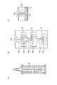
- FIG. 1 (a) and 1 (b) are specific examples of the appearance of a collecting board according to an embodiment of the present invention.
- FIG. 1 (a) is a front view
- FIG. 1 (b) is a plan view.
- 2A is a front view showing the appearance of the classifier
- FIG. 2B is a partially enlarged cross-sectional view showing a longitudinal section of a part of the classifier of FIG. 2A
- FIG. 2C is FIG. It is a fragmentary sectional view showing a part of b).
- FIG. 3 is a schematic diagram showing a list of substances not included in brake abrasion powder.
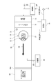
- FIG. 4 is a block diagram showing a configuration example of a system including a wear powder collecting device.
- FIG. 4 is a block diagram showing a configuration example of a system including a wear powder collecting device.
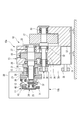
- FIG. 5 is a longitudinal sectional view showing a configuration example of a brake mounting portion of the brake test device.
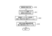
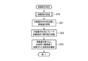
- FIG. 6 is a flowchart showing the manufacturing process of the collecting board.
- FIG. 7 is a flowchart showing a procedure for measuring brake abrasion powder.
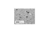
- FIG. 8 is a front view showing an example of an image when the wear powder collected by using the collecting board of the embodiment of the present invention is observed by a scanning electron microscope.
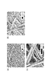
- 9 (a), 9 (b), and 9 (c) are examples of images when abrasion powder collected using a fluororesin-treated glass fiber collecting plate is observed with a scanning electron microscope.
- FIG. 10 (a), 10 (b), and 10 (c) are examples of images when wear powder collected using a collecting plate made of aluminum is observed with a scanning electron microscope.
- FIG. 1A is a front view
- FIG. 1B is a plan view.
- the collecting plate 61 shown in FIGS. 1A and 1B is formed in a thin disk shape.
- This collecting board 61 is composed of a base material 61a and a thin film 61b formed on the surface thereof.
- aluminum is used as the material of the base material 61a.
- the thin film 61b is formed on the surface of the substrate 61a by electroless nickel plating.
- the material and thickness of the base material 61a are determined so that the collecting board 61 can secure sufficient strength.
- As the material of the thin film 61b a material not included in the brake wear powder is selected so that the brake wear powder to be measured can be easily distinguished from the thin film 61b.
- SEM scanning electron microscope
- the thin film 61b formed by electroless nickel plating since nickel is not included in the brake wear powder, when the thin film 61b formed by electroless nickel plating is used, it is easy to distinguish the thin film 61b on the collector 61 from the brake wear powder. become. In addition, when observing brake abrasion powder using a scanning electron microscope, it has been confirmed that, for example, nickel hardly affects the observation of the brake abrasion powder.
- the thickness of the thin film 61b is desirably limited so that the influence of the material of the base material 61a does not appear when observing the brake abrasion powder using a scanning electron microscope, for example, to a thickness of 5 [ ⁇ m] or more. It is preferable to specify.
- the surface of the thin film 61b is mirror-polished to be smooth. That is, the surface roughness of the thin film 61b is defined so as to be at least equal to or less than the particle diameter of the brake wear powder to be observed.
- FIG. 2A shows an example of the appearance of a classifier 62 that can be used to collect wear powder.
- FIG. 2B shows an enlarged vertical cross section of a part of the classifier 62 shown in FIG.
- FIG. 2C shows a part of FIG.
- the classifier 62 shown in FIGS. 2A to 2C is a known device called a low-pressure cascade impactor.
- the classifier 62 can collect and collect the abrasion powder from the air flow by size by introducing an air flow including abrasion powder generated by a brake device of an automobile, for example.
- a special collecting plate 61 shown in FIGS. 1A and 1B is used.
- the classifier 62 shown in FIG. 2A has a structure in which ten collecting stages are vertically stacked and connected in series in the direction of airflow. In the example shown in FIG. 2B, three collecting stages are continuously arranged vertically. As shown in FIG. 2B, each collection stage of the classifier 62 has a flow path of an air flow 62c including a nozzle 62a, and a collection unit 62b. Each collection part 62b is arranged in a plate shape at a position facing the opening of the nozzle 62a. A collecting board 61 is arranged in the collecting section 62b of each collecting stage.
- the diameters of the nozzles 62a of the plurality of collecting stages of the classifier 62 are formed so as to gradually decrease from the upper stage toward the lower stage. That is, the upper collecting stage is configured to collect solid particles having a large particle size, and the lower collecting stage is configured to collect solid particles having a small particle size.
- the airflow 62c passes through the nozzle 62a and travels at high speed toward the front collecting plate 61. Then, particles such as the abrasion powder 63 contained in the airflow 62c are collected by the collection plate 61 by inertial collision. The airflow 62c other than the collected particles goes further downstream.
- a general collector used for the classifier 62 is made of aluminum, glass fiber, or the like as a material. In an electron microscope, a sample stage made of carbon is generally used.
- FIG. 3 shows a list of materials that are not included in the brake wear powder and that can be plated. That is, FIG. 3 shows a material that can be plated, other than components that may be included in a friction material used in a general brake device such as an automobile or brake wear powder generated by wear of a rotor.
- capture is performed using any of aluminum, chromium, cobalt, nickel, copper, zinc, ruthenium, rhodium, palladium, silver, cadmium, indium, tin, tungsten, iridium, platinum, and gold shown in FIG. It is assumed that at least the surface of the turntable 61 is formed. Thereby, when observing the abrasion powder 63 collected by the collection board 61 with a scanning electron microscope or the like, it becomes possible to distinguish the collection board 61 and the abrasion powder 63 based on a difference in material.
- the thin film 61b of the collecting plate 61 shown in FIG. 1A can be formed by plating. Accordingly, if the strength required for the collecting plate 61 is sufficiently ensured only by the base material 61a, the degree of freedom in selecting the material of the thin film 61b is increased.
- FIG. 4 shows a configuration example of a system including a wear powder collecting device.
- the system shown in FIG. 4 collects abrasion powder generated due to abrasion of the brake pads in the caliper 12 and the disk-shaped rotor 14 when the brake 11 used in an automobile or the like operates, and the components thereof are collected. , Shape, size, etc. can be analyzed.
- a scanning electron microscope not shown in FIG.
- the brake 11 shown in FIG. 4 is connected to a brake test device 10 described later, and is held in a state where the rotation of the rotor 14 and the operation of the caliper 12 are possible.
- the brake 11 is arranged in the inner space of the brake hood 50 as shown in FIG. In other words, the part where the wear powder is generated and the part where the generated wear powder scatters are covered in a state where the entire periphery thereof is sealed with the brake hood 50.
- a HEPA (High Efficiency Particulate Air Filter) filter 72 is disposed on the right side of the brake hood 50, and a blower 71 is disposed on the right side thereof.
- the blower 71 can blow outside air into the inner space of the brake hood 50.
- the amount of air blown by the blower 71 is variable and is controlled by a control signal SG1.
- the HEPA filter 72 removes dust and the like from the air sent by the blower 71 and cleans the air.
- an air sampler 60 is connected to the tip 50a of the brake hood 50.
- the air sampler 60 can suck the airflow 58 from a portion communicating with the inner space of the brake hood 50 and collect the floating wear powder contained in the airflow 58.
- the air sampler 60 has a suction capacity of, for example, about 500 [liter / minute], but the suction flow rate is variable. When controlling the amount of air blown by the blower 71, the suction flow rate of the air sampler 60 may be fixed.
- a communication portion 55 is provided so as to be able to communicate with the inner space of the brake hood 50.
- the above-described classifier 62 is connected to one end of the communication portion 55.
- the classifier 62 individually collects abrasion powder of each particle size, for example, less than 2.5 [ ⁇ m], 2.5 [ ⁇ m], 10 [ ⁇ m], etc., based on the principle of aerodynamic diameter. Can be collected and analyzed.
- a pressure sensor 73 is installed inside the brake hood 50.
- the installation position of the pressure sensor 73 is, for example, on the upstream side of the brake 11 with respect to the direction of the airflow 58, and if it is above, the characteristics of the pressure sensor 73 fluctuate due to heat generation of the brake 11. It becomes easier to avoid.
- a pressure sensor 74 is installed in a space outside the brake hood 50. Therefore, the pressure sensor 74 can detect the outside air pressure Pout. Further, the pressure sensor 73 can detect the internal pressure Pin in the brake hood 50.
- the differential pressure gauge 75 outputs a differential pressure signal ⁇ P indicating a differential pressure between the internal pressure Pin detected by the pressure sensor 73 and the external pressure Pout detected by the pressure sensor 74.
- the control unit 80 generates the control signal SG1 based on the differential pressure signal ⁇ P output from the differential pressure gauge 75, and controls the blower 71 so that the differential pressure between the internal pressure Pin and the external pressure Pout is eliminated. For example, when the control unit 80 detects a state in which the internal air pressure Pin is lower than the external air pressure Pout based on the differential pressure signal ⁇ P, the control unit SG1 adjusts the control signal SG1 so as to increase the air volume of the blower 71 per unit time.
- the pressure of the inner space of the brake hood 50 is reduced by the suction of the air by the air sampler 60, but the reduced amount is compensated for by the pressure of the air supplied from the blower 71 into the brake hood 50, and the internal pressure is adjusted by adjusting the air flow rate.
- the control can be performed so that the pressure Pin is equal to the external pressure Pout.
- the control unit 80 controls the amount of air blown by the blower 71 so that the differential pressure between the internal air pressure Pin and the external air pressure Pout disappears, but controls the suction flow rate of the air sampler 60. Or both may be controlled.
- the control unit 80 detects a state in which the internal air pressure Pin is lower than the external air pressure Pout by the differential pressure signal ⁇ P
- the control unit 80 controls to reduce the suction flow rate per unit time.
- the control unit 80 controls so as to increase the suction flow rate per unit time.
- FIG. 5 is a longitudinal sectional view showing a configuration example of a brake test device including the wear powder collecting device shown in FIG.
- the basic configuration of the brake test apparatus 10 shown in FIG. 5 is the same as that of a known technique such as Japanese Patent Application Laid-Open No. 10-300977, and further covers the brake 11 in order to collect wear powder.
- a brake hood (cover) 50 and a seal structure for preventing external dust from flowing into the gap are added.
- the brake test apparatus 10 includes a low-speed rotating shaft 15 to which the rotor 14 of the brake 11 is attached, a high-speed rotating shaft 16 arranged in parallel with the low-speed rotating shaft 15, and an inertial body attached to the high-speed rotating shaft 16. And a flywheel 17. Further, the brake test apparatus 10 includes a deceleration unit 18 that reduces the rotation speed of the high-speed rotation shaft 16 and transmits the reduced rotation speed to the low-speed rotation shaft 15, a motor 19 that drives the high-speed rotation shaft 16, a base 13 that supports each unit, A control unit for controlling each unit and a measuring unit (not shown) for measuring various data of the brake 11 are provided.
- the low-speed rotating shaft 15 includes a first rotating shaft 21 and a second rotating shaft 23 connected by a universal joint 22.
- a large-diameter disk portion 24 is provided at the left end of the second rotation shaft 23 in the drawing, and the rotor 14 is fitted to the disk portion 24.
- the low-speed rotating shaft 15 is supported by bearings 25 and 26 attached to the base 13.
- the large gear 27 of the speed reduction means 18 is attached to a portion between the bearings 25 and 26 of the low-speed rotating shaft 15.
- a sleeve 20 fixed to the base 13 is disposed on the left side of the low-speed rotation shaft 15.
- a housing 28 is attached to the sleeve 20 via a bearing.
- the caliper 12 of the brake 11 is mounted on the flange portion 29 of the housing 28 via a plate 30.
- the high-speed rotating shaft 16 is supported by bearings 31, 32, 33 attached to the base 13. Further, a small gear 34 is formed on the left side of the center of the high-speed rotating shaft 16 in the figure.
- the large gear 27 attached to the low-speed rotating shaft 15 is meshed with the small gear 34.
- the large gear 27 and the small gear 34 constitute the speed reduction means 18.
- the above-described flywheel 17 is attached to the high-speed rotation shaft 16, and the flywheel 17 is disposed in a concave portion 35 provided in the base 13.
- a pulley 36 is fitted to the left end of the high-speed rotating shaft 16 in the drawing.
- the above-described motor 19 is arranged in a concave groove 37 provided at the lower end of the base 13, and a pulley 38 is attached to a rotating shaft thereof.
- a belt 39 is wound around a pulley 36 of the high-speed rotating shaft 16 and a pulley 38 of the rotating shaft of the motor 19.
- the high-speed rotating shaft 16 is driven by the motor 19.
- the brake test apparatus 10 shown in FIG. 5 when the high-speed rotating shaft 16 is driven by the motor 19, the rotational force of the high-speed rotating shaft 16 is transmitted to the low-speed rotating shaft 15 via the speed reducing means 18.
- the rotor 14 attached to the low-speed rotation shaft 15 rotates.
- the friction material 40 in the caliper 12 is pressed against the rotor 14.
- the brake characteristic of the brake 11 can be determined by measuring the distortion of the low-speed rotating shaft 15 and other various data.
- the brake hood 50 is fixed outside the non-rotating housing (caliper holding means) 28.
- the brake hood 50 covers the entire outside of the brake mounting portion 10b including the caliper 12 and the rotor 14 of the brake 11, and accommodates them inside.
- the friction material 40 in the caliper 12 When the friction material 40 in the caliper 12 is pressed against the rotor 14, the pressing surfaces of the rotor 14 and the friction material 40 are worn by the frictional force. In addition, the rotor 14 and the friction material 40 generate abrasion powder with the abrasion, and a part of the abrasion powder is suspended in the air. Therefore, it is possible to collect and measure the generated wear powder in the air.
- FIG. 6 shows an outline of a manufacturing process of the collecting plate 61 shown in FIGS. 1 (a) and 1 (b). The manufacturing process of FIG. 6 will be described below.
- a thin plate of aluminum is prepared as a material, and the base material 61a of the collecting board 61 is formed.
- a disk-shaped substrate 61a having a diameter of 25 [mm] and a thickness of 0.55 [mm] and a flat surface is formed (S11).
- the base material 61a is subjected to electroless nickel plating to form a nickel thin film 61b on the surface (S12).
- the thickness of the thin film 61b is 5 [ ⁇ m] or more.
- the surface of the collector 61 on which the thin film 61b is formed is subjected to a surface polishing treatment to remove irregularities and scratches on the surface (S13).
- a surface polishing treatment to remove irregularities and scratches on the surface (S13).
- the surface roughness of the collecting board 61 is reduced to the particle diameter of the wear powder 63 or less.
- the abrasion powder 63 is not buried in the scratches or dents on the surface of the collecting board 61, and further, there is no difference in the position of each abrasion powder 63 (distance from the observation side to each particle).
- FIG. 7 shows a procedure for measuring the brake wear powder.
- the procedure of FIG. 7 will be described below.
- a collecting plate 61 manufactured by the manufacturing process (S10) shown in FIG. 6 is prepared, and is installed at a predetermined position of a classifier 62 (S21). That is, the surface of the thin film 61b is opposed to the opening of the nozzle 62a from which the air current 62c blows out, in the collecting section 62b of the collecting stage capable of collecting the wear powder 63 having the particle size to be observed, that is, FIG. Arrange as in c).
- the brake test apparatus 10 is operated to perform a test of the brake 11 ( S22).
- the airflow containing the abrasion powder 63 generated by the brake 11 is introduced into the inlet of the classifier 62 via the distal end portion 51a of the brake hood 50 and the communication portion 55. Therefore, the abrasion powder 63 is collected by the collecting board 61.
- the collecting plate 61 that has collected the abrasion powder 63 is taken out from the classifier 62 by, for example, an operator's manual operation or by using a predetermined robot, and is collected by a scanning electron microscope (not shown). It is arranged on a sample stage (S23). This makes it possible to observe the wear powder 63 on the collecting board 61 with a scanning electron microscope and to analyze the components of the wear powder 63 and specify the shape and size.
- FIG. 8 shows an example of an image when the wear powder collected using the collection board 61 of the embodiment of the present invention is observed with a scanning electron microscope. That is, the collected abrasion powder 63 and the surface of the collection board 61 that has collected the abrasion powder 63 appear in the image of FIG.
- the image shown in FIG. 8 shows an example in which the wear powder 63 generated from the brake device is observed with a scanning electron microscope.
- wear powder 63 having a particle diameter of about 0.1 to several ⁇ m appears in a state that can be clearly distinguished. Therefore, measurement such as component analysis of the wear powder 63, specification of the shape of each particle, and specification of the particle diameter can be easily performed.
- the thin film 61b present in the background of each wear powder 63 is different from the wear powder 63 in the material constituting the thin film 61b. 61b.
- the thickness of the thin film 61b is sufficiently large, the influence of aluminum constituting the base material 61a on the background does not appear in each image.
- the scratches and irregularities on the surface of the thin film 61b are removed in advance by mirror polishing, the wear powder 63 does not become buried in the concave portion, and the distance from the observation side to each particle is the same. The powder 63 clearly appears in the image.
- FIG. 9A shows an example of an image obtained when a wear powder collected by using a general fluororesin-treated glass fiber collector instead of the collector 61 according to the present embodiment is observed with a scanning electron microscope. ), FIG. 9B, and FIG. 9C.
- FIG. 10A shows an example of an image when abrasion powder collected by using a general aluminum collecting plate instead of the collecting plate 61 according to the present embodiment is observed with a scanning electron microscope. , FIG. 10 (b), and FIG. 10 (c).
- a dust measuring device including a collecting plate arranged at a position where gas containing dust generated by a friction material can collide, and measuring the dust collected by the collecting plate by inertia force of the dust. So, The first substance (thin film 61b) constituting at least the surface of the collecting plate (61) is different from the material constituting the component of the second substance contained in the dust (wear powder 63) to be measured. Dust measuring device.
- the first substance includes any one of nickel, chromium, and cobalt.
- the dust measuring device according to the above [1].
- the collecting board has a base material (61a) and a thin film (61b) formed on a surface portion of the base material,
- the thin film is composed of the first substance;
- the dust measuring device according to the above [1] or [2].
- the thickness of the thin film has a predetermined size or more necessary to reduce the influence of the base material on the dust in the observation by the scanning electron microscope,
- the dust measuring device according to the above [3].
- a dust measurement method for measuring dust generated by a friction material A collecting plate (61) is prepared in which at least the first substance constituting the surface against which the dust to be measured collides is different from the material constituting the component of the second substance contained in the dust (S10).
- the collecting plate is placed at a position where the gas containing the dust to be measured (air flow 62c) can collide with the gas (S21),
- a gas containing dust generated by a friction material that generates a braking force is introduced into the vicinity of the collecting plate (S22),
- the dust is collected by the collection board by the inertial force of the dust (S23), Dust measurement method.
- the first substance includes any one of nickel, chromium, and cobalt.
- a thin film (61b) is formed on the surface of the base material (61a) to constitute the collecting plate,
- the thin film is composed of the first substance, The dust measurement method according to the above [5] or [6].
- the present invention it is possible to provide a dust measuring device and a dust measuring method that facilitate observation of wear powder generated from a brake device.
- the present invention having this effect is useful for a dust measuring device and a dust measuring method for collecting and measuring the dust from a gas containing dust generated by a friction material generating a braking force.
Landscapes
- Chemical & Material Sciences (AREA)
- Life Sciences & Earth Sciences (AREA)
- Health & Medical Sciences (AREA)
- Pathology (AREA)
- General Physics & Mathematics (AREA)
- Physics & Mathematics (AREA)
- Immunology (AREA)
- Analytical Chemistry (AREA)
- Biochemistry (AREA)
- General Health & Medical Sciences (AREA)
- Dispersion Chemistry (AREA)
- Engineering & Computer Science (AREA)
- Molecular Biology (AREA)
- Biomedical Technology (AREA)
- Signal Processing (AREA)
- Sampling And Sample Adjustment (AREA)
- Analysing Materials By The Use Of Radiation (AREA)
Abstract
Dans la présente invention, une première substance composant au moins la surface d'une plaque de capture (61) disposée dans un classificateur est amenée à être différente des matières constitutives d'une seconde substance incluse dans la poudre d'usure de frein à mesurer. Un matériau approprié pour le placage, tel que le nickel, le chrome ou le cobalt, est utilisé en tant que première substance. Un substrat (61a) est utilisé pour assurer une résistance et un film mince (61b) est formé sur la surface du substrat par placage. Le film mince (61b) est conçu de façon à être suffisamment épais pour réduire l'influence de la substance du substrat (61a) pendant l'observation à l'aide d'un microscope électronique à balayage. La surface de la planche de capture est observée après que la rugosité de celle-ci a été polie en miroir et les positions de la poudre d'usure capturée ont été alignées sur celle-ci. La pression de capot d'un dispositif de test de frein est commandée de telle sorte que la poussière et les salissures autres que la poudre d'usure ne sont pas collectées.
Priority Applications (1)
| Application Number | Priority Date | Filing Date | Title |
|---|---|---|---|
| EP19869029.9A EP3862744A4 (fr) | 2018-10-05 | 2019-10-03 | Dispositif de mesure de poussière et procédé de mesure de poussière |
Applications Claiming Priority (2)
| Application Number | Priority Date | Filing Date | Title |
|---|---|---|---|
| JP2018-190111 | 2018-10-05 | ||
| JP2018190111A JP7182125B2 (ja) | 2018-10-05 | 2018-10-05 | 粉塵測定装置および粉塵測定方法 |
Publications (1)
| Publication Number | Publication Date |
|---|---|
| WO2020071510A1 true WO2020071510A1 (fr) | 2020-04-09 |
Family
ID=70055676
Family Applications (1)
| Application Number | Title | Priority Date | Filing Date |
|---|---|---|---|
| PCT/JP2019/039202 Ceased WO2020071510A1 (fr) | 2018-10-05 | 2019-10-03 | Dispositif de mesure de poussière et procédé de mesure de poussière |
Country Status (3)
| Country | Link |
|---|---|
| EP (1) | EP3862744A4 (fr) |
| JP (1) | JP7182125B2 (fr) |
| WO (1) | WO2020071510A1 (fr) |
Cited By (3)
| Publication number | Priority date | Publication date | Assignee | Title |
|---|---|---|---|---|
| CN114311162A (zh) * | 2021-11-24 | 2022-04-12 | 重庆祥格家居有限公司 | 门板切割装置 |
| WO2022130854A1 (fr) * | 2020-12-14 | 2022-06-23 | 株式会社堀場製作所 | Dispositif et procédé de mesure de poussière de frein |
| WO2024262051A1 (fr) * | 2023-06-23 | 2024-12-26 | 公益財団法人鉄道総合技術研究所 | Dispositif de collecte, système de mesure, procédé de collecte et procédé de mesure de matériau particulaire |
Families Citing this family (1)
| Publication number | Priority date | Publication date | Assignee | Title |
|---|---|---|---|---|
| JP2026027925A (ja) * | 2024-08-06 | 2026-02-19 | 株式会社ブリヂストン | 摩耗粉の捕集装置及び摩耗粉の捕集方法 |
Citations (12)
| Publication number | Priority date | Publication date | Assignee | Title |
|---|---|---|---|---|
| JPS61173132A (ja) * | 1984-11-05 | 1986-08-04 | ウイリアム・ウエイ−リ・チヤング | 微量分析用粒子サンプラ装置及びその使用方法 |
| JPS6375639A (ja) | 1986-09-19 | 1988-04-06 | Hitachi Ltd | 粒子捕集装置 |
| JPH0221345U (fr) * | 1988-07-27 | 1990-02-13 | ||
| US5162053A (en) * | 1987-09-24 | 1992-11-10 | Kowalski Jr Walter J | Vehicular brake material collection system |
| JPH10202192A (ja) | 1997-01-21 | 1998-08-04 | Fuji Xerox Co Ltd | 気流分級機及び静電荷像現像用トナーの製造方法 |
| JPH10300597A (ja) | 1997-04-28 | 1998-11-13 | Akebono Brake Ind Co Ltd | ブレーキ試験装置 |
| JPH11311272A (ja) * | 1998-04-30 | 1999-11-09 | Hitachi Chem Co Ltd | ディスクブレーキパッド |
| JP2015025713A (ja) * | 2013-07-25 | 2015-02-05 | 株式会社アドヴィックス | 摩擦部材の摩擦摩耗現象解析装置 |
| WO2015159870A1 (fr) * | 2014-04-18 | 2015-10-22 | 株式会社堀場製作所 | Dispositif de dispersion d'échantillon et procédé de dispersion d'échantillon |
| JP2016100316A (ja) * | 2014-11-26 | 2016-05-30 | 住友金属鉱山株式会社 | 試料台 |
| WO2017033219A1 (fr) * | 2015-08-21 | 2017-03-02 | 株式会社 日立ハイテクノロジーズ | Unité de support d'observation pour microscope à particules chargées et procédé d'observation d'échantillon faisant intervenir ladite unité |
| JP2018190111A (ja) | 2017-04-28 | 2018-11-29 | 横河電機株式会社 | 校正作業支援装置、校正作業支援方法、校正作業支援プログラム及び記録媒体 |
Family Cites Families (4)
| Publication number | Priority date | Publication date | Assignee | Title |
|---|---|---|---|---|
| US4570494A (en) * | 1984-04-11 | 1986-02-18 | The United States Of America As Represented By The United States Department Of Energy | Apparatus for sampling and characterizing aerosols |
| WO2012114458A1 (fr) * | 2011-02-22 | 2012-08-30 | 株式会社日立製作所 | Dispositif et procédé de capture de micro-organismes dans l'atmosphère |
| WO2015138677A1 (fr) * | 2014-03-14 | 2015-09-17 | Particle Measuring Systems, Inc. | Impacteur de particules avec ajustement de hauteur sélectif |
| WO2017097901A1 (fr) * | 2015-12-09 | 2017-06-15 | Horiba Europe Gmbh | Dispositif pour détecter et mesurer la poussière de frein |
-
2018
- 2018-10-05 JP JP2018190111A patent/JP7182125B2/ja active Active
-
2019
- 2019-10-03 WO PCT/JP2019/039202 patent/WO2020071510A1/fr not_active Ceased
- 2019-10-03 EP EP19869029.9A patent/EP3862744A4/fr active Pending
Patent Citations (12)
| Publication number | Priority date | Publication date | Assignee | Title |
|---|---|---|---|---|
| JPS61173132A (ja) * | 1984-11-05 | 1986-08-04 | ウイリアム・ウエイ−リ・チヤング | 微量分析用粒子サンプラ装置及びその使用方法 |
| JPS6375639A (ja) | 1986-09-19 | 1988-04-06 | Hitachi Ltd | 粒子捕集装置 |
| US5162053A (en) * | 1987-09-24 | 1992-11-10 | Kowalski Jr Walter J | Vehicular brake material collection system |
| JPH0221345U (fr) * | 1988-07-27 | 1990-02-13 | ||
| JPH10202192A (ja) | 1997-01-21 | 1998-08-04 | Fuji Xerox Co Ltd | 気流分級機及び静電荷像現像用トナーの製造方法 |
| JPH10300597A (ja) | 1997-04-28 | 1998-11-13 | Akebono Brake Ind Co Ltd | ブレーキ試験装置 |
| JPH11311272A (ja) * | 1998-04-30 | 1999-11-09 | Hitachi Chem Co Ltd | ディスクブレーキパッド |
| JP2015025713A (ja) * | 2013-07-25 | 2015-02-05 | 株式会社アドヴィックス | 摩擦部材の摩擦摩耗現象解析装置 |
| WO2015159870A1 (fr) * | 2014-04-18 | 2015-10-22 | 株式会社堀場製作所 | Dispositif de dispersion d'échantillon et procédé de dispersion d'échantillon |
| JP2016100316A (ja) * | 2014-11-26 | 2016-05-30 | 住友金属鉱山株式会社 | 試料台 |
| WO2017033219A1 (fr) * | 2015-08-21 | 2017-03-02 | 株式会社 日立ハイテクノロジーズ | Unité de support d'observation pour microscope à particules chargées et procédé d'observation d'échantillon faisant intervenir ladite unité |
| JP2018190111A (ja) | 2017-04-28 | 2018-11-29 | 横河電機株式会社 | 校正作業支援装置、校正作業支援方法、校正作業支援プログラム及び記録媒体 |
Non-Patent Citations (1)
| Title |
|---|
| See also references of EP3862744A4 |
Cited By (5)
| Publication number | Priority date | Publication date | Assignee | Title |
|---|---|---|---|---|
| WO2022130854A1 (fr) * | 2020-12-14 | 2022-06-23 | 株式会社堀場製作所 | Dispositif et procédé de mesure de poussière de frein |
| JPWO2022130854A1 (fr) * | 2020-12-14 | 2022-06-23 | ||
| JP7723685B2 (ja) | 2020-12-14 | 2025-08-14 | 株式会社堀場製作所 | ブレーキダスト測定装置及びブレーキダスト測定方法 |
| CN114311162A (zh) * | 2021-11-24 | 2022-04-12 | 重庆祥格家居有限公司 | 门板切割装置 |
| WO2024262051A1 (fr) * | 2023-06-23 | 2024-12-26 | 公益財団法人鉄道総合技術研究所 | Dispositif de collecte, système de mesure, procédé de collecte et procédé de mesure de matériau particulaire |
Also Published As
| Publication number | Publication date |
|---|---|
| JP2020060386A (ja) | 2020-04-16 |
| EP3862744A4 (fr) | 2022-08-03 |
| EP3862744A1 (fr) | 2021-08-11 |
| JP7182125B2 (ja) | 2022-12-02 |
Similar Documents
| Publication | Publication Date | Title |
|---|---|---|
| WO2020071510A1 (fr) | Dispositif de mesure de poussière et procédé de mesure de poussière | |
| JP6720423B2 (ja) | ブレーキダストを検出及び測定するための装置 | |
| EP3783332B1 (fr) | Dispositif de collecte de poudre abrasive, système d'analyse, procédé de collecte de poudre abrasive et procédé d'analyse | |
| Wahlström et al. | A pin-on-disc simulation of airborne wear particles from disc brakes | |
| Wahlström et al. | Size, shape, and elemental composition of airborne wear particles from disc brake materials | |
| DE102017006349B4 (de) | Vorrichtung zur Messung und Klassifizierung der Partikelemissionen einer Radbremse eines Fahrzeuges | |
| JP3658126B2 (ja) | エアフィルタテスト方法及びそれに使用するテスト装置 | |
| US8012239B2 (en) | Method and apparatus for detecting leaks in bashouse bags | |
| JP4913707B2 (ja) | フィルタの検査方法及びフィルタ検査装置 | |
| Wahlström et al. | Airborne wear particles from passenger car disc brakes: a comparison of measurements from field tests, a disc brake assembly test stand, and a pin-on-disc machine | |
| EP0943088A1 (fr) | Systeme de controle de tranches distinguant les puits et les particules | |
| CN102175579B (zh) | 一种利用振动特征的润滑油颗粒污染度监测装置 | |
| Wahlström et al. | A disc brake test stand for measurement of airborne wear particles | |
| CN101027553A (zh) | 在辊式磨中用于表示磨碎料特征的系统和方法 | |
| CN118687916B (zh) | 一种基于整车的制动磨损颗粒物采集装置 | |
| KR20110043621A (ko) | 불투명 유체 중의 입자를 인―라인 모니터링하기 위한 시스템과 방법 그리고 다성분 유체에서 선택적 물체 조작과정 | |
| JP2001289769A (ja) | 集塵/カウント装置 | |
| JP3358560B2 (ja) | 粉粒体中の異物検査方法および異物検査装置 | |
| JPH10318908A (ja) | 花粉モニター | |
| Abdel-Salam | Aerosol sampling methods in workplace and ambient environments | |
| CN115235773A (zh) | 一种滑油在线屑末监测器验证设备 | |
| JPH0521561A (ja) | 鏡面ウエハの異物検出方法及び装置並びにその分析方法及び装置 | |
| JPH07171325A (ja) | フィルター装置 | |
| JP3552389B2 (ja) | 浮遊粉塵測定装置 | |
| CN118179920B (zh) | 一种金属合金粉末制备用筛分设备 |
Legal Events
| Date | Code | Title | Description |
|---|---|---|---|
| 121 | Ep: the epo has been informed by wipo that ep was designated in this application |
Ref document number: 19869029 Country of ref document: EP Kind code of ref document: A1 |
|
| NENP | Non-entry into the national phase |
Ref country code: DE |
|
| WWE | Wipo information: entry into national phase |
Ref document number: 2019869029 Country of ref document: EP |
|
| ENP | Entry into the national phase |
Ref document number: 2019869029 Country of ref document: EP Effective date: 20210506 |