WO2020075484A1 - メタルガスケット - Google Patents
メタルガスケット Download PDFInfo
- Publication number
- WO2020075484A1 WO2020075484A1 PCT/JP2019/037159 JP2019037159W WO2020075484A1 WO 2020075484 A1 WO2020075484 A1 WO 2020075484A1 JP 2019037159 W JP2019037159 W JP 2019037159W WO 2020075484 A1 WO2020075484 A1 WO 2020075484A1
- Authority
- WO
- WIPO (PCT)
- Prior art keywords
- gasket
- metal
- metal gasket
- sealing property
- circumferential groove
- Prior art date
- Legal status (The legal status is an assumption and is not a legal conclusion. Google has not performed a legal analysis and makes no representation as to the accuracy of the status listed.)
- Ceased
Links
Images


Classifications
-
- F—MECHANICAL ENGINEERING; LIGHTING; HEATING; WEAPONS; BLASTING
- F16—ENGINEERING ELEMENTS AND UNITS; GENERAL MEASURES FOR PRODUCING AND MAINTAINING EFFECTIVE FUNCTIONING OF MACHINES OR INSTALLATIONS; THERMAL INSULATION IN GENERAL
- F16J—PISTONS; CYLINDERS; SEALINGS
- F16J15/00—Sealings
- F16J15/02—Sealings between relatively-stationary surfaces
- F16J15/06—Sealings between relatively-stationary surfaces with solid packing compressed between sealing surfaces
- F16J15/08—Sealings between relatively-stationary surfaces with solid packing compressed between sealing surfaces with exclusively metal packing
- F16J15/0887—Sealings between relatively-stationary surfaces with solid packing compressed between sealing surfaces with exclusively metal packing the sealing effect being obtained by elastic deformation of the packing
-
- F—MECHANICAL ENGINEERING; LIGHTING; HEATING; WEAPONS; BLASTING
- F16—ENGINEERING ELEMENTS AND UNITS; GENERAL MEASURES FOR PRODUCING AND MAINTAINING EFFECTIVE FUNCTIONING OF MACHINES OR INSTALLATIONS; THERMAL INSULATION IN GENERAL
- F16J—PISTONS; CYLINDERS; SEALINGS
- F16J15/00—Sealings
- F16J15/02—Sealings between relatively-stationary surfaces
- F16J15/06—Sealings between relatively-stationary surfaces with solid packing compressed between sealing surfaces
- F16J15/10—Sealings between relatively-stationary surfaces with solid packing compressed between sealing surfaces with non-metallic packing
- F16J15/12—Sealings between relatively-stationary surfaces with solid packing compressed between sealing surfaces with non-metallic packing with metal reinforcement or covering
- F16J15/128—Sealings between relatively-stationary surfaces with solid packing compressed between sealing surfaces with non-metallic packing with metal reinforcement or covering with metal covering
-
- F—MECHANICAL ENGINEERING; LIGHTING; HEATING; WEAPONS; BLASTING
- F16—ENGINEERING ELEMENTS AND UNITS; GENERAL MEASURES FOR PRODUCING AND MAINTAINING EFFECTIVE FUNCTIONING OF MACHINES OR INSTALLATIONS; THERMAL INSULATION IN GENERAL
- F16J—PISTONS; CYLINDERS; SEALINGS
- F16J15/00—Sealings
- F16J15/02—Sealings between relatively-stationary surfaces
- F16J15/021—Sealings between relatively-stationary surfaces with elastic packing
-
- F—MECHANICAL ENGINEERING; LIGHTING; HEATING; WEAPONS; BLASTING
- F16—ENGINEERING ELEMENTS AND UNITS; GENERAL MEASURES FOR PRODUCING AND MAINTAINING EFFECTIVE FUNCTIONING OF MACHINES OR INSTALLATIONS; THERMAL INSULATION IN GENERAL
- F16J—PISTONS; CYLINDERS; SEALINGS
- F16J15/00—Sealings
- F16J15/02—Sealings between relatively-stationary surfaces
- F16J15/06—Sealings between relatively-stationary surfaces with solid packing compressed between sealing surfaces
- F16J15/08—Sealings between relatively-stationary surfaces with solid packing compressed between sealing surfaces with exclusively metal packing
- F16J15/0806—Sealings between relatively-stationary surfaces with solid packing compressed between sealing surfaces with exclusively metal packing characterised by material or surface treatment
-
- F—MECHANICAL ENGINEERING; LIGHTING; HEATING; WEAPONS; BLASTING
- F16—ENGINEERING ELEMENTS AND UNITS; GENERAL MEASURES FOR PRODUCING AND MAINTAINING EFFECTIVE FUNCTIONING OF MACHINES OR INSTALLATIONS; THERMAL INSULATION IN GENERAL
- F16L—PIPES; JOINTS OR FITTINGS FOR PIPES; SUPPORTS FOR PIPES, CABLES OR PROTECTIVE TUBING; MEANS FOR THERMAL INSULATION IN GENERAL
- F16L23/00—Flanged joints
- F16L23/16—Flanged joints characterised by the sealing means
- F16L23/18—Flanged joints characterised by the sealing means the sealing means being rings
-
- G—PHYSICS
- G21—NUCLEAR PHYSICS; NUCLEAR ENGINEERING
- G21C—NUCLEAR REACTORS
- G21C13/00—Pressure vessels; Containment vessels; Containment in general
- G21C13/02—Details
- G21C13/028—Seals, e.g. for pressure vessels or containment vessels
-
- G—PHYSICS
- G21—NUCLEAR PHYSICS; NUCLEAR ENGINEERING
- G21D—NUCLEAR POWER PLANT
- G21D1/00—Details of nuclear power plant
- G21D1/02—Arrangements of auxiliary equipment
-
- F—MECHANICAL ENGINEERING; LIGHTING; HEATING; WEAPONS; BLASTING
- F16—ENGINEERING ELEMENTS AND UNITS; GENERAL MEASURES FOR PRODUCING AND MAINTAINING EFFECTIVE FUNCTIONING OF MACHINES OR INSTALLATIONS; THERMAL INSULATION IN GENERAL
- F16J—PISTONS; CYLINDERS; SEALINGS
- F16J15/00—Sealings
- F16J15/02—Sealings between relatively-stationary surfaces
- F16J15/06—Sealings between relatively-stationary surfaces with solid packing compressed between sealing surfaces
- F16J15/08—Sealings between relatively-stationary surfaces with solid packing compressed between sealing surfaces with exclusively metal packing
- F16J15/0887—Sealings between relatively-stationary surfaces with solid packing compressed between sealing surfaces with exclusively metal packing the sealing effect being obtained by elastic deformation of the packing
- F16J15/0893—Sealings between relatively-stationary surfaces with solid packing compressed between sealing surfaces with exclusively metal packing the sealing effect being obtained by elastic deformation of the packing the packing having a hollow profile
-
- Y—GENERAL TAGGING OF NEW TECHNOLOGICAL DEVELOPMENTS; GENERAL TAGGING OF CROSS-SECTIONAL TECHNOLOGIES SPANNING OVER SEVERAL SECTIONS OF THE IPC; TECHNICAL SUBJECTS COVERED BY FORMER USPC CROSS-REFERENCE ART COLLECTIONS [XRACs] AND DIGESTS
- Y02—TECHNOLOGIES OR APPLICATIONS FOR MITIGATION OR ADAPTATION AGAINST CLIMATE CHANGE
- Y02E—REDUCTION OF GREENHOUSE GAS [GHG] EMISSIONS, RELATED TO ENERGY GENERATION, TRANSMISSION OR DISTRIBUTION
- Y02E30/00—Energy generation of nuclear origin
-
- Y—GENERAL TAGGING OF NEW TECHNOLOGICAL DEVELOPMENTS; GENERAL TAGGING OF CROSS-SECTIONAL TECHNOLOGIES SPANNING OVER SEVERAL SECTIONS OF THE IPC; TECHNICAL SUBJECTS COVERED BY FORMER USPC CROSS-REFERENCE ART COLLECTIONS [XRACs] AND DIGESTS
- Y02—TECHNOLOGIES OR APPLICATIONS FOR MITIGATION OR ADAPTATION AGAINST CLIMATE CHANGE
- Y02E—REDUCTION OF GREENHOUSE GAS [GHG] EMISSIONS, RELATED TO ENERGY GENERATION, TRANSMISSION OR DISTRIBUTION
- Y02E30/00—Energy generation of nuclear origin
- Y02E30/30—Nuclear fission reactors
Definitions
- the present invention relates to a metal gasket. More specifically, the present invention is used, for example, in connecting pipes in a thermal power plant, a nuclear power plant, a steam engine of a steam turbine ship, a petroleum refining line, a process line of the petrochemical industry, a semiconductor manufacturing line, or the like. Regarding metal gaskets.
- Metal hollow O-rings, metal C-rings, etc. have been proposed as metal gaskets with excellent heat resistance (see, for example, Patent Documents 1 and 2).
- these metal gaskets have a drawback that a large tightening force is required to seal between the flanges. Therefore, it is conceivable to form a protrusion on the sealing surface of the metal gasket in order to reduce the tightening force of the metal gasket, but when the metal gasket having the protrusion is mounted between the flanges and the flanges are tightened, Not only may the projection be crushed and the sealing performance deteriorate, but it is difficult to ensure high sealing performance because it is difficult to manufacture the projection accurately, and stress concentrates on the projection. Therefore, some flanges may be scratched.
- a metal gasket having a groove on the outer diameter side surface or the inner diameter side surface of the metal gasket has been proposed as a metal gasket that has a small tightening force and a good sealing property without providing a protrusion on the sealing surface of the metal gasket.
- Patent Document 3 See, for example, Patent Document 3.
- the metal gasket is mounted between the flanges and has a small tightening force when the flanges are tightened and is excellent in sealing property, there is a possibility that the sealing property is deteriorated when heat history is received.
- JP-A-9-177976 Japanese Patent Laid-Open No. 11-30333 JP-A-2003-156147
- the present invention has been made in view of the above-mentioned conventional art, and it is possible to secure the sealing property by tightening between the flanges with a small tightening force, and to secure the sealing property even when a thermal history is received.
- An object is to provide a metal gasket that can be used.
- the present invention (1) A metal gasket having an elastic body and a metal gasket body having a concave circumferential groove on an outer peripheral surface, wherein the elastic body is inserted into the circumferential groove of the gasket body, and the metal gasket has a longitudinal cross section.
- the upper surface of the gasket body that contacts the material to be sealed is formed with an arc-shaped upper sealing surface that bulges upward
- the lower surface of the gasket body that contacts the material to be sealed has an arc shape that bulges downward.
- a lower sealing surface is formed, the upper sealing surface is provided with an upper flat surface or an upper cutout portion, and the lower sealing surface is provided with a lower flat surface or a lower cutout portion, (2)
- the metal gasket according to (1) wherein the gasket body has a surface hardness of 15 to 250 HV, and (3) the gasket body is made of aluminum, aluminum alloy, stainless steel, Inconel, carbon steel, lead, gold, silver,
- a metal gasket that can secure the sealing property by tightening between the flanges with a small tightening force and can secure the sealing property even when a thermal history is received.
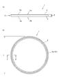
- (A) is a schematic side view showing one embodiment of the metal gasket of the present invention
- (b) is a schematic plan view showing one embodiment of the metal gasket.
- the metal gasket of the present invention is, as described above, a metal gasket body having a concave circumferential groove on the outer peripheral surface and a metal gasket having an elastic body.
- an elastic body is inserted in a circumferential groove of the gasket body, and in a vertical cross section of the metal gasket, an arc-like shape having an upward bulge on an upper surface of the gasket body that comes into contact with a material to be sealed.
- An upper sealing surface is formed, and an arc-shaped lower sealing surface having a bulge toward the lower side is formed on the lower surface of the gasket body that contacts the material to be sealed, and the upper sealing surface is provided with an upper flat surface or an upper cutout portion.
- the lower sealing surface is provided with a lower flat surface or a lower cutout portion.
- the metal gasket of the present invention has the above-mentioned structure, it is possible to secure the sealing property by tightening the flanges with a small tightening force, and it is possible to secure the sealing property even when heat history is received. The excellent effect of being able to be exhibited.
- FIG. 1A is a schematic side view showing one embodiment of the metal gasket of the present invention
- FIG. 1B is a schematic plan view showing one embodiment of the metal gasket
- FIG. 2 is a schematic cross-sectional view showing one embodiment of the metal gasket 1 in the XX section shown in FIG. 1 (b).
- the metal gasket 1 of the present invention has a metal gasket main body 2 and an elastic body 4 each having a concave circumferential groove 3 on its outer peripheral surface.
- An elastic body 4 is inserted in the circumferential groove 3 of the gasket body 2.
- an arc-shaped upper sealing surface 2a having an upward bulge is formed on the upper surface of the gasket body 2 that contacts the material to be sealed, and the upper surface of the gasket body 2 that contacts the material to be sealed is formed on the lower surface of the gasket body 2.
- An arc-shaped lower sealing surface 2b having a bulge toward the lower portion is formed.
- the upper seal surface 2a and the lower seal surface 2b are provided with an upper cutout portion 5a and a lower cutout portion 5b, respectively.
- the surface hardness (Vickers hardness) of the gasket body 2 is preferably 15 HV or more, and more preferably 19 HV or more, from the viewpoint of securing the sealing property by tightening between the flanges with a small tightening force. Further, the surface hardness (Vickers hardness) of the gasket body 2 is preferably 250 HV or less, more preferably 220 HV or less, further preferably 175 HV or less, from the viewpoint of securing the sealing property by tightening between the flanges with a small tightening force. It is more preferably 170 HV or less.
- the material of the gasket body 2 is aluminum, aluminum alloy, stainless steel, inconel, carbon steel, lead, gold, silver, copper, nickel, tantalum, from the viewpoint of securing the sealability by tightening between the flanges with a small tightening force.
- Chrome molybdenum steel, monel preferably a metal selected from the group consisting of titanium and magnesium alloys, more preferably aluminum, an aluminum alloy, stainless steel and a metal selected from the group consisting of Inconel, aluminum or More preferably stainless steel.
- Examples of the aluminum alloy include an aluminum-iron alloy, an aluminum-copper alloy, an aluminum-manganese alloy, an aluminum-magnesium alloy, an aluminum-zinc alloy, and an aluminum-nickel alloy, but the present invention is limited to such examples. It is not limited.
- stainless steel examples include SUS304, SUS316, SUS430, SUS630, SUS631, SUS633, and SUS420J2, but the present invention is not limited to these examples.
- examples of the metal other than magnesium used in the magnesium alloy include lithium, calcium, aluminum, zinc, titanium, manganese, zirconium, yttrium, tantalum, neodymium, niobium, and the like, but the present invention is such an example. It is not limited to only.
- the planar shape of the metal gasket 1 may be an annular shape as shown in FIG. 1 (b), or may be a polygonal shape such as a quadrangle shape, but is usually an annular shape.
- the outer diameter L of the metal gasket 1 cannot be unconditionally determined because it depends on the use of the metal gasket 1. Therefore, it is preferable to appropriately determine the outer diameter L according to the use of the metal gasket 1, but usually about 2 mm to 3 m. Is.
- the cross-sectional shape of the gasket body 2 in the XX portion shown in FIG. 1 (b) is a substantially circular shape as shown in FIG. 2, but the present invention is not limited only to the cross-sectional shape.
- the shape may be polygonal.
- the cross-sectional shape of the gasket body 2 is preferably circular.
- the circular shape is a concept including not only a perfect circle but also a vertically long elliptical shape, a horizontally long elliptical shape, and a track elliptical shape.
- the arc-shaped upper sealing surface 2a having a bulge toward the upper side is formed on the upper surface of the gasket body 2, and the bulge toward the lower side is formed on the lower surface of the gasket body 2.
- An arc-shaped lower sealing surface 2b is formed.
- the arcuate shape is not limited to a true circular arc, and is similar to the cross-sectional shape of the gasket body 2, and is a concept including a vertically elongated elliptical arc, a horizontally elongated elliptical arc, and a track elliptical arc.
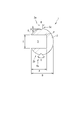
- FIG. 3 is a schematic cross-sectional view showing one embodiment of the gasket body 2 in the XX section shown in FIG. 1 (b).
- the upper notch 5a is provided on the upper sealing surface 2a of the gasket body 2
- the lower notch 5b is provided on the lower sealing surface 2b of the gasket body 2.
- the depth D of the upper notch portion 5a and the lower notch portion 5b differs depending on the material of the gasket main body 2, the size of the gasket main body 2 and the like and therefore cannot be determined unconditionally.
- each is preferably 0.1 to 3 mm, and more preferably It is 0.3 to 2 mm, more preferably 0.5 to 1 mm.
- the depth D of the upper notch 5a and the lower notch 5b is determined by drawing a tangent line to the end of the upper notch 5a and the lower notch 5b as shown in FIG. A parallel line is drawn so that a straight line tangent to the bottom of 5a and the lower cutout portion 5b is parallel to the tangent line, which means the distance between the tangent line and the parallel line.
- the width W of the upper notch portion 5a and the lower notch portion 5b differs depending on the material of the gasket body 2, the size of the gasket body 2, and the like, and therefore cannot be determined unconditionally, but tightens between the flanges with a small tightening force. Therefore, from the viewpoint of obtaining the metal gasket 1 which can secure the sealing property and can secure the sealing property even when subjected to a heat history, each is preferably 0.1 to 3 mm, more preferably 0 mm. 0.3 to 2 mm, more preferably 0.5 to 1 mm.
- the width W of the upper cutout 5a and the lower cutout 5b is tangential to the ends of the upper cutout 5a and the lower cutout 5b as shown in FIG. Also, two straight lines perpendicular to the tangent line are drawn starting from the ends of the lower cutouts 5b, respectively, and the distance between the two perpendicular lines is meant.
- the upper notch portion 5a and the lower notch portion 5b can secure the sealing property by tightening between the flanges with a small tightening force, and can secure the sealing property even when heat history is received.
- each is preferably a V-shaped notch.
- the angle ⁇ formed by the groove portion of the V-shaped cutout portion can secure the sealing property by tightening between the flanges with a small tightening force, and the sealing property is ensured even when a thermal history is received.
- a metal gasket 1 that can be manufactured, it is preferably 20 ° or more, more preferably 40 ° or more, still more preferably 45 ° or more, and it is possible to secure the sealing property by tightening between the flanges with a small tightening force. From the viewpoint of obtaining a metal gasket 1 that can be formed and can ensure the sealing property even when subjected to heat history, it is preferably less than 180 °, more preferably 160 ° or less, still more preferably 140 ° or less, and even more. It is preferably 120 ° or less.
- the bottom portion of the V-shaped notch portion may have an acute angle, a flat surface, or an arc shape as shown in FIG. It may be. It is preferable that the bottom of the V-shaped notch has an obtuse angle from the viewpoint of securing the sealing property by tightening between the flanges with a small tightening force.
- the positions of the deepest portions of the upper notch portion 5a and the lower notch portion 5b in the horizontal direction of the metal gasket 1 can secure the sealing property by tightening between the flanges with a small tightening force, and the heat history has been received. From the viewpoint of obtaining the metal gasket 1 capable of ensuring the sealing property even in the case, as shown in FIG. 3, from the deepest end P of the inner side wall of the circumferential groove 3 to the entrance Q of the circumferential groove 3. It is preferable that it exists during the period.
- the upper notch portion 5a and the lower notch portion 5b are not limited to the upper seal surface 2a and the lower seal surface 2b, respectively, and, if necessary, the upper portion inside the circumferential groove 3 for inserting the elastic body 4 described later. They may be provided on the wall surface (not shown) and the lower wall surface (not shown), respectively.
- a circumferential groove 3 for inserting the elastic body 4 is formed inside the gasket body 2.
- both the upper wall surface (not shown) and the lower wall surface (not shown) inside the circumferential groove 3 are formed so as to be flat with the gasket body 2.
- it is not necessarily formed to be a flat surface horizontal to the gasket main body 2, and may be a flat surface having an inclination (taper) with respect to the horizontal direction of the gasket main body 2.
- each is preferably 1 mm or more, and more preferably 1 mm or more. It is at least 0.5 mm, more preferably at least 2 mm.
- the maximum thickness of the gasket body 2 at the innermost end P of the circumferential groove 3 cannot be unconditionally determined because it varies depending on the application of the metal gasket 1 of the present invention, but a small tightening force can be used to reduce the distance between the flanges.
- a small tightening force can be used to reduce the distance between the flanges. From the viewpoint of obtaining the metal gasket 1 which can secure the sealing property by tightening and can secure the sealing property even when subjected to a heat history, preferably 15 mm or less, more preferably 10 mm or less, It is preferably 5 mm or less.
- the inner surface (not shown) of the circumferential groove 3 of the gasket body 2 shown in FIG. 3 is formed by a flat surface, but it does not necessarily have to be formed by a flat surface. It may be formed by a curved surface such as a curved surface or an uneven curved surface.
- the width S of the opening of the circumferential groove 3 differs depending on the application of the metal gasket 1 of the present invention and cannot be unconditionally determined. However, it is necessary to secure the sealing property by tightening the flanges with a small tightening force. Therefore, from the viewpoint of obtaining the metal gasket 1 capable of ensuring the sealing property even when subjected to heat history, the thickness T of the gasket body 2 of the metal gasket 1 shown in FIG. It is preferably about 85%.
- the thickness T of the gasket body 2 cannot be unconditionally determined because it depends on the application of the metal gasket 1, it is preferable to appropriately determine the thickness T according to the application of the metal gasket 1. It is about 15 mm.
- the horizontal length B of the gasket body 2 is different depending on the application of the metal gasket 1 and cannot be unconditionally determined. Therefore, it may be appropriately determined according to the application of the metal gasket 1. It is preferably, but usually about 1 to 15 mm.
- the value of the ratio of the depth A of the circumferential groove 3 of the gasket body 2 to the horizontal length B of the gasket body 2 is small. From the viewpoint of securing the sealing property by tightening between the flanges, preferably 0.1 or more, more preferably 0.2 or more, even more preferably 0.3 or more, still more preferably 0.4 or more, and even more preferably 0.5 or more, preferably 0.95 or less, more preferably 0.9 or less, from the viewpoint of increasing the mechanical strength of the gasket body 2 and securing the sealability by tightening between the flanges with a small tightening force. It is even more preferably 0.88 or less, still more preferably 0.86 or less.
- an elastic body 4 is arranged in the circumferential groove 3 of the gasket body 2.
- the material forming the elastic body 4 include rubber such as fluororubber, silicone rubber, butadiene rubber, styrene-butadiene rubber, acrylonitrile-butadiene rubber, styrene-butadiene rubber, chloroprene rubber and natural rubber, and olefin thermoplastic elastomer.
- Thermoplastic elastomers such as ester-based thermoplastic elastomers, styrene-based thermoplastic elastomers, vinyl chloride-based thermoplastic elastomers, and highly flexible thermoplastic resins such as polytetrafluoroethylene and other fluororesins.
- the present invention is not limited to such examples.
- the heat resistance is excellent, and the sealing property can be secured by tightening between the flanges with a small tightening force, and even if a thermal history is received.
- fluororubber and silicone rubber are preferable, and fluororubber is more preferable.
- a coil spring can be used as the elastic body 4.
- the elastic body 4 has a shape corresponding to the inner shape of the circumferential groove 3 of the gasket body 2.
- the elastic body 4 shown in FIG. 2 is arranged in the circumferential groove 3 so as to come into contact with the inner wall of the circumferential groove 3 of the gasket body 2.
- the surface of the elastic body 4 has an uneven shape.
- a gap may be provided between the elastic body 4 and the inner surface of the circumferential groove 3 by forming a groove or by making the elastic body 4 have a circular or triangular cross-sectional shape.
- the elastic body 4 may be provided with a meat steal 6 as shown in FIG. 4, if necessary.
- 4 is a schematic cross-sectional view showing another embodiment of the metal gasket 1 in the XX section shown in FIG. 1 (b).
- the elastic body 4 may be disposed so as to fill the entire inside of the circumferential groove 3 of the gasket body 2, and as shown in FIG. 2, the inlet portion Q of the circumferential groove 3 of the gasket body 2 may be filled. It may be arranged in the circumferential groove 3 so that the collar portion 2c is formed.
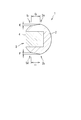
- FIG. 5 is a schematic sectional view showing another embodiment of the metal gasket in the XX section shown in FIG. 1 (b).
- the upper seal surface 2a is provided with the upper cutout portion 5a and the lower seal surface 2b is provided with the lower cutout portion 5b
- the upper flat surface 5c is provided on the upper seal surface 2a
- the lower flat surface 2d is provided on the lower seal surface 2b.
- the upper notch 5a is provided on the upper seal surface 2a and the lower notch 5b is provided on the lower seal surface 2b from the viewpoint of securing the sealing property by tightening the flanges with a small tightening force. Is preferably provided.
- the upper plane 5c and the lower plane 5d may be provided so as to be parallel to the upper sealing surface 2a and the lower sealing surface 2b, respectively, and as shown in FIG. 5, the upper sealing surface 2a and the lower sealing surface 2a, respectively. It may be inclined with respect to the surface 2b.
- the upper flat surface 5c and the lower flat surface 5d are inclined with respect to the upper sealing surface 2a and the lower sealing surface 2b, respectively, from the viewpoint of securing the sealability by tightening between the flanges with a small tightening force. Is preferably provided.
- the length E from the upper end to the lower end in the vertical direction of the upper plane 5c and the length F from the upper end to the lower end in the vertical direction of the lower plane 5d ensure the sealing property by tightening between the flanges with a small tightening force.
- the thickness is preferably 0.1 to 3 mm, more preferably 0.3 to 2 mm, and further preferably 0.5 to 1 mm.
- the length G from the upper end to the lower end in the horizontal direction of the upper flat surface 5c and the length H from the upper end to the lower end in the horizontal direction of the lower flat surface 5d secure the sealing property by tightening between the flanges with a small tightening force.
- each is preferably 0.1 to 3 mm, more preferably 0.3 to 2 mm, and further preferably 0.5 to 1 mm.
- the metal gasket 1 of the present invention configured as described above can secure the sealing property by clamping between the flanges with a small clamping force, and the sealing property is secured even when the heat history is received. be able to. Therefore, the metal gasket 1 of the present invention is used, for example, when connecting pipes in a thermal power plant, a nuclear power plant, a steam engine of a steam turbine ship, a petroleum refining line, a petrochemical industry process line, a semiconductor manufacturing line, or the like. It can be used preferably.
- Example 1 As the gasket body, an aluminum gasket body (surface hardness: 22 HV) having the shape shown in FIGS. 1 to 3 was used.
- the outer diameter L of the gasket body 2 in plan view is 75 mm and the thickness T is 3.5 mm.
- the width S of the opening of the circumferential groove 3 is 2.5 mm
- the minimum thickness of the gasket body 2 at the innermost end P of the inner side wall of the circumferential groove 3 is 0.3 mm
- the circumferential groove 3 has a depth A of 3 mm, a horizontal length B of 3.5 mm, and a depth A and a horizontal length.
- the value of the ratio to the height B (depth A of the circumferential groove 3 / horizontal length B) is 0.86, and the width W of each of the upper cutout 5a and the lower cutout 5b is 4 mm.
- the depth D of the upper notch 5a and the lower notch 5b are respectively A mm, the angle of the upper cutout portion 5a and a V-shaped lower notch 5b notched portion of the groove 3 theta was used gasket main body 2 is 110 °, respectively.
- the metal gasket 1 was produced by mounting the fluororubber elastic body 4 having the shape shown in FIG. 2 in the circumferential groove 3 of the gasket body 2.
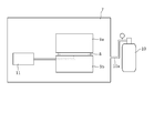
- FIG. 6 is a schematic explanatory diagram of the gasket evaluation test device 7.
- the compressive load when the compressibility obtained based on the above-mentioned reached 17% was measured, and the necessary tightening force was evaluated according to the following evaluation criteria with the compressive load as the necessary tightening force.
- the compressive load when the compressibility reaches 17% means the compressive load (required tightening force) required to eliminate the gap between the gasket 8 and the test platens 9a and 9b.
- the gasket 8 is mounted between the test platen 9a and the test platen 9b in the sealability evaluation test device 7, and a compressive load of 25 kN / m is applied to the gasket 8, and then the helium gas cylinder 10 is supplied with the nozzle 10a from the nozzle 10a. Was injected to fill the evaluation test device 7 with atmospheric pressure helium gas.
- the inside of the gasket 8 was depressurized until the degree of vacuum reached 0.1 Pa, and 5 minutes after the degree of vacuum was reached, from the outside of the gasket 8 to the inside of the gasket 8 The leak amount of the helium gas flowing into the space was measured.
- the sealability was evaluated according to the following evaluation criteria.
- the leak amount of helium gas is less than 4 ⁇ 10 ⁇ 11 Pa ⁇ m 3 / s ⁇ m (detection limit value).
- the leak amount of helium gas is 4 ⁇ 10 ⁇ 11 Pa ⁇ m 3 / s ⁇ m or more and less than 1 ⁇ 10 ⁇ 10 Pa ⁇ m 3 / s ⁇ m.
- the leak amount of helium gas is 1 ⁇ 10 ⁇ 10 Pa ⁇ m 3 / s ⁇ m or more and less than 1 ⁇ 10 ⁇ 9 Pa ⁇ m 3 / s ⁇ m.
- X The leak amount of helium gas is 1 ⁇ 10 ⁇ 9 Pa ⁇ m 3 / s ⁇ m or more.
- the sealing property is examined in the same manner as described above, and it is checked whether or not the leak amount of helium gas has increased from the time of measuring the sealing property, based on the following evaluation criteria.
- the sealing property after heat history was evaluated. ⁇ Evaluation criteria ⁇ ⁇ : No increase in the amount of helium gas leaked. X: An increase in the leak amount of helium gas is recognized.
- Example 1 Comparative Example 1 In Example 1, the gasket body without the elastic body was used as the metal gasket.
- Comparative Example 2 As a conventional gasket, an O-ring made of fluororubber [manufactured by VALQUA CO., LTD., Product number: No. 4640] was used, and the required tightening force, sealing property and sealing property after heat history were evaluated in the same manner as in Example 1. . Table 1 shows the results.
- Comparative Example 3 As a conventional metal gasket, a spring-loaded metal C ring [manufactured by VALQUA CO., LTD., Product number: 3645] was used, and in the same manner as in Example 1, the required tightening force, sealability, and sealability after thermal history were evaluated. Table 1 shows the results.
- Comparative Example 4 As a conventional gasket, a metal hollow O-ring made of stainless steel (SUS304) [manufactured by VALQUA CO., LTD., Product number: 3640] was used, and in the same manner as in Example 1, required tightening force, sealing property and sealing property after heat history was evaluated. Table 1 shows the results.
- the metal gasket obtained in Example 1 can eliminate the gap between the metal gasket and the test platen with a required tightening force as low as 35 kN / m.
- a required tightening force as low as 35 kN / m.
- the metal gasket obtained in Example 1 has excellent sealing properties, and there is no change in the sealing properties after being subjected to a thermal history. Therefore, the steam engines of thermal power plants, nuclear power plants, and steam turbine ships It is considered that it can be suitably used when connecting pipes in a petroleum refining line, a petrochemical industry process line, a semiconductor manufacturing line, and the like.
Landscapes
- Engineering & Computer Science (AREA)
- General Engineering & Computer Science (AREA)
- Mechanical Engineering (AREA)
- Physics & Mathematics (AREA)
- Plasma & Fusion (AREA)
- High Energy & Nuclear Physics (AREA)
- Gasket Seals (AREA)
Abstract
Description
(1)外周面に凹部状の円周溝を有する金属製のガスケット本体および弾性体を有するメタルガスケットであって、前記ガスケット本体の円周溝に弾性体が挿入され、前記メタルガスケットの縦断面において、被シール材と接触するガスケット本体の上面に上部に向かって膨らみを有する円弧状の上部シール面が形成され、被シール材と接触するガスケット本体の下面に下部に向かって膨らみを有する円弧状の下部シール面が形成され、前記上部シール面に上部平面または上部切り欠き部が設けられ、前記下部シール面に下部平面または下部切り欠き部が設けられていることを特徴とするメタルガスケット、
(2)ガスケット本体の表面硬度が15~250HVである前記(1)に記載のメタルガスケット、および
(3)ガスケット本体がアルミニウム、アルミニウム合金、ステンレス鋼、インコネル、炭素鋼、鉛、金、銀、銅、ニッケル、タンタル、クロムモリブデン鋼、モネル、チタンおよびマグネシウム合金からなる群より選ばれた金属で形成されてなる前記(1)または(2)に記載のメタルガスケット
に関する。
ガスケット本体として、図1~図3に示される形状を有するアルミニウム製ガスケット本体(表面硬度:22HV)を用いた。
図6に示されるガスケットの評価試験装置7を用いて必要締付け力を評価した。図6は、ガスケットの評価試験装置7の概略説明図である。
[圧縮率]=[(初期のガスケット8の高さ)-(圧縮後のガスケット8の高さ)]÷[初期のガスケット8の高さ]×100
に基づいて求められる圧縮率が17%に到達したときの圧縮荷重を測定し、当該圧縮荷重を必要締付け力として以下の評価基準にしたがって必要締付け力を評価した。なお、圧縮率が17%に到達したときの圧縮荷重は、ガスケット8と試験プラテン9a,9bとの間の間隙を消滅させるために必要な圧縮荷重(必要締付け力)を意味する。
◎:必要締付け力(圧縮荷重)が50kN/m未満である。
〇:必要締付け力(圧縮荷重)が50kN/m以上、80kN/m未満である。
△:必要締付け力(圧縮荷重)が80kN/m以上、100kN/m未満である。
×:必要締付け力(圧縮荷重)が100kN/m以上である。
ガスケットのシール性を評価する際に図6に示されるガスケットの評価試験装置7を用いた。
◎:ヘリウムガスの漏れ量が4×10-11Pa・m3/s・m(検出限界値)未満である。
〇:ヘリウムガスの漏れ量が4×10-11Pa・m3/s・m以上、1×10-10Pa・m3/s・m未満である。
△:ヘリウムガスの漏れ量が1×10⁻¹⁰Pa・m3/s・m以上、1×10-9Pa・m3/s・m未満である。
×:ヘリウムガスの漏れ量が1×10⁻⁹Pa・m3/s・m以上である。
ガスケットを温度が100℃である恒温槽内に24時間入れて加熱することにより、ガスケットに熱履歴を付与した後、当該ガスケットを室温まで放冷し、恒温槽から取り出した。
〔評価基準〕
◎:ヘリウムガスの漏れ量の増加が認められない。
×:ヘリウムガスの漏れ量の増加が認められる。
ガスケットの必要締付け力、シール性および熱履歴後のシール性の評価結果において、◎の評価を100点、〇の評価を80点、△の評価を60点、×の評価を0点とし、ガスケットの必要締付け力、シール性および熱履歴後のシール性の各得点を合計し、その合計点を表1の総合評価の欄に記載した。
実施例1において、弾性体が使用されていないガスケット本体をメタルガスケットとして使用した。
従来のガスケットとして、フッ素ゴム製のOリング〔(株)バルカー製、品番:No.4640〕を用い、実施例1と同様にして必要締付け力、シール性および熱履歴後のシール性を評価した。その結果を表1に示す。
従来のメタルガスケットとして、ばね入りメタルCリング〔(株)バルカー製、品番:3645〕を用い、実施例1と同様にして必要締付け力、シール性および熱履歴後のシール性を評価した。その結果を表1に示す。
従来のガスケットとして、ステンレス鋼(SUS304)製のメタル中空Oリング〔(株)バルカー製、品番:3640〕を用い、実施例1と同様にして必要締付け力、シール性および熱履歴後のシール性を評価した。その結果を表1に示す。

2 ガスケット本体
2a 上部シール面
2b 下部シール面
2c 鍔部
3 円周溝
4 弾性体
5a 上部切り欠き部
5b 下部切り欠き部
5c 上部平面
5d 下部平面
6 肉盗み
7 シール性の評価試験装置
8 ガスケット
9a 試験プラテン
9b 試験プラテン
10 ヘリウムガスボンベ
11aノズル
12 ヘリウムリークディテクター
Claims (3)
- 外周面に凹部状の円周溝を有する金属製のガスケット本体および弾性体を有するメタルガスケットであって、
前記ガスケット本体の円周溝に弾性体が挿入され、
前記メタルガスケットの縦断面において、被シール材と接触するガスケット本体の上面に上部に向かって膨らみを有する円弧状の上部シール面が形成され、
被シール材と接触するガスケット本体の下面に下部に向かって膨らみを有する円弧状の下部シール面が形成され、
前記上部シール面に上部平面または上部切り欠き部が設けられ、前記下部シール面に下部平面または下部切り欠き部が設けられていることを特徴とするメタルガスケット。 - ガスケット本体の表面硬度が15~250HVである請求項1に記載のメタルガスケット。
- ガスケット本体を構成する金属がアルミニウム、アルミニウム合金、ステンレス鋼、インコネル、炭素鋼、鉛、金、銀、銅およびマグネシウム合金からなる群より選ばれた金属である請求項1または2に記載のメタルガスケット。
Priority Applications (5)
| Application Number | Priority Date | Filing Date | Title |
|---|---|---|---|
| CN201980065984.2A CN112805493A (zh) | 2018-10-10 | 2019-09-24 | 金属垫圈 |
| US17/281,304 US20220003317A1 (en) | 2018-10-10 | 2019-09-24 | Metal gasket |
| EP19871761.3A EP3865738A4 (en) | 2018-10-10 | 2019-09-24 | METAL SEAL |
| JP2020550307A JP7245846B2 (ja) | 2018-10-10 | 2019-09-24 | メタルガスケット |
| KR1020217007321A KR102693594B1 (ko) | 2018-10-10 | 2019-09-24 | 메탈 개스킷 |
Applications Claiming Priority (2)
| Application Number | Priority Date | Filing Date | Title |
|---|---|---|---|
| JP2018191437 | 2018-10-10 | ||
| JP2018-191437 | 2018-10-10 |
Publications (1)
| Publication Number | Publication Date |
|---|---|
| WO2020075484A1 true WO2020075484A1 (ja) | 2020-04-16 |
Family
ID=70163937
Family Applications (1)
| Application Number | Title | Priority Date | Filing Date |
|---|---|---|---|
| PCT/JP2019/037159 Ceased WO2020075484A1 (ja) | 2018-10-10 | 2019-09-24 | メタルガスケット |
Country Status (7)
| Country | Link |
|---|---|
| US (1) | US20220003317A1 (ja) |
| EP (1) | EP3865738A4 (ja) |
| JP (1) | JP7245846B2 (ja) |
| KR (1) | KR102693594B1 (ja) |
| CN (1) | CN112805493A (ja) |
| TW (1) | TWI820220B (ja) |
| WO (1) | WO2020075484A1 (ja) |
Cited By (2)
| Publication number | Priority date | Publication date | Assignee | Title |
|---|---|---|---|---|
| WO2022085577A1 (ja) * | 2020-10-20 | 2022-04-28 | 株式会社バルカー | メタルガスケット |
| CN116006795A (zh) * | 2021-10-21 | 2023-04-25 | 西安恩诺维新石油技术有限公司 | 一种油管用做地面集输管线的螺纹连接装置 |
Citations (7)
| Publication number | Priority date | Publication date | Assignee | Title |
|---|---|---|---|---|
| JPH09177976A (ja) | 1995-12-28 | 1997-07-11 | Nippon Valqua Ind Ltd | 金属中空oリング |
| JPH09264427A (ja) * | 1996-03-28 | 1997-10-07 | Nippon Valqua Ind Ltd | メタルガスケット |
| JPH1130333A (ja) | 1997-07-11 | 1999-02-02 | Nippon Valqua Ind Ltd | メタルcリング |
| JPH11131052A (ja) * | 1997-10-31 | 1999-05-18 | Mitsubishi Cable Ind Ltd | シール |
| JP2001182833A (ja) * | 1999-12-24 | 2001-07-06 | Nippon Valqua Ind Ltd | 金属ガスケット及びその製造方法 |
| JP2003156147A (ja) | 2001-11-16 | 2003-05-30 | Nippon Valqua Ind Ltd | メタルガスケット |
| JP2005036938A (ja) * | 2003-07-18 | 2005-02-10 | Ckd Corp | 金属ガスケットの取付構造 |
Family Cites Families (12)
| Publication number | Priority date | Publication date | Assignee | Title |
|---|---|---|---|---|
| US3869132A (en) * | 1973-07-18 | 1975-03-04 | Pressure Science Inc | Fire resistant sealing ring combination |
| US4618154A (en) * | 1985-07-31 | 1986-10-21 | Freudenthal Merton L | Annular lip type sealing ring with pre-loaded lip portions |
| US5076617A (en) * | 1990-08-10 | 1991-12-31 | Bronnert Herve X | Seal for aseptic fitting assembly |
| JP2991651B2 (ja) * | 1995-12-25 | 1999-12-20 | シーケーディ株式会社 | 金属ガスケット |
| JP3346756B2 (ja) * | 1999-02-15 | 2002-11-18 | 三菱電線工業株式会社 | ジャケットシール |
| FR2823826B1 (fr) * | 2001-04-23 | 2003-07-25 | Commissariat Energie Atomique | Joint d'etancheite metallique elastique ferme a parties saillantes desaxees |
| US8524321B2 (en) * | 2007-01-29 | 2013-09-03 | Praxair Technology, Inc. | Reagent dispensing apparatus and delivery method |
| JP5204550B2 (ja) * | 2008-05-20 | 2013-06-05 | 国立大学法人東北大学 | メタルガスケット |
| US8623145B2 (en) * | 2010-03-25 | 2014-01-07 | Parker-Hannifin Corporation | Substrate processing apparatus with composite seal |
| CN104265892A (zh) * | 2014-09-17 | 2015-01-07 | 江苏亿阀集团有限公司 | 一种用于低温阀门的复合密封圈 |
| CN106051156A (zh) * | 2016-07-27 | 2016-10-26 | 苏州好特斯模具有限公司 | 热敏金属自动密封型热嘴 |
| CN207584012U (zh) * | 2017-08-29 | 2018-07-06 | 慈溪市恒立密封材料有限公司 | 弹簧自紧式金属c型环密封件 |
-
2019
- 2019-09-24 EP EP19871761.3A patent/EP3865738A4/en active Pending
- 2019-09-24 US US17/281,304 patent/US20220003317A1/en not_active Abandoned
- 2019-09-24 KR KR1020217007321A patent/KR102693594B1/ko active Active
- 2019-09-24 WO PCT/JP2019/037159 patent/WO2020075484A1/ja not_active Ceased
- 2019-09-24 JP JP2020550307A patent/JP7245846B2/ja active Active
- 2019-09-24 CN CN201980065984.2A patent/CN112805493A/zh active Pending
- 2019-09-25 TW TW108134591A patent/TWI820220B/zh active
Patent Citations (7)
| Publication number | Priority date | Publication date | Assignee | Title |
|---|---|---|---|---|
| JPH09177976A (ja) | 1995-12-28 | 1997-07-11 | Nippon Valqua Ind Ltd | 金属中空oリング |
| JPH09264427A (ja) * | 1996-03-28 | 1997-10-07 | Nippon Valqua Ind Ltd | メタルガスケット |
| JPH1130333A (ja) | 1997-07-11 | 1999-02-02 | Nippon Valqua Ind Ltd | メタルcリング |
| JPH11131052A (ja) * | 1997-10-31 | 1999-05-18 | Mitsubishi Cable Ind Ltd | シール |
| JP2001182833A (ja) * | 1999-12-24 | 2001-07-06 | Nippon Valqua Ind Ltd | 金属ガスケット及びその製造方法 |
| JP2003156147A (ja) | 2001-11-16 | 2003-05-30 | Nippon Valqua Ind Ltd | メタルガスケット |
| JP2005036938A (ja) * | 2003-07-18 | 2005-02-10 | Ckd Corp | 金属ガスケットの取付構造 |
Non-Patent Citations (1)
| Title |
|---|
| See also references of EP3865738A4 |
Cited By (5)
| Publication number | Priority date | Publication date | Assignee | Title |
|---|---|---|---|---|
| WO2022085577A1 (ja) * | 2020-10-20 | 2022-04-28 | 株式会社バルカー | メタルガスケット |
| CN116324234A (zh) * | 2020-10-20 | 2023-06-23 | 株式会社华尔卡 | 金属密封垫 |
| US12385565B2 (en) | 2020-10-20 | 2025-08-12 | Valqua, Ltd. | Metal gasket |
| CN116324234B (zh) * | 2020-10-20 | 2025-11-25 | 株式会社华尔卡 | 金属密封垫 |
| CN116006795A (zh) * | 2021-10-21 | 2023-04-25 | 西安恩诺维新石油技术有限公司 | 一种油管用做地面集输管线的螺纹连接装置 |
Also Published As
| Publication number | Publication date |
|---|---|
| KR20210062631A (ko) | 2021-05-31 |
| JPWO2020075484A1 (ja) | 2021-09-02 |
| JP7245846B2 (ja) | 2023-03-24 |
| CN112805493A (zh) | 2021-05-14 |
| EP3865738A1 (en) | 2021-08-18 |
| TW202028637A (zh) | 2020-08-01 |
| EP3865738A4 (en) | 2022-06-01 |
| US20220003317A1 (en) | 2022-01-06 |
| TWI820220B (zh) | 2023-11-01 |
| KR102693594B1 (ko) | 2024-08-08 |
Similar Documents
| Publication | Publication Date | Title |
|---|---|---|
| CN108474473B (zh) | 气缸盖衬垫及气缸盖衬垫用不锈钢板 | |
| JP2011528093A (ja) | 取り外し可能なフランジ継ぎ手の封止のためのくし型両面被覆ガスケット | |
| TWI441993B (zh) | 高壓密封裝置 | |
| WO2020075484A1 (ja) | メタルガスケット | |
| US5556113A (en) | O-ring envelope gasket | |
| JP7089389B2 (ja) | メタルガスケット | |
| US9562838B2 (en) | Measuring element made of steel with hardened edge zone | |
| KR101252852B1 (ko) | 아우터링 및 진공 장치용 클램프형 이음매 | |
| JP2017040280A (ja) | 金属リングガスケット | |
| JP7328325B2 (ja) | 鋸歯形メタルガスケット | |
| JP7587595B2 (ja) | メタルガスケット | |
| JP5336944B2 (ja) | 渦巻形ガスケット | |
| JP2003156147A (ja) | メタルガスケット | |
| JP2007010101A (ja) | Oリング及び真空装置用クランプ形継手 | |
| JP2003194226A (ja) | ジャケットシール | |
| WO2019026570A1 (ja) | メタルガスケット | |
| US20070287317A1 (en) | Independent Leg Seal | |
| JP2006291984A (ja) | 低温用ガスケット、それを用いる収容容器及びその密封方法 | |
| Baulch et al. | ASME B16. 20 Jacketed Gaskets Performance Testing | |
| KR20050017007A (ko) | 유체 부품 | |
| JP2015010643A (ja) | うず巻形ガスケット |
Legal Events
| Date | Code | Title | Description |
|---|---|---|---|
| 121 | Ep: the epo has been informed by wipo that ep was designated in this application |
Ref document number: 19871761 Country of ref document: EP Kind code of ref document: A1 |
|
| ENP | Entry into the national phase |
Ref document number: 2020550307 Country of ref document: JP Kind code of ref document: A |
|
| ENP | Entry into the national phase |
Ref document number: 20217007321 Country of ref document: KR Kind code of ref document: A |
|
| NENP | Non-entry into the national phase |
Ref country code: DE |
|
| ENP | Entry into the national phase |
Ref document number: 2019871761 Country of ref document: EP Effective date: 20210510 |