WO2020079920A1 - Système de détection de fuite de fluide, dispositif de détection de fuite de fluide et dispositif d'apprentissage - Google Patents
Système de détection de fuite de fluide, dispositif de détection de fuite de fluide et dispositif d'apprentissage Download PDFInfo
- Publication number
- WO2020079920A1 WO2020079920A1 PCT/JP2019/030170 JP2019030170W WO2020079920A1 WO 2020079920 A1 WO2020079920 A1 WO 2020079920A1 JP 2019030170 W JP2019030170 W JP 2019030170W WO 2020079920 A1 WO2020079920 A1 WO 2020079920A1
- Authority
- WO
- WIPO (PCT)
- Prior art keywords
- fluid
- leakage
- learning
- unit
- value
- Prior art date
- Legal status (The legal status is an assumption and is not a legal conclusion. Google has not performed a legal analysis and makes no representation as to the accuracy of the status listed.)
- Ceased
Links
Images

Classifications
-
- G—PHYSICS
- G01—MEASURING; TESTING
- G01M—TESTING STATIC OR DYNAMIC BALANCE OF MACHINES OR STRUCTURES; TESTING OF STRUCTURES OR APPARATUS, NOT OTHERWISE PROVIDED FOR
- G01M3/00—Investigating fluid-tightness of structures
- G01M3/02—Investigating fluid-tightness of structures by using fluid or vacuum
- G01M3/04—Investigating fluid-tightness of structures by using fluid or vacuum by detecting the presence of fluid at the leakage point
-
- G—PHYSICS
- G01—MEASURING; TESTING
- G01M—TESTING STATIC OR DYNAMIC BALANCE OF MACHINES OR STRUCTURES; TESTING OF STRUCTURES OR APPARATUS, NOT OTHERWISE PROVIDED FOR
- G01M3/00—Investigating fluid-tightness of structures
-
- G—PHYSICS
- G01—MEASURING; TESTING
- G01M—TESTING STATIC OR DYNAMIC BALANCE OF MACHINES OR STRUCTURES; TESTING OF STRUCTURES OR APPARATUS, NOT OTHERWISE PROVIDED FOR
- G01M3/00—Investigating fluid-tightness of structures
- G01M3/002—Investigating fluid-tightness of structures by using thermal means
-
- G—PHYSICS
- G01—MEASURING; TESTING
- G01M—TESTING STATIC OR DYNAMIC BALANCE OF MACHINES OR STRUCTURES; TESTING OF STRUCTURES OR APPARATUS, NOT OTHERWISE PROVIDED FOR
- G01M3/00—Investigating fluid-tightness of structures
- G01M3/02—Investigating fluid-tightness of structures by using fluid or vacuum
-
- G—PHYSICS
- G01—MEASURING; TESTING
- G01M—TESTING STATIC OR DYNAMIC BALANCE OF MACHINES OR STRUCTURES; TESTING OF STRUCTURES OR APPARATUS, NOT OTHERWISE PROVIDED FOR
- G01M3/00—Investigating fluid-tightness of structures
- G01M3/02—Investigating fluid-tightness of structures by using fluid or vacuum
- G01M3/26—Investigating fluid-tightness of structures by using fluid or vacuum by measuring rate of loss or gain of fluid, e.g. by pressure-responsive devices, by flow detectors
-
- G—PHYSICS
- G01—MEASURING; TESTING
- G01M—TESTING STATIC OR DYNAMIC BALANCE OF MACHINES OR STRUCTURES; TESTING OF STRUCTURES OR APPARATUS, NOT OTHERWISE PROVIDED FOR
- G01M3/00—Investigating fluid-tightness of structures
- G01M3/38—Investigating fluid-tightness of structures by using light
-
- G—PHYSICS
- G06—COMPUTING OR CALCULATING; COUNTING
- G06F—ELECTRIC DIGITAL DATA PROCESSING
- G06F30/00—Computer-aided design [CAD]
- G06F30/20—Design optimisation, verification or simulation
- G06F30/27—Design optimisation, verification or simulation using machine learning, e.g. artificial intelligence, neural networks, support vector machines [SVM] or training a model
-
- G—PHYSICS
- G06—COMPUTING OR CALCULATING; COUNTING
- G06F—ELECTRIC DIGITAL DATA PROCESSING
- G06F30/00—Computer-aided design [CAD]
- G06F30/20—Design optimisation, verification or simulation
- G06F30/28—Design optimisation, verification or simulation using fluid dynamics, e.g. using Navier-Stokes equations or computational fluid dynamics [CFD]
-
- G—PHYSICS
- G06—COMPUTING OR CALCULATING; COUNTING
- G06F—ELECTRIC DIGITAL DATA PROCESSING
- G06F2113/00—Details relating to the application field
- G06F2113/08—Fluids
Definitions
- the present invention relates to a fluid leak detection system for detecting a fluid leak in a building, a fluid leak detection device and a learning device that can be used in the fluid leak detection system.
- the present invention has been made in view of such a situation, and an object thereof is to provide a technique capable of accurately detecting a fluid leakage state in a building.
- a fluid leakage detection system is installed in a building, a plurality of sensors that detect the value of the detection target amount at the installation position, and the detection detected by the plurality of sensors. And a fluid leakage detection device that detects fluid leakage in a building based on the value of the target amount.
- the fluid leakage detection device based on the distribution of the value of the detection target amount acquired by the actual measurement value acquisition unit and the actual measurement value acquisition unit that acquires the value of the detection target amount detected by the plurality of sensors, the fluid in the building And a leakage status determination unit that determines the leakage status of.
- Another aspect of the present invention is a fluid leakage detection device.
- This device is installed in a building, and is acquired by an actual measurement value acquisition unit that acquires the value of the detection target amount detected by a plurality of sensors that detect the value of the detection target amount at the installation position, and the actual measurement value acquisition unit.
- a leakage status determination unit that determines the leakage status of the fluid in the building based on the distribution of the value of the detection target amount.
- Yet another aspect of the present invention is a learning device.
- This device when the fluid leaks from a predetermined position of the building, a learning data generation unit that generates, as learning data, a value of the detection target amount detected by each of the plurality of sensors installed in the building, Learning to learn a leakage position determination algorithm that inputs the value of the detection target amount detected by multiple sensors and outputs the position of the fluid leakage source by machine learning using the learning data acquired by the learning data acquisition unit And a section.
- FIG. 1 shows the overall configuration of a fluid leakage detection system according to the first embodiment.
- the fluid leak detection system 1 is based on a plurality of sensors 5 installed in the plant 3 for detecting a fluid leaked from the equipment 4 such as equipment and pipes provided in the plant 3, and a detection result by the plurality of sensors 5.
- a learning device 40 that learns a fluid leakage condition determination algorithm used to determine the fluid leakage condition in the fluid leakage detection device 10.
- These devices are connected by the Internet 2, which is an example of communication means.
- the communication means may be any communication means other than the Internet 2.
- the building may be any above-ground building other than a plant, an offshore building, an underground building, an underwater building, a building, a structure, equipment, and the like.
- the sensor 5 detects the value of the detection target amount at the installation position.
- the sensor 5 detects, for example, the concentration, type, composition, etc. of a fluid that may leak in the plant 3, physical quantities such as temperature and pressure, and light such as infrared rays, ultraviolet rays, and visible light. Good.
- the sensor 5 may be a point detection type sensor that detects a detection target amount at an installation position by a single sensor, or a sensor including a set of a light projecting unit and a light receiving unit. It may be a line detection type sensor that detects the amount of detection target between them, or a visible light camera or an infrared camera that captures a two-dimensional or three-dimensional image. In the present embodiment, an example will be described in which a gas concentration sensor that detects the concentration of gas and an infrared camera are installed as the sensor 5.
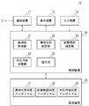
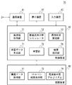
- FIG. 2 shows the configuration of the fluid leakage detection device 10 according to the first embodiment.
- the fluid leakage detection device 10 includes a communication device 11, a display device 12, an input device 13, a control device 20, and a storage device 30.
- the communication device 11 controls wireless or wired communication.
- the communication device 11 transmits / receives data to / from the sensor 5 and the learning device 40 via the Internet 2.
- the display device 12 displays the display image generated by the control device 20.
- the input device 13 inputs an instruction to the control device 20.
- the storage device 30 stores data and computer programs used by the control device 20.
- the storage device 30 includes a leakage situation determination algorithm 31, an influence range determination algorithm 32, and a correspondence content determination algorithm 33.
- the control device 20 includes an actual measurement value acquisition unit 21, a leakage status determination unit 22, an influence range determination unit 23, a response content determination unit 24, and a presentation unit 25. These components are realized by a CPU, a memory, a program loaded in the memory, etc. of an arbitrary computer in terms of hardware components. Here, the functional blocks realized by their cooperation are illustrated. Therefore, it will be understood by those skilled in the art that these functional blocks can be realized in various forms by only hardware, only software, or a combination thereof.
- the actual measurement value acquisition unit 21 acquires the value of the detection target amount detected by the plurality of sensors 5.
- the detection target amount is the concentration of a predetermined type of gas detected by the gas concentration sensor, the intensity of infrared rays imaged by an infrared camera, or the like.
- the leakage status determination unit 22 determines the leakage status such as the position, type, direction, and amount of the gas leakage source in the plant 3 based on the distribution of the detection target amount values acquired by the measured value acquisition unit 21. Although the leakage status determination unit 22 may determine the leakage status by a statistical method or the like based on the distribution of the detection target amounts detected by the plurality of sensors 5, in the present embodiment, the learning device 40 performs learning. The leak status is determined using the leak status determination algorithm 31 described above.
- the leak condition determination algorithm 31 inputs the value of the detection target amount detected by the plurality of sensors 5, and outputs parameters indicating the leak condition such as the position of the fluid leak source, the leak direction, and the leak amount.
- the influence range determination unit 23 positions the fluid leakage source based on the distribution of the values of the detection target amount acquired by the actual measurement value acquisition unit 21 or the fluid leakage state determined by the leakage state determination unit 22. When identifying a building segment and inferring that the effects of the leaking fluid do not stop at the leaking source segment, the effects of diffusion of the leaking fluid, ignition, fire, explosion, etc. due to the leaking fluid Existence and range are judged.
- the influence range determination unit 23 may determine the influence range according to a rule-based determination criterion based on the distribution of the value of the detection target amount, the leakage state, or the like, but in the present embodiment, the learning device 40 learns.
- the influence range determination algorithm 32 is used to determine the influence range.
- the influence range determination algorithm 32 inputs the value of the detection target amount detected by the plurality of sensors 5, the parameter indicating the leakage situation determined by the leakage situation determination unit 22, and the like to determine the parameter indicating the influence range of the fluid leakage. Output.
- the correspondence content determination unit 24 determines the distribution of the value of the detection target amount acquired by the actual measurement value acquisition unit 21, the leakage status of the fluid determined by the leakage status determination unit 22, or the fluid determined by the influence range determination unit 23. Based on the range of influence due to leakage, the content and range of response such as control of the leakage source or ignition source, control of fire extinguishing equipment, emergency shutoff control of fluid valve, depressurization control, etc. are determined.
- the handling content determination unit 24 may determine the handling content and the handling range according to a rule-based determination criterion based on the distribution of the value of the detection target amount, the leakage status, the influence range, etc.
- the corresponding content and the corresponding range are determined by using the corresponding content determination algorithm 33 learned by the learning device 40.
- the correspondence content determination algorithm 33 is a parameter indicating the value of the detection target amount detected by the plurality of sensors 5, the parameter indicating the leakage status determined by the leakage status determination unit 22, and the parameter indicating the influence range determined by the influence range determination unit 23. Etc. is input and the parameters indicating the corresponding content and the corresponding range are output.
- the presentation unit 25 includes the fluid leakage status determined by the leakage status determination unit 22, the influence range due to the fluid leakage determined by the influence range determination unit 23, the response content and response determined by the response content determination unit 24.
- the range and the like are displayed on the display device 12.
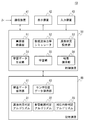
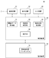
- FIG. 3 shows the configuration of the learning device according to the first embodiment.
- the learning device 40 includes a communication device 41, a display device 42, an input device 43, a control device 50, and a storage device 60.
- the communication device 41 controls wireless or wired communication.
- the communication device 41 transmits / receives data to / from the sensor 5, the fluid leak detection device 10, and the like via the Internet 2.
- the display device 42 displays the display image generated by the control device 50.
- the input device 43 inputs an instruction to the control device 50.
- the storage device 60 stores data and computer programs used by the control device 50.
- the storage device 60 includes a structural data holding unit 61, a sensor position data holding unit 62, a leakage status determination algorithm 31, an influence range determination algorithm 32, and a corresponding content determination algorithm 33.
- the structure data holding unit 61 holds structure data representing the structure of the plant 3.
- the sensor position data holding unit 62 holds data indicating the positions of a plurality of virtual sensors virtually installed in the plant represented by the structure data held by the structure data holding unit 61.
- the plurality of virtual sensors are virtually installed at the same positions as the installation positions of the plurality of sensors 5 installed in the actual plant 3.
- the control device 50 includes an actual measurement value acquisition unit 51, a computational fluid dynamics simulator 52, a leakage status setting unit 53, a learning data generation unit 54, a learning unit 55, and a result presentation unit 56. These functional blocks can also be realized in various forms by only hardware, only software, or a combination thereof.
- the actual measurement value acquisition unit 51 determines the value of the detection target amount detected by the plurality of sensors 5 when the gas leaks in the plant 3 and the parameter indicating the leakage situation at that time, the leakage situation determination algorithm 31, the influence range determination. It is acquired as learning data for learning the algorithm 32 and the correspondence content determination algorithm 33.
- a fluid such as a gas rarely leaks in the actual plant 3, and it is difficult to experiment the leak situation when the gas leaks in the plant 3. Therefore, there are few actual measurement values that can be used as learning data. Limited to Therefore, in the present embodiment, the learning situation is created by reproducing the leakage situation when the fluid leaks under various conditions in the plant 3 by the computational fluid dynamics simulator 52.
- the computational fluid dynamics simulator 52 uses the structural data of the building held in the structural data holding unit 61 to simulate the behavior of the leaked fluid in the building.
- the structure data holding unit 61 divides a building into a plurality of calculation grids, for example, and holds structure data such as the coordinates of the center point, volume, range, and density for each calculation grid.
- the density is the ratio of the length or volume of the structures included in the calculation grid to the volume of the calculation grid.
- the shape of the calculation grid may be a rectangular parallelepiped, a regular tetrahedron, or any other shape.
- the structure data holding unit 61 may hold three-dimensional shape data representing a three-dimensional shape of a building, or may hold structure data of any format that can be used by the computational fluid dynamics simulator 52.
- the structure data holding unit 61 may hold the shape, arrangement position, quantity, etc. of equipment, pipes, frames, etc. installed in the plant 3.
- the computational fluid dynamics simulator 52 obtains an approximate solution of the flow equation for each calculation grid at predetermined time intervals in the leak status set by the leak status setting unit 53, and determines the fluid pressure, flow velocity, density, etc. in each calculation grid. To calculate.
- the computational fluid dynamics simulator 52 simulates the behavior of the fluid from the start of fluid leakage until a predetermined time has elapsed. This makes it possible to accurately reproduce situations such as interference and diffusion with various structures installed in a building when fluid leaks from equipment or pipes that contain flammable or toxic gases. it can.
- the leak status setting unit 53 sets the leak status of the fluid simulated by the computational fluid dynamics simulator 52.
- the leak status setting unit 53 sets parameters indicating the leak status such as the position of the leak source, the opening area, the opening shape, the type of leaked material, the composition, the temperature, the leak direction, the leak rate, the leak amount, and the leak period.
- Parameters such as parameters indicating wind conditions such as wind speed, wind direction, and turbulence of airflow, parameters indicating weather conditions such as temperature, atmospheric pressure, humidity, weather, atmospheric stability, and parameters indicating topography, surface condition, etc. Set.
- the leakage status setting unit 53 uses the leakage status that is considered to have a relatively high possibility of occurring in the plant 3 and the leakage status that is considered to have a high degree of risk and severity when it occurs. May be set preferentially, and those leakage situations may be learned preferentially.
- the result presentation unit 56 displays the leakage status of the fluid simulated by the computational fluid dynamics simulator 52 on the display device 42.
- the result presentation unit 56 may display, for example, an animation of how the fluid leaked from the leak source diffuses.
- the result presentation unit 56 generates an image of the plant 3 by setting an arbitrary viewpoint position and a line-of-sight direction and rendering the structure data held in the structure data holding unit 61, and the generated image of the plant 3
- the simulation result of the fluid leakage state may be displayed in a superimposed manner. Further, the result presentation unit 56 may change the display color depending on the concentration and type of the fluid. As a result, the behavior of the fluid outside the detection range of the gas concentration sensor or the infrared camera can be visualized.
- the result presentation unit 56 may display the gas concentration distribution in any two-dimensional cross section.
- the result presentation unit 56 may display an image of the gas cloud viewed from an arbitrary viewpoint position in an arbitrary line-of-sight direction.
- the result presentation unit 56 may calculate an integrated value based on the gas concentration on the optical path and the length of the gas cloud viewed in the line-of-sight direction from the viewpoint position, and display the calculated integrated value in an arbitrary two-dimensional cross section.
- the learning data generation unit 54 generates learning data for learning the leakage status determination algorithm 31, the influence range determination algorithm 32, and the corresponding content determination algorithm 33 based on the simulation result by the computational fluid dynamics simulator 52.
- the learning data generation unit 54 may generate the gas concentration value detected by the gas concentration sensor as learning data, or may generate the pixel value of the image captured by the infrared camera as learning data.
- the learning data generation unit 54 is detected by each of the virtual gas concentration sensors at the installation position held by the sensor position data holding unit 62. Then, the time change of the value of the gas concentration estimated to be calculated is calculated, and a pair of the value and the parameter indicating the leakage situation is generated as learning data.
- the learning data generating unit 54 is estimated to be imaged by each of the virtual infrared cameras at the installation positions held by the sensor position data holding unit 62.
- the time change of the pixel value of the image is calculated, and a set of those values and the parameter indicating the leakage situation is generated as learning data.
- the learning data generation unit 54 may calculate, as a pixel value, an integrated value of the gas concentration on the optical path and the length of the gas cloud viewed from the installation position of the infrared camera in the line-of-sight direction of the infrared camera.
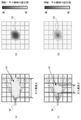
- FIG. 4 shows an example of learning data generated by the learning data generation unit 54.
- FIG. 4A and FIG. 4C show simulation results by the computational fluid dynamics simulator 52.
- the leaked gas diffuses and a gas cloud 63 is formed.
- the learning data generation unit 54 sets the viewpoint position and the line-of-sight direction of the virtual infrared camera 64, and calculates the integrated value based on the gas concentration on the optical path and the length of the gas cloud viewed in the line-of-sight direction from the viewpoint position. , An image estimated to be picked up by an infrared camera installed at the viewpoint position is generated.
- FIGS. 4B and 4D show images generated by the learning data generating unit 54. Although the gas cloud 63 is imaged in both images, the gas cloud 63 in FIG.
- the learning data generation unit 54 sets the viewpoint position of the virtual infrared camera 64 at a plurality of installation positions held by the sensor position data holding unit 62, generates a large number of such images, and sets a parameter indicating the leakage situation. And learning data. Thereby, it is possible to learn the relationship between the image captured by the infrared camera and the parameter indicating the leakage situation.
- the learning data generation unit 54 may generate another parameter regarding leakage gas as learning data instead of or in addition to the gas concentration at each sensor position or the pixel value of the infrared image.
- the distribution of the gas concentration on an arbitrary two-dimensional cross section that crosses the gas cloud, the size of the gas cloud, the spatial or temporal derivative of the gas concentration or pixel value, the distribution of the wind speed or the wind direction, the equivalent stoichiometric gas concentration A value or distribution may be generated as learning data.
- the leakage status determination algorithm 31, the influence range determination algorithm 32, and the corresponding content determination algorithm 33 may be a neural network that inputs these values to the input layer, and the fluid leakage detection device 10 acquires the measured value. You may calculate these values based on the value of the detection object amount acquired by the part 21, and may input them into the leak condition determination algorithm 31, the influence range determination algorithm 32, and the correspondence content determination algorithm 33.
- the learning data generation unit 54 calculates the ignition possibility based on the concentration and temperature of the combustible gas in order to generate the learning data for learning the influence range determination algorithm 32, and the ignition possibility is a predetermined value or more.
- the range of may be the influence range.
- the concentration of the toxic gas may be compared with the limit amount, and the range in which the concentration of the toxic gas exceeds the limit amount may be the influence range.
- the gas concentration is corrected by the combustion characteristic values such as laminar burning velocity according to the gas concentration at each point in the gas cloud The integrated value may be calculated.
- the learning data generation unit 54 causes the computational fluid dynamics simulator 52 to further simulate the fluid leakage state when the predetermined correspondence content is executed.
- the quality of the correspondence may be determined based on the simulation result. For example, the fluid diffusion state when the fire door is closed at a predetermined timing is simulated by the computational fluid dynamics simulator 52, and the subsequent fluid diffusion state is compared with the fluid diffusion state when the fire door is not closed. By doing so, it may be determined whether the fire door is closed at a predetermined timing.
- the result presentation unit 56 may present the simulation result of the computational fluid dynamics simulator 52 to the operator, and acquire the correspondence content and the quality of the correspondence from the operator via the input device 43.
- the learning unit 55 uses the actual measurement value acquired by the actual measurement value acquisition unit 51 or the learning data generated by the learning data generation unit 54 as teacher data, and uses the leakage status determination algorithm 31, the influence range determination algorithm 32, and the corresponding contents.
- the determination algorithm 33 is learned by deep learning with a teacher.
- the learning unit 55 adjusts the weights of the intermediate layer of the neural network according to the input data and the output data included in the teacher data, so that the leakage status determination algorithm 31, the influence range determination algorithm 32, and the corresponding content determination algorithm 33 are determined. learn.
- the learned leakage situation determination algorithm 31, the influence range determination algorithm 32, and the corresponding content determination algorithm 33 are provided to the fluid leakage detection device 10.
- the learning unit 55 may learn the correspondence content determination algorithm 33 by reinforcement learning.
- the learning unit 55 causes the computational fluid dynamics simulator 52 to simulate the fluid leakage situation when various countermeasures are executed at various timings, and the fluid leakage amount and the leakage are higher than when the countermeasure is not executed.
- the correspondence content determination algorithm 33 may be learned by reinforcement learning with a reward that the range or the influence range is reduced.
- the fluid leakage detection device 10 may display the leakage behavior of the fluid on the display device 12 when the fluid leakage is detected.
- the fluid leakage detection device 10 may display the fluid leakage behavior from the start of leakage to the present time on the display device 12, or may display the fluid leakage behavior predicted in the future on the display device 12.
- the fluid leakage detection device 10 may acquire and display a moving image showing the fluid leakage behavior from the learning device 40, or have a configuration for generating a moving image showing the fluid leakage behavior. Good.
- the fluid leak detection device 10 may include a structural data holding unit 61, a computational fluid dynamics simulator 52, and a leak status setting unit 53.
- the leak status determination unit 22 of the fluid leak detection apparatus 10 refers to a leak status database that stores a large number of sets of gas concentration distribution, an image of an infrared camera, and the like and parameters indicating the leak status, instead of the leak status determination algorithm 31.
- the leakage status may be determined by doing so.
- the leakage status determination unit 22 searches the leakage status database for a gas concentration distribution, an infrared camera image, or the like that matches or is similar to the distribution of the detection target amount values acquired by the actual measurement value acquisition unit 21.
- the leakage status may be determined.
- the leakage status determination unit 22 may search the leakage status database using an image matching technique or the like.
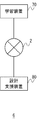
- FIG. 5 shows the overall configuration of the design support system according to the second embodiment.
- the design support system 6 uses a learning device 70 that learns a risk determination algorithm for determining the risk of fluid leakage from factors such as the structure of the plant, and the risk determination algorithm learned by the learning device 70. And a design support device 80 for supporting the plant design.
- the learning device 70 and the design support device 80 are connected by the Internet 2.
- FIG. 6 shows the configuration of the learning device according to the second embodiment.
- the learning device 70 includes a learning data generation unit 71 and a learning unit 72 instead of the learning data generation unit 54 and the learning unit 55 of the learning device 40 according to the first embodiment shown in FIG. Further, in place of the sensor position data holding unit 62, the leakage status determination algorithm 31, the influence range determination algorithm 32, and the corresponding content determination algorithm 33, a simulation result holding unit 73 and a risk determination algorithm 74 are provided. Other configurations and operations are similar to those of the first embodiment.
- the simulation result holding unit 73 holds the simulation result of the computational fluid dynamics simulator 52.
- the simulation result holding unit 73 may hold a simulation result based on the structure of a plant that is a target for design support, or may hold a simulation result based on the structures of a plurality of plants.
- the learning data generation unit 71 evaluates the risk of fluid leakage from the simulation result stored in the simulation result storage 73 according to a predetermined standard, and evaluates the evaluated risk and the structure of the plant in the simulation. The learning data for learning the correlation between the factors is generated.
- the learning data generation unit 71 determines the distribution of the gas concentration on an arbitrary two-dimensional cross section that crosses the gas cloud, the size of the gas cloud, the spatial or temporal derivative of the gas concentration or pixel value, and the equivalent stoichiometric gas concentration value. Or, the gas concentration is corrected by the combustion characteristic values such as distribution, concentration and temperature of flammable gas, ignitability, concentration of toxic gas, and laminar burning velocity according to gas concentration at each point in the gas cloud. The risk may be evaluated based on the integrated value integrated over the entire cloud, the range of influence of the leaked fluid, and the like.
- the factors such as the structure include, for example, the type and material of the structure to be arranged, the physical quantity such as area, volume, density, operating temperature, the density, and the type, amount and temperature of the fluid that can exist inside. It may be.
- the learning unit 72 uses the learning data generated by the learning data generation unit 71 to learn the risk determination algorithm 74.
- the risk determination algorithm 74 may be, for example, a neural network that inputs the values of a plurality of factors that can be extracted from the structural data of the plant and outputs the risk of fluid leakage, or the values of the plurality of factors. May be a mathematical expression expressing the risk level as a variable, or may be an algorithm of any format capable of determining the risk level from the values of a plurality of factors.
- the learning unit 72 may learn the risk determination algorithm 74 by using any technique such as data mining, logistic regression analysis, multivariate analysis, unsupervised machine learning, and supervised machine learning. For example, the intermediate layer of the neural network may be adjusted so that the evaluated risk level is output when the values of a plurality of factors are input for each simulation result.
- the regression coefficient in the regression equation may be calculated by logistic regression analysis.
- FIG. 7 shows the configuration of the design support device according to the second embodiment.
- the design support device 80 according to the second embodiment includes a communication device 81, a display device 82, an input device 83, a control device 90, and a storage device 84.
- the communication device 81 controls wireless or wired communication.
- the communication device 81 transmits / receives data to / from the learning device 70 or the like via the Internet 2.
- the display device 82 displays the display image generated by the control device 90.
- the input device 83 inputs an instruction to the control device 90.
- the storage device 84 stores data and computer programs used by the control device 90.
- the storage device 84 includes a risk determination algorithm 74.
- the control device 90 includes a structure data acquisition unit 91, a risk determination unit 92, a design change recommendation unit 93, and a presentation unit 94. These configurations can also be realized in various forms by only hardware, only software, or a combination thereof.
- the structure data acquisition unit 91 acquires structure data representing the structure of the plant.
- the structure data acquisition unit 91 may acquire CAD data of a plant under design, or may acquire CAD data of a constructed plant or three-dimensional image data.
- the risk determination unit 92 determines the risk of the plant by the risk determination algorithm 74 based on the structure data acquired by the structure data acquisition unit 91.
- the risk determination unit 92 calculates the value of the factor to be input to the risk determination algorithm 74 based on the structural data, and inputs the calculated value of the factor to the risk determination algorithm 74 to determine the risk.
- the risk degree determination unit 92 may divide the plant into a plurality of areas and determine the risk degree for each area.
- the design change recommendation unit 93 recommends a plant design change when the risk level judged by the risk level judgment unit 92 meets a predetermined condition.
- the design change recommending unit 93 may recommend a plant design change when the risk is higher than a predetermined value.
- the design change recommendation unit 93 may recommend the design change for each area.
- the design change recommending section 93 arranges the sensor 5 in an area where the risk is higher than a predetermined value, changes the arrangement of structures so as to reduce the density of the area where the risk is higher than the predetermined value, and It may be recommended to place a structure or the like for preventing the diffusion of the fluid in a region where the degree is higher than a predetermined value.
- the presentation unit 94 displays the determination result by the risk degree determination unit 92, the design change recommendation by the design change recommendation unit 93, and the like on the display device 82.
- the presentation unit 94 sets an arbitrary viewpoint position and line-of-sight direction and renders the structure data acquired by the structure data acquisition unit 91 to generate an image of the plant, and the risk level is superimposed and displayed on the generated image of the plant. You may. Further, the presentation unit 94 may change the display color depending on the degree of risk. As a result, it is possible to visualize the risk of the plant, and it is possible to accurately support the layout for designing the disaster mitigation plant, the arrangement of the sensors, the risk scenario, the analysis of the impact, the evaluation, and the design.
- a fluid leakage detection system is installed in a building, based on a plurality of sensors for detecting the value of the detection target amount at the installation position, and the value of the detection target amount detected by the plurality of sensors, A fluid leakage detection device for detecting fluid leakage in a building.
- the fluid leakage detection device based on the distribution of the value of the detection target amount acquired by the actual measurement value acquisition unit and the actual measurement value acquisition unit that acquires the value of the detection target amount detected by the plurality of sensors, the fluid in the building And a leakage status determination unit that determines the leakage status of. According to this aspect, it is possible to accurately detect the leakage state of the fluid in the building.
- the leakage status determination unit uses the leakage status determination algorithm that inputs the value of the detection target amount detected by the plurality of sensors, which is learned by machine learning, and outputs the leakage status of the fluid, and determines the leakage status of the fluid. You may judge. According to this aspect, it is possible to improve the accuracy of detecting the fluid leakage state.
- the learning device includes a learning unit that learns a leakage situation determination algorithm by machine learning using the value of the detection target amount detected by each of a plurality of sensors when the fluid leaks from a predetermined position of the building as learning data. You may prepare. According to this aspect, the accuracy of the leakage situation determination algorithm can be improved.
- the learning device is a structure data holding unit that holds the structure data of the building, and a behavior of the fluid in the structure when the fluid leaks from a predetermined position of the building.
- a three-dimensional flow simulator that simulates a three-dimensional flow simulation based on structural data may be further provided.
- the learning unit may learn the leakage situation determination algorithm by machine learning using the value of the detection target amount calculated based on the result of the three-dimensional flow simulation by the three-dimensional flow simulator as learning data. According to this aspect, it is possible to generate and learn a large amount of learning data even in the case where the actual measurement value is small, so that it is possible to improve the accuracy and the learning efficiency of the leakage situation determination algorithm.
- the learning device based on the result of the three-dimensional flow simulation by the sensor position data holding unit that holds the data indicating the installation position of the plurality of sensors, the three-dimensional flow simulator, the installation position held in the sensor position data holding unit
- a learning data generation unit that generates learning data by calculating a value of a detection target amount estimated to be detected by each of a plurality of sensors may be further included.
- the learning unit may learn the leakage status determination algorithm by machine learning using the learning data generated by the learning data generation unit. According to this aspect, the accuracy of the leakage situation determination algorithm can be improved.
- the learning unit calculates the position of the leakage source of the fluid, the type of the fluid, the composition of a plurality of substances constituting the fluid, the leakage amount of the fluid, the leakage direction of the fluid, or the state of the building calculated by the three-dimensional flow simulator.
- the leakage situation determination algorithm may be learned by machine learning using the values of the detection target amounts calculated by a plurality of simulations having different physical quantities representing the environment as learning data. According to this aspect, the accuracy of the leakage situation determination algorithm can be improved.
- the sensor may include a fluid concentration sensor that detects the concentration of the fluid.
- the sensor may include an infrared camera.
- Another aspect of the present invention is a fluid leakage detection device.
- This device is installed in a building, and is acquired by an actual measurement value acquisition unit that acquires the value of the detection target amount detected by a plurality of sensors that detect the value of the detection target amount at the installation position, and the actual measurement value acquisition unit.
- a leakage status determination unit that determines the leakage status of the fluid in the building based on the distribution of the value of the detection target amount. According to this aspect, it is possible to accurately detect the leakage state of the fluid in the building.
- Yet another aspect of the present invention is a learning device.
- This device when the fluid leaks from a predetermined position of the building, a learning data generation unit that generates, as learning data, a value of the detection target amount detected by each of the plurality of sensors installed in the building, Learning to learn a leakage situation determination algorithm that inputs the value of the detection target amount detected by multiple sensors and outputs the position of the fluid leakage source by machine learning using the learning data acquired by the learning data acquisition unit And a section.
- the accuracy of the leakage situation determination algorithm can be improved.
- the present invention can be used for a fluid leakage detection system for detecting fluid leakage in a building.
Landscapes
- Physics & Mathematics (AREA)
- General Physics & Mathematics (AREA)
- Engineering & Computer Science (AREA)
- Theoretical Computer Science (AREA)
- Evolutionary Computation (AREA)
- Computer Hardware Design (AREA)
- General Engineering & Computer Science (AREA)
- Geometry (AREA)
- Artificial Intelligence (AREA)
- Computer Vision & Pattern Recognition (AREA)
- Medical Informatics (AREA)
- Software Systems (AREA)
- Pure & Applied Mathematics (AREA)
- Mathematical Physics (AREA)
- Mathematical Optimization (AREA)
- Mathematical Analysis (AREA)
- Fluid Mechanics (AREA)
- Computing Systems (AREA)
- Algebra (AREA)
- Examining Or Testing Airtightness (AREA)
- Electrically Operated Instructional Devices (AREA)
Abstract
Priority Applications (4)
| Application Number | Priority Date | Filing Date | Title |
|---|---|---|---|
| RU2021113385A RU2759815C1 (ru) | 2018-10-16 | 2019-08-01 | Система обнаружения утечки текучей среды, устройство для обнаружения утечки текучей среды и обучающее устройство |
| AU2019362683A AU2019362683B2 (en) | 2018-10-16 | 2019-08-01 | Fluid leakage detection system, fluid leakage detection device, and learning device |
| US17/231,646 US20210232741A1 (en) | 2018-10-16 | 2021-04-15 | Fluid leakage detection system, fluid leakage detection device, and learning device |
| AU2023202574A AU2023202574B2 (en) | 2018-10-16 | 2023-04-27 | Design support system and learning device |
Applications Claiming Priority (2)
| Application Number | Priority Date | Filing Date | Title |
|---|---|---|---|
| JP2018-195205 | 2018-10-16 | ||
| JP2018195205A JP7232610B2 (ja) | 2018-10-16 | 2018-10-16 | 流体漏洩検知システム、流体漏洩検知装置、設計支援システム、設計支援装置、及び学習装置 |
Related Child Applications (1)
| Application Number | Title | Priority Date | Filing Date |
|---|---|---|---|
| US17/231,646 Continuation US20210232741A1 (en) | 2018-10-16 | 2021-04-15 | Fluid leakage detection system, fluid leakage detection device, and learning device |
Publications (1)
| Publication Number | Publication Date |
|---|---|
| WO2020079920A1 true WO2020079920A1 (fr) | 2020-04-23 |
Family
ID=70283034
Family Applications (1)
| Application Number | Title | Priority Date | Filing Date |
|---|---|---|---|
| PCT/JP2019/030170 Ceased WO2020079920A1 (fr) | 2018-10-16 | 2019-08-01 | Système de détection de fuite de fluide, dispositif de détection de fuite de fluide et dispositif d'apprentissage |
Country Status (5)
| Country | Link |
|---|---|
| US (1) | US20210232741A1 (fr) |
| JP (1) | JP7232610B2 (fr) |
| AU (2) | AU2019362683B2 (fr) |
| RU (1) | RU2759815C1 (fr) |
| WO (1) | WO2020079920A1 (fr) |
Cited By (3)
| Publication number | Priority date | Publication date | Assignee | Title |
|---|---|---|---|---|
| WO2022126092A1 (fr) * | 2020-12-07 | 2022-06-16 | Schlumberger Technology Corporation | Système de détection de fuite de réseau de production de fluide |
| WO2022264604A1 (fr) * | 2021-06-16 | 2022-12-22 | コニカミノルタ株式会社 | Dispositif d'estimation de quantité de caractéristiques de concentration de gaz, procédé d'estimation de quantité de caractéristiques de concentration de gaz, programme et dispositif de génération de modèle d'inférence de quantité de caractéristiques de concentration de gaz |
| CN117290639A (zh) * | 2023-11-24 | 2023-12-26 | 深圳大学 | 相变储能罐中材料泄漏定位检测的方法及系统 |
Families Citing this family (43)
| Publication number | Priority date | Publication date | Assignee | Title |
|---|---|---|---|---|
| CN109215295B (zh) * | 2018-09-11 | 2020-07-14 | 清华大学合肥公共安全研究院 | 燃气泄漏的判断方法、装置及电子设备 |
| CA3155399A1 (fr) * | 2019-11-22 | 2021-05-27 | Wenfeng Peng | Systemes informatiques et procedes d'estimation des changements d'emissions fugitives |
| US11409275B2 (en) * | 2019-12-19 | 2022-08-09 | Talal Ali Ahmad | Systems and methods for predicting environmental conditions |
| US11607654B2 (en) | 2019-12-30 | 2023-03-21 | Marathon Petroleum Company Lp | Methods and systems for in-line mixing of hydrocarbon liquids |
| CA3104319C (fr) | 2019-12-30 | 2023-01-24 | Marathon Petroleum Company Lp | Procedes et systemes de gestion du refoulement dans le melange en conduite de liquides d'hydrocarbures |
| WO2021246130A1 (fr) * | 2020-06-05 | 2021-12-09 | コニカミノルタ株式会社 | Dispositif d'identification d'emplacement de fuite de gaz, système d'identification d'emplacement de fuite de gaz, procédé d'identification d'emplacement de fuite de gaz, dispositif de génération de modèle d'estimation d'emplacement de fuite de gaz, procédé de génération de modèle d'estimation d'emplacement de fuite de gaz et programme associé |
| WO2021246210A1 (fr) * | 2020-06-05 | 2021-12-09 | コニカミノルタ株式会社 | Dispositif de génération de données d'apprentissage automatique, procédé de génération de données d'apprentissage automatique, programme et ensemble de données d'apprentissage |
| JP7750233B2 (ja) * | 2020-06-05 | 2025-10-07 | コニカミノルタ株式会社 | ガス移動推測装置、ガス移動推測方法、推測モデル生成装置、推測モデル生成方法、および、プログラム |
| US20230351568A1 (en) * | 2020-06-10 | 2023-11-02 | Konica Minolta, Inc. | Reflection-component-reduced image generating device, reflection component reduction inference model generating device, reflection-component-reduced image generating method, and program |
| WO2022004461A1 (fr) * | 2020-07-03 | 2022-01-06 | コニカミノルタ株式会社 | Dispositif d'estimation de région de gaz, procédé d'estimation de région de gaz, dispositif de génération de modèle d'apprentissage, procédé de génération de modèle d'apprentissage et programme |
| KR102644672B1 (ko) * | 2020-07-14 | 2024-03-08 | (주)에이엘포스 | 냉매 누액 감지 방법 및 장치 |
| KR102516839B1 (ko) * | 2020-08-31 | 2023-03-30 | 이용준 | 누액감지 시스템 및 방법 |
| EP4224452A4 (fr) * | 2020-09-29 | 2024-03-06 | Sony Semiconductor Solutions Corporation | Système de traitement d'informations et procédé de traitement d'informations |
| KR102413399B1 (ko) * | 2020-12-22 | 2022-06-28 | 전북대학교산학협력단 | 기계 학습 기반의 해양 플랜트 파이프라인 누출 진단 시스템 |
| CN113029454B (zh) * | 2021-02-03 | 2023-02-28 | 北京戴纳实验科技有限公司 | 室内气体泄漏监控方法及系统 |
| US12012883B2 (en) | 2021-03-16 | 2024-06-18 | Marathon Petroleum Company Lp | Systems and methods for backhaul transportation of liquefied gas and CO2 using liquefied gas carriers |
| US11578836B2 (en) | 2021-03-16 | 2023-02-14 | Marathon Petroleum Company Lp | Scalable greenhouse gas capture systems and methods |
| US11655940B2 (en) | 2021-03-16 | 2023-05-23 | Marathon Petroleum Company Lp | Systems and methods for transporting fuel and carbon dioxide in a dual fluid vessel |
| US11578638B2 (en) | 2021-03-16 | 2023-02-14 | Marathon Petroleum Company Lp | Scalable greenhouse gas capture systems and methods |
| JP7248823B1 (ja) | 2021-06-09 | 2023-03-29 | 千代田化工建設株式会社 | 流体状態推定システム、学習装置、学習プログラム、推定装置、及び推定プログラム |
| AU2022291371A1 (en) | 2021-06-10 | 2024-01-25 | Iot Technologies Llc | Devices, systems and methods for detecting leaks and measuring |
| US12129559B2 (en) | 2021-08-26 | 2024-10-29 | Marathon Petroleum Company Lp | Test station assemblies for monitoring cathodic protection of structures and related methods |
| US12043905B2 (en) | 2021-08-26 | 2024-07-23 | Marathon Petroleum Company Lp | Electrode watering assemblies and methods for maintaining cathodic monitoring of structures |
| US12180597B2 (en) | 2021-08-26 | 2024-12-31 | Marathon Petroleum Company Lp | Test station assemblies for monitoring cathodic protection of structures and related methods |
| US11447877B1 (en) | 2021-08-26 | 2022-09-20 | Marathon Petroleum Company Lp | Assemblies and methods for monitoring cathodic protection of structures |
| CN114170552A (zh) * | 2021-12-09 | 2022-03-11 | 上海谱盟光电科技有限公司 | 基于红外热成像的天然气泄漏实时预警方法及系统 |
| WO2023175735A1 (fr) * | 2022-03-15 | 2023-09-21 | 日本電気株式会社 | Procédé d'observation de vapeur d'eau |
| WO2023175734A1 (fr) * | 2022-03-15 | 2023-09-21 | 日本電気株式会社 | Procédé d'observation de vapeur d'eau |
| US11686070B1 (en) | 2022-05-04 | 2023-06-27 | Marathon Petroleum Company Lp | Systems, methods, and controllers to enhance heavy equipment warning |
| US12614270B2 (en) | 2022-07-25 | 2026-04-28 | Clean Connect Ai, Inc. | Machine learning system for natural gas leak detection |
| JP2024033396A (ja) * | 2022-08-30 | 2024-03-13 | 三菱重工業株式会社 | 情報処理装置、情報処理方法、およびプログラム |
| JP7805278B2 (ja) * | 2022-12-20 | 2026-01-23 | 三菱重工業株式会社 | モニタリングシステム、ガス漏洩通知方法及びプログラム |
| US12012082B1 (en) | 2022-12-30 | 2024-06-18 | Marathon Petroleum Company Lp | Systems and methods for a hydraulic vent interlock |
| US12006014B1 (en) | 2023-02-18 | 2024-06-11 | Marathon Petroleum Company Lp | Exhaust vent hoods for marine vessels and related methods |
| US12043361B1 (en) | 2023-02-18 | 2024-07-23 | Marathon Petroleum Company Lp | Exhaust handling systems for marine vessels and related methods |
| CN115952926B (zh) * | 2023-03-13 | 2023-05-30 | 北京理工大学 | 危险气体扩散范围预测方法、系统、电子设备及存储介质 |
| WO2024206701A1 (fr) * | 2023-03-28 | 2024-10-03 | Iot Technologies Llc | Dispositifs, systèmes et procédés de détection de fuites et de mesure d'utilisation |
| US12297965B2 (en) | 2023-08-09 | 2025-05-13 | Marathon Petroleum Company Lp | Systems and methods for mixing hydrogen with natural gas |
| US12590859B2 (en) | 2023-08-30 | 2026-03-31 | Deere & Company | Fob geometry for leak detection in mobile equipment |
| US12597151B2 (en) | 2023-09-18 | 2026-04-07 | Marathon Petroleum Company Lp | Systems and methods to determine vegetation encroachment along a right-of-way |
| JP2025145671A (ja) * | 2024-03-22 | 2025-10-03 | 三菱重工エンジン&ターボチャージャ株式会社 | ガス漏洩検知方法及びガス漏洩検知システム |
| WO2025208091A1 (fr) * | 2024-03-28 | 2025-10-02 | Iot Technologies Llc | Dispositifs, systèmes et procédés de détection de fuites et de mesure d'utilisation |
| US20250314550A1 (en) * | 2024-04-08 | 2025-10-09 | Kotleak Ltd. | Systems and methods for leakage detection, prevention, and mitigation |
Citations (3)
| Publication number | Priority date | Publication date | Assignee | Title |
|---|---|---|---|---|
| JPH05231979A (ja) * | 1991-03-05 | 1993-09-07 | Mitsui Toatsu Chem Inc | ガス、蒸気等の漏洩検知システム、風向・風速測定方法および風向・風速測定装置 |
| JP2000346796A (ja) * | 1999-06-02 | 2000-12-15 | Nec San-Ei Instruments Ltd | ガス可視化装置及びガス可視化方法 |
| JP2018077120A (ja) * | 2016-11-09 | 2018-05-17 | エヌ・ティ・ティ・アドバンステクノロジ株式会社 | 判定装置、判定方法及び学習装置 |
Family Cites Families (20)
| Publication number | Priority date | Publication date | Assignee | Title |
|---|---|---|---|---|
| JPS6165129A (ja) * | 1984-09-07 | 1986-04-03 | Mitsubishi Heavy Ind Ltd | 流体の漏洩検知システム |
| JP2687466B2 (ja) * | 1988-08-09 | 1997-12-08 | 日揮株式会社 | ガスの漏洩場所を推定する方法 |
| JP2736669B2 (ja) * | 1989-01-20 | 1998-04-02 | 日揮株式会社 | ガスの漏洩場所および漏洩量を推定する方法 |
| JP3025503B2 (ja) * | 1989-01-20 | 2000-03-27 | 日揮株式会社 | 漏洩ガスの拡散領域を予測する方法 |
| JPH05172689A (ja) * | 1991-12-26 | 1993-07-09 | Hitachi Ltd | 漏洩検出器 |
| JPH0843239A (ja) * | 1994-07-27 | 1996-02-16 | Chiyoda Corp | 障害物を考慮したガス漏洩領域及びガス漏洩量の推定方法 |
| JPH11241376A (ja) * | 1998-02-25 | 1999-09-07 | Daiwa House Ind Co Ltd | 漏水検知装置 |
| JP4405066B2 (ja) * | 2000-09-28 | 2010-01-27 | 株式会社東芝 | 流体漏洩検知システム |
| JP3970140B2 (ja) | 2002-09-10 | 2007-09-05 | 三菱重工業株式会社 | プラント安全管理システム、および同システムにおけるガス濃度監視方法、ならびにガス濃度監視プログラム |
| JP4381316B2 (ja) | 2004-01-27 | 2009-12-09 | 三菱重工業株式会社 | 漏洩ガス検知方法及び漏洩ガス検知装置 |
| US20060191323A1 (en) * | 2005-02-25 | 2006-08-31 | Michael Garabedian | Automated system for detection and control of water leaks, gas leaks, and other building problems |
| JP2008547105A (ja) | 2005-06-24 | 2008-12-25 | エルウィン シュー シェン ホワ | 緊急通知システム |
| US7528711B2 (en) * | 2005-12-19 | 2009-05-05 | Lawrence Kates | Portable monitoring unit |
| KR100894430B1 (ko) * | 2008-11-11 | 2009-04-22 | 시스템디엔디(주) | 초음파, 음향 및 온도변화를 이용한 밸브의 유체누설 측정장치 및 이를 이용한 유체누설 측정방법 |
| EP2599031A4 (fr) * | 2010-07-29 | 2014-01-08 | Exxonmobil Upstream Res Co | Procédés et systèmes pour une simulation de flux par apprentissage automatique |
| JP5473888B2 (ja) | 2010-12-22 | 2014-04-16 | 三菱重工業株式会社 | 漏洩検出システム |
| JP6492612B2 (ja) | 2014-12-16 | 2019-04-03 | コニカミノルタ株式会社 | 漏洩ガス検出装置および漏洩ガス検出方法 |
| US20160356666A1 (en) * | 2015-06-02 | 2016-12-08 | Umm Al-Qura University | Intelligent leakage detection system for pipelines |
| ES2906411T3 (es) * | 2015-06-29 | 2022-04-18 | Suez Groupe | Procedimiento de detección de anomalías en un sistema de distribución de agua |
| KR102529696B1 (ko) * | 2016-07-14 | 2023-05-10 | 에스케이하이닉스 주식회사 | 메모리 시스템 및 메모리 시스템의 동작 방법 |
-
2018
- 2018-10-16 JP JP2018195205A patent/JP7232610B2/ja active Active
-
2019
- 2019-08-01 RU RU2021113385A patent/RU2759815C1/ru active
- 2019-08-01 AU AU2019362683A patent/AU2019362683B2/en active Active
- 2019-08-01 WO PCT/JP2019/030170 patent/WO2020079920A1/fr not_active Ceased
-
2021
- 2021-04-15 US US17/231,646 patent/US20210232741A1/en active Pending
-
2023
- 2023-04-27 AU AU2023202574A patent/AU2023202574B2/en active Active
Patent Citations (3)
| Publication number | Priority date | Publication date | Assignee | Title |
|---|---|---|---|---|
| JPH05231979A (ja) * | 1991-03-05 | 1993-09-07 | Mitsui Toatsu Chem Inc | ガス、蒸気等の漏洩検知システム、風向・風速測定方法および風向・風速測定装置 |
| JP2000346796A (ja) * | 1999-06-02 | 2000-12-15 | Nec San-Ei Instruments Ltd | ガス可視化装置及びガス可視化方法 |
| JP2018077120A (ja) * | 2016-11-09 | 2018-05-17 | エヌ・ティ・ティ・アドバンステクノロジ株式会社 | 判定装置、判定方法及び学習装置 |
Cited By (6)
| Publication number | Priority date | Publication date | Assignee | Title |
|---|---|---|---|---|
| WO2022126092A1 (fr) * | 2020-12-07 | 2022-06-16 | Schlumberger Technology Corporation | Système de détection de fuite de réseau de production de fluide |
| WO2022264604A1 (fr) * | 2021-06-16 | 2022-12-22 | コニカミノルタ株式会社 | Dispositif d'estimation de quantité de caractéristiques de concentration de gaz, procédé d'estimation de quantité de caractéristiques de concentration de gaz, programme et dispositif de génération de modèle d'inférence de quantité de caractéristiques de concentration de gaz |
| JPWO2022264604A1 (fr) * | 2021-06-16 | 2022-12-22 | ||
| JP7772067B2 (ja) | 2021-06-16 | 2025-11-18 | コニカミノルタ株式会社 | ガス濃度特徴量推定装置、ガス濃度特徴量推定方法、プログラム、およびガス濃度特徴量推論モデル生成装置 |
| CN117290639A (zh) * | 2023-11-24 | 2023-12-26 | 深圳大学 | 相变储能罐中材料泄漏定位检测的方法及系统 |
| CN117290639B (zh) * | 2023-11-24 | 2024-02-27 | 深圳大学 | 相变储能罐中材料泄漏定位检测的方法及系统 |
Also Published As
| Publication number | Publication date |
|---|---|
| AU2019362683B2 (en) | 2023-05-18 |
| AU2019362683A1 (en) | 2021-05-20 |
| AU2023202574A1 (en) | 2023-05-18 |
| RU2759815C1 (ru) | 2021-11-18 |
| US20210232741A1 (en) | 2021-07-29 |
| JP7232610B2 (ja) | 2023-03-03 |
| JP2020063955A (ja) | 2020-04-23 |
| AU2023202574B2 (en) | 2024-11-14 |
Similar Documents
| Publication | Publication Date | Title |
|---|---|---|
| JP7232610B2 (ja) | 流体漏洩検知システム、流体漏洩検知装置、設計支援システム、設計支援装置、及び学習装置 | |
| US20200320659A1 (en) | Segmentation and prediction of low-level temporal plume patterns | |
| US11409275B2 (en) | Systems and methods for predicting environmental conditions | |
| KR101885350B1 (ko) | 대기오염 통합 관리 시스템 | |
| CN118297377A (zh) | 一种施工现场火灾危险预估方法、介质及系统 | |
| CN110390135B (zh) | 一种提高林火蔓延预测精度的方法 | |
| CN119005068B (zh) | 基于数字孪生的船舶管路泄漏热成像监测系统 | |
| CN116152662A (zh) | 一种森林火灾烟雾探测方法和系统 | |
| CN119598816B (zh) | 隧道流淌火灾的流动燃烧行为的预测方法及装置、设备及介质 | |
| CN118586308B (zh) | 一种基于计算流体力学的气体泄漏红外成像数据集构建方法 | |
| JP7772067B2 (ja) | ガス濃度特徴量推定装置、ガス濃度特徴量推定方法、プログラム、およびガス濃度特徴量推論モデル生成装置 | |
| CN120279677A (zh) | 一种智能巡检系统、方法、设备和存储介质 | |
| CA3156834A1 (fr) | Procede de detection de fuite | |
| US20250077743A1 (en) | A.i. based cbr event source tracking system and controlling method for the same | |
| CN117291293B (zh) | 隧道火场灾情感知和态势发展预测方法 | |
| Hamilton et al. | Visual Twin for Pipeline Leak Detection | |
| CN120471913A (zh) | 羽流模型图像数据增强的气体泄漏视觉检测方法及系统 | |
| CN118709589A (zh) | Gil管廊气体泄漏的仿真反演方法、装置、设备及存储介质 | |
| CN117011793A (zh) | 一种优化后的火灾早期探测方法及其火灾早期探测装置 | |
| WO2024111235A1 (fr) | Procédé d'évaluation de position de point d'observation et système d'évaluation de position de point d'observation | |
| WO2024048065A1 (fr) | Dispositif de traitement d'informations, procédé de traitement d'informations, et programme | |
| Kumar et al. | Long Short-Term Memory Network for High-Fidelity Tracking of Greenhouse Gas Emission | |
| Tan et al. | Characterizing wildfire perimeter polygons from quic-fire | |
| Xu et al. | Underground mine tunnel fire dynamics: Experimental investigation and AI-driven characterization of flame behavior | |
| Fan et al. | A scoring-based approach for monitoring high-pressure ammonia leaks in marine engine rooms |
Legal Events
| Date | Code | Title | Description |
|---|---|---|---|
| 121 | Ep: the epo has been informed by wipo that ep was designated in this application |
Ref document number: 19874670 Country of ref document: EP Kind code of ref document: A1 |
|
| NENP | Non-entry into the national phase |
Ref country code: DE |
|
| ENP | Entry into the national phase |
Ref document number: 2019362683 Country of ref document: AU Date of ref document: 20190801 Kind code of ref document: A |
|
| 122 | Ep: pct application non-entry in european phase |
Ref document number: 19874670 Country of ref document: EP Kind code of ref document: A1 |