WO2020084890A1 - Dispositif d'analyse de rayons x et unité de génération de rayons x - Google Patents
Dispositif d'analyse de rayons x et unité de génération de rayons x Download PDFInfo
- Publication number
- WO2020084890A1 WO2020084890A1 PCT/JP2019/033399 JP2019033399W WO2020084890A1 WO 2020084890 A1 WO2020084890 A1 WO 2020084890A1 JP 2019033399 W JP2019033399 W JP 2019033399W WO 2020084890 A1 WO2020084890 A1 WO 2020084890A1
- Authority
- WO
- WIPO (PCT)
- Prior art keywords
- ray
- target
- plate
- generation unit
- electron beam
- Prior art date
- Legal status (The legal status is an assumption and is not a legal conclusion. Google has not performed a legal analysis and makes no representation as to the accuracy of the status listed.)
- Ceased
Links
Images


Classifications
-
- G—PHYSICS
- G21—NUCLEAR PHYSICS; NUCLEAR ENGINEERING
- G21K—HANDLING OF PARTICLES OR IONISING RADIATION NOT OTHERWISE PROVIDED FOR; IRRADIATION DEVICES; GAMMA RAY OR X-RAY MICROSCOPES
- G21K7/00—Gamma- or X-ray microscopes
-
- G—PHYSICS
- G01—MEASURING; TESTING
- G01N—INVESTIGATING OR ANALYSING MATERIALS BY DETERMINING THEIR CHEMICAL OR PHYSICAL PROPERTIES
- G01N23/00—Investigating or analysing materials by the use of wave or particle radiation, e.g. X-rays or neutrons, not covered by groups G01N3/00 – G01N17/00, G01N21/00 or G01N22/00
- G01N23/22—Investigating or analysing materials by the use of wave or particle radiation, e.g. X-rays or neutrons, not covered by groups G01N3/00 – G01N17/00, G01N21/00 or G01N22/00 by measuring secondary emission from the material
- G01N23/225—Investigating or analysing materials by the use of wave or particle radiation, e.g. X-rays or neutrons, not covered by groups G01N3/00 – G01N17/00, G01N21/00 or G01N22/00 by measuring secondary emission from the material using electron or ion
- G01N23/2251—Investigating or analysing materials by the use of wave or particle radiation, e.g. X-rays or neutrons, not covered by groups G01N3/00 – G01N17/00, G01N21/00 or G01N22/00 by measuring secondary emission from the material using electron or ion using incident electron beams, e.g. scanning electron microscopy [SEM]
- G01N23/2252—Measuring emitted X-rays, e.g. electron probe microanalysis [EPMA]
-
- G—PHYSICS
- G01—MEASURING; TESTING
- G01N—INVESTIGATING OR ANALYSING MATERIALS BY DETERMINING THEIR CHEMICAL OR PHYSICAL PROPERTIES
- G01N23/00—Investigating or analysing materials by the use of wave or particle radiation, e.g. X-rays or neutrons, not covered by groups G01N3/00 – G01N17/00, G01N21/00 or G01N22/00
- G01N23/22—Investigating or analysing materials by the use of wave or particle radiation, e.g. X-rays or neutrons, not covered by groups G01N3/00 – G01N17/00, G01N21/00 or G01N22/00 by measuring secondary emission from the material
- G01N23/223—Investigating or analysing materials by the use of wave or particle radiation, e.g. X-rays or neutrons, not covered by groups G01N3/00 – G01N17/00, G01N21/00 or G01N22/00 by measuring secondary emission from the material by irradiating the sample with X-rays or gamma-rays and by measuring X-ray fluorescence
-
- H—ELECTRICITY
- H01—ELECTRIC ELEMENTS
- H01J—ELECTRIC DISCHARGE TUBES OR DISCHARGE LAMPS
- H01J35/00—X-ray tubes
- H01J35/02—Details
- H01J35/04—Electrodes ; Mutual position thereof; Constructional adaptations therefor
- H01J35/08—Anodes; Anti cathodes
- H01J35/112—Non-rotating anodes
- H01J35/116—Transmissive anodes
-
- G—PHYSICS
- G01—MEASURING; TESTING
- G01N—INVESTIGATING OR ANALYSING MATERIALS BY DETERMINING THEIR CHEMICAL OR PHYSICAL PROPERTIES
- G01N2223/00—Investigating materials by wave or particle radiation
- G01N2223/07—Investigating materials by wave or particle radiation secondary emission
- G01N2223/076—X-ray fluorescence
-
- G—PHYSICS
- G01—MEASURING; TESTING
- G01N—INVESTIGATING OR ANALYSING MATERIALS BY DETERMINING THEIR CHEMICAL OR PHYSICAL PROPERTIES
- G01N2223/00—Investigating materials by wave or particle radiation
- G01N2223/07—Investigating materials by wave or particle radiation secondary emission
- G01N2223/079—Investigating materials by wave or particle radiation secondary emission incident electron beam and measuring excited X-rays
-
- G—PHYSICS
- G01—MEASURING; TESTING
- G01N—INVESTIGATING OR ANALYSING MATERIALS BY DETERMINING THEIR CHEMICAL OR PHYSICAL PROPERTIES
- G01N2223/00—Investigating materials by wave or particle radiation
- G01N2223/20—Sources of radiation
- G01N2223/204—Sources of radiation source created from radiated target
-
- G—PHYSICS
- G01—MEASURING; TESTING
- G01N—INVESTIGATING OR ANALYSING MATERIALS BY DETERMINING THEIR CHEMICAL OR PHYSICAL PROPERTIES
- G01N2223/00—Investigating materials by wave or particle radiation
- G01N2223/30—Accessories, mechanical or electrical features
- G01N2223/316—Accessories, mechanical or electrical features collimators
-
- G—PHYSICS
- G21—NUCLEAR PHYSICS; NUCLEAR ENGINEERING
- G21K—HANDLING OF PARTICLES OR IONISING RADIATION NOT OTHERWISE PROVIDED FOR; IRRADIATION DEVICES; GAMMA RAY OR X-RAY MICROSCOPES
- G21K1/00—Arrangements for handling particles or ionising radiation, e.g. focusing or moderating
- G21K1/06—Arrangements for handling particles or ionising radiation, e.g. focusing or moderating using diffraction, refraction or reflection, e.g. monochromators
-
- H—ELECTRICITY
- H01—ELECTRIC ELEMENTS
- H01J—ELECTRIC DISCHARGE TUBES OR DISCHARGE LAMPS
- H01J2235/00—X-ray tubes
- H01J2235/10—Drive means for anode (target) substrate
Definitions
- the present disclosure relates to an X-ray analysis device and an X-ray generation unit.
- An X-ray analyzer is used which detects transmitted X-rays or diffracted X-rays and analyzes the internal composition of the sample and the crystal structure of the sample.
- Patent Document 1 discloses an X-ray analyzer using an X-ray conduit such as a monocapillary or a polycapillary as an X-ray focusing optical system that focuses X-rays and irradiates the sample on the stage. .
- the conventional X-ray analysis apparatus using the X-ray tube performs mapping and the like by moving the stage of the sample table on which the sample is placed, and it takes time to move because the mechanical parts of the stage are moved.
- the present disclosure has been made in view of such circumstances, and an object thereof is to provide an X-ray analysis apparatus and an X-ray generation unit that can shorten the scanning time.
- An X-ray analysis apparatus includes an X-ray generation unit, and the X-ray generation unit includes a target plate having a target that is irradiated with an electron beam from an electron beam source to generate an X-ray, and the target plate.
- An X-ray condensing element that condenses X-rays generated from the target in conjunction with movement; a drive unit that changes the position of the target plate or the X-ray condensing element with respect to the electron beam source;
- the stage includes a stage on which an object to be irradiated, which is irradiated with the X-rays generated by the ray generating unit, is placed, and an X-ray detector that detects fluorescent X-rays emitted from the object to be irradiated.
- An X-ray generation unit collects X-rays generated from the target plate in cooperation with a target plate having a target that is irradiated with an electron beam from an electron beam source to generate X-rays and the movement of the target plate.
- An X-ray condensing element that emits light and a driving unit that changes the position of the target plate or the X-ray condensing element with respect to the electron beam source are provided.
- the X-ray generation unit is a target plate having a target that emits an X-ray by being irradiated with an electron beam from an electron beam source, and an X-ray condensing unit that links the movement of the target plate and condenses the X-ray generated from the target. And an element.
- the target includes, for example, a heavy metal such as rhodium, tungsten, or molybdenum, and can generate X-rays by excitation by electron collision or bremsstrahlung.
- the drive unit changes the position of the target plate or X-ray condensing element with respect to the electron beam source. That is, the drive unit changes the position of the target plate with respect to the electron beam source, thereby changing the position of the X-ray condensing element that is interlocked with the movement of the target plate, and the X-ray condensing element collects the X-ray.
- the position of the focal point of the line is moved vertically and horizontally on the irradiation target.
- the drive unit changes the position of the X-ray condensing element with respect to the electron beam source, thereby changing the position of the target plate that is interlocked with the movement of the X-ray condensing element and condensing with the X-ray condensing element.
- the position of the focused X-ray is moved in the vertical and horizontal directions on the irradiation target. This makes it possible to focus the X-rays only by changing the directions of the small and lightweight target plate and the X-ray condensing element, as compared with the case of moving a stage composed of mechanically large parts in the X and Y directions. Since the object to be irradiated can be scanned, the scanning time can be shortened.
- the X-ray analysis apparatus includes a stage on which an irradiation target that is irradiated with X-rays generated by an X-ray generation unit is placed, and an X-ray detection unit that detects fluorescent X-rays emitted from the irradiation target. .
- the irradiation target can be analyzed based on the fluorescent X-rays (secondary X-rays) detected by the X-ray detection unit.
- the drive unit rotationally drives the target plate, and the X-rays condensed by the X-ray condensing element are vertically and vertically on a plane orthogonal to the X-ray direction. Scan horizontally.
- the drive unit rotates the target plate, and the X-rays collected by the X-ray condensing element scan in the vertical and horizontal directions on the plane orthogonal to the X-ray direction. Since the scanning speed can be increased, the speed at which the mapping image is obtained can be increased, and the analysis processing speed is improved.
- the X-ray analysis apparatus includes an X-ray optical element that parallelizes the X-ray generated from the target between the target plate and the X-ray condensing element.
- An X-ray optical element for collimating the X-rays generated from the target is provided between the target plate and the X-ray condensing element.
- the X-ray optical element is an element for guiding the X-ray generated on the target plate to the X-ray condensing element. Thereby, the X-rays generated on the target plate can be correctly focused on the X-ray focusing element.
- the X-ray condensing element is a Fresnel zone plate.
- the X-ray focusing element is a Fresnel zone plate.
- the Fresnel zone plate is, for example, a plate in which transparent and opaque concentric zones are alternately arranged, and the intervals are narrower toward the outer side in the radial direction from the center of the concentric circle.
- the Fresnel zone plate has a function as a transmission-type non-equidistant diffraction grating in which the X-ray incident on the outside is bent more greatly.
- the Fresnel zone plate can focus X-rays from 0.1 ⁇ m to several tens of nm, so that the X-ray focus size is reduced. Further, since the Fresnel zone plate can be made smaller than the X-ray conduit, it is easy to rotate about the fulcrum.
- the scanning time can be shortened.
- FIG. 1 is a schematic diagram showing an example of the configuration of an X-ray analysis apparatus 100 according to this embodiment.
- the X-ray analysis apparatus 100 includes an optical system container 14, a sample container 15, and an imaging unit 30.
- the X-ray analysis apparatus 100 may include the PC 40.
- An X-ray transmission window 16 is provided between the optical system storage section 14 and the sample storage section 15.
- the electron beam source 10 and the X-ray generation unit 50 are kept in a depressurized state.
- the inside of the sample storage unit 15 may be atmospheric air, but may be depressurized in order to prevent attenuation of fluorescent X-rays (secondary X-rays) emitted from the sample S (irradiation target).
- the optical system container 14 and the sample container 15 may be the same container.
- the optical system housing 14 houses the electron beam source 10, the electron beam controller 11, the X-ray generation unit 50, the energy filter 12, the mirror 13, a part of the X-ray detector 20, and the like.
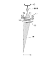
- the X-ray generation unit 50 includes a target plate 52, a capillary plate 54 as an X-ray optical element, a Fresnel zone plate 55 as an X-ray condensing element, a drive unit 53, and the like.
- the target 51 is vapor-deposited.
- a stage 17 on which the sample S is placed is arranged in the sample container 15.
- An imaging unit 30 is arranged on the upper part of one side of the sample storage unit 15.
- the imaging unit 30 is, for example, an optical camera or an optical microscope.
- the PC 40 includes a control unit 41, a calculation unit 42, and a display unit 43, and controls the processing in the X-ray analysis apparatus 100.
- the electron beam source 10 is an electron gun and includes, for example, a filament containing tungsten. When the filament is heated by passing a current through the filament, electrons (thermoelectrons) are emitted from the filament.
- the electron beam control unit 11 includes an anode, a deflection coil, and an electronic lens including a converging lens and an objective lens.
- the electron beam controller 11 changes the traveling direction of the electrons emitted from the electron beam source 10 and accelerates the electrons toward the target 51.
- the electron beam controller 11 is not an essential component.
- the target 51 contains, for example, a heavy metal such as rhodium, tungsten, or molybdenum, and can generate X-rays by excitation by electron collision or bremsstrahlung.
- a heavy metal such as rhodium, tungsten, or molybdenum
- the target plate 52 can be made of a light source material such as beryllium, diamond, or graphite, and can radiate the target 51 as a heat source. Further, in order to reduce the radiant heat, a material having a high infrared reflectance may be coated. Alternatively, a heat radiating sheet may be provided between the target plate 52 and the capillary plate 54.
- the shape of the target plate 52 in plan view can be a circular shape, but is not limited to this and may be, for example, a rectangular shape. Hereinafter, the shape will be described as a circular shape.
- the capillary plate 54 has, for example, a configuration in which a plurality of capillaries each having an optical axis provided in a direction orthogonal to the surface of a circular plate are arranged on the plate in a honeycomb shape, for example.
- a glass material can be used for the capillary plate 54.
- the X-ray generated by the target 51 immediately above the capillary plate 54 passes through the target plate 52, enters the inlet side of the capillary plate 54, is totally reflected inside each capillary, and is emitted in parallel from the output side. .
- the X-rays generated by the target 51 can be made parallel and incident on the Fresnel zone plate 55. That is, the capillary plate 54 is an element for guiding the X-ray generated in the target plate 52 to the Fresnel zone plate 55.
- Fresnel zone plate 55 uses the diffraction phenomenon, and some X-ray condensing elements such as monocapillaries use reflection. Since the diffraction phenomenon and reflection are used, if the angle of the X-ray incident on the X-ray focusing element changes, the X-ray cannot be focused correctly.
- the capillary plate 54 which is an X-ray optical element for collimating X-rays
- the target plate 52 and the Fresnel zone plate 55 X-ray condensing element
- the X-ray generation unit 50 rotates, the X-ray incidence angle between the target plate 52 and the Fresnel zone plate 55 does not change, so that X-rays can be focused correctly.
- the Fresnel zone plate 55 is, for example, a plate in which transparent and opaque concentric zones are alternately arranged, and the intervals are narrower in the outer zones from the center of the concentric circles in the radial direction.
- the Fresnel zone plate 55 has a function as a transmission-type non-equidistant diffraction grating in which the X-rays incident to the outside are bent more greatly.
- the Fresnel zone plate 55 has a long focal length (for example, 500 mm, 800 mm, etc.) depending on the energy of X-rays, the Fresnel zone plate 55 (X-ray generation unit 50) rotates about a predetermined fulcrum.
- the Fresnel zone plate 55 can collect X-rays with a focal size of 0.1 ⁇ m to several tens of nm, so that the focal size of X-rays is smaller than that of an X-ray conduit such as a monocapillary or polycapillary. can do.
- Fresnel zone plate 55 has a longer focal length than an X-ray conduit such as a polycapillary.
- the focal length of an X-ray conduit such as a polycapillary is about 20 mm.
- the Fresnel zone plate 55 is thinner than an X-ray conduit such as a polycapillary, the Fresnel zone plate 55 can be downsized, and the Fresnel zone plate 55 can be rotated with a small driving force.
- the target plate 52 and the Fresnel zone plate 55 with the capillary plate 54 provided therebetween are integrated. Being integrated means that the capillary plate 54 and the Fresnel zone plate 55 move in the same manner in conjunction with the movement of the target plate 52.
- the target plate 52, the capillary plate 54, and the Fresnel zone plate 55 may be fixed with an adhesive or the like, or may be fitted into a frame (not shown). Further, an appropriate fixing method such as winding a tape around the target plate 52, the capillary plate 54, and the Fresnel zone plate 55 to fix the target plate 52, the capillary plate 54, and the Fresnel zone plate 55 can be used. Note that the capillary plate 54 may not be provided.
- the X-ray generation unit 50 can be rotated about a predetermined fulcrum (indicated by symbol P in FIG. 1) by the drive unit 53. That is, by making the integrated target plate 52 and Fresnel zone plate 55 rotatable about a predetermined fulcrum P, the position of the focal point of the X-ray focused by the Fresnel zone plate 55 on the sample S. It can be moved vertically and horizontally. As a result, the X-ray generation unit 50 that is small and lightweight can be rotated about a predetermined fulcrum as compared with the case where a stage composed of mechanically large parts is moved in the vertical and horizontal directions. Can be scanned with the sample S, so that the scanning time can be shortened.
- the position of the fulcrum P is not limited to the position illustrated in FIG.
- the fulcrum P may be on the Fresnel zone plate 55. An appropriate position can be determined according to the arrangement of each part of the device.
- the drive unit 53 can change the position of the target plate 52 or the Fresnel zone plate 55 with respect to the electron beam source 10.
- the drive unit 53 is fixed to the target plate 52 and arranged around the target plate 52, and includes a hollow cylindrical piezoelectric element (piezoelectric element).
- the drive unit 53 may be fixed to the Fresnel zone plate 55.
- a ground electrode (0 V) is provided on the entire inner surface of the piezo element, and a plurality of appropriately divided electrodes are provided on the outer surface of the piezo element. By controlling the voltage applied to each electrode, the piezo element can be partially contracted and extended, and the target plate 52 can be swung about the fulcrum P.
- the entire X-ray generation unit 50 makes the same movement according to the movement of the target plate 52.
- the drive unit 53 is not limited to the piezo element, and may be a unit that can rotate in the X-axis direction and the Y-axis direction around a predetermined fulcrum, and may be, for example, a biaxial rotary stage. .
- the Fresnel zone plate 55 can be made smaller than the X-ray conduit, it is easy to rotate around the fulcrum.
- the energy filter 12 can transmit X-rays of required energy.
- Mirror 13 has a notch in the part where X-rays pass.
- the mirrors 13 may be arranged such that they face each other with a portion through which the X-rays pass, and a required gap is provided.
- the mirror 13 may be made of a material that can transmit X-rays.
- the X-ray detector 20 may be a plurality of X-ray detectors.
- the position where the X-ray strikes on the sample changes.
- the position where the fluorescent X-ray emerges also changes, so the distance between the generation position of the fluorescent X-ray and the X-ray detection unit 20 changes. Therefore, it is preferable to provide a plurality of X-ray detectors, and it is most preferable to use an annular detector in which a plurality of detectors are arranged around a hole through which X-rays pass. Further, the analysis result may be corrected among a plurality of X-ray detectors.
- the control unit 41 rotates the X-ray generation unit 50 about the fulcrum P by outputting a control signal to the drive unit 53. Thereby, the X-ray focus can be moved on the sample S. Further, the control unit 41 can control the operations of the electron beam source 10 and the electron beam control unit 11 to control the output intensity of X-rays. Further, the control unit 41 can control the operations of the stage 17 and the imaging unit 30.
- the calculation unit 42 performs an analysis process based on the intensity data of the fluorescent X-ray spectrum line detected by the X-ray detection unit 20.
- the control unit 41 can display the analysis result of the calculation unit 42 on the display unit 43.
- the display unit 43 can also display the optical image captured by the image capturing unit 30.
- the imaging unit 30 is used to find a measurement point on the sample, and thus, the measurement position can be irradiated with X-rays.
- FIGS. 2A and 2B are schematic diagrams showing an example of how the X-ray generation unit 50 rotates.
- 2A shows a state in which the X-ray generation unit 50 is not rotated
- FIG. 2B shows, for example, an axis through which the X-ray generation unit 50 passes through the fulcrum P (for example, an axis orthogonal to the paper surface: a Y-axis). It shows how to rotate around.
- the X-ray generation unit 50 can also be rotated about an axis passing through the fulcrum P (for example, an axis parallel to the paper surface: the X axis).
- the piezo elements on the one side in the X-axis direction contract.
- the X-ray generation unit 50 can be rotated about the fulcrum P toward one side in the X-axis direction.
- the piezoelectric element on one side in the X-axis direction expands and the other side contracts, so that the fulcrum P is centered.
- the X-ray generation unit 50 can be rotated toward the other side in the X-axis direction. The same applies to rotation in the Y-axis direction.
- FIG. 3 is a schematic diagram showing the moving direction of the X-ray focal point position.
- the focus position of the X-ray is changed to the X-axis direction (for example, horizontal direction) and the Y-axis direction (for example, vertical direction). Can be moved to.
- the focus position of the X-ray may move like the character “NO”.
- the drive unit 53 may be in charge of the movement in the X-axis direction, and the stage 17 may be in charge of the movement in the Y-axis direction, and vice versa. In this case, the structure of the drive unit can be simplified.
- the present embodiment has a configuration in which the target 51 (target plate 52) as the X-ray source and the Fresnel zone plate 55 as the light converging element are integrated and rotated about a predetermined fulcrum.
- the X-ray generation unit 50 rotates about the fulcrum P, the X-rays collected by the Fresnel zone plate 55 scan in the vertical and horizontal directions on the plane orthogonal to the X-ray direction. Since the scanning speed can be increased, the speed at which the mapping image is obtained can be increased, and the analysis processing speed is improved.
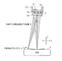
- FIG. 4 is a schematic diagram showing an example of correction of the X-ray focal point position by the X-ray generation unit 50.
- the distance from the fulcrum P to the focal position of the X-ray is R
- the rotation angle of the X-ray generation unit 50 is ⁇ with the Z-axis direction as a reference.
- the X-ray focal point position also draws a circle on the X-axis-Z-axis plane.
- the rotation angle ⁇ is 0, the focus position of the X-ray is on the surface of the sample S, but when the rotation angle ⁇ ( ⁇ 0), the X-ray focal point shifts by R ⁇ sin 2 ⁇ . Therefore, by moving the drive unit 53 along the Z-axis direction according to the rotation angle ⁇ , the focal position of the X-ray can be maintained on the sample surface.
- the stage 17 may be moved along the Z-axis direction instead of moving the driving unit 53.
- the present embodiment it is possible to move the X-ray focal point position simply by rotating the X-ray generation unit 50 about the fulcrum P in the angular direction. Further, conventionally, it took time to perform stage scanning to scan a sample and generate a mapping image (for example, an image showing the analysis result of the sample) while performing the stage scanning. Since it takes time for the stage to reach the position, it takes a long time to analyze the target in such a sample. According to the present embodiment, since the scanning speed is high, the speed at which a mapping image is obtained is high, and especially for samples requiring high analysis speed such as foreign substance inspection, analysis can be performed in a short time. Yes, and very effective.
- Electron beam source 11
- Electron beam control unit 12
- Energy filter 13
- Mirror 14
- Optical system storage unit 15
- Sample storage unit 16
- Stage 20
- X-ray detection unit 30
- Imaging unit 40
- control unit 42
- calculation unit 43
- display unit 50
- X-ray generation unit 51
- target 52
- drive unit 54
- capillary plate 55
Landscapes
- Physics & Mathematics (AREA)
- Health & Medical Sciences (AREA)
- Life Sciences & Earth Sciences (AREA)
- Chemical & Material Sciences (AREA)
- Analytical Chemistry (AREA)
- Biochemistry (AREA)
- General Health & Medical Sciences (AREA)
- General Physics & Mathematics (AREA)
- Immunology (AREA)
- Pathology (AREA)
- Engineering & Computer Science (AREA)
- General Engineering & Computer Science (AREA)
- High Energy & Nuclear Physics (AREA)
- Analysing Materials By The Use Of Radiation (AREA)
Abstract
L'invention concerne un dispositif d'analyse de rayons X et une unité de génération de rayons X qui permettent de réduire le temps de balayage. Le dispositif d'analyse de rayons X comprend l'unité de génération de rayons X. L'unité de génération de rayons X comprend une plaque cible ayant une cible qui est irradiée avec un faisceau d'électrons à partir d'une source de faisceau d'électrons et génère des rayons X, un élément de concentration de rayons X qui se déplace conjointement avec la plaque cible et concentre les rayons X générés par la cible, et une unité d'entraînement pour modifier la position de la plaque cible ou de l'élément de concentration de rayons X par rapport à la source de faisceau d'électrons.
Priority Applications (3)
| Application Number | Priority Date | Filing Date | Title |
|---|---|---|---|
| US17/287,696 US11467107B2 (en) | 2018-10-25 | 2019-08-27 | X-ray analysis apparatus and x-ray generation unit |
| DE112019005321.3T DE112019005321T5 (de) | 2018-10-25 | 2019-08-27 | Röntgenanalyseeinrichtung und röntgenstrahl-erzeugungseinheit |
| JP2020552563A JP7270637B2 (ja) | 2018-10-25 | 2019-08-27 | X線分析装置及びx線発生ユニット |
Applications Claiming Priority (2)
| Application Number | Priority Date | Filing Date | Title |
|---|---|---|---|
| JP2018-201221 | 2018-10-25 | ||
| JP2018201221 | 2018-10-25 |
Publications (1)
| Publication Number | Publication Date |
|---|---|
| WO2020084890A1 true WO2020084890A1 (fr) | 2020-04-30 |
Family
ID=70331317
Family Applications (1)
| Application Number | Title | Priority Date | Filing Date |
|---|---|---|---|
| PCT/JP2019/033399 Ceased WO2020084890A1 (fr) | 2018-10-25 | 2019-08-27 | Dispositif d'analyse de rayons x et unité de génération de rayons x |
Country Status (4)
| Country | Link |
|---|---|
| US (1) | US11467107B2 (fr) |
| JP (1) | JP7270637B2 (fr) |
| DE (1) | DE112019005321T5 (fr) |
| WO (1) | WO2020084890A1 (fr) |
Cited By (2)
| Publication number | Priority date | Publication date | Assignee | Title |
|---|---|---|---|---|
| JPWO2023145236A1 (fr) * | 2022-01-31 | 2023-08-03 | ||
| JP2024001459A (ja) * | 2022-06-22 | 2024-01-10 | 株式会社島津製作所 | 検出方法、および検出装置 |
Families Citing this family (1)
| Publication number | Priority date | Publication date | Assignee | Title |
|---|---|---|---|---|
| CN113764246B (zh) * | 2020-06-03 | 2025-04-18 | 宁波伯锐锶电子束科技有限公司 | 一种显微镜 |
Citations (9)
| Publication number | Priority date | Publication date | Assignee | Title |
|---|---|---|---|---|
| US4519092A (en) * | 1982-10-27 | 1985-05-21 | Albert Richard D | Scanning x-ray spectrometry method and apparatus |
| JPH05273400A (ja) * | 1992-03-25 | 1993-10-22 | Nikon Corp | X線走査装置 |
| JPH08247971A (ja) * | 1995-03-13 | 1996-09-27 | Shimadzu Corp | 蛍光x線分析装置 |
| JP2002071586A (ja) * | 2000-09-01 | 2002-03-08 | Horiba Ltd | 二次元走査x線分析装置 |
| JP2002328102A (ja) * | 2001-04-27 | 2002-11-15 | X-Ray Precision Inc | 走査型x線顕微鏡 |
| JP2005512288A (ja) * | 2001-12-04 | 2005-04-28 | エックス−レイ オプティカル システムズ インコーポレーテッド | 改善された出力安定性を有するx線ソースアセンブリ、およびその流体ストリーム分析の適用 |
| JP2008268105A (ja) * | 2007-04-24 | 2008-11-06 | Toshiba Corp | X線ビーム源、x線ビーム照射装置、x線ビーム透過撮影装置、x線ビームct装置、x線元素マッピング検査装置及びx線ビーム形成方法 |
| JP2010266368A (ja) * | 2009-05-15 | 2010-11-25 | Japan Science & Technology Agency | 走査型リアルタイム顕微システムおよび走査型x線高速描画システム |
| JP2011520233A (ja) * | 2008-05-09 | 2011-07-14 | コーニンクレッカ フィリップス エレクトロニクス エヌ ヴィ | アノードの焦点スポットを放射する少なくとも一つのx線放射線の並進及び/又は回転変位の動きを固定基準位置に対して実施するための集積アクチュエータ手段と、放射されたx線ビームの結果的な平行及び/又は角度シフトを補償するための手段とを具備するx線診断システム |
Family Cites Families (23)
| Publication number | Priority date | Publication date | Assignee | Title |
|---|---|---|---|---|
| JPH04328229A (ja) * | 1991-04-30 | 1992-11-17 | Shimadzu Corp | X線発生装置 |
| DE19509516C1 (de) * | 1995-03-20 | 1996-09-26 | Medixtec Gmbh Medizinische Ger | Mikrofokus-Röntgeneinrichtung |
| US6493421B2 (en) * | 2000-10-16 | 2002-12-10 | Advanced X-Ray Technology, Inc. | Apparatus and method for generating a high intensity X-ray beam with a selectable shape and wavelength |
| US6781060B2 (en) * | 2002-07-26 | 2004-08-24 | X-Ray Optical Systems Incorporated | Electrical connector, a cable sleeve, and a method for fabricating an electrical connection |
| JP4174626B2 (ja) * | 2002-07-19 | 2008-11-05 | 株式会社島津製作所 | X線発生装置 |
| JP4056329B2 (ja) | 2002-09-03 | 2008-03-05 | 株式会社堀場製作所 | X線分析装置及びコンピュータプログラム |
| US7042982B2 (en) * | 2003-11-19 | 2006-05-09 | Lucent Technologies Inc. | Focusable and steerable micro-miniature x-ray apparatus |
| JP4206977B2 (ja) * | 2004-07-05 | 2009-01-14 | 山田廣成 | 放射線発生装置 |
| JP2011113705A (ja) * | 2009-11-25 | 2011-06-09 | Toshiba Corp | X線管 |
| US8406374B2 (en) * | 2010-06-25 | 2013-03-26 | Rigaku Innovative Technologies, Inc. | X-ray optical systems with adjustable convergence and focal spot size |
| JP2013221882A (ja) * | 2012-04-18 | 2013-10-28 | Hitachi Ltd | 測定装置 |
| JP5594545B2 (ja) * | 2012-09-05 | 2014-09-24 | 横河電機株式会社 | X線管 |
| US20140161233A1 (en) * | 2012-12-06 | 2014-06-12 | Bruker Axs Gmbh | X-ray apparatus with deflectable electron beam |
| US9184020B2 (en) * | 2013-03-04 | 2015-11-10 | Moxtek, Inc. | Tiltable or deflectable anode x-ray tube |
| US10416099B2 (en) * | 2013-09-19 | 2019-09-17 | Sigray, Inc. | Method of performing X-ray spectroscopy and X-ray absorption spectrometer system |
| JP6264145B2 (ja) * | 2014-03-28 | 2018-01-24 | 株式会社島津製作所 | X線発生装置 |
| DE102014219601B4 (de) * | 2014-08-13 | 2023-06-29 | Bruker Nano Gmbh | Verfahren zum Scannen einer Probe mittels einer Röntgenoptik und eine Apparatur zum Scannen einer Probe |
| US10324050B2 (en) * | 2015-01-14 | 2019-06-18 | Kla-Tencor Corporation | Measurement system optimization for X-ray based metrology |
| JP6849518B2 (ja) * | 2017-04-28 | 2021-03-24 | 浜松ホトニクス株式会社 | X線管及びx線発生装置 |
| US10748736B2 (en) * | 2017-10-18 | 2020-08-18 | Kla-Tencor Corporation | Liquid metal rotating anode X-ray source for semiconductor metrology |
| EP3480586B1 (fr) * | 2017-11-06 | 2021-02-24 | Bruker Nano GmbH | Spectromètre de fluorescence de rayons x |
| KR20190071111A (ko) * | 2017-12-14 | 2019-06-24 | 삼성전자주식회사 | 엑스선 검사 장비 및 이를 이용하는 반도체 장치 제조 방법 |
| US10895541B2 (en) * | 2018-01-06 | 2021-01-19 | Kla-Tencor Corporation | Systems and methods for combined x-ray reflectometry and photoelectron spectroscopy |
-
2019
- 2019-08-27 WO PCT/JP2019/033399 patent/WO2020084890A1/fr not_active Ceased
- 2019-08-27 US US17/287,696 patent/US11467107B2/en active Active
- 2019-08-27 JP JP2020552563A patent/JP7270637B2/ja active Active
- 2019-08-27 DE DE112019005321.3T patent/DE112019005321T5/de active Pending
Patent Citations (9)
| Publication number | Priority date | Publication date | Assignee | Title |
|---|---|---|---|---|
| US4519092A (en) * | 1982-10-27 | 1985-05-21 | Albert Richard D | Scanning x-ray spectrometry method and apparatus |
| JPH05273400A (ja) * | 1992-03-25 | 1993-10-22 | Nikon Corp | X線走査装置 |
| JPH08247971A (ja) * | 1995-03-13 | 1996-09-27 | Shimadzu Corp | 蛍光x線分析装置 |
| JP2002071586A (ja) * | 2000-09-01 | 2002-03-08 | Horiba Ltd | 二次元走査x線分析装置 |
| JP2002328102A (ja) * | 2001-04-27 | 2002-11-15 | X-Ray Precision Inc | 走査型x線顕微鏡 |
| JP2005512288A (ja) * | 2001-12-04 | 2005-04-28 | エックス−レイ オプティカル システムズ インコーポレーテッド | 改善された出力安定性を有するx線ソースアセンブリ、およびその流体ストリーム分析の適用 |
| JP2008268105A (ja) * | 2007-04-24 | 2008-11-06 | Toshiba Corp | X線ビーム源、x線ビーム照射装置、x線ビーム透過撮影装置、x線ビームct装置、x線元素マッピング検査装置及びx線ビーム形成方法 |
| JP2011520233A (ja) * | 2008-05-09 | 2011-07-14 | コーニンクレッカ フィリップス エレクトロニクス エヌ ヴィ | アノードの焦点スポットを放射する少なくとも一つのx線放射線の並進及び/又は回転変位の動きを固定基準位置に対して実施するための集積アクチュエータ手段と、放射されたx線ビームの結果的な平行及び/又は角度シフトを補償するための手段とを具備するx線診断システム |
| JP2010266368A (ja) * | 2009-05-15 | 2010-11-25 | Japan Science & Technology Agency | 走査型リアルタイム顕微システムおよび走査型x線高速描画システム |
Cited By (16)
| Publication number | Priority date | Publication date | Assignee | Title |
|---|---|---|---|---|
| US11971370B2 (en) | 2022-01-31 | 2024-04-30 | Canon Anelva Corporation | Inspection apparatus and inspection method |
| US11977038B2 (en) * | 2022-01-31 | 2024-05-07 | Canon Anelva Corporation | Inspection apparatus and inspection method |
| JPWO2023145238A1 (fr) * | 2022-01-31 | 2023-08-03 | ||
| JPWO2023145235A1 (fr) * | 2022-01-31 | 2023-08-03 | ||
| US20230349845A1 (en) * | 2022-01-31 | 2023-11-02 | Canon Anelva Corporation | Inspection apparatus and inspection method |
| JP7667882B2 (ja) | 2022-01-31 | 2025-04-23 | キヤノンアネルバ株式会社 | 検査装置および検査方法 |
| JPWO2023145237A1 (fr) * | 2022-01-31 | 2023-08-03 | ||
| US11921059B2 (en) | 2022-01-31 | 2024-03-05 | Canon Anelva Corporation | Inspection apparatus and inspection method |
| JPWO2023145236A1 (fr) * | 2022-01-31 | 2023-08-03 | ||
| US11927554B2 (en) | 2022-01-31 | 2024-03-12 | Canon Anelva Corporation | Inspection apparatus and inspection method |
| US12241848B2 (en) | 2022-01-31 | 2025-03-04 | Canon Anelva Corporation | Inspection apparatus and inspection method |
| JP7667322B2 (ja) | 2022-01-31 | 2025-04-22 | キヤノンアネルバ株式会社 | 検査装置および検査方法 |
| JP7667321B2 (ja) | 2022-01-31 | 2025-04-22 | キヤノンアネルバ株式会社 | 検査装置および検査方法 |
| JP7667883B2 (ja) | 2022-01-31 | 2025-04-23 | キヤノンアネルバ株式会社 | 検査装置および検査方法 |
| JP2024001459A (ja) * | 2022-06-22 | 2024-01-10 | 株式会社島津製作所 | 検出方法、および検出装置 |
| JP7845078B2 (ja) | 2022-06-22 | 2026-04-14 | 株式会社島津製作所 | 検出方法、および検出装置 |
Also Published As
| Publication number | Publication date |
|---|---|
| JP7270637B2 (ja) | 2023-05-10 |
| JPWO2020084890A1 (ja) | 2021-09-16 |
| US11467107B2 (en) | 2022-10-11 |
| US20210389262A1 (en) | 2021-12-16 |
| DE112019005321T5 (de) | 2021-08-05 |
Similar Documents
| Publication | Publication Date | Title |
|---|---|---|
| JP3754696B2 (ja) | 電気的に絶縁された標本表面の分析装置 | |
| US7796725B1 (en) | Mechanism for switching sources in x-ray microscope | |
| JP6851107B2 (ja) | X線分析装置 | |
| JP7270637B2 (ja) | X線分析装置及びx線発生ユニット | |
| EP3570311B1 (fr) | Moyeu optique de cathodoluminescence | |
| US12436115B2 (en) | Transmission X-ray diffraction apparatus and related method | |
| JP4492507B2 (ja) | X線集束装置 | |
| JP4650330B2 (ja) | 光学顕微鏡とx線分析装置の複合装置 | |
| JP5429861B2 (ja) | 走査型リアルタイム顕微システムおよび走査型x線高速描画システム | |
| JP2003518252A (ja) | 軟x線のx線源を有するx線顕微鏡 | |
| JP4837964B2 (ja) | X線集束装置 | |
| JP4349146B2 (ja) | X線分析装置 | |
| JP2006337121A (ja) | X線集束装置 | |
| JP5759257B2 (ja) | X線装置 | |
| CN114072681A (zh) | 用于检测一个或多个扫描带电粒子束的设备和方法 | |
| KR102777155B1 (ko) | 3차원 엑스선 현미경의 해상도 듀얼모드 변환 장치 | |
| JPH11160499A (ja) | レーザープラズマx線発生装置 | |
| JP2004279355A (ja) | X線分析装置 | |
| JP2019029273A (ja) | X線管、x線検査装置、およびx線検査方法 | |
| JPH0560702A (ja) | X線を用いた断層像撮像方法及び装置 | |
| JPH06160998A (ja) | 放射線画像読取装置 | |
| JPH0616389B2 (ja) | 電子顕微鏡の非点収差補正方法 | |
| JP6586778B2 (ja) | X線装置および構造物の製造方法 | |
| JPH05240999A (ja) | 照射領域モニター付きx線照射装置 | |
| JPH1020099A (ja) | 走査型共焦点x線顕微鏡 |
Legal Events
| Date | Code | Title | Description |
|---|---|---|---|
| 121 | Ep: the epo has been informed by wipo that ep was designated in this application |
Ref document number: 19875225 Country of ref document: EP Kind code of ref document: A1 |
|
| ENP | Entry into the national phase |
Ref document number: 2020552563 Country of ref document: JP Kind code of ref document: A |
|
| 122 | Ep: pct application non-entry in european phase |
Ref document number: 19875225 Country of ref document: EP Kind code of ref document: A1 |