WO2020085313A1 - Procédé de fabrication de brame - Google Patents
Procédé de fabrication de brame Download PDFInfo
- Publication number
- WO2020085313A1 WO2020085313A1 PCT/JP2019/041336 JP2019041336W WO2020085313A1 WO 2020085313 A1 WO2020085313 A1 WO 2020085313A1 JP 2019041336 W JP2019041336 W JP 2019041336W WO 2020085313 A1 WO2020085313 A1 WO 2020085313A1
- Authority
- WO
- WIPO (PCT)
- Prior art keywords
- casting
- drum
- casting drum
- slab
- rolling
- Prior art date
- Legal status (The legal status is an assumption and is not a legal conclusion. Google has not performed a legal analysis and makes no representation as to the accuracy of the status listed.)
- Ceased
Links
Images






Classifications
-
- B—PERFORMING OPERATIONS; TRANSPORTING
- B22—CASTING; POWDER METALLURGY
- B22D—CASTING OF METALS; CASTING OF OTHER SUBSTANCES BY THE SAME PROCESSES OR DEVICES
- B22D11/00—Continuous casting of metals, i.e. casting in indefinite lengths
- B22D11/06—Continuous casting of metals, i.e. casting in indefinite lengths into moulds with travelling walls, e.g. with rolls, plates, belts, caterpillars
- B22D11/0611—Continuous casting of metals, i.e. casting in indefinite lengths into moulds with travelling walls, e.g. with rolls, plates, belts, caterpillars formed by a single casting wheel, e.g. for casting amorphous metal strips or wires
- B22D11/0617—Continuous casting of metals, i.e. casting in indefinite lengths into moulds with travelling walls, e.g. with rolls, plates, belts, caterpillars formed by a single casting wheel, e.g. for casting amorphous metal strips or wires the casting wheel having its axis vertical and a casting strip formed in a peripheral groove of the wheel
-
- B—PERFORMING OPERATIONS; TRANSPORTING
- B22—CASTING; POWDER METALLURGY
- B22D—CASTING OF METALS; CASTING OF OTHER SUBSTANCES BY THE SAME PROCESSES OR DEVICES
- B22D11/00—Continuous casting of metals, i.e. casting in indefinite lengths
- B22D11/12—Accessories for subsequent treating or working cast stock in situ
- B22D11/1226—Accessories for subsequent treating or working cast stock in situ for straightening strands
-
- B—PERFORMING OPERATIONS; TRANSPORTING
- B21—MECHANICAL METAL-WORKING WITHOUT ESSENTIALLY REMOVING MATERIAL; PUNCHING METAL
- B21B—ROLLING OF METAL
- B21B1/00—Metal-rolling methods or mills for making semi-finished products of solid or profiled cross-section; Sequence of operations in milling trains; Layout of rolling-mill plant, e.g. grouping of stands; Succession of passes or of sectional pass alternations
- B21B1/46—Metal-rolling methods or mills for making semi-finished products of solid or profiled cross-section; Sequence of operations in milling trains; Layout of rolling-mill plant, e.g. grouping of stands; Succession of passes or of sectional pass alternations for rolling metal immediately subsequent to continuous casting
-
- B—PERFORMING OPERATIONS; TRANSPORTING
- B21—MECHANICAL METAL-WORKING WITHOUT ESSENTIALLY REMOVING MATERIAL; PUNCHING METAL
- B21B—ROLLING OF METAL
- B21B1/00—Metal-rolling methods or mills for making semi-finished products of solid or profiled cross-section; Sequence of operations in milling trains; Layout of rolling-mill plant, e.g. grouping of stands; Succession of passes or of sectional pass alternations
- B21B1/46—Metal-rolling methods or mills for making semi-finished products of solid or profiled cross-section; Sequence of operations in milling trains; Layout of rolling-mill plant, e.g. grouping of stands; Succession of passes or of sectional pass alternations for rolling metal immediately subsequent to continuous casting
- B21B1/463—Metal-rolling methods or mills for making semi-finished products of solid or profiled cross-section; Sequence of operations in milling trains; Layout of rolling-mill plant, e.g. grouping of stands; Succession of passes or of sectional pass alternations for rolling metal immediately subsequent to continuous casting in a continuous process, i.e. the cast not being cut before rolling
-
- B—PERFORMING OPERATIONS; TRANSPORTING
- B21—MECHANICAL METAL-WORKING WITHOUT ESSENTIALLY REMOVING MATERIAL; PUNCHING METAL
- B21B—ROLLING OF METAL
- B21B39/00—Arrangements for moving, supporting, or positioning work, or controlling its movement, combined with or arranged in, or specially adapted for use in connection with, metal-rolling mills
- B21B39/14—Guiding, positioning or aligning work
-
- B—PERFORMING OPERATIONS; TRANSPORTING
- B22—CASTING; POWDER METALLURGY
- B22D—CASTING OF METALS; CASTING OF OTHER SUBSTANCES BY THE SAME PROCESSES OR DEVICES
- B22D11/00—Continuous casting of metals, i.e. casting in indefinite lengths
- B22D11/06—Continuous casting of metals, i.e. casting in indefinite lengths into moulds with travelling walls, e.g. with rolls, plates, belts, caterpillars
-
- B—PERFORMING OPERATIONS; TRANSPORTING
- B22—CASTING; POWDER METALLURGY
- B22D—CASTING OF METALS; CASTING OF OTHER SUBSTANCES BY THE SAME PROCESSES OR DEVICES
- B22D11/00—Continuous casting of metals, i.e. casting in indefinite lengths
- B22D11/06—Continuous casting of metals, i.e. casting in indefinite lengths into moulds with travelling walls, e.g. with rolls, plates, belts, caterpillars
- B22D11/0622—Continuous casting of metals, i.e. casting in indefinite lengths into moulds with travelling walls, e.g. with rolls, plates, belts, caterpillars formed by two casting wheels
-
- B—PERFORMING OPERATIONS; TRANSPORTING
- B22—CASTING; POWDER METALLURGY
- B22D—CASTING OF METALS; CASTING OF OTHER SUBSTANCES BY THE SAME PROCESSES OR DEVICES
- B22D11/00—Continuous casting of metals, i.e. casting in indefinite lengths
- B22D11/16—Controlling or regulating processes or operations
-
- B—PERFORMING OPERATIONS; TRANSPORTING
- B22—CASTING; POWDER METALLURGY
- B22D—CASTING OF METALS; CASTING OF OTHER SUBSTANCES BY THE SAME PROCESSES OR DEVICES
- B22D11/00—Continuous casting of metals, i.e. casting in indefinite lengths
- B22D11/16—Controlling or regulating processes or operations
- B22D11/168—Controlling or regulating processes or operations for adjusting the mould size or mould taper
-
- B—PERFORMING OPERATIONS; TRANSPORTING
- B21—MECHANICAL METAL-WORKING WITHOUT ESSENTIALLY REMOVING MATERIAL; PUNCHING METAL
- B21B—ROLLING OF METAL
- B21B2261/00—Product parameters
- B21B2261/02—Transverse dimensions
- B21B2261/04—Thickness, gauge
-
- B—PERFORMING OPERATIONS; TRANSPORTING
- B22—CASTING; POWDER METALLURGY
- B22D—CASTING OF METALS; CASTING OF OTHER SUBSTANCES BY THE SAME PROCESSES OR DEVICES
- B22D11/00—Continuous casting of metals, i.e. casting in indefinite lengths
- B22D11/12—Accessories for subsequent treating or working cast stock in situ
Definitions
- the present invention relates to a method for casting a slab.
- the present application claims priority based on Japanese Patent Application No. 2018-198355 filed in Japan on October 22, 2018, the contents of which are incorporated herein by reference.
- a twin drum type continuous casting device For manufacturing a metal ribbon (hereinafter referred to as a cast piece), for example, as shown in Patent Document 1, a twin drum type continuous casting device is used.
- the twin-drum type continuous casting apparatus has a pair of continuous casting casting drums (hereinafter referred to as casting drums) arranged in parallel, and the opposing circumferential surfaces are rotated downward from above, respectively, and formed by the circumferential surfaces of these casting drums.
- the molten metal is poured into the formed pool, and the molten metal is cooled and solidified on the peripheral surface of the casting drum to continuously cast a thin metal strip.
- the pair of casting drums presses the slab with a predetermined pressing force while maintaining the parallel rotation axes during casting.
- the reaction force from the slab to the casting drum may change depending on the solidification state and may become non-uniform in the width direction, and it is difficult to strictly maintain the parallelism of the rotating shafts of the pair of casting drums. Therefore, a so-called wedge may occur in the slab at a difference in plate thickness between both ends in the width direction. When the wedge is generated, meandering may occur in the rolling process arranged downstream of the casting drum, which may cause defective rolling.
- Patent Document 1 discloses that a pair of casting drums is maintained in a state of being parallel to each other, and the opening / closing of the casting drums, the crossing angle, and the offset amount are controlled so that the crown of the cast slab Also disclosed are techniques for adjusting wedges.
- Patent Document 2 discloses a twin-drum type continuous casting machine that casts a molten metal into the surface gap of two drums that have parallel rotation axes and that rotate in opposite directions while holding an arbitrary gap and cast a thin plate.
- a reduction control method is disclosed. In this method, the pressing forces at the both ends of one drum are detected and added, and a signal based on this is added to both ends of the other drum so that the sum of the pressing forces at both ends of the other drum reaches a predetermined value. The wedges are reduced by moving them in parallel.
- Patent Document 3 molten metal is poured between a pair of rotating rolls or one of the rolls, and the solidified shell of the molten metal shaped on the roll side that is the long side is compressed by twin rolls. Then, the continuous casting method of the thin strip plate which continuously manufactures the thin strip plate is disclosed. In this method, the plate thickness is controlled by detecting the compression load acting on the rotating rolls and controlling the solidification time between the rolls so that this value becomes a target value.
- Patent Document 4 the reduction load when the solidified shell is crimped in the gap between the roll pairs is continuously measured, and the rotation speed of the roll pair is controlled so that the measured reduction load is maintained at the target load.
- the technology is disclosed. In such a method, the plate thickness is controlled by controlling the rotation speed of the roll pair.
- Patent Document 5 in the rolling reduction control method for a rolling mill, when the plate thickness is obtained when a plate thickness gauge is not installed, the contribution of each roll deformation and the contribution other than the roll deformation are separated. It is disclosed that the mill elongation is predicted and the sheet thickness is estimated.
- Japanese Patent Laid-Open No. 2017-196636 Japanese Patent Laid-Open No. 62-323710 Japanese Patent Laid-Open No. 58-173837 Japanese Patent Laid-Open No. 62-123658 Japanese Patent Laid-Open No. 60-030508
- a thickness distribution meter or the like for measuring the plate thickness is installed downstream of the casting drum in the casting direction, and the measurement result is a cylinder of the casting drum. It is necessary to feed back to the position etc. to control the plate thickness.
- the thickness distribution meter it is desirable to be as close as possible to the casting device in order to reduce the dead time.
- the thickness distribution meter is installed directly below the casting device, if the molten metal extraction fails, the molten metal may fall on the thickness distribution meter and damage the thickness distribution meter. Therefore, it is necessary to install the thickness distribution meter at a position farther from the casting drum. According to this, since the dead time becomes long, it is difficult to perform feedback control of the wedge with high accuracy according to the measured plate thickness.
- Patent Document 3 aims to control the average plate thickness of the material, and the average plate thickness can be kept within a predetermined range, but the wedge cannot be reduced.
- the average plate thickness of the slab can be kept within a predetermined range, but the wedge cannot be reduced.
- the present invention has been made in view of the above problems, and an object of the present invention is to provide a new and improved casting method of a slab capable of reducing wedges with higher accuracy.
- the casting of the slab is performed by using a twin-drum type continuous casting apparatus that solidifies a molten metal by a pair of rotating casting drums to produce a slab.
- a twin-drum type continuous casting apparatus that solidifies a molten metal by a pair of rotating casting drums to produce a slab.
- the estimated plate thickness at both ends of the slab in the width direction is calculated, and the rolling position of the cylinder provided at each end of the casting drum is controlled so that the difference between the estimated plate thicknesses is equal to or less than a predetermined value.
- the casting drum housing rolling system deformation characteristic is that the pair of side dams provided at the widthwise end portions of the casting drum is opened, It may be obtained based on the rolling position and the load of the cylinder obtained by performing the tightening with a plate having a plate width longer than the drum length of the casting drum and a plate having a uniform plate thickness sandwiched therebetween. .
- the zero point adjustment of the rolling position of the casting drum is performed by opening a pair of side dams provided at the widthwise ends of the casting drum.
- the plate may be sandwiched between the casting drums, the plate having a plate width longer than the drum length of the casting drum and a uniform plate thickness.
- the wedge of the slab can be reduced more accurately.
- the numerical range represented by “to” means the range including the numerical values before and after “to” as the lower limit value and the upper limit value.
- the term “process” is used not only as an independent process, but also when the intended purpose of the process is achieved even when it cannot be clearly distinguished from other processes. included. Further, it is obvious that the respective elements of the following embodiments can be combined with each other.
- FIG. 1 is a diagram showing an example of a continuous casting facility 1 to which the present invention is applied.
- the continuous casting facility 1 includes a twin-drum type continuous casting device 100 (hereinafter, referred to as the continuous casting device 100), a first pinch roll 20, a rolling mill 30, a second pinch roll 40, and a winding device 50. , Is provided.
- the continuous casting apparatus 100 has a pair of casting drums including a first casting drum 111 and a second casting drum 112.
- the pair of casting drums are arranged to face each other in parallel to the horizontal direction.
- the continuous casting apparatus 100 rotates the first casting drum 111 and the second casting drum 112 in different circumferential directions R1 and R2 so that the facing surfaces of the pair of casting drums are fed downward, and these casting drums are rotated.
- the molten metal is poured into the molten metal pool portion formed by the peripheral surface of No. 3, and the molten metal is cooled and solidified on the peripheral surface of the casting drum to continuously cast the slab S.
- FIG. 2 is a diagram showing the details of the continuous casting apparatus 100 from the axial direction of the casting drum.
- the continuous casting device 100 includes a pair of casting drums including a first casting drum 111 and a second casting drum 112, and a widthwise end of the pair of first casting drum 111 and the second casting drum 112. Holds a molten metal 117 supplied to a molten metal pool portion 115 defined by the side dam 150 disposed in the above-mentioned section, the pair of first casting drum 111 and second casting drum 112, and the side dam 150.
- the tundish 113 and the immersion nozzle 114 for supplying the molten metal 117 from the tundish 113 to the molten metal pool 115 are provided.
- the molten metal 117 is cooled by coming into contact with the rotating first casting drum 111 and the second casting drum 112, so that the peripheral surfaces of the first casting drum 111 and the second casting drum 112 are cooled.
- the solidified shell 116 grows above, and the solidified shells 116 respectively formed on the pair of casting drums are pressure-bonded to each other at the closest point of the pair of casting drums to cast a slab S having a predetermined thickness.
- the casting drum is generally at a low temperature before the start of casting.
- the temperature of the casting drum rises due to contact with the hot metal melt.
- the casting drum is cooled from the inner surface by a cooling medium (for example, cooling water) so that the temperature does not exceed a certain temperature.
- a cooling medium for example, cooling water
- the slab S cast by the continuous casting apparatus 100 is sent to the rolling mill 30 by the first pinch roll 20.
- the rolling mill 30 rolls the slab S into a desired plate thickness.
- the rolling mill 30 includes an upper work roll 31 and a lower work roll 32, and an upper backup roll 33 and a lower backup roll 34 that support the upper work roll 31 and the lower work roll 32, respectively.
- the cast slab S rolled to a desired plate thickness by the rolling mill 30 is sent to the winding device 50 by the second pinch roll 40 and wound into a coil by the winding device 50.
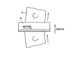
- FIG. 3 is a schematic plan view showing the meandering of the slab S in the rolling mill 30, and is a view of the plate surface of the slab S from the upper work roll 31 side.
- the slab S rolled by the upper work roll 31 and the lower work roll 32 does not travel parallel to the rolling direction but meanders.
- Such meandering occurs when one side and the other side are asymmetrically rolled in the width direction of the upper work roll 31 and the lower work roll 32.
- the one side and the other side of the rolling mill may mean a driving side driven by a motor of the rolling mill as described below and a working side opposite to the driving side.
- FIG. 4 shows an example of a cross-sectional view in which a slab that causes meandering is viewed in a cross section in the longitudinal direction (conveying direction).
- the plate thickness t 1 at one end is thicker than the plate thickness t 2 at the other end, and the plate thickness gradually changes from one to the other in the width direction.
- the thick part of the plate is stretched more than the thin part. The rolling reduction is larger at the end on the plate thickness t 1 side than on the plate thickness t 2 side on the entrance side.
- the material velocity on the inlet side is smaller at the end portion on the sheet thickness t 1 side than on the sheet thickness t 2 side, and the difference in the inlet side velocity between one end and the other end of the slab S, that is, the slab S
- the meandering occurs due to the rotation in the plane of.
- the value obtained by multiplying the speed of the slab S and the plate thickness is the inlet and outlet sides of the rolling mill. Will be the same.
- the delivery side plate thickness is uniform in the width direction
- a difference in plate thickness between the one end and the other end of the slab S on the rolling mill entrance side a difference in reduction occurs, and for example, the entrance side plate thickness is large.
- the end part has a lower entry side speed than the end part having a smaller entry side plate thickness. As a result, the end portion having a high entry side speed is drawn into the work roll faster than the end portion having a low entry side speed and rolled, the slab S is rotated at a rotational speed, and meandering occurs in the rolling mill.
- FIG. 5 is a plan view of the continuous casting apparatus 100 seen from directly above in the casting direction of the continuous casting apparatus 100.
- FIG. 5 is a diagram showing a state of the continuous casting device 100 when a wedge is generated in the cast slab S.
- FIG. 5 when the cast slab S is cast in a state where the rotation axes Ar1 and Ar2 of the first casting drum 111 and the second casting drum 112 are not parallel to each other, as shown in FIG.
- the plate thickness of S changes in the width direction to generate a wedge.
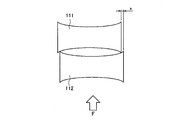
- 6 to 8 are views schematically showing the casting drum in the casting direction of the casting drum when adjusting the zero point of the rolling reduction position before the start of casting as seen from directly above the casting drum.
- the plate profile of the casting drum before the start of casting has a concave shape in the plate width direction. 6 to 8, the concave shape of the profile is emphasized for the sake of explanation. This is due to the fact that the first casting drum 111 and the second casting drum 112 undergo thermal expansion and change with the lapse of time from the start of casting to the arrival at steady casting.
- the initial profile of the casting drum is set so that the sheet profile (crown) of the metal ribbon during steady casting in which thermal expansion is observed becomes a desired sheet profile.
- the drum diameter at the center of the width of the casting drum is set to be a concave crown smaller than the drum diameters at both ends of the casting drum.
- the rolling position zero point adjustment is performed by bringing the pair of casting drums into contact (kissing) with each other and setting the rolling position (pressing position) when the predetermined load F is applied to zero. Done.
- the initial value of the rolling position of the cylinder for rolling the casting drum can be set.
- the casting drum has a concave crown as described above. Therefore, when the casting drums are brought into contact (kiss) with each other and a predetermined load F is applied to the casting drums, only both end portions of the casting drums come into contact with each other. Therefore, for example, as shown in FIG. 6, when the positions in the width direction of the casting drum do not completely match, when the predetermined load F is applied to the casting drum, the first casting drum 111 The contact points between the both end portions and the both end portions of the second casting drum 112 deviate from each other, and a deviation amount x occurs, resulting in an unstable state. Therefore, the precision of the rolling position zero point adjustment decreases.
- the rolling plate zero point adjustment is performed with a thin plate 118 sandwiched between the casting drums.
- the midpoint 118C of the width of the thin plate 118 is arranged on the straight line connecting the midpoints 111C and 112C of the widths of the first and second casting drums 111 and 112.
- the figure shows an example in which no deviation occurs at both ends of the casting drum. If no deviation occurs, the rotation axis Ar1 and the rotation axis Ar2 of the first casting drum 111 and the second casting drum 112 are parallel to each other, so that the rolling position zero point adjustment can be stably performed.
- the midpoint 118C of the width in the width direction of the thin plate 118 is the first casting drum 111 and the first casting drum 111.
- the thin plate 118 may not be arranged on the straight line connecting the intermediate points 111C and 112C of the length of the casting drum 112 in the width direction, but the thin plate 118 may be arranged near one end of the casting drum 112 in the width direction. is there.
- the rotating shaft Ar1 and the rotating shaft Ar2 of the first casting drum 111 and the second casting drum 112 are not parallel to each other, the left and right (the first casting drum 111 and the second casting drum 112 of the first casting drum 111 and the second casting drum 112 are adjusted even if the reduction position zero point adjustment is performed. Both ends in the width direction are in error. If casting is performed in such a state, wedges will be generated in the cast slab to be cast when controlled at the cylinder roll-down position.
- the inventors of the present invention reduce the wedge as described above by changing the plate thickness of the slab cast by the casting drum at both ends in the width direction of the slab.
- the method of controlling the plate thickness of the cast slab to be cast based on the estimated plate thickness was investigated.
- the estimation of the plate thickness will be explained.
- a plate thickness when a plate thickness is not installed, when determining the plate thickness, the contribution of each work roll deformation and the contribution of deformation other than the work roll are calculated.
- the thickness may be estimated by separating into. Specifically, in the rolling mill, the width direction length of the work roll is longer than the plate width of the slab, the gap between the width direction both ends of the work roll of the rolling mill is estimated, and the average of the gaps at both ends is used. The thickness of the center of the roll barrel is calculated.
- the rolling position zero point adjustment can be performed without error.Thus, by using the gaps at both ends, the plate thickness at the center of the slab can be accurately measured. Can be estimated.
- the rolling mill it is not possible to understand where the slab sent out from the continuous casting device is located in the width direction of the rolling mill. Therefore, even if it is possible to estimate the gap between the work rolls in the rolling mill, it is not possible to grasp at which position the gap corresponding to both ends of the slab is, it is possible to determine the plate thickness of both ends of the slab. Cannot be estimated. Therefore, the rolling mill could not estimate the wedges at both ends of the slab using the estimated plate thickness.
- the casting drum as shown in FIG. 5, a cast piece is cast by being surrounded by the first casting drum 111 and the second casting drum 112, and the side dams 150 provided at both ends in the width direction of the casting drum. It Therefore, the width direction length (barrel length) of the slab and the casting drum match.
- the inventors focused on this phenomenon, applied sheet thickness estimation in a rolling mill to a casting drum, estimated sheet thickness at both ends of a slab, and based on the estimated sheet thickness, It has been conceived that the wedge can be reduced by controlling the pressing means.
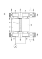
- FIG. 9 is a plan view showing an example of detailed configuration of the continuous casting apparatus as seen from directly above in the casting direction.
- the first casting drum 111 and the second casting drum 112 are arranged so as to face each other in the horizontal direction, and a slab is cast between the first casting drum 111 and the second casting drum 112.
- the first casting drum 111 and the second casting drum 112 are rotated by the drive of the motor M, and send the slab S downstream in the casting direction.
- the drive side by the motor M is the drive side DS
- the side opposite to the drive side is the work side WS.
- the side weirs 150d and the side weirs 150d are provided at both ends of the first casting drum 111 and the second casting drum 112 in the width direction so as to surround a gap formed by the first casting drum 111 and the second casting drum 112 facing each other.
- a side weir 150w is provided.
- the molten metal is stored in a region surrounded by the first casting drum 111 and the second casting drum 112, and the side weir 150d and the side weir 150w, and the cast slab S is sequentially cast.
- Both ends of the width direction axis of the first casting drum 111 and the second casting drum 112 are supported by the housing 130d and the housing 130w, respectively. Both ends of the axis of the second casting drum 112 in the width direction are connected to the cylinders 120d and 120w on the side opposite to the side on which the first casting drum 111 is arranged in the direction in which the casting drums face each other.
- the cylinder 120d and the cylinder 120w are movable in the directions in which the casting drums face each other.
- the second casting drum 112 is pressed down by the cylinders 120d and 120w so that both ends of the second casting drum 112 are arranged in the direction in which the casting drums are opposed to the side on which the first casting drum 111 is arranged.
- the cylinder 120d and the cylinder 120w can respectively independently control the both ends of the second casting drum 112.
- load cells 140d and 140w for measuring the load applied to the first casting drum 111 are provided on the opposite side to the side where the cylinders 120d and 120w are arranged. Thereby, the loads due to the reduction of the cylinder 120d and the cylinder 120w can be measured.
- sheet thickness estimation of the end portion Sd of the slab will be described as an example.
- the plate thickness is estimated from the drum gap of the casting drum.
- the drum gap of the casting drum changes due to the load applied to the casting drum, contact with the cast slab, and the like, in addition to the change due to the cylinder rolling position.
- the change in the drum gap due to the load applied to the casting drum and the contact with the cast slab is due to the contribution of elastic deformation of the casting drum, the contribution of elastic deformation other than the drum, and the contribution of change of the drum profile of the casting drum. , Can be considered separately.
- the elastic deformation contribution other than the casting drum is referred to as casting drum housing rolling system deformation. Based on these elastic deformation amounts and the rolling position of the cylinder, the estimated plate thickness of the end portion Sd can be estimated by the following formula 1.
- the cylinder roll-down position and the casting drum housing roll-down system deformation represent the differences from the time of adjusting the roll-down position zero point.
- the difference may be a deviation with respect to the cylinder rolling position at the time of adjusting the rolling position zero point and the deformation of the casting drum housing.
- the rolling position of the cylinder indicates the position of the cylinder in the direction in which the cylinder 120d of the continuous casting apparatus 100 moves.
- the rolling position of the cylinder refers to a position based on a difference from an initial value, which is a zero point where the position of the cylinder is zero-adjusted.
- the rolling position of the cylinder can be obtained from the displacement in the direction along the arrow a in FIG.
- the rolling position of the cylinder can be timely measured by a position sensor or the like (not shown) capable of measuring the movement amount of the cylinder 120d (or the cylinder 120w).
- the elastic deformation of the casting drum during casting refers to the elastic deformation of the casting drum at any time from the start of casting to the end of casting.
- the shaft of the casting drum bends or the casting drum undergoes flat deformation due to the reaction force from a slab that comes into contact with the casting drum or an external force applied to the casting drum.
- These deformations are called elastic deformations of the casting drum during casting.
- the elastic deformation of the casting drum can be obtained by means such as analysis using the theory of elasticity.
- the bending of the shaft of the casting drum which contributes to the deformation of the casting drum, can be calculated from the deflection of the beam in material mechanics by regarding the casting drum as a support beam at both ends.
- the load distribution in the width direction used when calculating the deflection there is no problem assuming a linear distribution in the width direction based on load cell values provided at both ends of the shaft of the casting drum.
- the casting drum housing rolling-down system deformation characteristic is a characteristic that the housing 130d and the housing 130w are deformed under the influence of the rolling load applied to the casting drum, and a characteristic that the structure for rolling down the casting drum including the cylinders 120d and 120w is deformed. Deformation characteristics including and are shown.
- the method described in Patent Document 5 can be used to determine the deformation characteristics of the casting drum housing rolling system.
- the deformation of the casting drum housing rolling system can be calculated based on the load measured by the load cell 140d (or the load cell 140w), as will be described later.
- the drum profile of the casting drum is an index indicating the amount of thermal expansion of the casting drum or the amount of wear of the casting drum.
- the amount of thermal expansion calculates the amount of deformation of the casting drum surface shape in consideration of the heat applied to the casting drum.
- the wear amount may be measured by actually measuring the drum profile before casting, or may be estimated from casting conditions. For example, since the surface shape at the time of designing the casting drum is known, the deformation amount of the drum profile can be obtained by adding the shape deformation due to thermal expansion and wear to the surface shape.
- the elastic deformation of the casting drum at the time of adjusting the rolling position zero point refers to the elastic deformation of the casting drum at the time of adjusting the rolling position zero point, which determines the initial value of the rolling position of the casting drum before the start of casting.
- the rolling position zero point adjustment is performed while a load is applied to the casting drum, so that elastic deformation occurs in the casting drum.
- the amount of elastic deformation at that time is the elastic deformation of the casting drum when the zero point of the rolling position is adjusted.
- This elastic deformation amount can be calculated from the deflection calculation of the beam of material mechanics in which the drum is regarded as a support beam at both ends, similarly to the elastic deformation of the casting drum during casting.
- the estimated plate thickness is calculated from the sum of the values of "cylinder reduction position”, “casting drum elastic deformation”, “casting drum housing reduction system deformation”, and “casting drum drum profile”. It is calculated by subtracting the value of "elastic deformation of the casting drum when adjusting the zero point of the rolling position of the drum”.
- the casting drum housing rolling-down system deformation characteristics showing the deformation characteristics of the constitutions other than the drum greatly depend on the delicate shape of the contact surface, especially in the low load region, and the characteristics change.
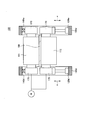
- FIG. 10 is a diagram showing an example of a method of acquiring the rolling drum deformation characteristic of the casting drum housing.
- the deformation characteristics of the casting drum housing rolling system are obtained by sandwiching the test plate 160 between the first casting drum 111 and the second casting drum 112.
- the test plate 160 has a length in the longitudinal direction longer than the barrel length in the width direction of the casting drum, and has a uniform plate thickness. From this state, the test plate 160 is pressed by the first casting drum 111 and the second casting drum 112 by pressing and tightening by the cylinder 120d and the cylinder 120w.
- the length of the test plate 160 in the direction perpendicular to the longitudinal direction is not limited, but the first casting drum 111 and the second casting drum 111 may be sufficiently contacted with the first casting drum 111 and the second casting drum 112. It is more preferable that the length is about 50 to 100 cm, which is about twice the drum diameter of 112.
- the deformation characteristic of the casting drum housing rolling system indicates the relationship between the load change and the amount of deformation of the casting drum housing rolling system. As a result, the effect of the amount of deformation of the rolling system including the casting drum housing and the cylinder depending on the load applied to the casting drum during casting can be accurately reflected in the estimated plate thickness.
- the test plate 160 is sandwiched between the casting drum and the casting plate while the first casting drum 111 and the second casting drum 112 are not rotated.
- the casting drum is tightened with a predetermined load larger than the load at the time of zero adjustment with respect to the test plate 160, and the rolling position of the casting drum and the load measured by the load cells 140d and 140w are acquired, and the load at each load is measured. Calculate the amount of deformation of the casting drum. Then, the deformation amount of the casting drum is subtracted from the pressing position of the casting drum to obtain the deformation amount of the casting drum housing pressing system for each load. This makes it possible to acquire the amount of deformation of the casting drum housing rolling-down system according to the load applied to the slab S when casting the slab S.
- the first casting drum 111 and the second casting drum 112 are rotated while the test plate 160 is sandwiched, and the casting drum is tightened with the above predetermined load for a predetermined time.
- the load is held and the average value of the load and the rolling position of the casting drum is acquired.
- the load of the casting drum is further changed, the changed load is held for a predetermined time, and the average value of another level of load and the rolling position of the casting drum is acquired.
- the time for holding each load may be two rotations of the casting drum.
- this average value may be calculated from time averages of time series data of the load and the rolling position obtained. In this way, the amount of deformation of the casting drum under each load is calculated, and the amount of deformation of the casting drum is subtracted from the rolling position of the casting drum, so that the amount of deformation of the casting drum housing rolling system for each load is acquired.
- the test plate 160 is formed of, for example, a material softer than the first casting drum 111 and the second casting drum 112 so as not to crush the dimples and the like formed on the surfaces of the first casting drum 111 and the second casting drum 112. More preferably. Although not limited, the test plate 160 is more preferably formed of, for example, an aluminum alloy.
- the acquisition of the deformation characteristics of the casting drum housing rolling system should be performed once before the start of a series of casting operations. Further, by performing it when a part of the configuration of the housing or the rolling reduction system is exchanged, it is possible to obtain the deformation characteristics of the rolling reduction system of the casting drum housing according to the equipment condition.
- the pair of side dams provided at the end portions in the width direction of the casting drum are opened so that the plate thickness between the casting drums is longer than the drum length of the casting drum.
- the uniform drum may be sandwiched and the casting drum may be tightened.
- the slab drum is tightened in a state where the rotating shafts of the casting drum are held in parallel, so that an even load can be applied to both ends of the casting drum, and the precision of the rolling position zero point adjustment is improved. be able to.
- the rolling position zero point adjustment can be performed without including an error due to the inclination of the rotation axis, so that the rolling position of the cylinder can be accurately controlled.
- the pair of side dams 150d and 150w provided at the widthwise end portions of the first casting drum 111 and the second casting drum 112 are opened to open the first casting drum 111 and the first casting drum 111.
- a plate having a length equal to and longer than the drum length of the casting drum is sandwiched between the second casting drum 112 and the casting drum 112, and the casting drum is tightened.
- the casting drum housing rolling-down system deformation characteristic indicating the deformation characteristic of the housing that supports the casting drum and the deformation characteristic of the rolling-down system that rolls down the casting drum is acquired. Note that the rolling position zero point adjustment may be performed together with the acquisition of the casting drum housing rolling system deformation characteristics.
- a control unit (not shown) that controls the continuous casting apparatus 100 calculates the plate thicknesses at both end portions of the slab in the width direction based on the above equation 1.
- the continuous casting apparatus 100 is provided with various measuring instruments such as a temperature measuring instrument for the first casting drum 111 and the second casting drum 112, a load cell 140d for measuring a load, and a load cell 140w.
- the control unit obtains various values from these various measuring instruments and calculates the estimated plate thickness at both ends of the cast piece by the above formula 1. Since the control unit can use the previously obtained casting drum housing rolling-down system deformation characteristic in the above equation 1, the estimated plate thickness can be calculated more accurately.
- the control unit controls the rolling positions of the cylinders provided at both end portions of the casting drum in the width direction so that the calculated difference in plate thickness between both end portions of the cast piece is equal to or less than a predetermined value.
- the wedge of the cast slab to be cast is reduced, and as a result, meandering in the rolling mill 30 arranged downstream of the continuous casting apparatus 100 can be prevented.
- the predetermined value of the calculated difference in plate thickness between both ends of the cast slab may be empirically obtained from, for example, the amount of meandering allowed in actual operation.
- the predetermined value may be 40 ⁇ m, and more specifically, 20 ⁇ m.
- a cast piece was cast and rolled using the continuous casting facility 1 shown in the above embodiment.
- the casting drum used in this example had a drum barrel length of 1000 mm.
- the values in the steady part were used.
- the evaluation of the wedge reduction effect is summarized in Table 1 below, and the absolute value of the wedge is described as ⁇ (good), less than 40 ⁇ m as ⁇ (pass), and above as x (fail).
- Example 1 As shown in FIG. 10, a pair of side dams provided at the widthwise end portions of the casting drum are opened so that the length between the casting drums is longer than the drum length of the casting drum and the plate thickness is uniform.
- the zero point of the rolling position was adjusted with the blank plate sandwiched.
- this rolling position zero point adjusting method is indicated as A.
- the pressing position of the cylinders provided at both ends of the casting drum was controlled so that the estimated plate thicknesses at both ends of the cast slab were the same on the left and right in the width direction.
- Example 2 as a method for adjusting the rolling position zero point, a plate having a length shorter than the drum barrel length of the casting drum as shown in FIG. 7 was sandwiched between a pair of casting drums to perform the rolling position zero point adjustment.
- this rolling position zero point adjusting method is described as B.
- the pressing position of the cylinders provided at both ends of the casting drum was controlled so that the estimated plate thicknesses at both ends of the cast slab were the same on the left and right in the width direction.
- Comparative Example 1 As in the case of Example 2, a plate having a length shorter than the drum barrel length of the casting drum as shown in FIG. 7 was sandwiched between a pair of casting drums and the rolling position zero adjustment was performed. During casting of the cast slab, the estimated plate thickness was not used, and the rolling positions of the cylinders provided at both ends of the casting drum were controlled so that the rolling forces at both ends of the casting drum were the same on the left and right.
- Comparative Example 2 as in the case of Example 2, a plate having a length shorter than the drum barrel length of the casting drum as shown in FIG. 7 was sandwiched between a pair of casting drums to adjust the rolling position zero point. During the casting of the cast slab, the rolled position of the cylinders provided at both ends of the cast drum was controlled so that the rolled positions at both ends of the cast drum were the same on both sides without using the estimated plate thickness.
- the plate thicknesses measured at the steady part were 1.820 mm at the end of the drive side DS and 1.830 mm at the end of the work side WS.
- the wedge (wedge amount) was -10 ⁇ m, which was very good. Further, in the rolling process in the rolling mill installed downstream of the continuous casting apparatus, meandering did not occur, and rolling could be performed without any problem.
- the plate thicknesses measured at the steady part were 1.795 mm at the end of the drive side DS and 1.828 mm at the end of the work side WS. Therefore, the wedge was -33 ⁇ m, which was good. Further, in the rolling process in the rolling mill installed downstream of the continuous casting apparatus, meandering did not occur, and rolling could be performed without any problem.
- the plate thickness measured in the steady part was 1.800 mm at the end of the drive side DS and 1.720 mm at the end of the work side WS.
- the wedge was as large as 80 ⁇ m, and meandering occurred in the rolling process in the rolling mill installed downstream of the continuous casting apparatus, and the slab was broken.
- the actual measured plate thickness in the steady part was 1.870 mm at the end of the drive side DS and 1.750 mm at the end of the work side WS.
- the wedge was as large as 120 ⁇ m, and meandering occurred in the rolling process in the rolling mill installed downstream of the continuous casting device, and the slab was broken.
- the twin-drum type continuous casting apparatus casting showing the deformation characteristics of the housing supporting the casting drum and the deformation characteristics of the reduction system for rolling down the casting drum, which are obtained before the start of casting the cast piece.
- the estimated plate thickness is calculated from Equation 1 above, and the rolling position of the cylinder is controlled so that the difference between both ends of the cast piece is below a predetermined value.
- the wedge of the slab can be reduced well, and meandering can be prevented in the rolling mill installed downstream of the casting drum.
- the present invention has a high industrial applicability because it can provide a casting method of a slab that can reduce wedges more accurately.
Landscapes
- Engineering & Computer Science (AREA)
- Mechanical Engineering (AREA)
- Continuous Casting (AREA)
Abstract
Priority Applications (5)
| Application Number | Priority Date | Filing Date | Title |
|---|---|---|---|
| CN201980067426.XA CN112839754B (zh) | 2018-10-22 | 2019-10-21 | 铸板的铸造方法 |
| KR1020217010872A KR102480616B1 (ko) | 2018-10-22 | 2019-10-21 | 주편의 주조 방법 |
| US17/283,131 US12097554B2 (en) | 2018-10-22 | 2019-10-21 | Slab casting method |
| JP2020553400A JP7127695B2 (ja) | 2018-10-22 | 2019-10-21 | 鋳片の鋳造方法 |
| BR112021005013-2A BR112021005013B1 (pt) | 2018-10-22 | 2019-10-21 | Método de lingotamento de placa |
Applications Claiming Priority (2)
| Application Number | Priority Date | Filing Date | Title |
|---|---|---|---|
| JP2018198355 | 2018-10-22 | ||
| JP2018-198355 | 2018-10-22 |
Publications (1)
| Publication Number | Publication Date |
|---|---|
| WO2020085313A1 true WO2020085313A1 (fr) | 2020-04-30 |
Family
ID=70332120
Family Applications (1)
| Application Number | Title | Priority Date | Filing Date |
|---|---|---|---|
| PCT/JP2019/041336 Ceased WO2020085313A1 (fr) | 2018-10-22 | 2019-10-21 | Procédé de fabrication de brame |
Country Status (6)
| Country | Link |
|---|---|
| US (1) | US12097554B2 (fr) |
| JP (1) | JP7127695B2 (fr) |
| KR (1) | KR102480616B1 (fr) |
| CN (1) | CN112839754B (fr) |
| TW (1) | TW202023709A (fr) |
| WO (1) | WO2020085313A1 (fr) |
Families Citing this family (1)
| Publication number | Priority date | Publication date | Assignee | Title |
|---|---|---|---|---|
| TW202019582A (zh) * | 2018-10-22 | 2020-06-01 | 日商日本製鐵股份有限公司 | 鑄片的製造方法及控制裝置 |
Citations (8)
| Publication number | Priority date | Publication date | Assignee | Title |
|---|---|---|---|---|
| JPS6083747A (ja) * | 1983-10-12 | 1985-05-13 | Ishikawajima Harima Heavy Ind Co Ltd | 回転鋳造装置 |
| JPS6083746A (ja) * | 1983-10-12 | 1985-05-13 | Ishikawajima Harima Heavy Ind Co Ltd | 回転鋳造装置 |
| JPH01317660A (ja) * | 1988-06-20 | 1989-12-22 | Hitachi Ltd | 双ロール式連鋳機 |
| JPH04187345A (ja) * | 1990-11-22 | 1992-07-06 | Mitsubishi Heavy Ind Ltd | 連鋳機の板厚検出方法および装置 |
| JPH06106305A (ja) * | 1992-09-28 | 1994-04-19 | Hitachi Zosen Corp | ツインモールドロール型薄板連続鋳造設備の鋳片厚さ制御装置 |
| JPH08229639A (ja) * | 1994-10-28 | 1996-09-10 | Usinor Sacilor Sa | 2本のロール間で薄い金属製品を成形する方法および装置 |
| JP2008213014A (ja) * | 2007-03-07 | 2008-09-18 | Ihi Corp | ストリップ形状厚さ制御方法 |
| JP2017196636A (ja) * | 2016-04-26 | 2017-11-02 | 新日鐵住金株式会社 | 双ドラム式連続鋳造装置、及び、金属薄帯の製造方法 |
Family Cites Families (10)
| Publication number | Priority date | Publication date | Assignee | Title |
|---|---|---|---|---|
| JPS58173837A (ja) | 1982-04-05 | 1983-10-12 | Sanyo Electric Co Ltd | 熱酸化膜の形成方法 |
| JPS6030508A (ja) | 1983-07-28 | 1985-02-16 | Nippon Steel Corp | 圧延機の圧下設定制御方法 |
| JPH0622122B2 (ja) | 1985-11-25 | 1994-03-23 | 三井金属鉱業株式会社 | 亜鉛アルカリ電池 |
| FR2610227B1 (fr) * | 1987-02-04 | 1990-04-20 | Siderurgie Fse Inst Rech | Systeme de maintien de la tete d'ancrage d'un mannequin d'extraction dans une installation de coulee continue entre cylindres |
| JPH01166863A (ja) | 1987-12-23 | 1989-06-30 | Nippon Steel Corp | 双ドラム式連鋳機の圧下制御方法及び装置 |
| FR2699438A1 (fr) * | 1992-12-22 | 1994-06-24 | Usinor Sacilor | Jauge et procédé de calibrage d'une cage de formage d'un produit métallique et leur utilisation. |
| KR100290639B1 (ko) * | 1996-12-24 | 2001-06-01 | 이구택 | 쌍롤식 박판제조장치의 롤 갭 제어방법 |
| JPH10305352A (ja) * | 1997-05-07 | 1998-11-17 | Sumitomo Metal Ind Ltd | 双ロール式連続鋳造機の制御方法 |
| JP2002219558A (ja) * | 2001-01-24 | 2002-08-06 | Mitsubishi Heavy Ind Ltd | 双ドラム式連続鋳造装置 |
| BRPI0621612A2 (pt) * | 2006-04-26 | 2011-12-13 | Ihi Corp | fundidor de rolo duplo |
-
2019
- 2019-10-18 TW TW108137759A patent/TW202023709A/zh unknown
- 2019-10-21 US US17/283,131 patent/US12097554B2/en active Active
- 2019-10-21 KR KR1020217010872A patent/KR102480616B1/ko active Active
- 2019-10-21 WO PCT/JP2019/041336 patent/WO2020085313A1/fr not_active Ceased
- 2019-10-21 CN CN201980067426.XA patent/CN112839754B/zh active Active
- 2019-10-21 JP JP2020553400A patent/JP7127695B2/ja active Active
Patent Citations (8)
| Publication number | Priority date | Publication date | Assignee | Title |
|---|---|---|---|---|
| JPS6083747A (ja) * | 1983-10-12 | 1985-05-13 | Ishikawajima Harima Heavy Ind Co Ltd | 回転鋳造装置 |
| JPS6083746A (ja) * | 1983-10-12 | 1985-05-13 | Ishikawajima Harima Heavy Ind Co Ltd | 回転鋳造装置 |
| JPH01317660A (ja) * | 1988-06-20 | 1989-12-22 | Hitachi Ltd | 双ロール式連鋳機 |
| JPH04187345A (ja) * | 1990-11-22 | 1992-07-06 | Mitsubishi Heavy Ind Ltd | 連鋳機の板厚検出方法および装置 |
| JPH06106305A (ja) * | 1992-09-28 | 1994-04-19 | Hitachi Zosen Corp | ツインモールドロール型薄板連続鋳造設備の鋳片厚さ制御装置 |
| JPH08229639A (ja) * | 1994-10-28 | 1996-09-10 | Usinor Sacilor Sa | 2本のロール間で薄い金属製品を成形する方法および装置 |
| JP2008213014A (ja) * | 2007-03-07 | 2008-09-18 | Ihi Corp | ストリップ形状厚さ制御方法 |
| JP2017196636A (ja) * | 2016-04-26 | 2017-11-02 | 新日鐵住金株式会社 | 双ドラム式連続鋳造装置、及び、金属薄帯の製造方法 |
Also Published As
| Publication number | Publication date |
|---|---|
| JP7127695B2 (ja) | 2022-08-30 |
| TW202023709A (zh) | 2020-07-01 |
| US20210387249A1 (en) | 2021-12-16 |
| KR102480616B1 (ko) | 2022-12-26 |
| BR112021005013A2 (pt) | 2021-06-08 |
| JPWO2020085313A1 (ja) | 2021-09-02 |
| KR20210058905A (ko) | 2021-05-24 |
| CN112839754A (zh) | 2021-05-25 |
| CN112839754B (zh) | 2023-01-03 |
| US12097554B2 (en) | 2024-09-24 |
Similar Documents
| Publication | Publication Date | Title |
|---|---|---|
| JP5976087B2 (ja) | 薄板製造装置における鋳造ロールの損傷防止装置 | |
| JP2009528920A (ja) | ストリップ平坦度及びストリッププロフィールの総合的な監視及び制御方法及びプラント | |
| JPH08229639A (ja) | 2本のロール間で薄い金属製品を成形する方法および装置 | |
| JP6569494B2 (ja) | 薄肉鋳片製造設備、及びピンチロールのレベリング方法 | |
| US11858019B2 (en) | Slab manufacturing method and control device | |
| JP7127695B2 (ja) | 鋳片の鋳造方法 | |
| CN100546739C (zh) | 薄带连铸带厚控制方法和装置 | |
| JP3016632B2 (ja) | 双ロール式連鋳機の運転制御法 | |
| JP2909763B2 (ja) | 双ロール式連鋳機のロール回転速度制御方法 | |
| JP4461075B2 (ja) | 連続鋳造方法 | |
| BR112021005013B1 (pt) | Método de lingotamento de placa | |
| JP2909762B2 (ja) | 双ロール式連鋳機の圧着負荷制御方法 | |
| BR112021006144B1 (pt) | Método de fabricação de placa e dispositivo de controle | |
| KR20250001172A (ko) | 주름 방지 롤의 위치 제어 시스템 및 방법 | |
| JP2024139201A (ja) | 板圧延用圧延機、圧延機のロール圧下位置の検出方法および制御方法ならびに圧延板の製造方法 | |
| KR100490994B1 (ko) | 쌍롤형 박판주조장치의 웨지제어를 통한 압하력 제어방법 | |
| JPH0338940B2 (fr) | ||
| JPS62156051A (ja) | 双ロ−ル式金属急冷薄帯の製造方法 | |
| JPH07108436B2 (ja) | 双ロール式連鋳機 | |
| JPH0359781B2 (fr) | ||
| JPH0667535B2 (ja) | 双ロ−ル式連続鋳造機による薄板連鋳方法 | |
| KR20040056094A (ko) | 쌍롤형 박판 주조장치에서 엑스레이 게이지를 이용한 박판두께 제어장치 및 방법 | |
| JPH02274354A (ja) | 鋼の連続鋳造方法 | |
| JPS6225458B2 (fr) | ||
| JPS62252641A (ja) | 金属薄板帯の直接製造方法および製造装置 |
Legal Events
| Date | Code | Title | Description |
|---|---|---|---|
| 121 | Ep: the epo has been informed by wipo that ep was designated in this application |
Ref document number: 19875241 Country of ref document: EP Kind code of ref document: A1 |
|
| ENP | Entry into the national phase |
Ref document number: 2020553400 Country of ref document: JP Kind code of ref document: A |
|
| REG | Reference to national code |
Ref country code: BR Ref legal event code: B01A Ref document number: 112021005013 Country of ref document: BR |
|
| ENP | Entry into the national phase |
Ref document number: 20217010872 Country of ref document: KR Kind code of ref document: A |
|
| NENP | Non-entry into the national phase |
Ref country code: DE |
|
| ENP | Entry into the national phase |
Ref document number: 112021005013 Country of ref document: BR Kind code of ref document: A2 Effective date: 20210317 |
|
| 122 | Ep: pct application non-entry in european phase |
Ref document number: 19875241 Country of ref document: EP Kind code of ref document: A1 |