WO2020090130A1 - 移動体洗浄マット - Google Patents
移動体洗浄マット Download PDFInfo
- Publication number
- WO2020090130A1 WO2020090130A1 PCT/JP2019/007650 JP2019007650W WO2020090130A1 WO 2020090130 A1 WO2020090130 A1 WO 2020090130A1 JP 2019007650 W JP2019007650 W JP 2019007650W WO 2020090130 A1 WO2020090130 A1 WO 2020090130A1
- Authority
- WO
- WIPO (PCT)
- Prior art keywords
- mat
- moving body
- shoe sole
- pump chamber
- cleaning
- Prior art date
- Legal status (The legal status is an assumption and is not a legal conclusion. Google has not performed a legal analysis and makes no representation as to the accuracy of the status listed.)
- Ceased
Links
Images










Classifications
-
- A—HUMAN NECESSITIES
- A47—FURNITURE; DOMESTIC ARTICLES OR APPLIANCES; COFFEE MILLS; SPICE MILLS; SUCTION CLEANERS IN GENERAL
- A47G—HOUSEHOLD OR TABLE EQUIPMENT
- A47G27/00—Floor fabrics; Fastenings therefor
- A47G27/02—Carpets; Stair runners; Bedside rugs; Foot mats
-
- A—HUMAN NECESSITIES
- A47—FURNITURE; DOMESTIC ARTICLES OR APPLIANCES; COFFEE MILLS; SPICE MILLS; SUCTION CLEANERS IN GENERAL
- A47L—DOMESTIC WASHING OR CLEANING; SUCTION CLEANERS IN GENERAL
- A47L23/00—Cleaning footwear
- A47L23/22—Devices or implements resting on the floor for removing mud, dirt, or dust from footwear
-
- B—PERFORMING OPERATIONS; TRANSPORTING
- B60—VEHICLES IN GENERAL
- B60S—SERVICING, CLEANING, REPAIRING, SUPPORTING, LIFTING, OR MANOEUVRING OF VEHICLES, NOT OTHERWISE PROVIDED FOR
- B60S3/00—Vehicle cleaning apparatus not integral with vehicles
- B60S3/04—Vehicle cleaning apparatus not integral with vehicles for exteriors of land vehicles
Definitions
- the present invention relates to a moving body cleaning mat which can wash a moving body with a simple structure by converting the energy of the moving body into the jetting energy of a fluid without requiring the supply of energy from other than the moving body.
- An example of a device for cleaning the adhering matter that has adhered to the moving body is a shoe sole cleaning device or a vehicle tire cleaning device.
- the shoe sole cleaning device is used to remove soil and sand adhering to the shoe sole, and is installed at the entrance of a building or room.
- the conventional shoe sole cleaning device cannot reliably remove soil and sand unless the pedestrian consciously rubs the shoe sole on the shoe sole cleaning device.
- a shoe sole cleaning device capable of removing soil and sand adhering to the shoe sole without intentionally rubbing the shoe sole cleaning device (for example, Patent Document 1).
- the shoe sole cleaning device described in Patent Document 1 has a box-shaped main body case, a rotary shaft housed inside the main body case, a brush portion provided on the outer periphery of the rotary shaft, and a rotary shaft for rotating the rotary shaft.
- Rotating shaft driving means a container body disposed below the rotating shaft for storing falling objects, a compressed air supply unit for supplying compressed air to the shaft hole of the rotating shaft, and a shoe sole. It is provided with a detecting means and a power supply section for supplying electric power to the rotating shaft drive means and the compressed air supply means.
- the rotating shaft is rotated by the rotating shaft driving means, and the brush portion is rubbed against the shoe sole, whereby dirt on the shoe sole is removed. Further, the compressed air supplied from the compressed air supply unit is blown onto the shoe sole through the shaft hole of the rotary shaft, whereby the dirt adhering to the shoe sole can be removed more reliably.
- the tire cleaning device described in Patent Document 2 includes an elastically deformable cylinder, a tread that can press the cylinder from above, a water supply port that is connected to one end of the cylinder and that supplies cleaning water, and a cylinder. It is provided with a water discharge port which is connected to the other end and discharges washing water.
- This water supply port is configured by piping and is configured toward the side surface of the vehicle tire. In this tire cleaning device, the cylinder is crushed by the pressing force from the tire, so that the cleaning water inside the cylinder is ejected from the water outlet to clean the tire.
- the shoe sole cleaning device described in the cited document 1 supplies electric power to the rotary shaft drive means and the compressed air supply means in addition to the compressed air supply unit for supplying the compressed air to the rotary shaft drive means and the shaft hole of the rotary shaft. Since a power supply unit is required, the configuration of the device becomes complicated and the assembly work and the transportation work are troublesome.
- the water discharge port and the water supply port are configured by pipes, and the pipe is provided such that the water discharge port faces the side surface of the tire and a plurality of pipes are provided in the traveling direction. Therefore, installation of the tire cleaning device is troublesome. Further, this tire cleaning device is a large-scale device and has a complicated structure, so that the cost is high. Furthermore, since the water discharge port is provided toward the side surface of the tire, it is not possible to properly remove the dirt attached to the running surface of the tire and the dirt buried in the groove formed on the running surface.
- an object of the present invention is to provide a moving body cleaning mat that can wash a moving body with a simple structure.
- the moving body cleaning mat according to the present invention can be used, for example, in a shoe bottom cleaning device for cleaning shoe soles of pedestrians or a tire cleaning device for cleaning vehicle tires.
- a moving body cleaning mat is for removing deposits adhering to a moving body, and includes a mat portion that receives a pressing force from the moving body and a plurality of fluid discharge / suction portions provided on a surface portion of the mat portion. And a plurality of pump chambers that are formed inside the mat portion and that store fluid to be discharged or sucked through the fluid discharge / suction portion.
- the moving body steps on the surface portion of the mat portion.
- the pump chamber is deformed by the pressing force, and the fluid is ejected to the moving body.
- the surface part of the mat part corresponding to the plurality of pump chamber parts is formed in a protruding shape.
- the bottom part of the pump chamber part is removable.
- the moving body cleaning mat according to the present disclosure has a protruding adhesion preventing portion on the surface of the mat portion to prevent the moving body from adhering to the opening of the fluid discharge / suction portion.
- the moving body cleaning mat according to the present disclosure has a simple structure, it can be easily transported and installed. Further, since the energy transmitted from the moving body to the mat portion is converted into the jetting energy of the fluid, the fluid can be jetted from the fluid discharge / suction unit to the moving body even when the energy is not supplied from other than the moving body. it can. Then, the impact of the fluid colliding with the moving body can remove the deposits on the moving body. For example, if a shoe-cleaning device or tire-cleaning device equipped with this moving body cleaning mat is installed at the entrance of a building or the entrance of a construction truck, the fluid ejected from the fluid discharge / suction unit will cause it to adhere to the soles and tires. The attached matter can be removed, and it is possible to prevent the attached floor or tire surface from being contaminated by the attached matter on the soles or tires.
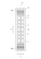
- FIG. 1 is a plan view of a shoe sole cleaning device including a moving body cleaning mat according to a first embodiment of the present disclosure.
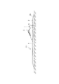
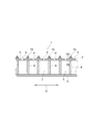
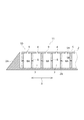
- 1 is a cross-sectional view of a shoe sole cleaning device including a moving body cleaning mat according to a first embodiment of the present disclosure. It is a figure which shows the use condition of the shoe sole washing
- FIG. 3 is a cross-sectional view for explaining a structure in which a bottom portion forming a pump chamber portion is detachable in the moving body washing mat (shoe bottom washing mat) according to the first embodiment of the present disclosure.
- FIG. 5 is a cross-sectional view showing an example in which a contact prevention portion is provided in the moving body cleaning mat according to the first embodiment of the present disclosure. It is sectional drawing which shows the other example of the contact prevention part provided in the moving body cleaning mat which concerns on 1st embodiment of this indication. It is a top view of a tire washing device provided with a mobile body washing mat (tire washing mat) concerning a second embodiment of this indication. It is a figure which shows the use condition of the tire washing
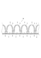
- FIG. 11 is a cross-sectional view showing an example in which a surface portion of a mat portion corresponding to a pump chamber portion of a moving body cleaning mat according to another embodiment of the present disclosure is formed in a protrusion shape.
- FIG. 11 is a cross-sectional view showing an example in which a surface portion of a mat portion corresponding to a pump chamber portion of a moving body cleaning mat according to another embodiment of the present disclosure is formed in a protrusion shape.
- FIG. 9 is a cross-sectional view showing an example in which the bottom of a moving body cleaning mat according to another embodiment of the present disclosure is fully opened.
- FIG. 11 is a cross-sectional view showing an example in which a surface portion of a mat portion corresponding to a pump chamber portion of a moving body cleaning mat according to another embodiment of the present disclosure is formed in a protrusion shape.
- FIG. 9 is a cross-sectional view showing an example in which the bottom of a moving body cleaning mat according to another embodiment of the present disclosure is fully
- FIG. 7 is a cross-sectional view showing an example in which a support member is provided on a side member of a moving body cleaning mat according to another embodiment of the present disclosure.
- FIG. 9 is a cross-sectional view illustrating a moving body cleaning mat according to another embodiment of the present disclosure, in which a bottom portion of the moving body cleaning mat is partially opened. It is sectional drawing which shows the modification of the side member of the moving body cleaning mat which concerns on other embodiment of this indication. It is sectional drawing which shows the modification of the side member of the moving body cleaning mat which concerns on other embodiment of this indication.
- the moving body cleaning mat according to this embodiment is one in which mechanical energy is directly transmitted from the moving body.
- the shoe sole cleaning mat will be described as an example in the first embodiment, and the tire cleaning mat will be described as an example in the second embodiment.
- the length direction of the shoe sole cleaning mat is defined as the longitudinal direction X and the width direction is defined as the lateral direction Y.
- the shoe sole cleaning mat 1 according to this embodiment is used to remove soil, sand, and dust (hereinafter referred to as adhered matter) adhering to the shoe sole by injecting a fluid onto the shoe sole. ..
- a shoe sole cleaning mat 1 according to this embodiment includes a mat (mat portion) 2 that receives a pressing force from the outside, and a plurality of pump chambers formed inside the mat 2.
- a (pump chamber) 3 and a discharge / suction hole 4 as a plurality of fluid discharge / suction parts provided in the mat 2 are provided.
- the mat 2 is housed in a frame member 2A having an inner peripheral wall corresponding to the outer shape of the mat 2, for example, and is used as a shoe sole cleaning device 11. As shown in FIG. 3, the shoe sole cleaning device 11 is installed so that a user walks on the shoe sole cleaning mat 1.
- the frame member 2 ⁇ / b> A is formed in a slope shape around the frame member 2 ⁇ / b> A and has a shape that does not trip when a pedestrian passes through the shoe sole cleaning device 11. Further, a protrusion or a slip stopper is formed on a portion of the frame member 2A that is in contact with the installation surface (for example, the floor surface), and the frame member 2A has a shape that is unlikely to slip on the installation surface.
- a member having a small elasticity can be used as the frame member 2A, and the frame member 2A plays a cushioning role between the installation surface and the shoe sole cleaning mat 1. Therefore, even if the shoe sole cleaning mat 1 expands or contracts, the frame member 2A is unlikely to shift with respect to the floor surface.
- the mat 2 connects the ceiling member 5 that forms the surface portion of the mat 2, the bottom member 6 that forms the bottom portion of the mat 2, and the ceiling member 5 and the bottom member 6, and forms the side wall of the pump chamber 3. And a plurality of side members (side portions) 8 (FIG. 2).
- the mat 2 has a rectangular shape, and the length of the mat 2 is designed to be longer than the stride of the user, for example.
- the mat 2 is made of an elastic material.
- the mat 2 is crushed when receiving a pressing force from the outside, and is restored to the original state when the pressing force from the outside is stopped. Since the mat 2 is repeatedly subjected to a pressing force from the outside, it is preferable to use a material having excellent restoring force and durability for this mat 2.
- an elastic member such as a rubber material can be used.
- the top member 5, the bottom member 6, and the side member 8 may be made of the same material or different materials. Further, a plurality of the mats 2 may be arranged vertically and horizontally and used.
- the bottom member 6 may be provided with a detachable portion 7 so that it can be detached from the side member 8.
- the attaching / detaching portion 7 the bottom member 6 can be easily removed, and the deposits and the like accumulated in the pump chamber 3 can be easily washed.
- the pump chamber 3 A plurality of pump chambers 3 are formed in each of the longitudinal direction X and the lateral direction Y.
- the pump chamber 3 has a top member 5 as an upper wall, a bottom member 6 as a lower wall, and side members 8 as side walls.
- the ceiling member 5 receives a pressing force from the outside, the ceiling member 5 is crushed and the side member 8 is deformed, so that the volume of the pump chamber 3 becomes smaller.
- the pump chamber 3 has various shapes such as a cube, a rectangular parallelepiped, a cylinder, and a cone. Further, the shape of the pump chamber 3 is determined in consideration of the difficulty of production, the efficiency of discharge and suction, and the like.
- the discharge / suction hole 4 is formed so as to penetrate the front surface 5A and the back surface 5B of the ceiling member 5, and the opening 9 of the discharge / suction hole 4 is formed in a circular shape.
- a plurality of the discharge suction holes 4 are provided at equal intervals in the longitudinal direction X and the lateral direction Y.
- the exhaust suction hole 4 plays a role as a flow path for air inside and outside the mat 2. Specifically, when the ceiling member 5 receives a pressing force from the outside, the fluid (air) inside the pump chamber 3 is discharged to the outside of the mat 2 via the discharge / suction hole 4.
- the discharge suction hole 4 may have various shapes such as an oval shape, a quadrangle shape, a star shape, a triangle shape, or a slit. In addition, it can be determined in consideration of the degree of difficulty of manufacturing, the efficiency of discharging and sucking air, and the like. The arrangement and number of the exhaust suction holes 4 are determined in consideration of the efficiency of exhaust suction of air.
- the ceiling member 5 of the mat 2 receives a pressing force from the shoe sole 15, and the side member 8 is crushed and deformed, so that the pump chamber 3 of the pump chamber 3 is deformed. The volume becomes smaller. Then, the air inside the pump chamber 3 is vigorously jetted from the exhaust suction hole 4 toward the shoe sole 15 (arrow F1). The injected air collides from below the shoe sole 15, and the impact of the collision removes deposits from the shoe sole 15. On the other hand, when the shoe sole 15 separates from the mat 2, the deformed pump chamber 3 is restored to its original state, so that the deposit is sucked into the pump chamber 3 (arrow F2).
- the adhering matter adhering to the shoe sole 15 can be removed by jetting (arrow F1) and suction (arrow F2). Further, since air is ejected from the pump chamber 3 stepped on the shoe sole 15, fluid is ejected from below the shoe sole 15, and air can be ejected to the groove portion of the shoe sole 15 as well. It is also possible to remove deposits attached to the.
- the pump chamber 3 corresponding to the place where the shoe sole 15 is stepped is deformed, but the other pump chambers 3 are not deformed. Therefore, the pressing force of the shoe sole 15 can be efficiently converted into the injection energy. As a result, the fluid is strongly jetted to the sole 15 (arrow F1).
- the top members 5 on the left and right sides of the surface in contact with the sole 15 also bends. Therefore, not only the volume of the pump chamber 3 corresponding to the surface directly receiving the pressing force from the shoe sole 15 but also the volume of the pump chamber 3 around it becomes small. Then, air is also jetted from around the shoe sole 15, and in addition to the shoe sole 15, the deposits around the shoe sole 15 are removed.
- the pump chamber 3 stepped on the shoe sole 15 efficiently receives a pressing force from the shoe sole 15 and the internal pressure of the pump chamber 3 is increased.
- the opening 9 of the discharge suction hole 4 faces toward the shoe sole 15 due to the nature of the mat, so that the air is absorbed by the shoe. It is jetted toward.
- a plurality of pump chambers 3 are provided and partitioned by the side member 8. Therefore, when the ceiling member 5 is pressed, air is internally circulated between the pump chambers 3. Or do not move. Therefore, air can be efficiently discharged or sucked through the discharge / suction hole 4.
- the shoe sole cleaning device 11 includes the shoe sole cleaning mat 1 inside the frame member 2A (FIG. 2), and these frame member 2A and shoe sole cleaning mat 1 are It can be manufactured integrally.
- the frame member 2A and the shoe sole cleaning mat 1 are integrally manufactured, the structure is simplified and the cost can be reduced.
- the arrangement or shape of the pump chamber 3 and the arrangement or shape of the discharge / suction hole 4 are determined by the type of fluid, the ejection efficiency of the fluid, the size of the moving body cleaning mat, the difficulty of production, the cost, and the like.
- the shoe sole cleaning device 11 that uses air as the fluid has been described, but the shoe sole cleaning device 11 may be applied to, for example, a device that is installed at the entrance of a food factory and sterilizes the shoe sole 15. You can also In this case, the shoe sole cleaning mat 1 is used by immersing it in a liquid antiseptic solution. Since the shoe sole cleaning device 11 can wash the shoe sole 15 by stepping on the shoe sole cleaning mat 1 many times, the shoe sole cleaning device 11 can be downsized and used. .. Further, by providing the shoe bottom cleaning device 11 in which air is jetted adjacent to the shoe sole washing device 11 using the disinfectant solution, the air jetted from the pump chamber 3 blows off the antiseptic solution to the shoe sole 15. It is possible to prevent the attached extra disinfectant solution from spreading to the surroundings.
- the top surface 5A of the top member 5 of the shoe sole cleaning mat 1 may be provided with a protrusion 16 as a shoe sole contact preventing member, as shown in FIG.
- the protrusion 16 has a conical shape and is provided between the discharge suction holes 4 adjacent to each other in the longitudinal direction X.
- the shape of the protrusion 16 is not limited to a conical shape, and for example, a rectangular parallelepiped shape can be used as shown in FIG. 7.
- a brush 17 may be provided on the front surface 5A of the ceiling member 5.
- the brush 17 plays a role of a shoe sole contact prevention member and also a role of scraping off an adhered matter fitted in a groove formed in the shoe sole 15.
- the adhesion preventing member is determined in consideration of the shape, arrangement, size, material, design, etc. of which the shoe sole 15 is unlikely to slip.
- the shoe sole cleaning device 11 provided with this shoe sole cleaning mat has an assembly work as compared with a shoe sole cleaning device using a motor or a power source. In addition to easy installation work, there is no burden on transportation work.
- the tire cleaning mat 21 as the moving body cleaning mat according to the present embodiment is used for ejecting a fluid to a tire of a vehicle to remove a deposit on the tire. Since the tire cleaning mat 21 has substantially the same basic structure, the same components are designated by the same reference numerals, and detailed description thereof will be omitted.
- the tire cleaning device 22 has a water tank 24 filled with water on the iron plate 23, and an inclination provided before and after the longitudinal direction X of the water tank 24.
- the members 24A and 24B are arranged, and the tire washing mat 21 is provided in the water tank 24.
- the inclined members 24A and 24B are slopes on which the vehicle rides on the water tank 24.
- the length of the tire cleaning mat 21 is designed to be equal to or longer than the outer circumference of the tire 25. Further, the tire cleaning mat 21 can be divided into a plurality of pieces and arranged side by side.
- the tire cleaning device 22 is installed at the entrance / exit of the construction truck.
- the arrangement or shape of the pump chamber 3 and the arrangement or shape of the discharge / suction hole 4 are determined depending on the type of fluid, the ejection efficiency of the fluid, the size of the moving body cleaning mat, the difficulty of production, the cost, and the like. Further, a rubber material or the like having an elastic force can be used as a member forming the mat 2.
- a moving body cleaning mat having the following configuration may be used.
- the ceiling member 5 of the mat 2 corresponding to the plurality of pump chambers 3 is formed in a protruding shape.
- the side member 8 is not provided.
- the moving body cleaning mat 1A can be manufactured at low cost because the pump chamber 3 is composed of the protruding top member 5 and the bottom member 6 and has a simple structure. By providing a reinforcing member inside the pump chamber 3 or changing the thickness of the ceiling member 5, the ceiling member 5 can be easily restored to its original state.
- the moving body cleaning mat 1B is formed by connecting the mat 2 of the moving body cleaning mat 1A to the bottom member 6 via the side member 8. Compared to the moving body cleaning mat 1A, the moving body cleaning mat 1B can increase the capacity of the pump chamber 3 by the amount of the side member 8 provided.
- the moving body cleaning mat 1C is different from the above-described moving body cleaning mat in that the bottom member 6 is not provided, that is, the bottom is completely opened.
- the lower portion of the side member 8 of the pump chamber 3 is provided so as to directly contact the frame member 2A and the water tank 24. Since this moving body cleaning mat 1C does not have the bottom member 6, it can be easily cleaned when cleaning adhering substances sucked into the pump chamber 3, and in addition, it is easy to manufacture.
- the moving body cleaning mat 1D has a side member 8 provided with a support member 8A.
- a sheet with a small elastic deformation (for example, a plastic sheet) is used for the support member 8A.
- a plurality of the support members 8A can be provided in the height direction of the moving body cleaning mat 1D.
- the support member 8A can prevent abnormal deformation of the pump chamber 3 when pressed, and can increase the strength of the moving body cleaning mat 1D.
- the moving body cleaning mat 1E has a through hole 6A formed in the bottom member 6 that constitutes the pump chamber 3. Therefore, a part of the bottom member 6 is open. Since the moving body cleaning mat 1E has the through holes 6A formed therein, it is possible to easily clean the adhering substances sucked into the pump chamber 3. Further, since the internal pressure of the pump chamber 3 acts vertically on each member, the internal pressure is applied to a portion of the bottom member 6 other than the through hole 6A, so that the frame member 2A, the water tank 24, and the bottom member 6 are separated from each other. It becomes difficult for the fluid to leak from the contacting parts.
- the side member 8 of the moving body cleaning mat 1 is not limited to the linear member in the height direction shown in the embodiment.
- the side member 8 may have a bellows-like structure in which a plurality of concave portions and convex portions are repeated in the height direction.
- the side members 8 composing the adjacent pump chambers 3 are provided at a predetermined interval, and the adjacent pump chambers 3 are partitioned by the side members 8.
- One end of the side member 8 is connected to the back surface 5B of the top member 5, and the other end of the side member 8 is connected to the bottom member 6.
- the side member 8 may be shared between the adjacent pump chambers 3.
- one ends of the side members 8 on both sides may be connected to the vicinity of the discharge / suction hole 4.
- one end of the side member 8 is connected to the vicinity of the discharge suction hole 4, so that when a pressing force is applied to the mat 2, the fluid inside the pump chamber 3 is moved to the side member. 8 is guided to the discharge suction hole 4. Therefore, the fluid can be smoothly ejected from the discharge suction hole 4.
- an elastically deformable member such as a spring (not shown) may be provided inside the pump chamber 3.
- the time required for restoration can be shortened, and the suction force of the fluid discharge / suction portion can be increased.
- an example in which one fluid discharge suction hole 4 is provided in one pump chamber 3 is shown, but the number of fluid discharge suction holes 4 is not limited to one, and a plurality of fluid discharge suction holes 4 may be formed.
- the shoe sole cleaning device 11 and the tire cleaning device 22 have been described, but in addition to this, the configurations described in the above-described embodiments are selected without departing from the gist of the present invention. , It is possible to change to other configurations as appropriate.
Landscapes
- Engineering & Computer Science (AREA)
- Mechanical Engineering (AREA)
- Vehicle Cleaning, Maintenance, Repair, Refitting, And Outriggers (AREA)
Abstract
移動体のエネルギーを流体の噴射エネルギーに変換することにより、外部からエネルギーの供給を必要とせず、簡単な構造で移動体を洗浄することができる移動体洗浄マットを提供する。移動体洗浄マットは、移動体から押圧力を受けるマットと、マットの表面部に設けられた、複数の流体排出吸引孔と、マットの内部に形成され、流体排出吸引孔を介して、排出または吸引される流体が貯蔵される複数のポンプ室とを備え、移動体がマットの表面部を踏むことで生じる押圧力により、ポンプ室が変形し、流体が移動体に噴射される構成をとる。
Description
移動体のエネルギーを流体の噴射エネルギーに変換することにより、移動体以外からエネルギーの供給を必要とせず、簡単な構造で移動体を洗浄できる移動体洗浄マットに関するものである。
移動体に付着した付着物を洗浄する装置として、例えば、靴底洗浄装置や車両のタイヤ洗浄装置が挙げられる。靴底洗浄装置は、靴底に付着した土や砂を取り除くために使用され、建物や部屋の入口に設置されている。通常使用されている靴底洗浄装置は、歩行者が靴底を靴底洗浄装置に意識的に擦り付けなければ、土や砂を確実に取り除くことはできない。従来、靴底洗浄装置に意識的に擦りつけることなく、靴底に付着した土や砂を取り除くことができる靴底洗浄装置が開示されている(例えば、特許文献1)。
特許文献1に記載の靴底洗浄装置は、箱状の本体ケースと、この本体ケースの内部に収容された回転軸と、回転軸の外周に設けられたブラシ部と、回転軸を回転させるための回転軸駆動手段と、回転軸の下方に配置され、落下物を収容するための容器体と、回転軸の軸穴に圧縮空気を供給するための圧縮空気供給部と、靴底を検出する検出手段と、回転軸駆動手段及び圧縮空気供給手段に電力を供給する電源部とを備えている。この靴底洗浄装置は、回転軸駆動手段によって、回転軸を回転させ、ブラシ部が靴底に擦り付けられることで、靴底の汚れが除去される。また、圧縮空気供給部から供給された圧縮空気を回転軸の軸穴から靴底に対して吹き付けることで、靴底に付着した汚れをより確実に取り除くことができる。
また、工事現場では、車両のタイヤ洗浄装置が使用されている。土壌が露出している工事現場では、荷物を運ぶトラックのタイヤに泥が付着するため、トラックがそのまま車道に出た場合、車道の路面に泥が付着する。この場合、作業後、工事現場の作業者が、路面を清掃しなければならない。このような環境において、従来から、タイヤに付着した泥を取り除くことで、路面に汚が付着することを防止する車両のタイヤ洗浄装置が使用されている(例えば、特許文献2)。
特許文献2に記載のタイヤ洗浄装置は、弾性変形可能な筒体と、筒体を上方から押圧可能な踏板と、筒体の一端に接続され、洗浄水を給水する給水口と、筒体の他端に接続され、洗浄水を放水する放水口を備えている。この給水口は、配管によって構成され、車両タイヤの側面に向けて構成されている。このタイヤ洗浄装置は、筒体がタイヤからの押圧力により潰れることで、筒体内部の洗浄水が放水口から噴出され、タイヤを洗浄するものである。
引用文献1に記載の靴底洗浄装置は、回転軸駆動手段や回転軸の軸穴に圧縮空気を供給するための圧縮空気供給部に加え、回転軸駆動手段及び圧縮空気供給手段に電力を供給する電源部を要するため、装置の構成が複雑になり、組み立て作業や運搬作業に手間がかかる。
また、引用文献2に記載のタイヤ洗浄装置は、放水口や給水口が配管で構成されており、この配管は、放水口がタイヤの側面を向くように設けられ、かつ、走行方向に複数設けられるため、タイヤ洗浄装置の設置に手間が生じる。そして、このタイヤ洗浄装置は、大がかりな装置であり、装置の構成が複雑であるため、コストがかかる。さらに、放水口はタイヤの側面に向けて設けられているため、タイヤの走行面に付着した汚、走行面に形成された溝に埋もれている汚を適切に取り除くことができない。
そこで、本発明は、簡単な構造で移動体を洗浄することができる移動体洗浄マットを提供することを目的とする。本発明に係る移動体洗浄マットは、例えば、歩行者の靴底を洗浄する靴底洗浄装置や車両のタイヤを洗浄するタイヤ洗浄装置に使用できる。
本開示に係る移動体洗浄マットは、移動体に付着した付着物を取り除くものであって、移動体から押圧力を受けるマット部と、マット部の表面部に設けられた複数の流体排出吸引部と、マット部の内部に形成され、流体排出吸引部を介して、排出または吸引される流体が貯蔵される複数のポンプ室部とを備え、移動体がマット部の表面部を踏むことで生じる押圧力により、ポンプ室部が変形し、流体が移動体に噴射されることを特徴とする。
本開示に係る移動体洗浄マットは、複数のポンプ室部に対応するマット部の表面部が突起状に形成されていることが好ましい。
本開示に係る移動体洗浄マットは、ポンプ室部を構成する底部が脱着可能であることが好ましい。
本開示に係る移動体洗浄マットは、ポンプ室部を構成する底部が全部、又は一部が開放されていることが好ましい。
本開示に係る移動体洗浄マットは、マット部の表面部に突起状の密着防止部を有することで移動体が、流体排出吸引部の開口部に密着することを防止することが好ましい。
本開示に係る移動体洗浄マットは、簡単な構造であるため、運搬や設置が容易にできる。また、移動体からマット部に伝達されるエネルギーを流体の噴射エネルギーに変換するため、移動体以外からエネルギーの供給がなくても、流体排出吸引部から移動体に向けて流体を噴射することができる。そうすると、流体が移動体に衝突した衝撃によって、移動体の付着物を取り除くことができる。例えば、この移動体洗浄マットを備える靴底洗浄装置やタイヤ洗浄装置を建物の出入口や工事用トラック出入口に設置した場合、流体排出吸引部から噴射された流体によって、靴底やタイヤに付着している付着物を取り除くことができ、靴底やタイヤに付着している付着物によって、建物内の床面や車道の路面が汚れることを防止することができる。
本実施形態に係る移動体洗浄マットは、移動体から直接力学的エネルギーが伝達されるものである。以下、第一実施形態において靴底洗浄マットを例に、第二実施形態においてタイヤ洗浄マットを例に、説明する。なお、図1及び図8に基づいて、靴底洗浄マットの長さ方向を長手方向X、幅方向を短手方向Yとする。
[第一実施形態]
本実施形態に係る靴底洗浄マット1は、靴底に流体を噴射することで、靴底に付着している土、砂、ごみ(以下、付着物と記す。)を取り除くために使用される。本実施形態に係る靴底洗浄マット1は、図1及び図2に示すように、外部からの押圧力を受けるマット(マット部)2と、このマット2の内部に形成された複数のポンプ室(ポンプ室部)3と、マット2に設けられた複数の流体排出吸引部としての排出吸引孔4とを備えている。
本実施形態に係る靴底洗浄マット1は、靴底に流体を噴射することで、靴底に付着している土、砂、ごみ(以下、付着物と記す。)を取り除くために使用される。本実施形態に係る靴底洗浄マット1は、図1及び図2に示すように、外部からの押圧力を受けるマット(マット部)2と、このマット2の内部に形成された複数のポンプ室(ポンプ室部)3と、マット2に設けられた複数の流体排出吸引部としての排出吸引孔4とを備えている。
マット2は、例えば、マット2の外形に対応する内周壁を有する枠部材2Aに収容して、靴底洗浄装置11として使用される。この靴底洗浄装置11は、図3に示すように、使用者が靴底洗浄マット1の上を歩行するように設置されている。枠部材2Aは、周囲がスロープ状に形成され、歩行者が靴底洗浄装置11を通過する際に、つまずかない形状になっている。また、枠部材2Aの設置面(例えば、床面)と接する部分には、突起や滑り止めが形成されており、枠部材2Aは、設置面に対して滑り難い形状になっている。また、枠部材2Aには、弾性が小さい部材が使用することができ、この枠部材2Aは、設置面と靴底洗浄マット1との間で緩衝の役割を担う。そのため、靴底洗浄マット1が伸びたり、縮んだりしても、枠部材2Aは、床面に対してずれ難い。
[マット2]
マット2は、マット2の表面部を構成する天部材5と、マット2の底部を構成する底部材6と、天部材5と底部材6とを連結し、ポンプ室3の側壁を構成する、複数の側部材(側部)8とを備えている(図2)。
マット2は、マット2の表面部を構成する天部材5と、マット2の底部を構成する底部材6と、天部材5と底部材6とを連結し、ポンプ室3の側壁を構成する、複数の側部材(側部)8とを備えている(図2)。
マット2は、矩形状であり、マット2の長さは、例えば、使用者の歩幅よりも長く設計されている。このマット2は、弾性を有する素材で構成されている。マット2は、外部からの押圧力を受けるとつぶれ、外部からの押圧力を受けなくなると、元の状態に復元する。マット2は、外部から繰り返し押圧力を受けるため、このマット2には、復元力や耐久性に優れた素材を使用することが好ましい。例えば、ゴム材等、弾力性のある部材を使用することができる。なお、天部材5、底部材6、及び側部材8は、同じ素材で構成されていても、別の素材で構成されていてもよい。また、マット2を縦横に複数並べて使用してもよい。
底部材6は、図4に示したように、脱着部7を設け、側部材8に対し脱着可能な構造とすることもできる。脱着部7を設けることで、底部材6を容易に取り外すことができ、ポンプ室3に溜まった付着物等を容易に洗浄することができる。
[ポンプ室3]
ポンプ室3は、長手方向X及び短手方向Yに、それぞれ複数形成されている。このポンプ室3は、上壁が天部材5、下壁が底部材6、側壁が側部材8で構成されている。天部材5が外部から押圧力を受けると、天部材5が押しつぶされると共に、側部材8が変形し、ポンプ室3の容積が小さくなる。このポンプ室3は、立方体、直方体、円柱体、錐体等の各種形状とすることが考えられる。また、このポンプ室3の形状は、作製の難易度や排出吸引の効率等を考慮して決定される。
ポンプ室3は、長手方向X及び短手方向Yに、それぞれ複数形成されている。このポンプ室3は、上壁が天部材5、下壁が底部材6、側壁が側部材8で構成されている。天部材5が外部から押圧力を受けると、天部材5が押しつぶされると共に、側部材8が変形し、ポンプ室3の容積が小さくなる。このポンプ室3は、立方体、直方体、円柱体、錐体等の各種形状とすることが考えられる。また、このポンプ室3の形状は、作製の難易度や排出吸引の効率等を考慮して決定される。
[排出吸引孔4]
排出吸引孔4は、天部材5のおもて面5Aとうら面5Bを貫通するように形成され、排出吸引孔4の開口部9は円形状に形成されている。この排出吸引孔4は、長手方向X、及び短手方向Yに、等間隔に複数設けられている。排出吸引孔4は、マット2の内部と外部の空気の流路としての役割を担う。具体的には、天部材5が外部から押圧力を受けると、ポンプ室3の内部の流体(空気)は、排出吸引孔4を介して、マット2の外部に排出される。一方、天部材5が押圧力を受けなくなると、マット2の外部の空気は、排出吸引孔4を介して、ポンプ室3の内部に吸引される。この排出吸引孔4は円形以外にも、楕円形、四角形、星形、三角形等の各種形状や切り裂き等とすることが考えられる。また、作製の難易度や、空気の排出吸引の効率等を考慮して決定することができる。排出吸引孔4の配置や数は、空気の排出吸引の効率等を考慮して決定される。
排出吸引孔4は、天部材5のおもて面5Aとうら面5Bを貫通するように形成され、排出吸引孔4の開口部9は円形状に形成されている。この排出吸引孔4は、長手方向X、及び短手方向Yに、等間隔に複数設けられている。排出吸引孔4は、マット2の内部と外部の空気の流路としての役割を担う。具体的には、天部材5が外部から押圧力を受けると、ポンプ室3の内部の流体(空気)は、排出吸引孔4を介して、マット2の外部に排出される。一方、天部材5が押圧力を受けなくなると、マット2の外部の空気は、排出吸引孔4を介して、ポンプ室3の内部に吸引される。この排出吸引孔4は円形以外にも、楕円形、四角形、星形、三角形等の各種形状や切り裂き等とすることが考えられる。また、作製の難易度や、空気の排出吸引の効率等を考慮して決定することができる。排出吸引孔4の配置や数は、空気の排出吸引の効率等を考慮して決定される。
次に、本実施形態に係る靴底洗浄マット1及び靴底洗浄装置11の作用効果について説明する。
歩行者が靴底洗浄マット1の上を歩行すると、図5に示すように、マット2の天部材5は靴底15から押圧力を受け、側部材8が押しつぶされ変形し、ポンプ室3の容積が小さくなる。そうすると、ポンプ室3の内部の空気が、排出吸引孔4から靴底15に向けて勢いよく噴射される(矢印F1)。噴射された空気は、靴底15の下方から衝突し、その衝突の衝撃で、靴底15から付着物が取り除かれる。一方、靴底15がマット2から離れる時は、変形したポンプ室3が元の状態に復元するため、付着物がポンプ室3に吸引される(矢印F2)。このように、靴底15に付着している付着物を噴射(矢印F1)と吸引(矢印F2)により、取り除くことができる。
また、靴底15に踏まれているポンプ室3から空気が噴射されるため、靴底15の下方から流体が噴射され、靴底15の溝部分にも空気を噴射することができ、溝部分に付着した付着物も取り除くことができる。
また、靴底15に踏まれているポンプ室3から空気が噴射されるため、靴底15の下方から流体が噴射され、靴底15の溝部分にも空気を噴射することができ、溝部分に付着した付着物も取り除くことができる。
本実施形態に係る靴底洗浄マット1では、靴底15に踏まれている場所に対応するポンプ室3は変形するが、それ以外のポンプ室3は変形しない。そのため、靴底15による押圧力が効率よく噴射エネルギーに変換できる。そのことにより、流体が靴底15に強力に噴射されることになる(矢印F1)。
また、靴底15と接している面の前方及び後方に加え、靴底15と接している面(押圧力を受けた部分)の左側及び右側の天部材5も撓む。そのため、靴底15から直接押圧力を受けた面に対応するポンプ室3だけではなく、その周囲のポンプ室3の容積も小さくなる。そうすると、靴底15の周囲からも空気が噴射され、靴底15に加え、その靴底15の周囲の付着物も取り除かれる。
このように、マット2の内部に複数のポンプ室3が形成されているため、靴底15に踏まれたポンプ室3は、靴底15から効率よく押圧力を受け、ポンプ室3の内部圧力となる。また、靴底15から押圧力を受けているポンプ室3の周囲のポンプ室3は、マットの性質上、靴底15の方向に排出吸引孔4の開口部9が向くため、空気は靴に向けて噴射される。
本実施形態に係る靴底洗浄マット1では、ポンプ室3が複数設けられ、側部材8で仕切られているため、天部材5が押圧された際、空気がポンプ室3同士間で、内部循環又は移動しない。そのため、排出吸引孔4を介して、空気の排出又は吸引を効率よく行うことができる。
上述したように、本実施形態に係る靴底洗浄装置11は、枠部材2Aの内部に靴底洗浄マット1が備えられており(図2)、これらの枠部材2Aと靴底洗浄マット1は一体的に作製することができる。枠部材2Aと靴底洗浄マット1が一体的に作製されると、構造が簡単になりコストを削減することができる。また、ポンプ室3の配置又は形状、排出吸引孔4の配置又は形状は、流体の種類、流体の噴射効率、移動体洗浄マットの大きさ、作製の難易度、コスト等により決定される。
本実施形態では、流体として空気を利用した靴底洗浄装置11について説明したが、この靴底洗浄装置11は、例えば、食品工場の入口に設置され、靴底15を消毒する装置に応用することもできる。この場合、靴底洗浄マット1は、液体である消毒液に浸漬させて使用する。この靴底洗浄装置11は、靴底洗浄マット1の上で、何度でも足踏みをして、靴底15を洗浄することができるため、靴底洗浄装置11を小型化して使用することができる。さらに、消毒液を使用した靴底洗浄装置11に隣接して、空気が噴射される靴底洗浄装置11を設けることで、ポンプ室3から噴射された空気が消毒液を吹き飛ばし、靴底15に付着した余分な消毒液が周囲に拡散することを防止できる。
本実施形態に係る靴底洗浄マット1の天部材5のおもて面5Aには、図6に示すように、靴底密着防止部材としての突起16を設けることもできる。この突起16は、円錐状であり、長手方向Xにおいて隣り合う排出吸引孔4の間に設けられる。
この突起16を設けることで、歩行者がマット2の上を歩行した際に、突起16が靴底15と接触し、天部材5と靴底15との間に隙間が生じる。そうすると、排出吸引孔4の開口部9が靴底15によって塞がれることが防止され、排出吸引孔4を介して、靴底15に向けて空気を確実に噴射することができる。
この突起16を設けることで、歩行者がマット2の上を歩行した際に、突起16が靴底15と接触し、天部材5と靴底15との間に隙間が生じる。そうすると、排出吸引孔4の開口部9が靴底15によって塞がれることが防止され、排出吸引孔4を介して、靴底15に向けて空気を確実に噴射することができる。
突起16の形状は、円錐状のものに限定されず、例えば、図7に示すように、直方体状のものを使用することもできる。また、天部材5のおもて面5Aには、ブラシ17を設けることもできる。このブラシ17は、靴底密着防止部材の役割を担うとともに、靴底15に形成された溝に嵌っている付着物を掻き出す役割も担う。密着防止部材は、靴底15が滑り難い形状、配置、大きさ、材質、デザインなどを考慮して決定する。
本実施形態に係る靴底洗浄マット1は、複雑な構造を有しないため、この靴底洗浄マットを備える靴底洗浄装置11は、モータや電源を使用する靴底洗浄装置と比較し、組み立て作業や設置作業が容易にできることに加え、運搬作業に負担が生じない。
[第二実施形態]
本実施形態に係る移動体洗浄マットとしてのタイヤ洗浄マット21は、車両のタイヤに流体を噴射することで、タイヤの付着物を取り除くために使用される。タイヤ洗浄マット21は、基本的構造はほぼ同じであるため、同じ構成には同符号を付し、詳細な説明は省略する。
本実施形態に係る移動体洗浄マットとしてのタイヤ洗浄マット21は、車両のタイヤに流体を噴射することで、タイヤの付着物を取り除くために使用される。タイヤ洗浄マット21は、基本的構造はほぼ同じであるため、同じ構成には同符号を付し、詳細な説明は省略する。
本実施形態に係るタイヤ洗浄装置22は、図8及び図9に示すように、敷鉄板23の上に、水が満たされている水槽24、水槽24の長手方向Xの前後に設けられた傾斜部材24A、24Bが配置され、水槽24の中にタイヤ洗浄マット21が備えられている。水槽24の中にタイヤ洗浄マット21を浸水させることで、各ポンプ室3には水が貯留される。傾斜部材24A、24Bは、車両が水槽24に乗り込むスロープになっている。このタイヤ洗浄マット21の長さは、タイヤ25の外周以上の長さに設計されている。また、タイヤ洗浄マット21は複数に分割して、並べて配置することができる。このタイヤ洗浄装置22が工事用トラック出入口に設置される。
次に、本実施形態に係るタイヤ洗浄マット21及びタイヤ洗浄装置22の作用効果について説明する。
図10に示すように、マット2がタイヤ25から押圧力を受けると、タイヤ25の下に配置されているポンプ室3が押し潰される。そうすると、ポンプ室3の内部に貯蔵されている水が排出吸引孔4からタイヤ25に向けて噴射される(矢印F1)。この噴射された水により、タイヤ25の付着物が吹き飛ばされる。また、タイヤ25がマット2から離れる時は、付着物はポンプ室3に吸引される(矢印F2)。このように、噴射と吸引によって、タイヤ25に付着している付着物を取り除くことができる。
タイヤ25に踏まれたポンプ室3が変形するため、変形したポンプ室3から、タイヤ25に向けて、下側から水を噴射できる(矢印F1)。タイヤ25の下側から水を噴射することで、タイヤ25の溝部分にも水を噴射できる(矢印F1)。また、タイヤ25に踏まれたポンプ室3は変形しても、他の場所のポンプ室3は変形しないため、押圧力が効率よく噴射エネルギーに変換できる。そのことにより、流体がタイヤ25に強力に噴射される(矢印F1)。
このタイヤ洗浄装置22では、ポンプ室3に水を浸漬させない仕様とすることで、空気をタイヤ25に噴射することができ、タイヤ25に付着した水分を吹き飛ばすこともできる。ポンプ室3の配置又は形状、排出吸引孔4の配置又は形状は、流体の種類、流体の噴射効率、移動体洗浄マットの大きさ、製作の難易度、コスト等により決められる。また、マット2を構成する部材は、弾性力の有るゴム材等を使用できる。
[その他の例]
第一実施形態、及び第二実施形態で説明した移動体洗浄マット以外にも、以下の構成を備える移動体洗浄マットとすることもできる。
移動体洗浄マット1Aは、図11に示すように、複数のポンプ室3に対応するマット2の天部材5が突起状に形成されている。上述した靴底洗浄マット1やタイヤ洗浄マット21と比較すると、側部材8が無い構成となっている。この移動体洗浄マット1Aは、ポンプ室3が、突起状の天部材5と底部材6で構成され、簡単な構造であるため、低コストで製造できる。なお、ポンプ室3の内部に補強材を設けたり、天部材5の厚みを変化させることで、天部材5が元の状態に復元しやすくすることができる。
第一実施形態、及び第二実施形態で説明した移動体洗浄マット以外にも、以下の構成を備える移動体洗浄マットとすることもできる。
移動体洗浄マット1Aは、図11に示すように、複数のポンプ室3に対応するマット2の天部材5が突起状に形成されている。上述した靴底洗浄マット1やタイヤ洗浄マット21と比較すると、側部材8が無い構成となっている。この移動体洗浄マット1Aは、ポンプ室3が、突起状の天部材5と底部材6で構成され、簡単な構造であるため、低コストで製造できる。なお、ポンプ室3の内部に補強材を設けたり、天部材5の厚みを変化させることで、天部材5が元の状態に復元しやすくすることができる。
移動体洗浄マット1Bは、図12に示すように、移動体洗浄マット1Aのマット2を、側部材8を介して底部材6に連結したものである。この移動体洗浄マット1Bは、移動体洗浄マット1Aと比較すると、側部材8を設けた分だけ、ポンプ室3の容量を増加させることができる。
移動体洗浄マット1Cは、図13に示すように、底部材6が設けられていない、つまり、底部が全部開放されている点で、上述の移動体洗浄マットと相違する。移動体洗浄マット1Cでは、ポンプ室3の側部材8の下部分が直接、枠部材2Aや水槽24と接触するように設けられている。
この移動体洗浄マット1Cは、底部材6が無いため、ポンプ室3の内部に吸引された付着物を清掃する場合、容易に清掃することができることに加え、製造が容易である。
この移動体洗浄マット1Cは、底部材6が無いため、ポンプ室3の内部に吸引された付着物を清掃する場合、容易に清掃することができることに加え、製造が容易である。
移動体洗浄マット1Dは、図14に示すように、側部材8にサポート部材8Aが設けられている。このサポート部材8Aには、弾性変形の小さいシート(例えば、プラスチック製のシート)を使用する。このサポート部材8Aは、移動体洗浄マット1Dの高さ方向において、複数設けることもできる。サポート部材8Aは、押圧を受けた時にポンプ室3の異常変形することを防止できることに加え、移動体洗浄マット1Dの強度を大きくすることができる。
移動体洗浄マット1Eは、図15に示すように、ポンプ室3を構成する底部材6に貫通孔6Aが形成されている。そのため、底部材6の一部が開放されている。
移動体洗浄マット1Eは、貫通孔6Aが形成されているため、ポンプ室3の内部に吸引された付着物を容易に清掃することができる。また、ポンプ室3の内部圧力は、各部材に垂直に作用するため、内部圧力が底部材6の貫通孔6A以外の部分に加わることにより、枠部材2Aや水槽24と、底部材6とが接触している部分から流体が漏れ難くなる。
移動体洗浄マット1Eは、貫通孔6Aが形成されているため、ポンプ室3の内部に吸引された付着物を容易に清掃することができる。また、ポンプ室3の内部圧力は、各部材に垂直に作用するため、内部圧力が底部材6の貫通孔6A以外の部分に加わることにより、枠部材2Aや水槽24と、底部材6とが接触している部分から流体が漏れ難くなる。
また、移動体洗浄マット1の側部材8は、実施形態で示した高さ方向に直線状のものに限定されない。例えば、側部材8は、図16に示すように、高さ方向において凹部と凸部が複数繰り返された、蛇腹状の構造とすることができる。この場合、隣接するポンプ室3を構成する側部材8同士は、所定の間隔をあけて設けられ、隣接するポンプ室3は、各側部材8でそれぞれ仕切られている。側部材8の一端部は、天部材5のうら面5Bと連結され、側部材8の他端部は、底部材6に連結されている。なお、隣接するポンプ室3同士で側部材8を共有した構成とすることもできる。
この移動体洗浄マット1では、蛇腹状の構造を有する側部材8を使用することで、マット2に押圧力が加わった際に、天部材5が上下に円滑に変形することができる。そのため、側部材8が異常に変形することが防止され、ポンプ室3の内部の流体を適切に外部に噴射できると共に、側部材8が元の状態に戻る復元する時間が短縮される。
この移動体洗浄マット1では、蛇腹状の構造を有する側部材8を使用することで、マット2に押圧力が加わった際に、天部材5が上下に円滑に変形することができる。そのため、側部材8が異常に変形することが防止され、ポンプ室3の内部の流体を適切に外部に噴射できると共に、側部材8が元の状態に戻る復元する時間が短縮される。
さらに、図17に示すように、両側の側部材8の一端部を排出吸引孔4の付近に連結させることもできる。この移動体洗浄マット1では、側部材8の一端部が排出吸引孔4の付近に連結されていることで、マット2に押圧力が加わった際に、ポンプ室3の内部の流体が側部材8に沿って、排出吸引孔4まで誘導される。そのため、排出吸引孔4から、流体を円滑に噴射することができる。
以上、本実施形態について説明したが、ポンプ室3の内部に弾性変形する部材、例えば、スプリング(図示しない)を設けることもできる。ポンプ室3にスプリングを設けることで、復元する時間が短縮され、流体排出吸引部の吸引力を大きくすることができる。また、本実施形態では、一つのポンプ室3に流体排出吸引孔4が一つ設けられた例を示したが、流体排出吸引孔4は一つに限定されず、複数形成することもできる。
また、本実施形態では、靴底洗浄装置11、及びタイヤ洗浄装置22について説明したが、これ以外にも、本発明の主旨を逸脱しない限り、上記実施の形態で挙げた構成を取捨選択して、他の構成に適宣変更することが可能である。
1 靴底洗浄マット(移動体洗浄マット)
1A~1E 移動体洗浄マット
2 マット(マット部)
2A 枠部材
3 ポンプ室(ポンプ室部)
4 排出吸引孔(流体排出吸引部)
5 天部材(表面部)
5A おもて面
5B うら面
6 底部材(底部)
6A 貫通孔
7 脱着部
8 側部材(側部)
8A サポート部材
9 開口部
11 靴底洗浄装置
15 靴底
16 密着防止部材(密着防止部)
17 ブラシ(密着防止部)
21 タイヤ洗浄マット(移動体洗浄マット)
22 タイヤ洗浄装置
23 敷鉄板
24 水槽
24A,24B 傾斜部材
25 タイヤ
F1 空気が噴射される向き
F2 空気が吸引される向き
T トラック
1A~1E 移動体洗浄マット
2 マット(マット部)
2A 枠部材
3 ポンプ室(ポンプ室部)
4 排出吸引孔(流体排出吸引部)
5 天部材(表面部)
5A おもて面
5B うら面
6 底部材(底部)
6A 貫通孔
7 脱着部
8 側部材(側部)
8A サポート部材
9 開口部
11 靴底洗浄装置
15 靴底
16 密着防止部材(密着防止部)
17 ブラシ(密着防止部)
21 タイヤ洗浄マット(移動体洗浄マット)
22 タイヤ洗浄装置
23 敷鉄板
24 水槽
24A,24B 傾斜部材
25 タイヤ
F1 空気が噴射される向き
F2 空気が吸引される向き
T トラック
Claims (5)
- 移動体に付着した付着物を取り除く移動体洗浄マットであって、
前記移動体から押圧力を受けるマット部と、
前記マット部の表面部に設けられた、複数の流体排出吸引部と、
前記マット部の内部に形成され、前記流体排出吸引部を介して、排出または吸引される流体が貯蔵される複数のポンプ室部と、を備え、
前記移動体が、前記マット部の前記表面部を踏むことで生じる押圧力により、前記ポンプ室部が変形し、前記流体が前記移動体に噴射される、
ことを特徴とする移動体洗浄マット。 - 複数の前記ポンプ室部に対応する前記マット部の前記表面部が突起状に形成されている、
ことを特徴とする請求項1に記載の移動体洗浄マット。 - 前記ポンプ室部を構成する底部が脱着可能である、
ことを特徴とする請求項1又は請求項2に記載の移動体洗浄マット。 - 前記ポンプ室部を構成する底部が全部、又は一部が開放されている、
ことを特徴とする請求項1又は請求項2に記載の移動体洗浄マット。 - 前記マット部の前記表面部に突起状の密着防止部を有することで前記移動体が、
前記流体排出吸引部の開口部に密着することを防止する、
ことを特徴とする請求項1から請求項4の何れか一項に記載の移動体洗浄マット。
Priority Applications (3)
| Application Number | Priority Date | Filing Date | Title |
|---|---|---|---|
| PCT/JP2019/042227 WO2020090761A1 (ja) | 2018-10-31 | 2019-10-28 | 移動体洗浄マット |
| CN201980086484.7A CN113226147A (zh) | 2018-10-31 | 2019-10-28 | 移动体清洗垫 |
| JP2020553907A JPWO2020090761A1 (ja) | 2018-10-31 | 2019-10-28 | 移動体洗浄マット |
Applications Claiming Priority (4)
| Application Number | Priority Date | Filing Date | Title |
|---|---|---|---|
| PCT/JP2018/040525 WO2020090037A1 (ja) | 2018-10-31 | 2018-10-31 | タイヤ洗浄マット |
| JPPCT/JP2018/040525 | 2018-10-31 | ||
| JPPCT/JP2018/047215 | 2018-12-21 | ||
| PCT/JP2018/047215 WO2020129233A1 (ja) | 2018-12-21 | 2018-12-21 | 靴底洗浄マット |
Publications (1)
| Publication Number | Publication Date |
|---|---|
| WO2020090130A1 true WO2020090130A1 (ja) | 2020-05-07 |
Family
ID=70463972
Family Applications (1)
| Application Number | Title | Priority Date | Filing Date |
|---|---|---|---|
| PCT/JP2019/007650 Ceased WO2020090130A1 (ja) | 2018-10-31 | 2019-02-27 | 移動体洗浄マット |
Country Status (3)
| Country | Link |
|---|---|
| JP (1) | JPWO2020090761A1 (ja) |
| CN (1) | CN113226147A (ja) |
| WO (1) | WO2020090130A1 (ja) |
Cited By (3)
| Publication number | Priority date | Publication date | Assignee | Title |
|---|---|---|---|---|
| CN111973776A (zh) * | 2020-09-01 | 2020-11-24 | 武汉轻工大学 | 一种猪场用消毒垫 |
| GB2595832A (en) * | 2021-09-14 | 2021-12-08 | Butler Michael | Vehicle tyre detailing mats |
| WO2022097494A1 (ja) * | 2020-11-06 | 2022-05-12 | 健一 中島 | 靴底洗浄装置 |
Citations (4)
| Publication number | Priority date | Publication date | Assignee | Title |
|---|---|---|---|---|
| JPS6342055B2 (ja) * | 1983-09-14 | 1988-08-19 | Kikusui Kagaku Kogyo Kk | |
| JPH10179367A (ja) * | 1996-10-28 | 1998-07-07 | Kyowa:Kk | 保水性除菌マット及びその形成方法並びにその施用方法 |
| KR20150090797A (ko) * | 2014-01-29 | 2015-08-06 | 김병철 | 신발의 소독 및 털이가 가능한 발판 |
| KR101695678B1 (ko) * | 2015-10-26 | 2017-01-12 | 주식회사지티이 | 방역용 온열소독매트 |
Family Cites Families (3)
| Publication number | Priority date | Publication date | Assignee | Title |
|---|---|---|---|---|
| JP2010183934A (ja) * | 2009-02-10 | 2010-08-26 | Semutekku:Kk | 汚れ防止用マットおよび汚れ防止方法 |
| KR101728278B1 (ko) * | 2016-05-16 | 2017-04-18 | 정충호 | 발 매트 |
| CN107260106A (zh) * | 2017-08-19 | 2017-10-20 | 贵州工程应用技术学院 | 水喷射鞋底清洗装置 |
-
2019
- 2019-02-27 WO PCT/JP2019/007650 patent/WO2020090130A1/ja not_active Ceased
- 2019-10-28 JP JP2020553907A patent/JPWO2020090761A1/ja active Pending
- 2019-10-28 CN CN201980086484.7A patent/CN113226147A/zh active Pending
Patent Citations (4)
| Publication number | Priority date | Publication date | Assignee | Title |
|---|---|---|---|---|
| JPS6342055B2 (ja) * | 1983-09-14 | 1988-08-19 | Kikusui Kagaku Kogyo Kk | |
| JPH10179367A (ja) * | 1996-10-28 | 1998-07-07 | Kyowa:Kk | 保水性除菌マット及びその形成方法並びにその施用方法 |
| KR20150090797A (ko) * | 2014-01-29 | 2015-08-06 | 김병철 | 신발의 소독 및 털이가 가능한 발판 |
| KR101695678B1 (ko) * | 2015-10-26 | 2017-01-12 | 주식회사지티이 | 방역용 온열소독매트 |
Cited By (6)
| Publication number | Priority date | Publication date | Assignee | Title |
|---|---|---|---|---|
| CN111973776A (zh) * | 2020-09-01 | 2020-11-24 | 武汉轻工大学 | 一种猪场用消毒垫 |
| WO2022097494A1 (ja) * | 2020-11-06 | 2022-05-12 | 健一 中島 | 靴底洗浄装置 |
| JP7076056B1 (ja) * | 2020-11-06 | 2022-05-26 | 健一 中島 | 靴底洗浄装置 |
| GB2595832A (en) * | 2021-09-14 | 2021-12-08 | Butler Michael | Vehicle tyre detailing mats |
| GB2595832B (en) * | 2021-09-14 | 2022-06-29 | Butler Michael | Vehicle tyre detailing mats |
| WO2023041206A1 (en) * | 2021-09-14 | 2023-03-23 | Michael Butler | Vehicle tyre detailing mats |
Also Published As
| Publication number | Publication date |
|---|---|
| CN113226147A (zh) | 2021-08-06 |
| JPWO2020090761A1 (ja) | 2021-09-30 |
Similar Documents
| Publication | Publication Date | Title |
|---|---|---|
| WO2020090130A1 (ja) | 移動体洗浄マット | |
| US5588176A (en) | Water recovery wash brush | |
| KR20160084405A (ko) | 차량용 부착물 제거장치 | |
| KR101062704B1 (ko) | 노면용 건식청소장비 | |
| US20160120385A1 (en) | Surface maintenance vehicle with an integrated water trap for trapping residual waste | |
| JP7576247B2 (ja) | コンクリート斫り装置及びコンクリート斫り方法 | |
| JP6386826B2 (ja) | タイヤの洗浄構造および洗浄装置 | |
| US20230119367A1 (en) | Mat for cleaning and moving body cleaning device | |
| JP7030209B2 (ja) | タイヤ洗浄マット | |
| WO2020090761A1 (ja) | 移動体洗浄マット | |
| WO2020129233A1 (ja) | 靴底洗浄マット | |
| US7743459B2 (en) | Floor washing-drying machine | |
| KR101769964B1 (ko) | 운반대차의 바퀴 세척장치 | |
| KR101865005B1 (ko) | 자동차 세차용 다목적 브러쉬 | |
| JP5456566B2 (ja) | 車両のタイヤ洗浄装置および洗浄方法 | |
| KR20060081514A (ko) | 로봇청소기 | |
| CN111263713A (zh) | 车辆用附着物去除装置 | |
| KR200251093Y1 (ko) | 노면 청소용 고압 분사 노즐을 구비한 노면 청소차 | |
| KR102573249B1 (ko) | 바닥 청소기용 스퀴지 | |
| KR101340390B1 (ko) | 노면 청소차 | |
| KR200421046Y1 (ko) | 자동차용 하부 세차 장치 | |
| KR102134262B1 (ko) | 적설 수거 이송 장치 및 이를 이용한 적설 수거 이송 방법 | |
| KR100635641B1 (ko) | 세척수가 비산되는 로봇 청소기 | |
| AU2005232272B2 (en) | A Shaker Grid | |
| KR20060057298A (ko) | 거울의 성에 방지 장치 |
Legal Events
| Date | Code | Title | Description |
|---|---|---|---|
| 121 | Ep: the epo has been informed by wipo that ep was designated in this application |
Ref document number: 19879366 Country of ref document: EP Kind code of ref document: A1 |
|
| NENP | Non-entry into the national phase |
Ref country code: DE |
|
| 122 | Ep: pct application non-entry in european phase |
Ref document number: 19879366 Country of ref document: EP Kind code of ref document: A1 |
|
| NENP | Non-entry into the national phase |
Ref country code: JP |