WO2020090130A1 - Tapis de nettoyage de corps mobile - Google Patents
Tapis de nettoyage de corps mobile Download PDFInfo
- Publication number
- WO2020090130A1 WO2020090130A1 PCT/JP2019/007650 JP2019007650W WO2020090130A1 WO 2020090130 A1 WO2020090130 A1 WO 2020090130A1 JP 2019007650 W JP2019007650 W JP 2019007650W WO 2020090130 A1 WO2020090130 A1 WO 2020090130A1
- Authority
- WO
- WIPO (PCT)
- Prior art keywords
- mat
- moving body
- shoe sole
- pump chamber
- cleaning
- Prior art date
- Legal status (The legal status is an assumption and is not a legal conclusion. Google has not performed a legal analysis and makes no representation as to the accuracy of the status listed.)
- Ceased
Links
Images










Classifications
-
- A—HUMAN NECESSITIES
- A47—FURNITURE; DOMESTIC ARTICLES OR APPLIANCES; COFFEE MILLS; SPICE MILLS; SUCTION CLEANERS IN GENERAL
- A47G—HOUSEHOLD OR TABLE EQUIPMENT
- A47G27/00—Floor fabrics; Fastenings therefor
- A47G27/02—Carpets; Stair runners; Bedside rugs; Foot mats
-
- A—HUMAN NECESSITIES
- A47—FURNITURE; DOMESTIC ARTICLES OR APPLIANCES; COFFEE MILLS; SPICE MILLS; SUCTION CLEANERS IN GENERAL
- A47L—DOMESTIC WASHING OR CLEANING; SUCTION CLEANERS IN GENERAL
- A47L23/00—Cleaning footwear
- A47L23/22—Devices or implements resting on the floor for removing mud, dirt, or dust from footwear
-
- B—PERFORMING OPERATIONS; TRANSPORTING
- B60—VEHICLES IN GENERAL
- B60S—SERVICING, CLEANING, REPAIRING, SUPPORTING, LIFTING, OR MANOEUVRING OF VEHICLES, NOT OTHERWISE PROVIDED FOR
- B60S3/00—Vehicle cleaning apparatus not integral with vehicles
- B60S3/04—Vehicle cleaning apparatus not integral with vehicles for exteriors of land vehicles
Definitions
- the present invention relates to a moving body cleaning mat which can wash a moving body with a simple structure by converting the energy of the moving body into the jetting energy of a fluid without requiring the supply of energy from other than the moving body.
- An example of a device for cleaning the adhering matter that has adhered to the moving body is a shoe sole cleaning device or a vehicle tire cleaning device.
- the shoe sole cleaning device is used to remove soil and sand adhering to the shoe sole, and is installed at the entrance of a building or room.
- the conventional shoe sole cleaning device cannot reliably remove soil and sand unless the pedestrian consciously rubs the shoe sole on the shoe sole cleaning device.
- a shoe sole cleaning device capable of removing soil and sand adhering to the shoe sole without intentionally rubbing the shoe sole cleaning device (for example, Patent Document 1).
- the shoe sole cleaning device described in Patent Document 1 has a box-shaped main body case, a rotary shaft housed inside the main body case, a brush portion provided on the outer periphery of the rotary shaft, and a rotary shaft for rotating the rotary shaft.
- Rotating shaft driving means a container body disposed below the rotating shaft for storing falling objects, a compressed air supply unit for supplying compressed air to the shaft hole of the rotating shaft, and a shoe sole. It is provided with a detecting means and a power supply section for supplying electric power to the rotating shaft drive means and the compressed air supply means.
- the rotating shaft is rotated by the rotating shaft driving means, and the brush portion is rubbed against the shoe sole, whereby dirt on the shoe sole is removed. Further, the compressed air supplied from the compressed air supply unit is blown onto the shoe sole through the shaft hole of the rotary shaft, whereby the dirt adhering to the shoe sole can be removed more reliably.
- the tire cleaning device described in Patent Document 2 includes an elastically deformable cylinder, a tread that can press the cylinder from above, a water supply port that is connected to one end of the cylinder and that supplies cleaning water, and a cylinder. It is provided with a water discharge port which is connected to the other end and discharges washing water.
- This water supply port is configured by piping and is configured toward the side surface of the vehicle tire. In this tire cleaning device, the cylinder is crushed by the pressing force from the tire, so that the cleaning water inside the cylinder is ejected from the water outlet to clean the tire.
- the shoe sole cleaning device described in the cited document 1 supplies electric power to the rotary shaft drive means and the compressed air supply means in addition to the compressed air supply unit for supplying the compressed air to the rotary shaft drive means and the shaft hole of the rotary shaft. Since a power supply unit is required, the configuration of the device becomes complicated and the assembly work and the transportation work are troublesome.
- the water discharge port and the water supply port are configured by pipes, and the pipe is provided such that the water discharge port faces the side surface of the tire and a plurality of pipes are provided in the traveling direction. Therefore, installation of the tire cleaning device is troublesome. Further, this tire cleaning device is a large-scale device and has a complicated structure, so that the cost is high. Furthermore, since the water discharge port is provided toward the side surface of the tire, it is not possible to properly remove the dirt attached to the running surface of the tire and the dirt buried in the groove formed on the running surface.
- an object of the present invention is to provide a moving body cleaning mat that can wash a moving body with a simple structure.
- the moving body cleaning mat according to the present invention can be used, for example, in a shoe bottom cleaning device for cleaning shoe soles of pedestrians or a tire cleaning device for cleaning vehicle tires.
- a moving body cleaning mat is for removing deposits adhering to a moving body, and includes a mat portion that receives a pressing force from the moving body and a plurality of fluid discharge / suction portions provided on a surface portion of the mat portion. And a plurality of pump chambers that are formed inside the mat portion and that store fluid to be discharged or sucked through the fluid discharge / suction portion.
- the moving body steps on the surface portion of the mat portion.
- the pump chamber is deformed by the pressing force, and the fluid is ejected to the moving body.
- the surface part of the mat part corresponding to the plurality of pump chamber parts is formed in a protruding shape.
- the bottom part of the pump chamber part is removable.
- the moving body cleaning mat according to the present disclosure has a protruding adhesion preventing portion on the surface of the mat portion to prevent the moving body from adhering to the opening of the fluid discharge / suction portion.
- the moving body cleaning mat according to the present disclosure has a simple structure, it can be easily transported and installed. Further, since the energy transmitted from the moving body to the mat portion is converted into the jetting energy of the fluid, the fluid can be jetted from the fluid discharge / suction unit to the moving body even when the energy is not supplied from other than the moving body. it can. Then, the impact of the fluid colliding with the moving body can remove the deposits on the moving body. For example, if a shoe-cleaning device or tire-cleaning device equipped with this moving body cleaning mat is installed at the entrance of a building or the entrance of a construction truck, the fluid ejected from the fluid discharge / suction unit will cause it to adhere to the soles and tires. The attached matter can be removed, and it is possible to prevent the attached floor or tire surface from being contaminated by the attached matter on the soles or tires.
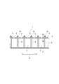
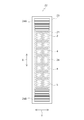
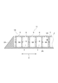
- FIG. 1 is a plan view of a shoe sole cleaning device including a moving body cleaning mat according to a first embodiment of the present disclosure.
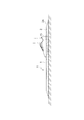
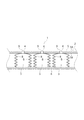
- 1 is a cross-sectional view of a shoe sole cleaning device including a moving body cleaning mat according to a first embodiment of the present disclosure. It is a figure which shows the use condition of the shoe sole washing
- FIG. 3 is a cross-sectional view for explaining a structure in which a bottom portion forming a pump chamber portion is detachable in the moving body washing mat (shoe bottom washing mat) according to the first embodiment of the present disclosure.
- FIG. 5 is a cross-sectional view showing an example in which a contact prevention portion is provided in the moving body cleaning mat according to the first embodiment of the present disclosure. It is sectional drawing which shows the other example of the contact prevention part provided in the moving body cleaning mat which concerns on 1st embodiment of this indication. It is a top view of a tire washing device provided with a mobile body washing mat (tire washing mat) concerning a second embodiment of this indication. It is a figure which shows the use condition of the tire washing
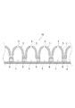
- FIG. 11 is a cross-sectional view showing an example in which a surface portion of a mat portion corresponding to a pump chamber portion of a moving body cleaning mat according to another embodiment of the present disclosure is formed in a protrusion shape.
- FIG. 11 is a cross-sectional view showing an example in which a surface portion of a mat portion corresponding to a pump chamber portion of a moving body cleaning mat according to another embodiment of the present disclosure is formed in a protrusion shape.
- FIG. 9 is a cross-sectional view showing an example in which the bottom of a moving body cleaning mat according to another embodiment of the present disclosure is fully opened.
- FIG. 11 is a cross-sectional view showing an example in which a surface portion of a mat portion corresponding to a pump chamber portion of a moving body cleaning mat according to another embodiment of the present disclosure is formed in a protrusion shape.
- FIG. 9 is a cross-sectional view showing an example in which the bottom of a moving body cleaning mat according to another embodiment of the present disclosure is fully
- FIG. 7 is a cross-sectional view showing an example in which a support member is provided on a side member of a moving body cleaning mat according to another embodiment of the present disclosure.
- FIG. 9 is a cross-sectional view illustrating a moving body cleaning mat according to another embodiment of the present disclosure, in which a bottom portion of the moving body cleaning mat is partially opened. It is sectional drawing which shows the modification of the side member of the moving body cleaning mat which concerns on other embodiment of this indication. It is sectional drawing which shows the modification of the side member of the moving body cleaning mat which concerns on other embodiment of this indication.
- the moving body cleaning mat according to this embodiment is one in which mechanical energy is directly transmitted from the moving body.
- the shoe sole cleaning mat will be described as an example in the first embodiment, and the tire cleaning mat will be described as an example in the second embodiment.
- the length direction of the shoe sole cleaning mat is defined as the longitudinal direction X and the width direction is defined as the lateral direction Y.
- the shoe sole cleaning mat 1 according to this embodiment is used to remove soil, sand, and dust (hereinafter referred to as adhered matter) adhering to the shoe sole by injecting a fluid onto the shoe sole. ..
- a shoe sole cleaning mat 1 according to this embodiment includes a mat (mat portion) 2 that receives a pressing force from the outside, and a plurality of pump chambers formed inside the mat 2.
- a (pump chamber) 3 and a discharge / suction hole 4 as a plurality of fluid discharge / suction parts provided in the mat 2 are provided.
- the mat 2 is housed in a frame member 2A having an inner peripheral wall corresponding to the outer shape of the mat 2, for example, and is used as a shoe sole cleaning device 11. As shown in FIG. 3, the shoe sole cleaning device 11 is installed so that a user walks on the shoe sole cleaning mat 1.
- the frame member 2 ⁇ / b> A is formed in a slope shape around the frame member 2 ⁇ / b> A and has a shape that does not trip when a pedestrian passes through the shoe sole cleaning device 11. Further, a protrusion or a slip stopper is formed on a portion of the frame member 2A that is in contact with the installation surface (for example, the floor surface), and the frame member 2A has a shape that is unlikely to slip on the installation surface.
- a member having a small elasticity can be used as the frame member 2A, and the frame member 2A plays a cushioning role between the installation surface and the shoe sole cleaning mat 1. Therefore, even if the shoe sole cleaning mat 1 expands or contracts, the frame member 2A is unlikely to shift with respect to the floor surface.
- the mat 2 connects the ceiling member 5 that forms the surface portion of the mat 2, the bottom member 6 that forms the bottom portion of the mat 2, and the ceiling member 5 and the bottom member 6, and forms the side wall of the pump chamber 3. And a plurality of side members (side portions) 8 (FIG. 2).
- the mat 2 has a rectangular shape, and the length of the mat 2 is designed to be longer than the stride of the user, for example.
- the mat 2 is made of an elastic material.
- the mat 2 is crushed when receiving a pressing force from the outside, and is restored to the original state when the pressing force from the outside is stopped. Since the mat 2 is repeatedly subjected to a pressing force from the outside, it is preferable to use a material having excellent restoring force and durability for this mat 2.
- an elastic member such as a rubber material can be used.
- the top member 5, the bottom member 6, and the side member 8 may be made of the same material or different materials. Further, a plurality of the mats 2 may be arranged vertically and horizontally and used.
- the bottom member 6 may be provided with a detachable portion 7 so that it can be detached from the side member 8.
- the attaching / detaching portion 7 the bottom member 6 can be easily removed, and the deposits and the like accumulated in the pump chamber 3 can be easily washed.
- the pump chamber 3 A plurality of pump chambers 3 are formed in each of the longitudinal direction X and the lateral direction Y.
- the pump chamber 3 has a top member 5 as an upper wall, a bottom member 6 as a lower wall, and side members 8 as side walls.
- the ceiling member 5 receives a pressing force from the outside, the ceiling member 5 is crushed and the side member 8 is deformed, so that the volume of the pump chamber 3 becomes smaller.
- the pump chamber 3 has various shapes such as a cube, a rectangular parallelepiped, a cylinder, and a cone. Further, the shape of the pump chamber 3 is determined in consideration of the difficulty of production, the efficiency of discharge and suction, and the like.
- the discharge / suction hole 4 is formed so as to penetrate the front surface 5A and the back surface 5B of the ceiling member 5, and the opening 9 of the discharge / suction hole 4 is formed in a circular shape.
- a plurality of the discharge suction holes 4 are provided at equal intervals in the longitudinal direction X and the lateral direction Y.
- the exhaust suction hole 4 plays a role as a flow path for air inside and outside the mat 2. Specifically, when the ceiling member 5 receives a pressing force from the outside, the fluid (air) inside the pump chamber 3 is discharged to the outside of the mat 2 via the discharge / suction hole 4.
- the discharge suction hole 4 may have various shapes such as an oval shape, a quadrangle shape, a star shape, a triangle shape, or a slit. In addition, it can be determined in consideration of the degree of difficulty of manufacturing, the efficiency of discharging and sucking air, and the like. The arrangement and number of the exhaust suction holes 4 are determined in consideration of the efficiency of exhaust suction of air.
- the ceiling member 5 of the mat 2 receives a pressing force from the shoe sole 15, and the side member 8 is crushed and deformed, so that the pump chamber 3 of the pump chamber 3 is deformed. The volume becomes smaller. Then, the air inside the pump chamber 3 is vigorously jetted from the exhaust suction hole 4 toward the shoe sole 15 (arrow F1). The injected air collides from below the shoe sole 15, and the impact of the collision removes deposits from the shoe sole 15. On the other hand, when the shoe sole 15 separates from the mat 2, the deformed pump chamber 3 is restored to its original state, so that the deposit is sucked into the pump chamber 3 (arrow F2).
- the adhering matter adhering to the shoe sole 15 can be removed by jetting (arrow F1) and suction (arrow F2). Further, since air is ejected from the pump chamber 3 stepped on the shoe sole 15, fluid is ejected from below the shoe sole 15, and air can be ejected to the groove portion of the shoe sole 15 as well. It is also possible to remove deposits attached to the.
- the pump chamber 3 corresponding to the place where the shoe sole 15 is stepped is deformed, but the other pump chambers 3 are not deformed. Therefore, the pressing force of the shoe sole 15 can be efficiently converted into the injection energy. As a result, the fluid is strongly jetted to the sole 15 (arrow F1).
- the top members 5 on the left and right sides of the surface in contact with the sole 15 also bends. Therefore, not only the volume of the pump chamber 3 corresponding to the surface directly receiving the pressing force from the shoe sole 15 but also the volume of the pump chamber 3 around it becomes small. Then, air is also jetted from around the shoe sole 15, and in addition to the shoe sole 15, the deposits around the shoe sole 15 are removed.
- the pump chamber 3 stepped on the shoe sole 15 efficiently receives a pressing force from the shoe sole 15 and the internal pressure of the pump chamber 3 is increased.
- the opening 9 of the discharge suction hole 4 faces toward the shoe sole 15 due to the nature of the mat, so that the air is absorbed by the shoe. It is jetted toward.
- a plurality of pump chambers 3 are provided and partitioned by the side member 8. Therefore, when the ceiling member 5 is pressed, air is internally circulated between the pump chambers 3. Or do not move. Therefore, air can be efficiently discharged or sucked through the discharge / suction hole 4.
- the shoe sole cleaning device 11 includes the shoe sole cleaning mat 1 inside the frame member 2A (FIG. 2), and these frame member 2A and shoe sole cleaning mat 1 are It can be manufactured integrally.
- the frame member 2A and the shoe sole cleaning mat 1 are integrally manufactured, the structure is simplified and the cost can be reduced.
- the arrangement or shape of the pump chamber 3 and the arrangement or shape of the discharge / suction hole 4 are determined by the type of fluid, the ejection efficiency of the fluid, the size of the moving body cleaning mat, the difficulty of production, the cost, and the like.
- the shoe sole cleaning device 11 that uses air as the fluid has been described, but the shoe sole cleaning device 11 may be applied to, for example, a device that is installed at the entrance of a food factory and sterilizes the shoe sole 15. You can also In this case, the shoe sole cleaning mat 1 is used by immersing it in a liquid antiseptic solution. Since the shoe sole cleaning device 11 can wash the shoe sole 15 by stepping on the shoe sole cleaning mat 1 many times, the shoe sole cleaning device 11 can be downsized and used. .. Further, by providing the shoe bottom cleaning device 11 in which air is jetted adjacent to the shoe sole washing device 11 using the disinfectant solution, the air jetted from the pump chamber 3 blows off the antiseptic solution to the shoe sole 15. It is possible to prevent the attached extra disinfectant solution from spreading to the surroundings.
- the top surface 5A of the top member 5 of the shoe sole cleaning mat 1 may be provided with a protrusion 16 as a shoe sole contact preventing member, as shown in FIG.
- the protrusion 16 has a conical shape and is provided between the discharge suction holes 4 adjacent to each other in the longitudinal direction X.
- the shape of the protrusion 16 is not limited to a conical shape, and for example, a rectangular parallelepiped shape can be used as shown in FIG. 7.
- a brush 17 may be provided on the front surface 5A of the ceiling member 5.
- the brush 17 plays a role of a shoe sole contact prevention member and also a role of scraping off an adhered matter fitted in a groove formed in the shoe sole 15.
- the adhesion preventing member is determined in consideration of the shape, arrangement, size, material, design, etc. of which the shoe sole 15 is unlikely to slip.
- the shoe sole cleaning device 11 provided with this shoe sole cleaning mat has an assembly work as compared with a shoe sole cleaning device using a motor or a power source. In addition to easy installation work, there is no burden on transportation work.
- the tire cleaning mat 21 as the moving body cleaning mat according to the present embodiment is used for ejecting a fluid to a tire of a vehicle to remove a deposit on the tire. Since the tire cleaning mat 21 has substantially the same basic structure, the same components are designated by the same reference numerals, and detailed description thereof will be omitted.
- the tire cleaning device 22 has a water tank 24 filled with water on the iron plate 23, and an inclination provided before and after the longitudinal direction X of the water tank 24.
- the members 24A and 24B are arranged, and the tire washing mat 21 is provided in the water tank 24.
- the inclined members 24A and 24B are slopes on which the vehicle rides on the water tank 24.
- the length of the tire cleaning mat 21 is designed to be equal to or longer than the outer circumference of the tire 25. Further, the tire cleaning mat 21 can be divided into a plurality of pieces and arranged side by side.
- the tire cleaning device 22 is installed at the entrance / exit of the construction truck.
- the arrangement or shape of the pump chamber 3 and the arrangement or shape of the discharge / suction hole 4 are determined depending on the type of fluid, the ejection efficiency of the fluid, the size of the moving body cleaning mat, the difficulty of production, the cost, and the like. Further, a rubber material or the like having an elastic force can be used as a member forming the mat 2.
- a moving body cleaning mat having the following configuration may be used.
- the ceiling member 5 of the mat 2 corresponding to the plurality of pump chambers 3 is formed in a protruding shape.
- the side member 8 is not provided.
- the moving body cleaning mat 1A can be manufactured at low cost because the pump chamber 3 is composed of the protruding top member 5 and the bottom member 6 and has a simple structure. By providing a reinforcing member inside the pump chamber 3 or changing the thickness of the ceiling member 5, the ceiling member 5 can be easily restored to its original state.
- the moving body cleaning mat 1B is formed by connecting the mat 2 of the moving body cleaning mat 1A to the bottom member 6 via the side member 8. Compared to the moving body cleaning mat 1A, the moving body cleaning mat 1B can increase the capacity of the pump chamber 3 by the amount of the side member 8 provided.
- the moving body cleaning mat 1C is different from the above-described moving body cleaning mat in that the bottom member 6 is not provided, that is, the bottom is completely opened.
- the lower portion of the side member 8 of the pump chamber 3 is provided so as to directly contact the frame member 2A and the water tank 24. Since this moving body cleaning mat 1C does not have the bottom member 6, it can be easily cleaned when cleaning adhering substances sucked into the pump chamber 3, and in addition, it is easy to manufacture.
- the moving body cleaning mat 1D has a side member 8 provided with a support member 8A.
- a sheet with a small elastic deformation (for example, a plastic sheet) is used for the support member 8A.
- a plurality of the support members 8A can be provided in the height direction of the moving body cleaning mat 1D.
- the support member 8A can prevent abnormal deformation of the pump chamber 3 when pressed, and can increase the strength of the moving body cleaning mat 1D.
- the moving body cleaning mat 1E has a through hole 6A formed in the bottom member 6 that constitutes the pump chamber 3. Therefore, a part of the bottom member 6 is open. Since the moving body cleaning mat 1E has the through holes 6A formed therein, it is possible to easily clean the adhering substances sucked into the pump chamber 3. Further, since the internal pressure of the pump chamber 3 acts vertically on each member, the internal pressure is applied to a portion of the bottom member 6 other than the through hole 6A, so that the frame member 2A, the water tank 24, and the bottom member 6 are separated from each other. It becomes difficult for the fluid to leak from the contacting parts.
- the side member 8 of the moving body cleaning mat 1 is not limited to the linear member in the height direction shown in the embodiment.
- the side member 8 may have a bellows-like structure in which a plurality of concave portions and convex portions are repeated in the height direction.
- the side members 8 composing the adjacent pump chambers 3 are provided at a predetermined interval, and the adjacent pump chambers 3 are partitioned by the side members 8.
- One end of the side member 8 is connected to the back surface 5B of the top member 5, and the other end of the side member 8 is connected to the bottom member 6.
- the side member 8 may be shared between the adjacent pump chambers 3.
- one ends of the side members 8 on both sides may be connected to the vicinity of the discharge / suction hole 4.
- one end of the side member 8 is connected to the vicinity of the discharge suction hole 4, so that when a pressing force is applied to the mat 2, the fluid inside the pump chamber 3 is moved to the side member. 8 is guided to the discharge suction hole 4. Therefore, the fluid can be smoothly ejected from the discharge suction hole 4.
- an elastically deformable member such as a spring (not shown) may be provided inside the pump chamber 3.
- the time required for restoration can be shortened, and the suction force of the fluid discharge / suction portion can be increased.
- an example in which one fluid discharge suction hole 4 is provided in one pump chamber 3 is shown, but the number of fluid discharge suction holes 4 is not limited to one, and a plurality of fluid discharge suction holes 4 may be formed.
- the shoe sole cleaning device 11 and the tire cleaning device 22 have been described, but in addition to this, the configurations described in the above-described embodiments are selected without departing from the gist of the present invention. , It is possible to change to other configurations as appropriate.
Landscapes
- Engineering & Computer Science (AREA)
- Mechanical Engineering (AREA)
- Vehicle Cleaning, Maintenance, Repair, Refitting, And Outriggers (AREA)
Abstract
La présente invention concerne un tapis de nettoyage de corps mobile qui, avec une structure simple, est capable de nettoyer un corps mobile sans nécessiter une alimentation en énergie depuis l'extérieur, par conversion de l'énergie du corps mobile pour éjecter de l'énergie d'un liquide. Le tapis de nettoyage de corps mobile est pourvu : d'un tapis qui reçoit une force de pression provenant d'un corps mobile; d'une pluralité de trous d'évacuation/ d'aspiration de liquide disposés dans une section de surface externe du tapis; et d'une pluralité de chambres de pompe qui sont formées à l'intérieur du tapis et dans lesquelles est stocké un liquide devant être évacué ou aspiré à travers les trous d'évacuation/ d'aspiration de liquide. Le tapis de nettoyage de corps mobile est configuré de telle sorte que les chambres de pompe sont déformées et le liquide est éjecté sur le corps mobile en raison de la force de pression générée par le corps mobile se déplaçant sur la section de surface externe du tapis.
Priority Applications (3)
| Application Number | Priority Date | Filing Date | Title |
|---|---|---|---|
| JP2020553907A JPWO2020090761A1 (ja) | 2018-10-31 | 2019-10-28 | 移動体洗浄マット |
| CN201980086484.7A CN113226147A (zh) | 2018-10-31 | 2019-10-28 | 移动体清洗垫 |
| PCT/JP2019/042227 WO2020090761A1 (fr) | 2018-10-31 | 2019-10-28 | Tapis de nettoyage de corps mobile |
Applications Claiming Priority (4)
| Application Number | Priority Date | Filing Date | Title |
|---|---|---|---|
| JPPCT/JP2018/040525 | 2018-10-31 | ||
| PCT/JP2018/040525 WO2020090037A1 (fr) | 2018-10-31 | 2018-10-31 | Tapis de nettoyage de pneu |
| PCT/JP2018/047215 WO2020129233A1 (fr) | 2018-12-21 | 2018-12-21 | Tapis de nettoyage de semelle de chaussure |
| JPPCT/JP2018/047215 | 2018-12-21 |
Publications (1)
| Publication Number | Publication Date |
|---|---|
| WO2020090130A1 true WO2020090130A1 (fr) | 2020-05-07 |
Family
ID=70463972
Family Applications (1)
| Application Number | Title | Priority Date | Filing Date |
|---|---|---|---|
| PCT/JP2019/007650 Ceased WO2020090130A1 (fr) | 2018-10-31 | 2019-02-27 | Tapis de nettoyage de corps mobile |
Country Status (3)
| Country | Link |
|---|---|
| JP (1) | JPWO2020090761A1 (fr) |
| CN (1) | CN113226147A (fr) |
| WO (1) | WO2020090130A1 (fr) |
Cited By (3)
| Publication number | Priority date | Publication date | Assignee | Title |
|---|---|---|---|---|
| CN111973776A (zh) * | 2020-09-01 | 2020-11-24 | 武汉轻工大学 | 一种猪场用消毒垫 |
| GB2595832A (en) * | 2021-09-14 | 2021-12-08 | Butler Michael | Vehicle tyre detailing mats |
| WO2022097494A1 (fr) * | 2020-11-06 | 2022-05-12 | 健一 中島 | Machine de nettoyage de semelle de chaussure |
Citations (4)
| Publication number | Priority date | Publication date | Assignee | Title |
|---|---|---|---|---|
| JPS6342055B2 (fr) * | 1983-09-14 | 1988-08-19 | Kikusui Kagaku Kogyo Kk | |
| JPH10179367A (ja) * | 1996-10-28 | 1998-07-07 | Kyowa:Kk | 保水性除菌マット及びその形成方法並びにその施用方法 |
| KR20150090797A (ko) * | 2014-01-29 | 2015-08-06 | 김병철 | 신발의 소독 및 털이가 가능한 발판 |
| KR101695678B1 (ko) * | 2015-10-26 | 2017-01-12 | 주식회사지티이 | 방역용 온열소독매트 |
Family Cites Families (3)
| Publication number | Priority date | Publication date | Assignee | Title |
|---|---|---|---|---|
| JP2010183934A (ja) * | 2009-02-10 | 2010-08-26 | Semutekku:Kk | 汚れ防止用マットおよび汚れ防止方法 |
| KR101728278B1 (ko) * | 2016-05-16 | 2017-04-18 | 정충호 | 발 매트 |
| CN107260106A (zh) * | 2017-08-19 | 2017-10-20 | 贵州工程应用技术学院 | 水喷射鞋底清洗装置 |
-
2019
- 2019-02-27 WO PCT/JP2019/007650 patent/WO2020090130A1/fr not_active Ceased
- 2019-10-28 CN CN201980086484.7A patent/CN113226147A/zh active Pending
- 2019-10-28 JP JP2020553907A patent/JPWO2020090761A1/ja active Pending
Patent Citations (4)
| Publication number | Priority date | Publication date | Assignee | Title |
|---|---|---|---|---|
| JPS6342055B2 (fr) * | 1983-09-14 | 1988-08-19 | Kikusui Kagaku Kogyo Kk | |
| JPH10179367A (ja) * | 1996-10-28 | 1998-07-07 | Kyowa:Kk | 保水性除菌マット及びその形成方法並びにその施用方法 |
| KR20150090797A (ko) * | 2014-01-29 | 2015-08-06 | 김병철 | 신발의 소독 및 털이가 가능한 발판 |
| KR101695678B1 (ko) * | 2015-10-26 | 2017-01-12 | 주식회사지티이 | 방역용 온열소독매트 |
Cited By (6)
| Publication number | Priority date | Publication date | Assignee | Title |
|---|---|---|---|---|
| CN111973776A (zh) * | 2020-09-01 | 2020-11-24 | 武汉轻工大学 | 一种猪场用消毒垫 |
| WO2022097494A1 (fr) * | 2020-11-06 | 2022-05-12 | 健一 中島 | Machine de nettoyage de semelle de chaussure |
| JP7076056B1 (ja) * | 2020-11-06 | 2022-05-26 | 健一 中島 | 靴底洗浄装置 |
| GB2595832A (en) * | 2021-09-14 | 2021-12-08 | Butler Michael | Vehicle tyre detailing mats |
| GB2595832B (en) * | 2021-09-14 | 2022-06-29 | Butler Michael | Vehicle tyre detailing mats |
| WO2023041206A1 (fr) * | 2021-09-14 | 2023-03-23 | Michael Butler | Tapis d'entretien esthétique de pneu de véhicule |
Also Published As
| Publication number | Publication date |
|---|---|
| CN113226147A (zh) | 2021-08-06 |
| JPWO2020090761A1 (ja) | 2021-09-30 |
Similar Documents
| Publication | Publication Date | Title |
|---|---|---|
| US5588176A (en) | Water recovery wash brush | |
| JPWO2020090761A1 (ja) | 移動体洗浄マット | |
| JP7576247B2 (ja) | コンクリート斫り装置及びコンクリート斫り方法 | |
| US20160120385A1 (en) | Surface maintenance vehicle with an integrated water trap for trapping residual waste | |
| KR101062704B1 (ko) | 노면용 건식청소장비 | |
| US20230119367A1 (en) | Mat for cleaning and moving body cleaning device | |
| JP7030209B2 (ja) | タイヤ洗浄マット | |
| JP2016032970A (ja) | タイヤの洗浄構造および洗浄装置 | |
| WO2020090761A1 (fr) | Tapis de nettoyage de corps mobile | |
| WO2020129233A1 (fr) | Tapis de nettoyage de semelle de chaussure | |
| US7743459B2 (en) | Floor washing-drying machine | |
| KR100761762B1 (ko) | 로봇청소기 | |
| KR101769964B1 (ko) | 운반대차의 바퀴 세척장치 | |
| KR101865005B1 (ko) | 자동차 세차용 다목적 브러쉬 | |
| JP5456566B2 (ja) | 車両のタイヤ洗浄装置および洗浄方法 | |
| CN111263713B (zh) | 车辆用附着物去除装置 | |
| KR200251093Y1 (ko) | 노면 청소용 고압 분사 노즐을 구비한 노면 청소차 | |
| KR20180126404A (ko) | 바닥 청소기용 스퀴지 | |
| KR200421046Y1 (ko) | 자동차용 하부 세차 장치 | |
| KR102134262B1 (ko) | 적설 수거 이송 장치 및 이를 이용한 적설 수거 이송 방법 | |
| KR100635641B1 (ko) | 세척수가 비산되는 로봇 청소기 | |
| AU2005232272B2 (en) | A Shaker Grid | |
| KR20060057298A (ko) | 거울의 성에 방지 장치 | |
| KR101344350B1 (ko) | 세척물 분사장치 | |
| TWI645995B (zh) | car washer |
Legal Events
| Date | Code | Title | Description |
|---|---|---|---|
| 121 | Ep: the epo has been informed by wipo that ep was designated in this application |
Ref document number: 19879366 Country of ref document: EP Kind code of ref document: A1 |
|
| NENP | Non-entry into the national phase |
Ref country code: DE |
|
| 122 | Ep: pct application non-entry in european phase |
Ref document number: 19879366 Country of ref document: EP Kind code of ref document: A1 |
|
| NENP | Non-entry into the national phase |
Ref country code: JP |