WO2020090166A1 - Dispositif de traitement de signal, capteur d'image, dispositif de capture d'image et dispositif de traitement d'informations - Google Patents
Dispositif de traitement de signal, capteur d'image, dispositif de capture d'image et dispositif de traitement d'informations Download PDFInfo
- Publication number
- WO2020090166A1 WO2020090166A1 PCT/JP2019/029085 JP2019029085W WO2020090166A1 WO 2020090166 A1 WO2020090166 A1 WO 2020090166A1 JP 2019029085 W JP2019029085 W JP 2019029085W WO 2020090166 A1 WO2020090166 A1 WO 2020090166A1
- Authority
- WO
- WIPO (PCT)
- Prior art keywords
- signal
- unit
- processing device
- pixel
- vsl
- Prior art date
- Legal status (The legal status is an assumption and is not a legal conclusion. Google has not performed a legal analysis and makes no representation as to the accuracy of the status listed.)
- Ceased
Links
Images


Classifications
-
- H—ELECTRICITY
- H04—ELECTRIC COMMUNICATION TECHNIQUE
- H04N—PICTORIAL COMMUNICATION, e.g. TELEVISION
- H04N25/00—Circuitry of solid-state image sensors [SSIS]; Control thereof
- H04N25/70—SSIS architectures; Circuits associated therewith
- H04N25/76—Addressed sensors, e.g. MOS or CMOS sensors
- H04N25/78—Readout circuits for addressed sensors, e.g. output amplifiers or A/D converters
-
- H—ELECTRICITY
- H03—ELECTRONIC CIRCUITRY
- H03M—CODING; DECODING; CODE CONVERSION IN GENERAL
- H03M1/00—Analogue/digital conversion; Digital/analogue conversion
- H03M1/12—Analogue/digital converters
- H03M1/14—Conversion in steps with each step involving the same or a different conversion means and delivering more than one bit
-
- H—ELECTRICITY
- H03—ELECTRONIC CIRCUITRY
- H03M—CODING; DECODING; CODE CONVERSION IN GENERAL
- H03M1/00—Analogue/digital conversion; Digital/analogue conversion
- H03M1/12—Analogue/digital converters
- H03M1/48—Servo-type converters
-
- H—ELECTRICITY
- H03—ELECTRONIC CIRCUITRY
- H03M—CODING; DECODING; CODE CONVERSION IN GENERAL
- H03M1/00—Analogue/digital conversion; Digital/analogue conversion
- H03M1/12—Analogue/digital converters
- H03M1/50—Analogue/digital converters with intermediate conversion to time interval
- H03M1/56—Input signal compared with linear ramp
Definitions
- the technology disclosed in the present specification relates to a signal processing apparatus that performs single-slope AD conversion, an image sensor used as a column ADC using the signal processing apparatus, an imaging apparatus, and an information processing apparatus.
- Solid-state imaging devices include amplification type solid-state imaging devices represented by MOS image sensors such as CMOS (Complementary Metal Oxide Semiconductor) and charge transfer type solid-state imaging devices represented by CCD (Charge Coupled Device) image sensors. ing. These solid-state imaging devices are widely used in digital still cameras, digital video cameras, and various information terminals such as smartphones and tablets.
- MOS image sensors such as CMOS (Complementary Metal Oxide Semiconductor)
- CCD Charge Coupled Device
- CMOS image sensors are widely used because of their low power supply voltage and power consumption.
- the CMOS image sensor also has an advantage that various functional circuits can be integrated in the same element. In particular, by mounting the AD converter in the same element and performing digital output, it is possible to reduce the influence of noise mixed during the processing of the pixel signal.
- the CMOS image sensor has an AD converter (AD Converter: ADC) that performs AD (Analog to Digital) conversion of an analog electric signal output by a pixel having a photoelectric conversion element such as a PD (Photo Diode) that performs photoelectric conversion.
- AD converter Analog to Digital
- a column AD conversion method is generally used in which AD converters are mounted in parallel in the row direction and the analog signals photoelectrically converted by pixels are AD-converted for each row and read.
- SSADC single-slope AD converter
- a comparator compares a reference signal called a ramp signal whose level changes with a constant slope with an electric signal output from a pixel, and a counter makes the levels of the reference signal and the electric signal coincide with each other.
- the electric signals output from the pixels are AD-converted by counting the time required to change the level of the reference signal up to.
- the CDS for obtaining the difference between the AD conversion result of the reset level which is the electric signal immediately after the pixel is reset and the AD conversion result of the signal level which is the electric signal corresponding to the charges accumulated in the PD of the pixel after the reset (Correlated Double Sampling: Correlated double sampling) is performed, and the difference obtained as a result of the CDS is output as a pixel value (for example, see Patent Document 1).
- the conventional SSADC it has become difficult for the conventional SSADC to meet all the requirements of high precision (or multi-bit), high speed (or high frame rate), and low power consumption. For example, as the resolution becomes higher as the number of bits increases, the count period increases, so that the AD conversion time becomes longer, the signal reading from the pixel becomes slower, and eventually high-speed imaging cannot be performed.
- the resolution of the SSADC is determined by the number of clocks that generate the ramp, but considering that the clock speed has already reached the upper limit, the AD conversion period doubles each time the resolution increases by 1 bit, resulting in higher accuracy. There is a limit to the compatibility of high speed operation with. If an attempt is made to improve the accuracy of the current 12 bits to 14 bits, the AD processing time will be quadrupled, resulting in a strict frame rate and increased power consumption of the ADC. As a solution for speeding up, there is AD cascading (or parallel processing), but further power consumption increases and there is a mounting problem.
- the object of the technique disclosed in the present specification is a signal processing device that performs single slope type AD conversion that realizes high accuracy, high speed, and low power consumption, and column AD conversion that enables high accuracy and high speed conversion.
- An object of the present invention is to provide an image sensor, an image pickup apparatus, and an information processing apparatus including a container.
- An amplifier that amplifies the analog signal
- a determination unit that determines the higher-order bits of the analog signal
- An adjustment unit that adjusts the level of the analog signal input to the amplifier based on the determination result of the determination unit
- a single-slope AD converter that AD-converts the lower bits of the analog signal using the level-adjusted output signal
- the judging unit is composed of an inverter, a capacitor, and a switch element, and judges the upper bit of the analog signal before being input to the amplifier.
- the determining unit determines the upper bit of the analog signal during D-phase settling in AD conversion of the analog signal. Further, the upper bit determined by the determination unit and the lower bit output from the AD conversion unit are connected to output a digital signal obtained by AD converting the analog signal.
- a signal processing device that performs single-slope AD conversion that achieves high accuracy, high speed, and low power consumption, and column AD conversion that enables high accuracy and high speed conversion. It is possible to provide an image sensor including a container, an imaging device, and an information processing device.
- FIG. 1 is a diagram showing a configuration example of the image sensor 100.
- FIG. 2 is a diagram showing a main configuration example of the pixel array 101.
- FIG. 3 is a diagram showing an example of a main circuit configuration of the unit pixel 141.
- FIG. 4 is a diagram schematically showing a configuration example of the AD conversion unit 103.
- FIG. 5 is a diagram schematically illustrating an internal configuration example of the column AD conversion unit 161 that performs AD conversion by the single slope method.
- FIG. 6 is a diagram showing a timing chart when AD conversion is performed by the correlated double sampling method.
- FIG. 7 is a diagram showing each processing phase of AD conversion when the D-phase period is shortened.
- FIG. 8 is a diagram for explaining the D-phase comparison process in the multi-lamp method.
- FIG. 1 is a diagram showing a configuration example of the image sensor 100.
- FIG. 2 is a diagram showing a main configuration example of the pixel array 101.
- FIG. 3 is a diagram
- FIG. 9 is a diagram for explaining the D phase comparison processing in the VSL shift method.
- FIG. 10 is a diagram showing a schematic configuration example of a signal processing circuit 1000 for AD converting the pixel signal VSL by the VSL shift method.
- FIG. 11 is a diagram showing a specific circuit configuration example of the adjusting unit 1002 and the column amplifier 160.
- FIG. 12 is a diagram showing an operation example of the adjusting unit 1002.
- FIG. 13 is a diagram showing an example of the level shift operation of the pixel signal VSL by the adjustment unit 1002.
- FIG. 14 is a diagram showing a circuit configuration example of the determination unit 1001.
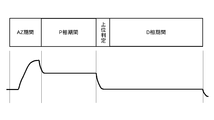
- FIG. 15 is a diagram showing an operation timing chart of the determination unit 1001 in each processing phase of AD conversion.
- FIG. 16 is a diagram showing an operation example of the determination unit 1001.
- FIG. 17 is a diagram showing an operation example of the determination unit 1001.
- FIG. 18 is a diagram showing the relationship between the 4-bit determination result of the inverter 1401 and the upper 2 bits output from the determination unit 1001.
- FIG. 19 is a diagram showing a configuration example of the image pickup apparatus 1900.
- FIG. 20 is a diagram showing a configuration example of the information processing device 2000.
- FIG. 1 shows a configuration example of an image sensor 100 to which the technique disclosed in this specification is applied.
- the image sensor 100 is a device that photoelectrically converts light from a subject and outputs it as image data, and is configured as a CMOS image sensor, a CCD image sensor, or the like.
- the illustrated image sensor 100 includes a pixel array 101, a reference voltage generation unit 102, an AD conversion unit 103, a horizontal transfer unit 104, a control unit 111, and a vertical scanning unit 112.
- the pixel array 101 is a pixel region in which unit pixels each having a photoelectric conversion element such as a PD are arranged in a plane or a curved surface.
- the analog signal read from each unit pixel is transmitted to the AD conversion unit 103 via any of the vertical signal lines 121-1 to 121-N.
- the vertical signal lines 121-1 to 121-N will be collectively referred to as the vertical signal lines 121 unless it is necessary to distinguish them from each other.
- the reference voltage generator 102 generates a reference signal (also referred to as a reference voltage) that serves as a reference signal for AD conversion by the AD converter 103.
- a ramp (Ramp) signal composed of a ramp wave (sawtooth wave) is used as a reference signal.
- the reference voltage generator 102 has, for example, a DA (Digital to Analog) converter (not shown), and the DA converter generates a ramp signal. This ramp signal is supplied to the AD conversion unit 103 via the reference signal line 122.
- the AD conversion unit 103 uses the reference signal to AD convert each analog signal read from each unit pixel in the pixel array 101 via the vertical signal lines 121-1 to 121-N. , And outputs the digital data for each column to the horizontal transfer unit 104 via the corresponding signal line of the signal lines 123-1 to 123-N.
- the signal lines 123-1 to 123-N are collectively referred to as the signal line 123 unless it is necessary to distinguish them from each other.
- the horizontal transfer unit 104 transfers the digital data supplied from the AD conversion unit 103 via the signal line 123 to the outside of the image sensor 100 via the signal line 124.
- the control unit 111 controls the operation of the entire image sensor 100 by controlling each unit of the image sensor 100. Specifically, the control unit 111 controls an operation such as generation of a ramp signal by the reference voltage generation unit 102 by supplying a control signal via the control line 131. In addition, the control unit 111 controls the AD conversion operation of the pixel signal (VSL) by the AD conversion unit 103 by supplying the control signal via the control line 132. The control unit 111 also controls the digital data transfer operation by the horizontal transfer unit 104 by supplying a control signal via the control line 133. Further, the control unit 111 controls the vertical scanning of the pixel array 101 by the vertical scanning unit 112 by supplying a control signal via the control line 134.
- the vertical scanning unit 112 controls the operation of the transistor of each unit pixel of the pixel array 101 by being controlled by the control unit 111 and supplying a control signal via the control lines 125-1 to 125-M. ..
- the control lines 125-1 to 125-M are collectively referred to as the control lines 125 unless it is necessary to distinguish them from each other.
- FIG. 2 shows a main configuration example of the pixel array 101.
- the pixel array 101 includes a plurality of unit pixels arranged in a plane.
- M ⁇ N unit pixels 141 (unit pixels 141-11 to unit pixels 141-MN) are arranged side by side in a matrix of M rows and N columns (array).
- M and N are arbitrary natural numbers).
- the unit pixels 141-11 to 141-MN are collectively referred to as the unit pixel 141 unless it is necessary to distinguish them from each other.
- the arrangement of the unit pixels 141 is arbitrary, and may be arranged other than the matrix, such as a so-called honeycomb structure.
- a vertical signal line 121 (vertical signal line 121-1 to vertical signal line 121-N) is formed for each column of the unit pixel 141 (hereinafter, also referred to as a unit pixel column). Then, each vertical signal line 121 is connected to each unit pixel of a column (unit pixel row) corresponding to itself, and a signal read from each unit pixel is sent to the AD conversion unit 103 (not shown in FIG. 2). To transmit.
- a control line 125 (control line 125-1 to control line 125-M) is formed for each row of unit pixels 141 (hereinafter, also referred to as a unit pixel row). Then, each control line 125 is connected to each unit pixel 141 of the unit pixel row corresponding to itself, and transmits the control signal supplied from the vertical scanning unit 112 to each unit pixel 141.
- the unit pixel 141 is connected to the vertical signal line 121 assigned to the column to which it belongs (unit pixel column) and the control line 125 assigned to the unit pixel row to which it belongs, and the control line 125 thereof.
- the electric signal obtained by itself is supplied to the AD conversion unit 103 via the vertical signal line 121.
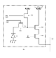
- FIG. 3 shows a main circuit configuration example of the unit pixel 141.
- the unit pixel 141 shown in the figure includes a photodiode (PD) 151, a transfer transistor 152, a reset transistor 153, an amplification transistor 154, and a select transistor 155.
- PD photodiode
- the unit pixels 141-11 to 141-MN have the same configuration.
- the photodiode 151 photoelectrically converts the received light into a photocharge having a charge amount corresponding to the light amount, and accumulates the photocharge. The accumulated photocharge is read at a predetermined timing.
- the anode electrode of the photodiode 151 is connected to the ground of the pixel region (pixel ground), and the cathode electrode is connected to the floating diffusion (FD) via the transfer transistor 152.
- the cathode electrode of the photodiode 151 may be connected to a power source (pixel power source) in the pixel region, the anode electrode may be connected to the FD via the transfer transistor 152, and photocharges may be read out as photoholes.
- the transfer transistor 152 controls the reading of photocharges from the photodiode 151.
- the transfer transistor 152 has a drain electrode connected to the FD and a source electrode connected to the cathode electrode of the photodiode 151.
- a transfer control line (TRG) that transfers a transfer control signal supplied from the vertical scanning unit 112 is connected to the gate electrode of the transfer transistor 152. This TRG is included in the control line 125 in FIG.
- the photoelectric charge is not transferred from the photodiode 151 (the photoelectric charge is accumulated in the photodiode 151).
- the signal of TRG is on, the photocharges accumulated in the photodiode 151 are transferred to the FD.
- the reset transistor 153 resets the FD potential.
- the reset transistor 153 has a drain electrode connected to the power supply potential and a source electrode connected to the FD.
- a reset control line (RST) that transmits a reset control signal supplied from the vertical scanning unit 112 is connected to the gate electrode of the reset transistor 153. This RST is included in the control line 125 in FIG.
- the FD is disconnected from the power supply potential when the signal of RST (that is, the gate potential of the reset transistor 153) is in the off state.
- the signal of RST that is, the gate potential of the reset transistor 153
- the RST signal is in the ON state
- the electric charge of the FD is discarded in the power supply potential and the FD is reset.
- the amplification transistor 154 amplifies the potential change of the FD and outputs it as an electric signal (analog signal).
- the amplification transistor 154 has a gate electrode connected to the FD, a drain electrode connected to the source follower power supply voltage, and a source electrode connected to the drain electrode of the select transistor 155.
- the amplification transistor 154 outputs the potential of the FD reset by the reset transistor 153 to the select transistor 155 as a reset signal (reset level). Further, the amplification transistor 154 outputs the potential of the FD to which the photocharge is transferred by the transfer transistor 152 to the select transistor 155 as a pixel signal (light accumulation signal level).
- the select transistor 155 controls the output of the electric signal supplied from the amplification transistor 154 to the vertical signal line (VSL) 121 (that is, the AD conversion unit 103).
- the select transistor 155 has a drain electrode connected to the source electrode of the amplification transistor 154 and a source electrode connected to the vertical signal line 121.
- a select control line (SEL) that transmits a select control signal supplied from the vertical scanning unit 112 is connected to the gate electrode of the select transistor 155. This SEL is included in the control line 125 in FIG.
- the amplification transistor 154 and the vertical signal line 121 are electrically disconnected. Therefore, in this state, the reset signal or the pixel signal is not output from the unit pixel 141.
- the unit pixel 141 is in the selected state. That is, the amplification transistor 154 and the vertical signal line 121 are electrically connected, and the signal output from the amplification transistor 154 is supplied to the vertical signal line 121 as the pixel signal VSL of the unit pixel 141. That is, the reset signal and the pixel signal VSL are read from the unit pixel 141.
- FIG. 4 schematically shows a configuration example of the AD converter 103.
- the illustrated AD conversion unit 103 has N column AD conversion units 161-1 to 161-N corresponding to the number of columns of the unit pixel 141 of the pixel array 101.
- the column AD conversion units 161-1 to 161-N are collectively referred to as the column AD conversion unit 161, unless it is necessary to distinguish them from each other.
- the column AD converter 161 is provided for each column (unit pixel row) of the pixel array 101.
- Each column AD conversion unit 161 (column AD conversion unit 161-1 to column AD conversion unit 161-N) has a vertical signal line 121 (vertical signal line 121-1 to vertical signal line 121-N) of a column corresponding to itself. ) And the reference signal line 122 are connected. Further, column amplifiers 160-1 to 160-N for amplifying pixel signals are inserted on the vertical signal lines 121-1 to 121-N of each column. Hereinafter, the column amplifiers 160-1 to 160-N are collectively referred to as the column amplifier 160 unless it is necessary to distinguish them from each other. In the column amplifier 160, before the pixel signal VSL transferred through the vertical signal line 121 is input to the column AD conversion unit 161, VSL is low-noise amplified and inverted output is performed.
- the column AD conversion unit 161 performs AD conversion by the single slope method. That is, each column AD converter 161 reads out the signal read from the unit pixel 141 of the column corresponding to itself and supplied through the vertical signal line 121 of the column (after being amplified by the column amplifier 160). AD conversion is performed using the reference signal supplied from the reference voltage generation unit 102 via the reference signal line 122.
- the signal line 123 (signal line 123-1 to signal line 123-N) of the column corresponding to the column AD conversion unit 161 is connected to each column AD conversion unit 161.
- Each column AD conversion unit 161 supplies the AD conversion result obtained by itself to the horizontal transfer unit 104 (not shown in FIG. 4) via the signal line 123 corresponding to itself.
- a control line 132 (control lines 132-1 to 132-N) is connected to each column AD converter 161.
- Each column AD converter 161 is driven based on a control signal (that is, control of the controller 111) supplied from the controller 111 (not shown in FIG. 4) via the control line 132 corresponding to itself.
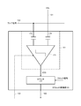
- FIG. 5 schematically shows an internal configuration example of the column AD conversion unit 161 that performs AD conversion by the single slope method.
- the illustrated column AD converter 161 includes a comparator 171, a counter 172, a capacitor 173, and a capacitor 174.
- One input terminal of the 2-input 1-output comparator 171 is connected to the vertical signal line 121 of the column corresponding to itself via the capacitor 174, and is read from each unit pixel of the column corresponding to itself.
- the pixel signal VSL is subjected to low noise amplification by the corresponding column amplifier 160, and then input via the capacitor 174.
- the other input terminal of the comparator 171 is connected to the reference signal line 122 via the capacitor 173, and the ramp signal generated as the reference signal by the reference voltage generation unit 102 is input.
- the output terminal VCO of the comparator 171 is connected to the counter 172.
- the capacitors 173 and 174 are capacitors having a fixed capacity (having a predetermined capacity). Note that the comparator 171, the capacitors 173, and 174 may be integrated into a comparator 181 (in other words, the capacitors 173 and 174 may be included in the configuration of the comparator 181).
- the comparator 171 receives the VSL signal (however, after low noise amplification by the column amplifier 160) input to one input terminal via the vertical signal line 121 and the capacitor 174, and the reference signal line 122 and the capacitor 173. The signal levels of the ramp signal input to the other input terminal are compared, and the comparison result is output to the counter 172. That is, the comparator 171 outputs a signal indicating which of the VSL signal and the ramp signal has the higher signal level from the output terminal VCO and supplies the signal to the counter 172.
- the signal output by the comparator 171 is, for example, 1-bit digital data.
- the value output by the comparator 171 becomes "0".
- the comparator 171 The value output by is "1".
- the bit length of the signal indicating the comparison result is arbitrary and may be information composed of a plurality of bits.
- the counter 172 has an input terminal connected to the output terminal VCO of the comparator 171, and an output terminal connected to the signal line 123 of the column corresponding to itself.
- the comparison result is supplied from the comparator 171 to the counter 172.
- the counter 172 counts the number of clocks of the clock signal from the start of counting until the comparison result of the comparator 171 is inverted (that is, the signal level of the output terminal VCO changes), and thus the time until the comparison result is inverted To measure. Then, the counter 172 converts the count value up to that point when the comparison result is inverted into the AD conversion result of the VSL signal input to one input terminal of the comparator 171 (that is, the signal read from the unit pixel 141). Of the digital data) is output to the horizontal transfer unit 104 via the signal line 123.
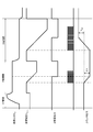
- FIG. 6 shows a timing chart when the AD conversion by the correlated double sampling method is performed in the column AD converter 161.
- the auto zero (AZ) period time t0 to time t1 of the correlated double sampling (comparator 171) and the reset signal and the ramp signal read from the pixel are compared P ( It includes a precharge phase period (time t1 to time t2) and a D (data) phase period (time t2 to time t3) in which the VSL signal read from the pixel and the ramp signal are compared.
- the analog image signal VSL read by the vertical signal line 121 is compared with a ramp signal which is a reference signal in signal level (voltage) by a comparator 171 in the column AD converter 103 arranged for each column. ..
- the counter 172 in the same column AD converter 161 operates.
- the analog pixel signal VSL of the vertical signal line 121 is converted into a digital pixel signal.
- the change in the reference voltage V slop is to convert the change in voltage into a change in time, and by counting the time with a predetermined clock, the analog value is converted into a digital value.
- the output of the comparator 171 is inverted from high level to low level. Then, in response to the polarity reversal of the comparator 171, the counter 171 stops the counting operation and temporarily holds the count value ⁇ P corresponding to the P-phase output ( ⁇ V).
- the output of the comparator 171 changes from high level to low level. Invert. Then, in response to the polarity reversal of the comparator 171, the counter 172 stops the counting operation and temporarily holds the count value ⁇ D corresponding to the D-phase output.
- correlated double sampling that is, subtracting the count value ⁇ P of the P phase period from the count value ⁇ D of the D phase period, it is possible to obtain the output voltage V out which is the difference between the D phase output and the P phase output. it can.
- the D phase period that is, the count value ⁇ D increases.
- the D phase period will be quadrupled, and the frame rate will be severe, and the ADC Increases power consumption.
- the multi-ramp method and the VSL shift method can be mentioned as the method for realizing the speedup of the single slope type AD conversion unit.
- the upper bit of the pixel signal VSL is determined in the upper determination period provided during the D-phase settling, and then the level comparison between the VSL and the ramp signal is performed in detail only in the lower level of VSL. Therefore, the D-phase period is shortened (see FIG. 7).
- the former multi-ramp method is, for example, a method of determining the upper bits of VSL in the D phase in N stages and generating N ramp signals having different levels corresponding to the upper bits (see, for example, Patent Document 2). See). Specifically, one corresponding ramp signal is selected from N based on the determination result of the upper bit, the comparison with VSL is performed, and the lower bit is measured.
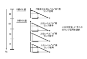
- FIG. 8 shows how the D-phase full scale (FS) is divided into four to generate ramp signals for each of the four voltage regions.
- the upper determination period it is determined which of the four voltage ranges the VSL level of the D phase corresponds to. Then, in the subsequent D-phase period, the ramp signal corresponding to the determination result of the upper bit is selected and compared with the pixel signal VSL.
- the D-phase period can be shortened to 1/4 as compared with the case where the comparison with VSL is performed on a full scale.
- the same ramp-shaped waveform signal for 12 bits is used as the multi-ramp and the upper bit ( 00, 01, 10, 11)
- four types of ramp signals having different levels can be generated.
- the upper 2 bits are determined in the upper determination period.
- the ramp signal of the corresponding level is selected and compared with the D-phase pixel signal VSL to determine the correlation of the lower 12 bits.
- Perform double sampling Then, 2 bits acquired in the upper determination period can be concatenated with the obtained upper 12 bits of the lower 12 bits to be converted into 14-bit digital data.
- the D-phase period can be shortened to 1/4 as compared with the case where the comparison with VSL is performed on a full scale.
- the multi-lamp is a system that selects the ramp signal according to the pixel level read out, and can be realized with a simple circuit configuration.
- the load capacitance applied to each ramp generation circuit changes, resulting in a delay, and as a result, There is a problem that the A / D conversion value shifts. Further, in order to correct the delay error, calibration for every 1H is necessary, and the circuit scale increases.
- the latter VSL shift method is a method of shifting the VSL level in the D-phase period. Specifically, the level of VSL in the D phase is determined in N steps, and the level of VSL in the D phase is shifted based on the determination result so that the input signal to the comparator 171 corresponds to N minutes of the D phase period. The D-phase period is shortened to 1 / N so that the voltage falls within the voltage range of 1. In the VSL shift method, since the number of lamps used is one, the delay problem as in the case of the multi-lamp method does not occur.
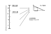
- FIG. 9 shows a state in which the D-phase comparison is performed by the VSL shift method with a single ramp signal having a length of 1 ⁇ 4 of the full-scale (FS) of the D-phase.
- the high-order determination period it is determined which voltage region the D-phase VSL level corresponds to, and in the subsequent D-phase period, the VSL level is shifted according to the determination result of the high-order bit, and the comparison is performed.
- the D-phase period can be shortened to a quarter by making the input signal to the device 171 fall within the voltage range of a quarter of the D-phase period.
- the pixel signal VSL expanded from 12 bits to 14 bits is AD-converted by the VSL shift method shown in FIG. 9, one kind of ramp signal for 12 bits (or P phase comparison) is used as the ramp signal.
- the upper determination period the upper 2 bits of the pixel signal VSL are determined. Then, based on which of the determination results of the upper bits is 00, 01, 10, 11, the pixel signal VSL of the D phase is shifted to the level of the P phase or the upper 2 bits “00”, and Perform correlated double sampling of the lower 12 bits compared to the ramp signal. Then, 2 bits acquired in the upper determination period can be concatenated with the obtained upper 12 bits of the lower 12 bits to be converted into 14-bit digital data.
- the D-phase period can be shortened to 1/4 as compared with the case where the comparison with VSL is performed on a full scale.
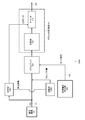
- FIG. 10 shows a schematic configuration example of a signal processing circuit 1000 for AD converting the pixel signal VSL by the VSL shift method.
- the signal processing circuit 1000 shown in the drawing is, with respect to the column AD conversion unit 161 shown in FIGS. 4 to 5, a determination unit 1001 that determines the upper bit of the pixel signal VSL, and a pixel signal VSL based on the determination result of the upper bit.
- the adjustment unit 1002 for adjusting the shift amount is added.
- the determination unit 1001 inputs the pixel signal VSL (before being input to the amplifier 202) transferred from the unit pixel 141 via the vertical signal line 121 during the D-phase settling, and determines the upper 2 bits thereof. To do.
- the determination result of the determination unit 1001 is written as the upper 2 bits of the counter 172 (described above) and is output to the adjustment unit 1002.
- the determination unit 1001 can be realized by a simple circuit using an inverter, a capacitor, and a switch element, for example, but the detailed configuration will be described later.
- the adjusting unit 1002 shifts the level of the pixel signal VSL by adding a DC offset voltage based on the determination result of the determining unit 1001 to the pixel signal VSL input to the column amplifier 160.
- the column amplifier 160 low-noise amplifies and inverts the level-shifted pixel signal VSL based on the upper bits, and outputs the pixel signal VSL to the column AD converter 161 in the subsequent stage.
- the reference voltage generation unit 102 generates a ramp signal in the ramp voltage range of 1 / N for the lower bit (excluding the upper bit) of the pixel signal VSL (where N is a positive integer). And) to the column AD converter 161.
- the comparator 181 compares the level-shifted pixel signal VSL input from the column amplifier 160 with the signal level of the ramp signal in the ramp voltage range that is 1 / N, and A signal indicating which signal level is higher is output from the output terminal VCO and supplied to the counter 172.
- the counter 172 counts the number of clocks of the clock signal from the start of counting until the comparison result of the comparator 171 is inverted (that is, the signal level of the output terminal VCO changes), and when the comparison result is inverted, the count is reached.
- the count value of is the AD conversion result of the lower bits of the pixel signal VSL.
- the upper bits of the AD conversion result of the lower bits are connected to the upper bits determined by the determination unit 1001 and output to the horizontal transfer unit 104 (not shown in FIG. 10) via the signal line 123.
- a specific operation of the signal processing circuit 1000 shown in FIG. 10 will be described by taking as an example the case where the pixel signal VSL expanded from 12 bits to 14 bits is AD-converted.
- the determination unit 1001 determines the upper 2 bits of the pixel signal VSL during the upper determination period during the D-phase settling. Then, the adjustment unit 1002 shifts the DC signal for shifting the D-phase pixel signal VSL to the level of the upper bit “00” based on which of the determination results of the upper two bits is 00, 01, 10, or 11.
- the offset voltage is added to the pixel signal VSL input to the column amplifier 160. Further, the reference voltage generation unit 102 generates a ramp signal in a ramp voltage range that is a quarter, for example, for 14 bits, and supplies the ramp signal to the comparator 181 in the column AD conversion unit 161.
- the comparator 181 compares the level-shifted pixel signal VSL with the signal level of the ramp signal in the pump voltage range that is 1 ⁇ 4, and outputs a signal indicating which signal level is larger from the output terminal VCO. And supplies it to the counter 172.
- the counter 172 counts the number of clocks of the clock signal from the start of counting until the comparison result of the comparator 171 is inverted, and sets the count value as the AD conversion result of the lower 12 bits of the pixel signal VSL. Then, the upper 2 bits determined by the determination unit 1001 can be connected to the upper 12 bits of the AD conversion result, and the 14-bit AD conversion result of the pixel signal VSL can be obtained.
- the upper bit is determined based on the voltage value of the pixel signal VSL at the time of D-phase settling, and the level shift amount of VSL is set, so that the lamp voltage range is reduced to 1 / N.
- the AD processing time can be shortened by pulling in the pixel signal VSL.
- FIG. 11 shows a specific circuit configuration example of the adjusting unit 1002 and the column amplifier 160 in the signal processing circuit 1000 shown in FIG.
- the column amplifier 160 is originally a low noise amplifier that amplifies VSL before inputting the pixel signal VSL transferred by the vertical signal line 121 to the column AD converter 161.
- the illustrated column amplifier 160 is a switched capacitor amplifier, and the column amplifier 160 includes a capacitor 1101 as C IN , an amplifier 1102, a capacitor 1103 as C FB , and a switch 1104, and two capacitors C IN and The gain for amplifying the input pixel signal VSL is determined by C FB .
- the pixel signal VSL transferred via the vertical signal line 121 is input to and accumulated in the first terminal of the capacitor 1101.
- a voltage signal having a voltage corresponding to the accumulated charge signal is output from the second terminal of the capacitor 1101 and input to the inverting input terminal of the amplifier 1102.
- the non-inverting input terminal of the amplifier 1102 is grounded. Then, the amplifier 1102 amplifies the voltage of the input voltage signal, and inverts and outputs the amplified voltage signal as the output of the column amplifier 160 to the column AD conversion unit 161 in the subsequent stage.
- the voltage signal inverted and output by the amplifier 1102 is input to the first terminal of the capacitor 1103 and accumulated.
- the voltage signal corresponding to the accumulated voltage signal is output from the second terminal of the capacitor 1103 to the amplifier 1102 as a feedback signal.
- the amplifier 1102 continues to output a voltage signal of a constant voltage according to the voltage of the feedback signal. That is, the amplifier 1102 continues to output the voltage signal of the voltage corresponding to the charge signal input to the column amplifier 160 to the column AD conversion unit 161 in the subsequent stage.
- the voltage signal output from the amplifier 1102 represents the magnitude of the pixel signal VSL generated by the corresponding unit pixel 141 of the pixel array 101, which is increased or decreased according to the ratio between the capacitance C IN of the capacitor 1101 and the capacitance C FB of the capacitor 1103.
- the capacitance C IN of the capacitor 1101 is 200 fF
- the capacitance C FB of the capacitor 1103 is variable among 200 fF, 100 fF, 50 fF, and 25 fF.
- the output terminal of the amplifier 1102 (which is also the first terminal of the capacitor 1103) is connected to the first terminal of the switch 1104, and the input terminal of the amplifier 1102 (which is also the second terminal of the capacitor 1103) is connected to the switch. It is connected to the second terminal of 1104. Then, the switch 1104 short-circuits or opens the first terminal and the second terminal of the capacitor 1103. When both terminals of the capacitor 1103 are short-circuited, the voltages of both terminals of the capacitor 1103 become the same voltage and are reset, and the amplification operation of the voltage signal by the amplifier 1102 is also reset.
- the signal processing circuit 1000 determines the upper bit of the VSL directly from the pixel signal VSL input via the vertical signal line 121, and the VSL of the VSL based on the determination result of the determination unit 1001.
- An adjustment unit 1002 for adjusting (shifting) the level is further provided.
- the determination unit 1001 and the adjustment unit 1002 are arranged outside the column amplifier 160 in FIG. 11, one or both of the functions of the determination unit 1001 and the adjustment unit 1002 can be installed in the column amplifier 160. is there.
- FIG. 11 shows a circuit configuration example of the adjusting unit 1002 in the case of shifting the VSL level by dividing the full scale of the D-phase VSL into four.
- the adjusting unit 1002 can be configured as in FIG. 11. It is also possible for those skilled in the art to configure the adjusting unit 1002 so as to divide the full scale of the D-phase VSL by a value other than a power of two.
- the determination unit 1001 determines the upper 2 bits of the pixel signal VSL (before being input to the amplifier 202) transferred via the vertical signal line 121.
- the determination result of the determination unit 1001 is written as the upper 2 bits of the counter 172 (described above) and is output to the adjustment unit 1001.
- the determination unit 1001 can be realized by a simple circuit using, for example, an inverter, a capacitor, and a switch element, but the detailed configuration thereof will be described later.
- the adjustment unit 1002 inputs the DC offset voltage ⁇ V SH based on the determination result of the upper 2 bits of the pixel signal VSL by the determination unit 1001 to the inverting input terminal of the amplifier 1102 (or the column amplifier 160) to output the upper 2 bits.
- the level of the pixel signal VSL is shifted by a shift amount according to the determination result.
- the adjustment unit 1002 is configured by a DA conversion circuit that generates a DC offset voltage.
- the adjustment unit 1002 has switches 1111 to 1113 (SW1, SW2, SW3), one end of which is commonly connected to the inverting input terminal of the amplifier 1102 and the other end of which is switched between the ground and the reference voltage signal V FSR. ) Are respectively connected to each other and have three capacitors 1114 to 1116 having the same capacitance C SH .
- the reference voltage signal V FSR is, for example, a 14-bit voltage signal corresponding to the full scale of the pixel signal VSL, and is supplied from the DA converter 1110.
- the capacities of the capacitors 1114 to 1116 do not have to be uniform, and the adjustment unit 1002 can be configured in a binary type by weighting each capacitor such as C, 2C, and 4C.
- the switches SW1, SW2, and SW3 denoted by reference numerals 1111 to 1113 are turned on / off based on the determination result of the upper 2 bits of the pixel signal VSL by the determination unit 1001, and the pixel signal VSL corresponding to the number of switches in the on state is changed.
- the level shift amount ⁇ V SH can be applied to the inverting input terminal of the amplifier 1102 (or the column amplifier 160).
- the shift amount ⁇ V SH is 1/4 ⁇ V FSR when only the switch SW1 is in the on state
- the shift amount ⁇ V SH is 1/2 ⁇ V FSR when the two switches SW1 and SW2 are in the on state.
- FIG. 12 illustrates the relationship between the determination result of the upper 2 bits of the pixel signal VSL, the on / off states of the switches SW1 to SW3, and the level shift amount ⁇ V SH of the pixel signal VSL.
- FIG. 13 shows an example in which the level of the pixel signal VSL is shifted by the adjustment unit 1002 when the upper bit determined by the determination unit 1001 is “11”.
- the pixel signal VSL is in a state before being input to the column amplifier 160, that is, before being inverted and output by the column amplifier 160.
- the level of the pixel signal VSL is shifted from “11” to “00”.
- whether the upper level of the pixel signal VSL is “10” or “01” is similarly shifted to the level “00” by the adjusting unit 1002.
- the column AD conversion unit 161 in the subsequent stage compares the lower 12 bits of the pixel signal VSL expanded to 14 bits with one kind of ramp signal for 12 bits (or for P phase comparison), and determines the comparison result. Correlated double sampling can be performed to obtain digital data. That is, the D-phase period or the AD processing time can be shortened to 1/4 by pulling the pixel signal VSL into the lamp voltage range of 1/4.
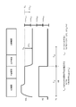
- FIG. 14 shows a circuit configuration example of the determination unit 1001. Further, FIG. 15 shows an operation timing chart of the determination unit 1001 in each processing phase of AD conversion.
- the determination unit 1001 performs a high-order determination using the pixel signal VSL before input to the column amplifier 160, and is composed of simple elements such as an inverter, a capacitor, and a switch element, as will be described later.
- the main feature is that it is short.
- the determination unit 1001 shown in FIG. 14 includes an inverter 1401, a first capacitor 1402 and a second capacitor 1403, a switch 1404, and a latch 1405.
- the pixel signal VSL transferred via the vertical signal line 121 is input to and accumulated in the first terminal of the first capacitor 1402. As a result, a voltage signal having a voltage corresponding to the accumulated charge signal is output from the second terminal of the first capacitor 1402.
- the DA converter 1406 generates a full-scale DC voltage of V-phase VSL as a reference voltage V FSR .
- This reference voltage V FSR is divided by a voltage dividing circuit composed of four resistance elements connected in series with the same resistance value, and four types of reference voltages 0/4 ⁇ V FSR and 1/4 with different voltage levels are obtained.
- ⁇ V FSR, 2/4 ⁇ V FSR, 3/4 ⁇ V FSR can be generated.
- the first terminal of the second capacitor 1403 has reference voltages 0/4 ⁇ V FSR , 1/4 ⁇ V FSR , and 2 / 4 ⁇ V FSR and 3/4 ⁇ V FSR are sequentially input.
- a voltage signal having a voltage corresponding to the accumulated charge signal is output from the second terminal of the second capacitor 1403.
- the second terminals of the first capacitor 1402 and the second capacitor 1403 are commonly connected to the inverter 1401.
- the voltage of the input terminal of the inverter 1401 is Va.
- the output of the inverter 1401 is input to the latch 1405.
- the calibration (T cal ) is performed using the auto-zero period and the P-phase period in which the level of the pixel signal VSL is constant. Specifically, the switch 1404 is turned on, the output of the inverter 1401 is short-circuited to the input of the inverter 1401, and the input / output offset is removed. This corrects the absolute deviation between the level V SP of the pixel signal VSL at the end of the P-phase period or the start of the D-phase period and the reference voltage V rP output from the second terminal of the second capacitor 1403.
- logical V th threshold value determined in the inverter 1401: VB
- the switch 1404 is turned off and the determination process of the upper bit of the pixel signal VSL is started.
- the level of the pixel signal VSL changes.
- the switches SW1, SW2, SW3, and SW4 are turned on in this order, so that the first terminal of the second capacitor 1403 receives the reference voltage as a reference voltage. 0/4 ⁇ V FSR, 1/4 ⁇ V FSR, 2/4 ⁇ V FSR, 3/4 ⁇ V FSR is inputted in order.
- the voltage signal output from the second terminal of the second capacitor 1403 changes.
- the pixel signal VSL also drops in the D-phase period, and the voltage signal output from the second terminal of the first capacitor 1402 also changes.
- the amount of change in the voltage level of the pixel signal VSL from the end of the P-phase period is ⁇ V S.
- the unit of the amount of change from the reference voltage V rP in the voltage level output from the second terminal of the second capacitor 1403 is ⁇ V ref .
- the input terminal voltage Va of the inverter 1401 changes in accordance with the changes ⁇ V S and ⁇ V ref of the voltage levels input to the first terminals of the first capacitor 1402 and the second capacitor 1403, respectively.
- Va in the determination period (T CM ) of the upper bits can be expressed by the following equation (1).
- n in the formula (1) is an integer of 0 to 3.
- the difference value between the voltage level change amount ⁇ V S of the pixel signal VSL and the reference voltage change amount ⁇ V ref is determined based on the logical threshold value (logical V th ): VB of the inverter 1401. It is composed. This makes it possible to absorb the deviation of the logical threshold value of each element of the inverter 1401 and accurately determine the upper bit of the D-phase pixel signal VSL.
- the switches SW1, SW2, and SW3 are sequentially turned on / off. On / off of each of the switches SW1, SW2, and SW3 is controlled by a 4-bit switch control signal.
- the switch control signal is "0000"
- the switch SW1 is on
- "0001” is the switch SW2 on
- "0011” is the switch SW3 on
- "0111” is the switch SW3 on.
- the 4-bit switch control signal is also input to the latch 1405.
- the switches SW1, SW2, SW3, and SW4 are sequentially switched on and off in the determination period (T CM ) of the upper bit, the change amount ⁇ V S of the voltage level of the pixel signal VSL and the change from the reference voltage V rP.
- the output of the inverter 1401 changes according to the amount ⁇ V ref ⁇ n.
- the latch 1405 temporarily holds the 4-bit switch control signal input when the output of the inverter 1401 is inverted as a determination result.
- 16 and 17 show examples of determination results of the inverter 1401 as operation examples of the determination unit 1001.
- the change amount ⁇ V S of the voltage level of the pixel signal VSL is small, and the output of the inverter 1401 is output regardless of the voltage level ⁇ V ref ⁇ n output from the second terminal of the second capacitor 1403. Is not inverted, the determination result by the determination unit 1001 is “0000”.
- the amount of change ⁇ V S of the voltage level of the pixel signal VSL is rather large, and the output of the inverter 1401 is at the voltage level ⁇ V ref ⁇ 3 output from the second terminal of the second capacitor 1403. Since it is inverted, the determination result by the determination unit 1001 is “0011”.
- the determination result by the determination unit 1001 is “0010”.
- the determination result by the determination unit 1001 is “0111”.
- the 4-bit determination result by the inverter 1401 corresponds to the on / off control of the switches SW1, SW2, and SW3. Then, the determination result of the upper 2 bits of the pixel signal VSL by the determination unit 1001 is acquired by using 3 bits of the determination result of 4 bits by the inverter 1401.
- FIG. 18 shows the relationship between the 4-bit determination result of the inverter 1401 and the high-order 2 bits output from the determination unit 1001.
- the determination result of the determination unit 1001 is written as the upper 2 bits of the counter 172 (described above) and is output to the adjustment unit 1002.
- the level of the VSL of the D phase is determined in N steps, the level of the VSL of the D phase is shifted based on the determination result, and the input to the comparator 171 is performed.
- the D phase period in the AD conversion process can be shortened to 1 / N.
- the 14-bit AD conversion processing time can be shortened by 60%.
- the signal processing circuit 1000 is configured to determine the upper bit of the pixel signal VSL during the D-phase settling and adjust the shift amount of the pixel signal VSL input to the column amplifier 160 based on the determination result of the upper bit. ..
- the circuits of the determination unit 1001 that determines the higher-order bits of the pixel signal VSL and the adjustment unit 1002 that adjusts the shift amount of the pixel signal VSL can be implemented in the circuit of the column amplifier 160 for the purpose of low noise amplification.
- the determination unit 1001 is configured to perform high-order determination using the pixel signal VSL before input to the column amplifier 160 (see FIGS. 10 and 11), and includes simple elements such as an inverter, a capacitor, and a switch element. Therefore (see FIG. 14), the main feature is that the determination time is short.
- the VSL shift method is implemented using the signal processing circuit 1000, the relationship between the AD conversion unit 161 and the ramp signal is the same as the conventional AD conversion processing (without VSL shift). Therefore, there are no problems such as load capacity fluctuations and circuit scales that occur in the multi-lamp method, and calibration for every 1H is also unnecessary.
- the implied characteristic at the time of a small signal (when the light is shielded or at the black level) that most affects the image quality is similar to the conventional AD conversion processing (without VSL shift), and is a good characteristic. It is possible to shorten the AD conversion processing time while maintaining the above.
- FIG. 19 shows a configuration example of an imaging device 1900 configured by applying the technology disclosed in this specification.
- the imaging device 1900 corresponds to, for example, a digital still camera or a digital video camera.
- the illustrated image pickup apparatus 1900 includes an optical system 1901, an image sensor 1902, a signal processing unit 1903, a recording / reproducing unit 1904, a recording unit 1905, and a control unit 1906.
- the optical system 1901 includes a mechanical shutter, a lens, a diaphragm mechanism, and the like.
- the lens collects the reflected light from the subject and makes it enter the pixel area of the image sensor 1902 through the diaphragm mechanism.
- the image sensor 1902 has the configuration shown in FIG. 1, but in the AD conversion unit 103, it is configured by a column amplifier 160 and a column AD conversion unit 161 to which the signal processing circuit 1000 shown in FIG. 10 is applied. And The image sensor 1902 generates an image signal corresponding to the light from the optical system 1901, performs digital conversion, and outputs the image signal to the signal processing unit 1903.
- the signal processing unit 1903 performs digital processing such as digital gain processing and gamma processing on the digital image signal output from the image sensor 1902 to generate a signal suitable for recording in the recording unit 1905.
- the recording / reproducing unit 1904 records the signal supplied from the signal processing unit 1904 in the recording unit 1905. Further, the recording / reproducing unit 1904 reproduces the signal recorded in the recording unit 1905 and displays it on a display device (not shown) that is equipped with the imaging device 1900 or is externally connected.
- the recording unit 1905 is composed of a recording medium such as a hard disk or a semiconductor memory, and the recording / reproducing unit 1904 records and reproduces signals.
- the control unit 1906 is composed of, for example, a microprocessor, and controls the operation of each unit in the imaging apparatus 1900 in a centralized manner. For example, the control unit 1906 comprehensively controls the operation of each unit in the image capturing apparatus 1900 according to an instruction from the user input via a user interface (not shown) included in the image capturing apparatus 1900. Further, the control unit 1906 drives and controls the mechanical shutter and the diaphragm mechanism in the optical system 1901 to realize automatic exposure processing and the like.
- FIG. 20 shows a configuration example of an information processing device 2000 equipped with an image sensor configured by applying the technology disclosed in this specification.
- the information processing device 2000 corresponds to, for example, a smartphone, a tablet, or another type of information terminal, but with respect to the control unit 2010, a display unit 2020, a voice processing unit 2030, a communication unit 2040, a storage unit 2050, an imaging unit 2060. , The sensor unit 2070, etc. are connected.
- the control unit 2010 includes a CPU 2011, a ROM (Read Only Memory) 2012, a RAM (Random Access Memory) 20613, and the like.
- the ROM 2012 stores program codes executed by the CPU 2011, information essential to the information processing apparatus 2000, and the like.
- the CPU 2011 loads the program code from the ROM 2012 or the storage unit 2050 into the RAM 2013 and executes it.
- Examples of the program executed by the CPU 2011 include an operating system (OS) such as Android and iOS, and various application programs operating under the execution environment provided by the OS.
- OS operating system
- iOS various application programs operating under the execution environment provided by the OS.
- the display unit 2020 includes a display panel 2021 including a liquid crystal element, an organic EL (Electro Luminescence) element, and the like, and a transparent touch panel 2023 attached to the upper surface of the display panel 2021.
- the display panel 2021 is connected to the control unit 2010 via the display interface 2022, and displays and outputs the image information generated by the control unit 610.
- the touch panel 2023 is connected to the control unit 2010 via the touch interface 2024, and outputs coordinate information, which the user operates on the display panel 2021 with a fingertip, to the control unit 2010.
- a touch operation by the user (tap, long press, flick, swipe, etc.) is detected based on the input coordinate information, and a process corresponding to the user operation is activated.
- the audio processing unit 2030 includes an audio output unit 2031 such as a speaker, an audio input unit 2032 such as a microphone, and an audio codec (CODEC) 2033 that encodes and decodes input and output audio signals.
- the audio processing unit 2030 may further include an audio output terminal 2034 for outputting an audio signal to headphones (not shown).
- the communication unit 2040 performs communication processing of information between an application executed by the control unit 2010 and an external device (not shown). Examples of the external device mentioned here include an information terminal handled by another user, a server existing on the Internet, and the like.
- the communication unit 2040 is equipped with physical layer modules such as Wi-Fi (registered trademark), NFC (Near Field Communication), and Bluetooth (registered trademark) communication depending on the communication medium used, and via the physical layer module. Modulation / demodulation processing and coding / decoding processing of transmitted / received communication signals are performed.
- the storage unit 2050 is composed of a large-capacity storage device such as SSD (Solid State Drive) or HDD (Hard Disc Drive). For example, application programs and contents downloaded via the communication unit 2040, image data such as still images and moving images captured by the image capturing unit 2060, and the like are stored in the storage unit 2050.
- SSD Solid State Drive
- HDD Hard Disc Drive
- the image capturing unit 2060 corresponds to the image capturing apparatus 1900 shown in FIG. 19 and applies the technology disclosed in this specification.
- the imaging unit 2060 outputs the generated image data to the control unit 2010 via a camera interface (not shown).
- the sensor unit 2070 is a GPS (Global Positioning System) sensor for acquiring the position information of the information processing apparatus 2000, a gyro sensor for detecting the posture or acting force of the information processing apparatus 2000 main body, and an acceleration sensor. Etc. are included.
- GPS Global Positioning System
- the technology disclosed in this specification can be suitably applied mainly to a column AD conversion unit of an image sensor such as CMOS or CCD.
- the technique disclosed in this specification can be similarly applied to an AD conversion circuit that is required to have a simple configuration.
- the image sensor to which the technology disclosed in this specification is applied can be widely used for digital still cameras, digital video cameras, vehicle-mounted cameras, and various information terminals such as smartphones and tablets.
- An amplifier that amplifies an analog signal
- a determination unit that determines the higher-order bits of the analog signal
- An adjustment unit that adjusts the level of the analog signal input to the amplifier based on the determination result of the determination unit
- a single-slope AD converter that AD-converts the lower bits of the analog signal using the level-adjusted output signal
- a signal processing device comprising: (2) The determination unit is configured to determine a higher-order bit of the analog signal before being input to the amplifier.
- the signal processing device according to (1) above.
- the determination unit includes an inverter, a capacitor, and a switch element, The signal processing device according to any one of (1) and (2) above.
- the determination unit includes a first capacitor to which the analog signal is input to a first terminal and a second capacitor to which a reference signal is input to the first terminal, and the inverter includes the first capacitor.
- the second terminals of the first and second capacitors are input, and the switching element shorts the output of the inverter to the input during the auto-zero period,
- the signal processing device according to (3) above.
- the determination unit determines a higher-order bit of the analog signal during D-phase settling in AD conversion of the analog signal, The signal processing device according to any one of (1) to (4) above.
- a high-order bit determined by the determination unit and a low-order bit output from the AD conversion unit are connected to output a digital signal obtained by AD-converting the analog signal.
- the signal processing device according to any one of (1) to (5) above.
- the amplifier is composed of a switched capacitor amplifier, The signal processing device according to any one of (1) to (6) above.
- At least one of the determination unit and the adjustment unit is mounted in the circuit of the amplifier.
- the signal processing device according to (7) above.
- the analog signal is a pixel signal output from a pixel,
- the signal processing device according to any one of (1) to (8) above.
- the amplifier is a column amplifier, the AD converter is a column AD converter, and the signal processing apparatus according to any one of (1) to (9) is used.
- Image sensor (11) An imaging device including the image sensor according to (10). (12) An information processing device equipped with the imaging device according to (11).
- Control unit 2000 ... Information processing device, 2010 ... Control unit, 2020 ... Display unit 2021 ... Display panel, 2022 ... Display interface 2023 ... Touch panel, 2024 ... Touch interface 2030 ... Voice processing unit, 2031 ... Voice output unit 2032 ... Audio input unit, 2033 ... Audio codec 2034 ... Audio output terminal, 2040 ... Communication unit, 2050 ... Storage unit 2060 ... Imaging unit, 2070 ... Sensor unit
Landscapes
- Engineering & Computer Science (AREA)
- Theoretical Computer Science (AREA)
- Multimedia (AREA)
- Signal Processing (AREA)
- Transforming Light Signals Into Electric Signals (AREA)
- Analogue/Digital Conversion (AREA)
Abstract
L'invention concerne un dispositif de traitement de signal pour réaliser un type à pente unique de conversion A/N. Le dispositif de traitement de signal comprend : un amplificateur qui amplifie un signal analogique ; une unité de détermination qui détermine des bits d'ordre supérieur du signal analogique ; une unité de réglage qui, sur la base d'un résultat de détermination de l'unité de détermination, ajuste le niveau du signal analogique à entrer dans l'amplificateur ; et un type à pente unique d'une unité de conversion A/N qui convertit en A/N des bits d'ordre inférieur du signal analogique en utilisant le signal de sortie à niveau ajusté. L'unité de détermination qui est constituée d'un onduleur, un condensateur et un élément de commutation détermine les bits d'ordre supérieur du signal analogique qui doit être entré dans l'amplificateur.
Applications Claiming Priority (2)
| Application Number | Priority Date | Filing Date | Title |
|---|---|---|---|
| JP2018207130A JP2020072435A (ja) | 2018-11-02 | 2018-11-02 | 信号処理装置、イメージセンサ、撮像装置、並びに情報処理装置 |
| JP2018-207130 | 2018-11-02 |
Publications (1)
| Publication Number | Publication Date |
|---|---|
| WO2020090166A1 true WO2020090166A1 (fr) | 2020-05-07 |
Family
ID=70462610
Family Applications (1)
| Application Number | Title | Priority Date | Filing Date |
|---|---|---|---|
| PCT/JP2019/029085 Ceased WO2020090166A1 (fr) | 2018-11-02 | 2019-07-24 | Dispositif de traitement de signal, capteur d'image, dispositif de capture d'image et dispositif de traitement d'informations |
Country Status (2)
| Country | Link |
|---|---|
| JP (1) | JP2020072435A (fr) |
| WO (1) | WO2020090166A1 (fr) |
Cited By (2)
| Publication number | Priority date | Publication date | Assignee | Title |
|---|---|---|---|---|
| JP2022161104A (ja) * | 2021-04-08 | 2022-10-21 | キヤノン株式会社 | 撮像装置 |
| JP2024096911A (ja) * | 2020-07-30 | 2024-07-17 | 富士フイルム株式会社 | 手ブレ補正装置 |
Families Citing this family (1)
| Publication number | Priority date | Publication date | Assignee | Title |
|---|---|---|---|---|
| JP2022117164A (ja) * | 2021-01-29 | 2022-08-10 | ローム株式会社 | 電圧コンパレータ回路、電源管理回路、電子機器 |
Citations (7)
| Publication number | Priority date | Publication date | Assignee | Title |
|---|---|---|---|---|
| JPH0851364A (ja) * | 1994-08-09 | 1996-02-20 | Kawasaki Steel Corp | 逐次比較a/d変換器 |
| JP2010503253A (ja) * | 2006-08-31 | 2010-01-28 | コーニンクレッカ フィリップス エレクトロニクス エヌ ヴィ | 単一スロープ型アナログ‐デジタル・コンバータ |
| JP2011066773A (ja) * | 2009-09-18 | 2011-03-31 | Sanyo Electric Co Ltd | アナログデジタル変換回路およびそれを搭載した撮像装置 |
| JP2011239068A (ja) * | 2010-05-07 | 2011-11-24 | Toshiba Corp | 固体撮像装置 |
| US20120050082A1 (en) * | 2010-08-30 | 2012-03-01 | Broadcom Corporation | Composite analog-to-digital converter |
| WO2015141490A1 (fr) * | 2014-03-20 | 2015-09-24 | ソニー株式会社 | Élément de capture d'image, procédé de commande et dispositif de capture d'image |
| JP2018078350A (ja) * | 2015-03-19 | 2018-05-17 | パナソニックIpマネジメント株式会社 | Ad変換器、イメージセンサ、および撮像装置 |
-
2018
- 2018-11-02 JP JP2018207130A patent/JP2020072435A/ja active Pending
-
2019
- 2019-07-24 WO PCT/JP2019/029085 patent/WO2020090166A1/fr not_active Ceased
Patent Citations (7)
| Publication number | Priority date | Publication date | Assignee | Title |
|---|---|---|---|---|
| JPH0851364A (ja) * | 1994-08-09 | 1996-02-20 | Kawasaki Steel Corp | 逐次比較a/d変換器 |
| JP2010503253A (ja) * | 2006-08-31 | 2010-01-28 | コーニンクレッカ フィリップス エレクトロニクス エヌ ヴィ | 単一スロープ型アナログ‐デジタル・コンバータ |
| JP2011066773A (ja) * | 2009-09-18 | 2011-03-31 | Sanyo Electric Co Ltd | アナログデジタル変換回路およびそれを搭載した撮像装置 |
| JP2011239068A (ja) * | 2010-05-07 | 2011-11-24 | Toshiba Corp | 固体撮像装置 |
| US20120050082A1 (en) * | 2010-08-30 | 2012-03-01 | Broadcom Corporation | Composite analog-to-digital converter |
| WO2015141490A1 (fr) * | 2014-03-20 | 2015-09-24 | ソニー株式会社 | Élément de capture d'image, procédé de commande et dispositif de capture d'image |
| JP2018078350A (ja) * | 2015-03-19 | 2018-05-17 | パナソニックIpマネジメント株式会社 | Ad変換器、イメージセンサ、および撮像装置 |
Cited By (5)
| Publication number | Priority date | Publication date | Assignee | Title |
|---|---|---|---|---|
| JP2024096911A (ja) * | 2020-07-30 | 2024-07-17 | 富士フイルム株式会社 | 手ブレ補正装置 |
| JP7712420B2 (ja) | 2020-07-30 | 2025-07-23 | 富士フイルム株式会社 | 手ブレ補正装置 |
| US12585173B2 (en) | 2020-07-30 | 2026-03-24 | Fujifilm Corporation | Lens barrel |
| JP2022161104A (ja) * | 2021-04-08 | 2022-10-21 | キヤノン株式会社 | 撮像装置 |
| JP7735071B2 (ja) | 2021-04-08 | 2025-09-08 | キヤノン株式会社 | 撮像装置 |
Also Published As
| Publication number | Publication date |
|---|---|
| JP2020072435A (ja) | 2020-05-07 |
Similar Documents
| Publication | Publication Date | Title |
|---|---|---|
| US8427565B2 (en) | Solid-state imaging apparatus and imaging system | |
| US8854244B2 (en) | Imagers with improved analog-to-digital converters | |
| US10609318B2 (en) | Imaging device, driving method, and electronic apparatus | |
| US10104326B2 (en) | Imaging apparatus including analog-to-digital conversion circuits to convert analog signals into digital signals, imaging system including analog-to-digital conversion circuits to convert analog signals into digital signals, and imaging apparatus driving method | |
| US7567280B2 (en) | Solid-state imaging device, analogue-digital converting method in solid-state imaging device and imaging apparatus | |
| US8269872B2 (en) | Analog-to-digital converter, analog-to-digital converting method, solid-state image pickup device, and camera system | |
| US8111312B2 (en) | Solid-state imaging device, method of driving the same, and camera | |
| US8379122B2 (en) | Solid-state image-pickup device, camera system, and method for driving same | |
| US6885331B2 (en) | Ramp generation with capacitors | |
| US9848150B2 (en) | Image pickup apparatus comprising A/D converter with offset and gain correction based on amplitude of input signal | |
| US8963759B2 (en) | Imaging systems with per-column analog-to-digital converter non-linearity correction capabilities | |
| TW200833097A (en) | Solid state imaging device, drive method of solid state imaging device, and imaging device | |
| US20080169955A1 (en) | Ad conversion method, apparatus thereof, solid-state imaging device, driving method thereof, and imaging apparatus | |
| JP2018082261A (ja) | 撮像素子 | |
| JP2013175936A (ja) | 半導体装置、及び、撮像装置 | |
| US10574917B2 (en) | Pixel output level control device and CMOS image sensor using the same | |
| JP2013251874A (ja) | 撮像装置、撮像装置の駆動方法、撮像システム、撮像システムの駆動方法 | |
| JP2018125845A (ja) | 撮像素子 | |
| WO2020090166A1 (fr) | Dispositif de traitement de signal, capteur d'image, dispositif de capture d'image et dispositif de traitement d'informations | |
| US8963758B2 (en) | Image sensor and image capturing apparatus | |
| US11558575B2 (en) | Analog-to-digital converter having reference signal, image sensor, and image capturing apparatus | |
| US9113101B2 (en) | Image sensor and image capturing system | |
| JP6112871B2 (ja) | 撮像素子及び撮像装置 | |
| JP6598837B2 (ja) | 撮像装置、撮像システム | |
| JP6242467B2 (ja) | 撮像装置、撮像システム |
Legal Events
| Date | Code | Title | Description |
|---|---|---|---|
| 121 | Ep: the epo has been informed by wipo that ep was designated in this application |
Ref document number: 19878400 Country of ref document: EP Kind code of ref document: A1 |
|
| NENP | Non-entry into the national phase |
Ref country code: DE |
|
| 122 | Ep: pct application non-entry in european phase |
Ref document number: 19878400 Country of ref document: EP Kind code of ref document: A1 |