WO2020090587A1 - Vanne de régulation - Google Patents
Vanne de régulation Download PDFInfo
- Publication number
- WO2020090587A1 WO2020090587A1 PCT/JP2019/041544 JP2019041544W WO2020090587A1 WO 2020090587 A1 WO2020090587 A1 WO 2020090587A1 JP 2019041544 W JP2019041544 W JP 2019041544W WO 2020090587 A1 WO2020090587 A1 WO 2020090587A1
- Authority
- WO
- WIPO (PCT)
- Prior art keywords
- control valve
- cap
- pilot pressure
- spool
- housing
- Prior art date
- Legal status (The legal status is an assumption and is not a legal conclusion. Google has not performed a legal analysis and makes no representation as to the accuracy of the status listed.)
- Ceased
Links
Images


Classifications
-
- F—MECHANICAL ENGINEERING; LIGHTING; HEATING; WEAPONS; BLASTING
- F15—FLUID-PRESSURE ACTUATORS; HYDRAULICS OR PNEUMATICS IN GENERAL
- F15B—SYSTEMS ACTING BY MEANS OF FLUIDS IN GENERAL; FLUID-PRESSURE ACTUATORS, e.g. SERVOMOTORS; DETAILS OF FLUID-PRESSURE SYSTEMS, NOT OTHERWISE PROVIDED FOR
- F15B11/00—Servomotor systems without provision for follow-up action; Circuits therefor
- F15B11/08—Servomotor systems without provision for follow-up action; Circuits therefor with only one servomotor
-
- F—MECHANICAL ENGINEERING; LIGHTING; HEATING; WEAPONS; BLASTING
- F16—ENGINEERING ELEMENTS AND UNITS; GENERAL MEASURES FOR PRODUCING AND MAINTAINING EFFECTIVE FUNCTIONING OF MACHINES OR INSTALLATIONS; THERMAL INSULATION IN GENERAL
- F16K—VALVES; TAPS; COCKS; ACTUATING-FLOATS; DEVICES FOR VENTING OR AERATING
- F16K3/00—Gate valves or sliding valves, i.e. cut-off apparatus with closing members having a sliding movement along the seat for opening and closing
- F16K3/22—Gate valves or sliding valves, i.e. cut-off apparatus with closing members having a sliding movement along the seat for opening and closing with sealing faces shaped as surfaces of solids of revolution
- F16K3/24—Gate valves or sliding valves, i.e. cut-off apparatus with closing members having a sliding movement along the seat for opening and closing with sealing faces shaped as surfaces of solids of revolution with cylindrical valve members
- F16K3/26—Gate valves or sliding valves, i.e. cut-off apparatus with closing members having a sliding movement along the seat for opening and closing with sealing faces shaped as surfaces of solids of revolution with cylindrical valve members with fluid passages in the valve member
-
- F—MECHANICAL ENGINEERING; LIGHTING; HEATING; WEAPONS; BLASTING
- F16—ENGINEERING ELEMENTS AND UNITS; GENERAL MEASURES FOR PRODUCING AND MAINTAINING EFFECTIVE FUNCTIONING OF MACHINES OR INSTALLATIONS; THERMAL INSULATION IN GENERAL
- F16K—VALVES; TAPS; COCKS; ACTUATING-FLOATS; DEVICES FOR VENTING OR AERATING
- F16K31/00—Actuating devices; Operating means; Releasing devices
- F16K31/12—Actuating devices; Operating means; Releasing devices actuated by fluid
- F16K31/14—Actuating devices; Operating means; Releasing devices actuated by fluid for mounting on, or in combination with, hand-actuated valves
Definitions
- the present invention relates to a control valve that controls the flow of working fluid.
- a control valve used in a fluid pressure control device a manual control valve whose position is switched by a manual operation by an operator is known (for example, see JP1994-227789A).
- a valve body is housed in a housing hole that opens at the end of the housing, and a cap is provided so as to close the opening of the housing hole.
- a spring for urging the valve element toward one side is provided inside the cap. The position of the control valve is switched by manually moving the valve body against the biasing force of the spring.
- the present invention has an object to provide a manual switching type control valve which can be operated by a signal from the outside.
- a control valve for controlling a flow of a working fluid
- the valve including a housing, a housing hole formed in the housing and opening to an end surface of the housing, and a valve slidably inserted into the housing hole.
- Body a cap that seals the opening of the accommodation hole, a biasing member that biases the valve body in one direction, and a cap that is provided on the cap and moves the valve body manually against the biasing force of the biasing member.
- Switching portion a pilot pressure chamber formed inside the cap for guiding a pilot pressure for urging the valve body against the urging force of the urging member, and a pilot formed for the cap to guide the pilot pressure to the pilot pressure chamber.
- a port a drain passage for releasing the pressure of the pilot pressure chamber, and a throttle portion provided in the drain passage for imparting resistance to the flow of the working fluid passing therethrough.
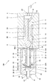
- FIG. 1 is a cross-sectional view of a control valve according to an embodiment of the present invention, showing a state in a communication position.
- FIG. 2 is a cross-sectional view of the control valve according to the embodiment of the present invention, and is a view showing a state in the shutoff position.
- FIG. 3 is a cross-sectional view of the control valve according to the embodiment of the present invention, showing a state in which the control valve is switched to the cutoff position by the pilot pressure.
- control valve 100 according to the embodiment of the present invention will be described with reference to the drawings.
- the control valve 100 is used for a fluid pressure control device (not shown) mounted on a construction machine such as a hydraulic excavator, and is a working fluid guided from a fluid pressure supply source (not shown) to a fluid pressure device (not shown). It controls the flow of.
- a fluid pressure control device mounted on a construction machine such as a hydraulic excavator
- a working fluid guided from a fluid pressure supply source (not shown) to a fluid pressure device (not shown). It controls the flow of.
- the working fluid is not limited to working oil, and may be other non-compressible fluid or compressible fluid.
- the control valve 100 is a two-position control valve that can be switched between two positions by moving the spool 10.
- the control valve 100 includes a housing 1, a housing hole 1A formed in the housing 1 and opening to an end surface 1B of the housing 1, and a spool as a valve body slidably inserted into the housing hole 1A. 10, a cap 30 for sealing the opening of the accommodation hole 1A, a spring 35 as a biasing member provided in the cap 30 for biasing the spool 10 in one direction, and a spring provided by the cap 30 and manually operated.
- a pilot port 55 that is formed in the cap 30 and guides pilot pressure to the pilot pressure chamber 50, and a spring 35 that is provided in the cap 30 End is seated comprises a spring seat 60, 65 as a pair of seat members which relatively move with the expansion and contraction of the spring 35.
- an inflow passage 2A and an outflow passage 2B through which hydraulic oil flows are formed side by side in the axial direction.
- the inflow passage 2A communicates with the accommodation hole 1A and communicates with a fluid pressure supply source via a pipe or the like (not shown).
- the outflow passage 2B communicates with the accommodation hole 1A and communicates with a hydraulic device or the like via a pipe or the like not shown.
- a tank port 2C communicating with the tank T is formed at the bottom of the accommodation hole 1A. The tank port 2C guides the hydraulic oil, which is introduced between the bottom of the accommodation hole 1A and the end of the spool 10, to the tank T.
- the spool 10 has a main body 11 that is in sliding contact with the inner peripheral surface of the accommodation hole 1A, and a support 20 that is attached to one end (the left end in the figure) of the main body 11.
- the main body portion 11 is formed to have a smaller diameter than the first land portion 12 and the second land portion 13 and the first land portion 12 and the second land portion 13 that slide along the inner peripheral surface of the accommodation hole 1A. And a connecting portion 14 that connects the portion 12 and the second land portion 13.
- the connecting portion 14 is formed to have a smaller diameter than the first land portion 12 and the second land portion 13, and forms an annular fluid chamber 5 with the inner peripheral surface of the accommodation hole 1A.
- the fluid chamber 5 communicates with the inflow passage 2A and the outflow passage 2B as the spool 10 moves, and guides the hydraulic oil that has passed through the inflow passage 2A to the outflow passage 2B.
- a first small-diameter portion 15 having an outer diameter smaller than the inner diameter of the accommodation hole 1A is provided at one end of the main body portion 11, and a first small-diameter portion is provided at one end side of the first small-diameter portion 15 (support portion 20 side, left side in the drawing).
- a second small diameter portion 16 having an outer diameter smaller than that of the portion 15 is formed.
- An annular space 6 is formed between the first small diameter portion 15 and the accommodation hole 1A.
- the support portion 20 is housed inside the cap 30.
- the support portion 20 has a shaft portion 21 attached to the second small diameter portion 16 at one end of the main body portion 11 by screw fastening, and a head portion 22 having an outer diameter larger than that of the shaft portion 21. That is, the support portion 20 is detachably attached to the main body portion 11.
- the shaft portion 21 has an outer diameter substantially the same as the second small diameter portion 16 of the main body portion 11 and is coaxially attached to the second small diameter portion 16.
- a slit 23 extending in the radial direction is formed on the end surface of the head portion 22.
- the cap 30 has a large-diameter hole 31 that communicates with the accommodation hole 1A and allows the spool 10 to enter, a small-diameter hole 32 that communicates with the large-diameter hole 31 and has an inner diameter smaller than that of the large-diameter hole 31, and communicates with the large-diameter hole 31. And a pilot port 55 that operates.
- the small diameter hole 32 and the large diameter hole 31 form a pilot pressure chamber 50.
- the head portion 22 of the support portion 20 enters the small diameter hole 32.
- the spring 35 is provided on the outer periphery of the shaft portion 21 of the support portion 20, and both ends thereof are supported by the pair of spring seats 60 and 65.
- One spring seat 60 is seated on the step surface 22A between the shaft part 21 and the head part 22, and the other spring seat 65 is seated on the end surface 1B of the housing 1 to which the cap 30 is attached.
- the spring 35 is interposed between the pair of spring seats 60 and 65 in a compressed state. Therefore, the spring 35 exerts an urging force that moves the spool 10 in a direction (left direction in the drawing) that connects the inflow passage 2A and the outflow passage 2B.
- the pair of spring seats 60 and 65 are formed in the same shape.
- One of the spring seats 60 has a disc-shaped flange portion 61 that comes into contact with a step surface 31A between the large diameter hole 31 and the small diameter hole 32 of the cap 30, and a shaft extending from the flange portion 61 toward the other spring seat 65.
- a cylindrical boss portion 62 extending in the direction.
- the inner diameter of the flange portion 61 is formed smaller than the outer diameter of the head portion 22.
- a slit 61A extending in the radial direction is formed on the end surface of the flange portion 61 that contacts the step surface 31A between the large diameter hole 31 and the small diameter hole 32.
- the other spring seat 65 has a disc-shaped flange portion 66 that contacts the end surface 1B of the housing 1, and a cylindrical boss portion 67 that extends axially from the flange portion 66 toward the one spring seat 60. ..
- a slit 66 ⁇ / b> A extending in the radial direction is formed on the end surface of the flange portion 66 that contacts the end surface 1 ⁇ / b> B of the housing 1.
- the switching portion 40 is screwed into the screw hole 33 formed in the cap 30, and regulates a change in the screwing position of the switching bolt 41 with respect to the screw hole 33 and the switching bolt 41 that moves forward and backward with respect to the spool 10 by a manual operation. And a restriction nut 45.
- the screw hole 33 is formed in the cap 30 so as to communicate with the pilot pressure chamber 50 (small diameter hole 32).
- the switching bolt 41 has a screw portion 42 that is screwed into the screw hole 33, a contact portion 43 that axially contacts the head portion 22 of the spool 10, and an operation portion 44 that is operated by an operator.
- the contact portion 43 is housed in the small diameter hole 32.
- a part of the screw portion 42 protrudes to the outside of the cap 30, and an operating portion 44 is provided at the end of the protruding screw portion 42.
- the screwing position of the screw portion 42 with respect to the screw hole 33 is adjusted by the operator gripping and rotating the operation portion 44.
- the restriction nut 45 is screwed onto the screw portion 42 exposed on the outside of the cap 30.
- the restriction nut 45 screwed to the switching bolt 41 is tightened to the cap 30, the change of the screwing position of the switching bolt 41 with respect to the screw hole 33 of the cap 30 is restricted.
- the regulation nut 45 by loosening the regulation nut 45 to create a gap between the regulation nut 45 and the cap 30, the screwing position of the switching bolt 41 with respect to the screw hole 33 of the cap 30 can be adjusted, and the switching bolt 41 is The spool 10 can be moved back and forth.
- the control valve 100 further includes a drain passage 70 that allows the pressure in the pilot pressure chamber 50 to escape, and a throttle portion that is provided in the drain passage 70 and that imparts resistance to the flow of hydraulic oil passing therethrough.
- the drain passage 70 is formed inside the spool 10.
- the drain passage 70 passes through the axial center of the main body portion 11 of the spool 10 and is in continuous communication with the tank port 2C formed in the housing 1, and the annular space 6 on the outer periphery of the first small diameter portion 15 and the axial direction.
- a throttle passage 72 which is a throttle portion that communicates the passage 71 and has a larger flow passage resistance than the axial passage 71.
- the axial passage 71 opens at the end surface of the main body 11 of the spool 10.
- the axial passage 71 always communicates with the tank port 2C through a space (a part of the accommodation hole 1A) between the main body 11 and the bottom of the accommodation hole 1A.
- pilot pressure chamber 50 always communicates with the annular space 6 through the slit 66A of the flange portion 66 of the other spring seat 65. Therefore, the pilot pressure chamber 50 is always in communication with the tank T through the drain passage 70 and the tank port 2C regardless of the position of the control valve 100 (position of the spool 10).
- the position of the control valve 100 is switched by adjusting the screwing position of the switching bolt 41 of the switching unit 40.
- a state in which the inflow passage 2A and the outflow passage 2B communicate with each other is referred to as a "communication position”
- a state in which the inflow passage 2A and the outflow passage 2B communicate with each other is referred to as a "blocking position”.
- the spool 10 moves against the biasing force of the spring 35 until the boss portions 62 and 67 of the pair of spring seats 60 and 65 come into contact with each other.
- the abutment of the pair of spring seats 60, 65 restricts the movement of the spool 10 against the biasing force of the spring 35.
- the restriction nut 45 is loosened and the switching bolt 41 is rotated so as to be separated from the spool 10.
- the spool 10 receives the biasing force of the spring 35 and moves together with the one spring seat 60 so as to follow the switching bolt 41 separated from the spool 10.
- the spool 10 moves under the biasing force of the spring 35 until the spring seat 60 contacts the step surface 31A between the large diameter hole 31 and the small diameter hole 32.
- the inflow passage 2A and the outflow passage 2B communicate with each other through the fluid chamber 5, as shown in FIG.
- the regulation nut 45 is tightened to regulate the change in the screwing position of the switching bolt 41. In this way, the control valve 100 is switched to the communication position.
- a fluid pressure control device incorporating a control valve that is switched by a manual operation may be inspected at the time of shipment by an automatic inspection line in the inspection process at the time of manufacture.
- the operation check of the control valve needs to be performed manually by an operator in addition to the inspection by the automatic inspection line.
- the space around the switching portion of the control valve is small, it becomes difficult to operate the switching portion, and a lot of man-hours are required for the step of checking the operation of the control valve.
- the inside of the cap needs to be communicated with the tank in order to prevent a malfunction due to the accumulation of pressure inside the cap. Therefore, even if the pilot pressure is supplied to the inside of the cap, the pilot pressure does not act on the spool, and it is difficult to move the spool.
- the control valve 100 since the throttle passage 72 is provided in the drain passage 70, the pilot pressure chamber 50 communicates with the tank T, but resistance is imparted to the hydraulic oil passing through the throttle passage 72. Therefore, the pressure in the pilot pressure chamber 50 does not decrease to the tank pressure due to the resistance of the throttle passage 72, and the predetermined pressure is maintained.
- pilot pressure is supplied to the pilot pressure chamber 50 with the control valve 100 in the communication position, a pressure equal to or higher than the tank pressure is applied to the slit 23 of the head portion 22 through the slit 61A of the flange portion 61 of the one spring seat 60. To work.
- the pressure acting on the head portion 22 urges the spool 10 against the urging force of the spring 35.
- the control valve 100 is switched to the shut-off position by the pressure generated in the pilot pressure chamber 50.
- the pressure in the pilot pressure chamber 50 is discharged to the tank T through the drain passage 70. Therefore, the spool 10 is moved by receiving the biasing force of the spring 35, and is switched to the communication position.
- control valve 100 can switch positions by pilot pressure, in addition to switching positions by manual operation. Therefore, the operation of the switching valve can be confirmed by the automatic inspection line, and the number of steps required for the inspection process can be reduced.
- the operation of the control valve 100 by the pilot pressure of the pilot pressure chamber 50 is not limited to the case of performing the inspection in the automatic inspection line, and may be executed in other situations.
- control valve 100 is switched from the communication position to the cutoff position by supplying the pilot pressure to the pilot pressure chamber 50.
- the control valve 100 may be switched from the shut-off position to the communication position by supplying the pilot pressure to the pilot pressure chamber 50.
- the drain passage 70 is formed in the spool 10.
- the drain passage 70 may be formed in the housing 1 or the cap 30.
- the throttle portion is the throttle passage 72 whose flow passage resistance is larger than that of the other drain passage 70 (axial passage 71).
- the throttle portion may be an orifice plug detachably attached to the drain passage 70.
- a throttle passage 72 is provided in the drain passage 70 for releasing the pressure in the pilot pressure chamber 50.
- control valve 100 can be operated manually and automatically, the operation of the control valve 100 can be confirmed by an automatic inspection line, and the inspection process in the manufacture of the control valve 100 and the fluid pressure control device provided with the control valve 100. Can be easily implemented.
- the movement of the spool 10 is restricted by the contact of the pair of spring seats 60 and 65.
- the boss portion 67 is provided on the outer periphery of the second small diameter portion 16 of the spool 10 and the shaft portion 21 of the support portion 20.
- the control valve 100 for controlling the flow of hydraulic oil includes a housing 1, a housing hole 1A formed in the housing 1 and opening to an end surface 1B of the housing 1, a spool 10 slidably inserted in the housing hole 1A, and a housing A cap 30 that seals the opening of the hole 1A, a spring 35 that biases the spool 10 in one direction, and a switching unit that is provided on the cap 30 and that moves the spool 10 by a manual operation against the biasing force of the spring 35.
- a pilot pressure chamber 50 formed inside the cap 30, into which a pilot pressure for biasing the spool 10 against the biasing force of the spring 35 is guided, and a pilot pressure chamber formed in the cap 30 and guiding pilot pressure to the pilot pressure chamber 50.
- Pilot port 55, drain passage 70 for releasing the pressure of pilot pressure chamber 50, and hydraulic oil provided in drain passage 70 and passing therethrough Includes a throttle passage 72 that confers resistance to the flow, the.
- the switching portion 40 is a switching bolt 41 that is screwed into the screw hole 33 formed in the cap 30 and is moved forward and backward with respect to the spool 10 by a manual operation.
- the drain passage 70 for releasing the pressure of the pilot pressure chamber 50 is provided, and the throttle passage 72 is provided in the drain passage 70.
- the pilot pressure is introduced into the pilot pressure chamber 50, a part of the hydraulic oil in the pilot pressure chamber 50 is discharged through the drain passage 70, but resistance is imparted by the throttle passage 72, so that the pilot pressure chamber 50 has a predetermined pressure. Pressure is generated. Therefore, by supplying the pilot pressure to the pilot pressure chamber 50, a thrust for moving the spool 10 in the pilot pressure chamber 50 is generated, and the spool 10 can be moved. Therefore, the control valve 100 operates not only by manual operation but also by pilot pressure.
- the control valve 100 further includes a pair of spring seats 60 and 65 which are provided in the cap 30 and in which both ends of the spring 35 are seated and which move relative to each other as the spring 35 expands and contracts. By the contact, the movement of the spool 10 against the biasing force of the spring 35 is restricted.
Landscapes
- Engineering & Computer Science (AREA)
- General Engineering & Computer Science (AREA)
- Mechanical Engineering (AREA)
- Physics & Mathematics (AREA)
- Fluid Mechanics (AREA)
- Fluid-Driven Valves (AREA)
Abstract
Cette vanne de régulation (100) présente : un orifice de réception (1A) qui est formé dans un logement (1) et ouvert dans une surface d'extrémité du logement; un tiroir (10) inséré de manière coulissante dans l'orifice de réception (1A); une coiffe (30) qui rend étanche l'ouverture de l'orifice de réception (1A); un ressort (35) qui sollicite la bobine (10) dans une direction; une partie de commutation (40) qui est disposée sur la coiffe (30) et pousse le tiroir (10) contre une force de sollicitation du ressort (35) par une opération manuelle; une chambre de pression pilote (50) qui est formée à l'intérieur de la coiffe (30) et à laquelle est appliquée une pression pilote qui sollicite le tiroir (10) contre la force de sollicitation du ressort (35); un passage de drainage (70) destiné à libérer la pression à l'intérieur de la chambre de pression pilote (50); et un passage d'étranglement (72) qui est disposé sur le passage de drainage (70) et qui confère une résistance au flux d'une huile de travail qui le traverse.
Applications Claiming Priority (2)
| Application Number | Priority Date | Filing Date | Title |
|---|---|---|---|
| JP2018206883A JP7093287B2 (ja) | 2018-11-01 | 2018-11-01 | 制御弁 |
| JP2018-206883 | 2018-11-01 |
Publications (1)
| Publication Number | Publication Date |
|---|---|
| WO2020090587A1 true WO2020090587A1 (fr) | 2020-05-07 |
Family
ID=70463201
Family Applications (1)
| Application Number | Title | Priority Date | Filing Date |
|---|---|---|---|
| PCT/JP2019/041544 Ceased WO2020090587A1 (fr) | 2018-11-01 | 2019-10-23 | Vanne de régulation |
Country Status (2)
| Country | Link |
|---|---|
| JP (1) | JP7093287B2 (fr) |
| WO (1) | WO2020090587A1 (fr) |
Families Citing this family (1)
| Publication number | Priority date | Publication date | Assignee | Title |
|---|---|---|---|---|
| CN112875456B (zh) * | 2021-01-26 | 2022-07-01 | 重庆大学 | 一种自适应缓冲的液压限速切断装置、系统及方法 |
Citations (10)
| Publication number | Priority date | Publication date | Assignee | Title |
|---|---|---|---|---|
| JPS52130131U (fr) * | 1976-03-30 | 1977-10-03 | ||
| JPS5374732U (fr) * | 1976-11-25 | 1978-06-22 | ||
| JPS57107484A (en) * | 1980-12-24 | 1982-07-03 | Nissan Motor Co Ltd | Spool valve device for carrier vehicle |
| JPS5925753U (ja) * | 1982-08-11 | 1984-02-17 | カヤバ工業株式会社 | カウンタ−バランス弁 |
| JPS60219198A (ja) * | 1984-04-13 | 1985-11-01 | Yuken Kogyo Kk | 手動操舵油圧駆動装置 |
| JPS6256602A (ja) * | 1985-09-05 | 1987-03-12 | Yutani Juko Kk | 切換弁 |
| JPH1172171A (ja) * | 1997-08-29 | 1999-03-16 | Shin Caterpillar Mitsubishi Ltd | 弁装置 |
| JP2013190075A (ja) * | 2012-03-15 | 2013-09-26 | Kyb Co Ltd | 切換バルブ |
| WO2016047322A1 (fr) * | 2014-09-22 | 2016-03-31 | Kyb株式会社 | Vanne de commutation |
| US20160130787A1 (en) * | 2013-06-14 | 2016-05-12 | Volvo Construction Equipment Ab | Flow rate control valve for construction machine |
-
2018
- 2018-11-01 JP JP2018206883A patent/JP7093287B2/ja active Active
-
2019
- 2019-10-23 WO PCT/JP2019/041544 patent/WO2020090587A1/fr not_active Ceased
Patent Citations (10)
| Publication number | Priority date | Publication date | Assignee | Title |
|---|---|---|---|---|
| JPS52130131U (fr) * | 1976-03-30 | 1977-10-03 | ||
| JPS5374732U (fr) * | 1976-11-25 | 1978-06-22 | ||
| JPS57107484A (en) * | 1980-12-24 | 1982-07-03 | Nissan Motor Co Ltd | Spool valve device for carrier vehicle |
| JPS5925753U (ja) * | 1982-08-11 | 1984-02-17 | カヤバ工業株式会社 | カウンタ−バランス弁 |
| JPS60219198A (ja) * | 1984-04-13 | 1985-11-01 | Yuken Kogyo Kk | 手動操舵油圧駆動装置 |
| JPS6256602A (ja) * | 1985-09-05 | 1987-03-12 | Yutani Juko Kk | 切換弁 |
| JPH1172171A (ja) * | 1997-08-29 | 1999-03-16 | Shin Caterpillar Mitsubishi Ltd | 弁装置 |
| JP2013190075A (ja) * | 2012-03-15 | 2013-09-26 | Kyb Co Ltd | 切換バルブ |
| US20160130787A1 (en) * | 2013-06-14 | 2016-05-12 | Volvo Construction Equipment Ab | Flow rate control valve for construction machine |
| WO2016047322A1 (fr) * | 2014-09-22 | 2016-03-31 | Kyb株式会社 | Vanne de commutation |
Also Published As
| Publication number | Publication date |
|---|---|
| JP2020070904A (ja) | 2020-05-07 |
| JP7093287B2 (ja) | 2022-06-29 |
Similar Documents
| Publication | Publication Date | Title |
|---|---|---|
| US9157540B2 (en) | Fluid regulator with integrated rapid pressurization bypass valve | |
| JP6703585B2 (ja) | 流体圧制御装置 | |
| US5271430A (en) | Flow rate control valve device and flow force reduction structure | |
| WO2017110177A1 (fr) | Dispositif de soupape | |
| WO2020090587A1 (fr) | Vanne de régulation | |
| CN107850233A (zh) | 电磁阀 | |
| KR102342222B1 (ko) | 유량 조정 밸브 및 밸브 구조체 | |
| JP6592300B2 (ja) | バイパス通路付きチェック弁を備えるソレノイドバルブ | |
| KR20210119525A (ko) | 유량 제어 밸브 | |
| JP2017067095A (ja) | リリーフ弁 | |
| JP2006526744A (ja) | 流体圧制御装置 | |
| US20080087345A1 (en) | Direct operated cartridge valve assembly | |
| CN107148518A (zh) | 控制阀装置 | |
| JP7766128B2 (ja) | 減圧弁 | |
| WO2017043251A1 (fr) | Vanne de commande d'écoulement unidirectionnelle | |
| JP3901632B2 (ja) | 油圧パルスレンチ | |
| KR102691686B1 (ko) | 유량 제어 밸브 | |
| JP7705753B2 (ja) | 流体圧制御装置 | |
| JP2019157949A (ja) | 制御弁 | |
| JP2009209999A (ja) | 制御弁装置 | |
| JP6850220B2 (ja) | スプール弁 | |
| JP7147881B2 (ja) | 圧力制御弁およびこの圧力制御弁を備えた油圧パイロット式電磁比例コントロールバルブ | |
| JP2008208982A (ja) | 制御弁装置 | |
| US20200318747A1 (en) | Control valve | |
| KR20190091807A (ko) | 파일럿 포펫형 릴리프 밸브 |
Legal Events
| Date | Code | Title | Description |
|---|---|---|---|
| 121 | Ep: the epo has been informed by wipo that ep was designated in this application |
Ref document number: 19878131 Country of ref document: EP Kind code of ref document: A1 |
|
| NENP | Non-entry into the national phase |
Ref country code: DE |
|
| 122 | Ep: pct application non-entry in european phase |
Ref document number: 19878131 Country of ref document: EP Kind code of ref document: A1 |