WO2020090635A1 - Appareil de réfrigération - Google Patents
Appareil de réfrigération Download PDFInfo
- Publication number
- WO2020090635A1 WO2020090635A1 PCT/JP2019/041838 JP2019041838W WO2020090635A1 WO 2020090635 A1 WO2020090635 A1 WO 2020090635A1 JP 2019041838 W JP2019041838 W JP 2019041838W WO 2020090635 A1 WO2020090635 A1 WO 2020090635A1
- Authority
- WO
- WIPO (PCT)
- Prior art keywords
- control unit
- bypass
- heat exchanger
- indoor
- valve
- Prior art date
- Legal status (The legal status is an assumption and is not a legal conclusion. Google has not performed a legal analysis and makes no representation as to the accuracy of the status listed.)
- Ceased
Links
Images



Classifications
-
- F—MECHANICAL ENGINEERING; LIGHTING; HEATING; WEAPONS; BLASTING
- F25—REFRIGERATION OR COOLING; COMBINED HEATING AND REFRIGERATION SYSTEMS; HEAT PUMP SYSTEMS; MANUFACTURE OR STORAGE OF ICE; LIQUEFACTION SOLIDIFICATION OF GASES
- F25B—REFRIGERATION MACHINES, PLANTS OR SYSTEMS; COMBINED HEATING AND REFRIGERATION SYSTEMS; HEAT PUMP SYSTEMS
- F25B1/00—Compression machines, plants or systems with non-reversible cycle
-
- F—MECHANICAL ENGINEERING; LIGHTING; HEATING; WEAPONS; BLASTING
- F25—REFRIGERATION OR COOLING; COMBINED HEATING AND REFRIGERATION SYSTEMS; HEAT PUMP SYSTEMS; MANUFACTURE OR STORAGE OF ICE; LIQUEFACTION SOLIDIFICATION OF GASES
- F25B—REFRIGERATION MACHINES, PLANTS OR SYSTEMS; COMBINED HEATING AND REFRIGERATION SYSTEMS; HEAT PUMP SYSTEMS
- F25B47/00—Arrangements for preventing or removing deposits or corrosion, not provided for in another subclass
- F25B47/02—Defrosting cycles
Definitions
- the present disclosure relates to refrigeration equipment.
- a refrigerating apparatus that includes a compressor, an outdoor heat exchanger, an expansion valve, a four-way switching valve, and an indoor heat exchanger, and includes a refrigerant circuit configured to circulate a refrigerant.
- the refrigerant circuit of the refrigeration system of Patent Document 1 is provided with a defrosting bypass passage that connects between the outdoor heat exchanger and the expansion valve and between the four-way switching valve and the indoor heat exchanger.
- the defrosting of the outdoor heat exchanger is performed by performing the reverse cycle defrosting operation and the forward cycle defrosting operation in this order with the opening / closing valve provided in the defrosting bypass passage open during the defrosting operation. Promptly.
- the on-off valve is opened only during the defrosting operation, so that the refrigerant is circulated in the defrosting bypass passage only during the defrosting operation.
- the refrigerating apparatus of Patent Document 1 does not consider circulating the refrigerant through the defrosting bypass passage in operations other than the defrosting operation, and there is room for improvement in this respect.
- An object of the present disclosure is to provide a refrigeration system that can enhance the convenience of the bypass path.
- a refrigeration system that solves this problem includes a compressor, a four-way switching valve, a heat source side heat exchanger, an expansion valve, a utilization side heat exchanger, and a refrigerant circuit configured to circulate a refrigerant.
- the refrigerant circuit includes a bypass passage, a bypass valve provided in the bypass passage for opening and closing the bypass passage, and a control unit for controlling the operation of the refrigeration system.
- the bypass passage is a portion of the refrigerant circuit downstream of the four-way switching valve and upstream of the utilization side heat exchanger, and downstream of the expansion valve and the heat source. Connect with the upstream part of the side heat exchanger.
- the control unit operates to open the bypass valve to open the bypass passage, and to close the bypass valve to close the bypass passage. It is configured so that it can be switched to a closed state for closing.
- the bypass passage can be opened in at least one of the heating operation and the cooling operation, a part of the refrigerant is circulated in the bypass passage as necessary in at least one of the heating operation and the cooling operation. be able to.
- the refrigerant can be circulated in the bypass passage in operations other than the defrosting operation, so that the convenience of the bypass passage can be enhanced.
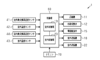
- the block diagram which shows a refrigeration equipment notionally The block diagram which shows the electric constitution of a refrigeration equipment.
- three indoor units 20 installed indoors have three connecting pipes 31 and 3 on the liquid side with respect to one outdoor unit 10 installed outdoors.
- This is a multi-type air conditioner connected in parallel with the gas side communication pipe 32 of the book.
- the outdoor unit 10 is an example of a heat source side device
- the indoor unit 20 is an example of a usage side device.
- the number of indoor units 20 connected to one outdoor unit 10 is three. It is not limited and can be changed arbitrarily. For example, two indoor units 20 may be connected to one outdoor unit 10, or four or more indoor units 20 may be connected to one outdoor unit 10.
- the outdoor unit 10 is provided with a compressor 11 whose rotation speed is variable by an inverter, and a four-way switching valve 12 connected to a discharge pipe and a suction pipe of the compressor 11, and the compressor 11 and the four-way switching valve 12 are provided.
- An accumulator 13 is connected in the middle of a suction pipe that connects to and.
- the outdoor unit 10 includes an outdoor heat exchanger 14, which is an example of a heat source-side heat exchanger, three electric expansion valves 15 connected in parallel, and three with respect to one switching port of the four-way switching valve 12.
- the liquid-side communication pipe connecting portion 16 is sequentially connected.
- the electric expansion valve 15 is an example of an expansion valve.
- the outdoor unit 10 is connected to the other switching port of the four-way switching valve 12 with three gas-side communication pipe connecting portions 17 connected in parallel.
- the outdoor unit 10 is provided with an outdoor blower 18 for circulating the outside air to the outdoor heat exchanger 14.
- a propeller fan can be used as an example of the outdoor blower 18.
- Each indoor unit 20 is equipped with an indoor heat exchanger 21, which is an example of a use side heat exchanger, and an indoor blower 22 for circulating indoor air to the indoor heat exchanger 21.
- An indoor blower 22 for circulating indoor air to the indoor heat exchanger 21.
- a sirocco fan can be used as an example of the indoor blower 22.
- the refrigerant circuit 30 is reversibly switched by switching the four-way switching valve 12, the cooling operation is performed by the cooling cycle, and the heating operation is performed by the heating cycle.
- the refrigeration system 1 sets the four-way switching valve 12 to the connection position indicated by the solid line arrow during the cooling operation. Then, the compressor 11, the four-way switching valve 12, the outdoor heat exchanger 14, the electric expansion valve 15, the liquid side connecting pipe connecting portion 16, the liquid side connecting pipe 31, the indoor heat exchanger 21, the gas side connecting pipe 32. , The gas-side communication pipe connection part 17, the four-way switching valve 12, the accumulator 13, and the compressor 11 in this order form a refrigerant circuit 30 that forms a cooling cycle for circulating the refrigerant. Further, the refrigeration system 1 sets the four-way switching valve 12 to the connection position indicated by the broken line arrow during the heating operation.
- the valve 15, the outdoor heat exchanger 14, the four-way switching valve 12, the accumulator 13, and the compressor 11 form a refrigerant circuit 30 that forms a heating cycle in which the refrigerant circulates in this order.
- the outdoor heat exchanger 14 functions as a condenser and the indoor heat exchanger 21 functions as an evaporator, whereby the indoor air circulated by the indoor blower 22 is cooled and dehumidified, The room is cooled.
- the indoor heat exchanger 21 acts as a condenser and the outdoor heat exchanger 14 acts as an evaporator, so that the indoor air circulated by the indoor blower 22 is heated. The room is heated.
- the refrigeration system 1 is provided with various temperature sensors such as an outdoor heat exchanger temperature sensor 41, an outdoor temperature sensor 42, an indoor temperature sensor 43, and an indoor heat exchanger temperature sensor 44.
- various temperature sensors for example, known temperature sensors can be used.
- the outdoor heat exchanger temperature sensor 41 is provided in the outdoor heat exchanger 14 of the outdoor unit 10 and detects the condensation temperature during the cooling operation.
- the outdoor temperature sensor 42 is provided in the outdoor unit 10 and detects the temperature (outdoor air temperature) of the outdoor air sent to the outdoor heat exchanger 14.
- the indoor temperature sensor 43 is provided in the indoor unit 20, and detects the temperature of the indoor air sent to the indoor heat exchanger 21 (indoor temperature).
- the indoor heat exchanger temperature sensor 44 is provided in the indoor heat exchanger 21 and detects the evaporation temperature during the cooling operation.
- the refrigeration system 1 includes a bypass passage 50 and a bypass valve 51.
- the bypass passage 50 is a portion of the refrigerant circuit 30 downstream of the four-way switching valve 12 and upstream of the indoor heat exchanger 21, and downstream of the electric expansion valve 15 and outdoor heat in the refrigerant flow during heating operation for heating. It connects to the upstream portion of the exchanger 14.
- one connection end of the bypass passage 50 is connected to the pipe 33 that connects the four-way switching valve 12 and the gas side communication pipe connecting portion 17.
- one of the connection ends of the bypass passage 50 connects the three branch pipes 33 a and the four-way switching valve 12 in which the pipe 33 of the pipe 33 is branched to be connected to the gas side communication pipe connecting portion 17.
- the other connection end of the bypass passage 50 is connected to the pipe 34 that connects the outdoor heat exchanger 14 and the electric expansion valve 15. Specifically, the other connection end of the bypass passage 50 connects the outdoor heat exchanger 14 with the three branch pipes 34 a that are branched from the pipe 34 of the pipe 34 and are connected to the liquid side communication pipe connection portion 16. It is connected to the part between.
- An electric expansion valve 15 is provided in each of the three branch pipes 34a.
- the bypass path 50 is composed of, for example, piping.
- the inner diameter of the pipe forming the bypass 50 is, for example, less than or equal to the inner diameter of the pipe 33, or less than or equal to the inner diameter of the pipe 34.
- the inner diameter of the pipe forming the bypass 50 can be arbitrarily changed.
- the inner diameter of the pipe forming the bypass 50 may be equal to or larger than the inner diameter of the pipe 33 or may be equal to or larger than the inner diameter of the pipe 34.
- a capillary tube may be provided in a portion between the one connection end of the bypass passage 50 and the bypass valve 51.
- the bypass valve 51 is provided in the bypass passage 50 and can open and close the bypass passage 50.
- the bypass valve 51 may be, for example, an opening / closing valve that is an electromagnetic valve or an electric valve that can adjust the opening.
- the refrigeration system 1 includes a control unit 60 that controls the operation of the refrigeration system 1.
- the control unit 60 includes an outdoor control unit 19 provided in the outdoor unit 10 and an indoor control unit 23 provided in the indoor unit 20.
- the outdoor control unit 19 and the indoor control unit 23 are electrically connected to each other.
- Each of the outdoor control unit 19 and the indoor control unit 23 includes, for example, an arithmetic unit that executes a predetermined control program and a storage unit.
- the arithmetic processing unit includes, for example, a CPU (Central Processing Unit) or an MPU (Micro Processing Unit).
- the storage unit stores various control programs and information used for various control processes.
- the storage unit includes, for example, a non-volatile memory and a volatile memory.
- a compressor 11, a four-way switching valve 12, an electric expansion valve 15, an outdoor blower 18, an outdoor heat exchanger temperature sensor 41, an outdoor temperature sensor 42, and a bypass valve 51 are electrically connected to the outdoor controller 19. There is.
- the outdoor control unit 19 controls the compressor 11, the four-way switching valve 12, the electric expansion valve 15, the outdoor blower 18, and the bypass valve 51.
- the indoor blower 22, the indoor temperature sensor 43, the indoor heat exchanger temperature sensor 44, and the remote controller 70 are electrically connected to the indoor control unit 23.
- the indoor control unit 23 controls the indoor blower 22.
- the remote controller 70 functions as a driving operation unit for the refrigeration system 1.
- the remote controller 70 includes an operation switch for turning on / off the operation of the refrigeration apparatus 1, an operation mode selection unit for selecting an operation mode such as cooling operation, heating operation, an air volume setting unit for setting the air volume of the indoor blower 22, and a set temperature of the indoor temperature
- a temperature setting unit for setting (indoor set temperature), a display unit for displaying the set temperature of indoor air, the current indoor temperature, and the like are provided.
- the remote controller 70 is configured to be capable of wirelessly communicating driving operation information or the like selected or set with the indoor control unit 23.
- the outdoor control unit 19 switches the four-way switching valve 12 to the position shown by the solid line in FIG. 1 so that the refrigerant circuit 30 enters the cooling cycle at the start of the cooling operation. Then, the outdoor control unit 19 controls the operating frequency of the compressor 11 and the rotation speed of the outdoor blower 18 in accordance with the difference between the indoor temperature and the indoor set temperature, and controls the superheat degree of the refrigerant at the outlet of the indoor heat exchanger 21. Accordingly, the opening degree of the electric expansion valve 15 is controlled.
- the outdoor control unit 19 feedback-controls the operating frequency of the compressor 11 so that the difference between the indoor temperature and the indoor set temperature becomes “0”. That is, the outdoor control unit 19 lowers the operating frequency of the compressor 11 as the indoor temperature approaches the indoor set temperature.
- the indoor control unit 23 controls the rotation speed of the indoor blower 22 according to the difference between the indoor temperature and the indoor set temperature.
- the indoor control unit 23 stores a map M1 of the blown air volume of the indoor blower 22 based on the difference between the indoor temperature and the indoor set temperature.
- the indoor control unit 23 controls the blown air volume of the indoor blower 22 using the map M1.
- the outdoor control unit 19 switches the four-way switching valve 12 to the broken line position in FIG. 1 so that the refrigerant circuit 30 enters the heating cycle when the heating operation is started. Then, the outdoor control unit 19 controls the operating frequency of the compressor 11 and the rotation speed of the outdoor blower 18 in accordance with the difference between the indoor temperature and the indoor set temperature, and controls the superheat degree of the refrigerant at the outlet of the indoor heat exchanger 21. Accordingly, the opening degree of the electric expansion valve 15 is controlled. In one example, the outdoor control unit 19 feedback-controls the operating frequency of the compressor 11 so that the difference between the indoor temperature and the indoor set temperature becomes “0”. That is, the outdoor control unit 19 lowers the operating frequency of the compressor 11 as the indoor temperature approaches the indoor set temperature.
- the indoor control unit 23 controls the rotation speed of the indoor blower 22 according to the difference between the indoor temperature and the indoor set temperature.
- the indoor control unit 23 stores a map M2 of the blown air volume of the indoor blower 22 based on the difference between the indoor temperature and the indoor set temperature.
- the indoor control unit 23 controls the blown air volume of the indoor blower 22 using the map M2.
- the map M2 may be the same as or different from the map M1.
- the outdoor control unit 19 starts the defrosting operation when the temperature of the outdoor heat exchanger 14 becomes equal to or lower than the first threshold value TX1 during the heating operation.
- the first threshold TX1 is a temperature at which the fins of the outdoor heat exchanger 14 are likely to frost, and is set in advance by a test or the like.
- the outdoor control unit 19 executes the defrosting operation for a predetermined time from the start of the defrosting operation.
- the outdoor control unit 19 switches the four-way switching valve 12 to the position shown by the solid line in FIG. 1 so that the refrigerant circuit 30 enters the cooling cycle at the start of the defrosting operation, and stops the operation of the outdoor blower 18.
- the outdoor control unit 19 maintains the opening degree of the electric expansion valve 15 at the same opening degree as during the heating operation, for example.
- the outdoor control unit 19 may set the opening degree of the electric expansion valve 15 to a predetermined opening degree at the start of the defrosting operation.
- the indoor control unit 23 also stops the operation of the indoor blower 22.
- the outdoor control unit 19 has an open state in which the bypass valve 51 is opened to open the bypass 50 and a closed state in which the bypass valve 51 is closed to close the bypass 50 in at least one of the heating operation and the cooling operation. It is configured to be switchable to and. In the present embodiment, the outdoor control unit 19 is configured to be able to switch the bypass path 50 between the open state and the closed state in each of the heating operation and the cooling operation. For example, the outdoor control unit 19 controls the bypass valve 51 to switch the bypass 50 from the closed state to the open state when the first condition is satisfied in the heating operation. When the second condition is satisfied in the cooling operation, the outdoor control unit 19 controls the bypass valve 51 to switch the bypass path 50 from the closed state to the open state.
- the first condition and the second condition are conditions in which it is necessary to reduce the amount of refrigerant flowing through the indoor heat exchanger 21, and are set in advance.
- the outdoor control unit 19 controls the bypass valve 51 so that the bypass valve 51 is fully closed so that the bypass passage 50 is closed and the bypass valve 51 is fully opened.
- the bypass path 50 is opened by controlling
- the outdoor controller 19 does not have to fully open the bypass valve 51.
- the opening degree of the bypass valve 51 can be arbitrarily changed.
- the outdoor control unit 19 may change the opening degree of the bypass valve 51 according to the capacity of the indoor unit 20.
- the bypass valve 51 does not have to be fully closed.
- the bypass valve 51 is an electromagnetic valve
- the bypass valve 51 may be in a closed state and the bypass valve 51 may be in a slightly open state.
- the outdoor control unit 19 may control the opening of the bypass valve 51 so that the bypass valve 51 is not fully closed.
- the outdoor control unit 19 controls the bypass valve 51 to be smaller than the opening of the bypass valve 51 when the bypass 50 is open. Specifically, when the bypass 50 is closed, the outdoor control unit 19 controls the bypass valve 51 so that the opening degree of the bypass valve 51 is less than the threshold value.
- the threshold value can be arbitrarily set in a range equal to or smaller than the opening degree of the bypass valve 51 when the bypass passage 50 is in the open state.
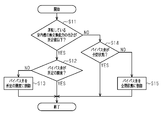
- FIG. 3 shows an example of a procedure of control processing of the bypass valve 51 in the heating operation.
- the control process of FIG. 3 is repeatedly executed at every predetermined period from the start of the heating operation.
- the outdoor control unit 19 determines whether the total heat exchange capacity of the operating indoor units 20 of the plurality of indoor units 20 connected in parallel to the outdoor unit 10 is less than or equal to the predetermined value X1.
- the operating indoor unit 20 is an indoor unit in which the indoor blower 22 is driven and the corresponding electric expansion valve 15 is in the open state, and the indoor unit 20 that is not in operation stops the indoor blower 22.
- the corresponding electric expansion valve 15 is a closed (or nearly closed) indoor unit.
- the outdoor control unit 19 calculates the heat exchange capacity of the indoor units 20 for each indoor unit 20 that is operating under the operating air volume at that time, and totals the heat exchange capacities of the indoor units 20. .. Specifically, the outdoor control unit 19 calculates the heat exchange capacity of each indoor unit 20 based on the heat exchange capacity defined by the size and material of the indoor heat exchanger 21 and the air volume of the indoor blower 22, The total heat exchange capacity of the indoor units 20 in operation is calculated by totaling the heat exchange capacity of the indoor units 20 in operation.
- the predetermined value X1 is a value for determining that it is necessary to reduce the amount of refrigerant flowing through the indoor heat exchanger 21, and is determined in advance by a test or the like.
- the outdoor control unit 19 determines whether or not the total heat exchange capacity of the operating indoor units 20 is equal to or less than the predetermined value X1.
- step S11 corresponds to the determination of whether or not the first condition is satisfied.
- the total heat exchange capacity of the operating indoor unit 20 includes the heat exchange capacity defined by the size and material of the indoor heat exchanger 21, the air volume of the indoor blower 22, and the rated capacity of the indoor unit 20. It may be calculated based on.
- the outdoor control unit 19 proceeds to step S12 when the total heat exchange capacity of the operating indoor units 20 of the plurality of indoor units 20 connected in parallel to the outdoor unit 10 is the predetermined value X1 or less.
- the outdoor control unit 19 determines whether or not the bypass valve 51 has a predetermined opening degree in step S12.
- An example of the predetermined opening is an opening corresponding to the bypass valve 51 in the fully open state.
- the outdoor control unit 19 proceeds to step S13.
- the outdoor control unit 19 controls the bypass valve 51 in step S13 so that the bypass valve 51 has a predetermined opening degree, and once ends the processing. As a result, the bypass 50 is switched from the closed state to the open state.
- the outdoor control unit 19 once ends the process. In this case, the bypass path 50 is maintained in the open state.
- step S14 If the total heat exchange capacity of the operating indoor units 20 of the plurality of indoor units 20 connected in parallel to the outdoor unit 10 is larger than the predetermined value X1, the outdoor control unit 19 proceeds to step S14. ..
- the outdoor control unit 19 determines in step S14 whether the bypass valve 51 is in the fully closed state. When the bypass valve 51 is not in the fully closed state, that is, when the bypass valve 51 is in the open state, the outdoor control unit 19 proceeds to step S15.
- the outdoor control unit 19 puts the bypass valve 51 into the fully closed state in step S15, and once ends the processing. As a result, the bypass 50 is switched from the open state to the closed state.
- the outdoor control unit 19 once ends the process. In this case, the bypass passage 50 is maintained in the closed state.
- the bypass passage 50 is opened, so that one of the refrigerants flowing from the compressor 11 to the indoor heat exchanger 21 is discharged. Part flows into the bypass passage 50. That is, the refrigerant discharged from the compressor 11 flows into the outdoor heat exchanger 14 via the bypass passage 50. As a result, the amount of refrigerant flowing through the indoor heat exchanger 21 is reduced.
- the bypass passage 50 is closed, so that the refrigerant flowing from the compressor 11 to the indoor heat exchanger 21 is A part does not flow to the bypass 50. Therefore, the decrease in the heating capacity of the indoor unit 20 is suppressed.
- step S11 corresponds to the determination of whether or not the second condition is satisfied in the control process of the bypass valve 51 in the cooling operation.
- the predetermined value X1 in step S11 in the control process for the bypass valve 51 in the cooling operation may be the same as or different from the predetermined value X1 in step S11 in the control process for the bypass valve 51 in the heating operation.
- the bypass passage 50 is in the open state, so that the air flows from the compressor 11 to the indoor heat exchanger 21. A part of the refrigerant to be circulated flows into the bypass passage 50. That is, the refrigerant flowing out of the outdoor heat exchanger 14 from the compressor 11 flows into the compressor 11 via the bypass passage 50. As a result, the amount of refrigerant flowing through the indoor heat exchanger 21 is reduced.
- the bypass passage 50 is closed, so that the compressor 11 moves from the indoor heat exchanger 21 to the indoor heat exchanger 21. A part of the circulating refrigerant does not flow into the bypass passage 50. Therefore, the decrease in the cooling capacity of the indoor unit 20 is suppressed.
- the outdoor control unit 19 is also configured to be able to set the bypass path 50 to the open state during the defrosting operation.
- the outdoor control unit 19 controls the bypass valve 51 so that the bypass passage 50 is opened when the normal operation such as the heating operation and the cooling operation is changed to the defrosting operation.
- FIG. 4 shows an example of a procedure of control processing of the bypass valve 51 in the defrosting operation.
- the control process of FIG. 4 is repeatedly executed every predetermined period.
- the outdoor control unit 19 determines whether to start the defrosting operation in step S21. When the outdoor control unit 19 determines not to start the defrosting operation, the outdoor control unit 19 temporarily ends the process. When the outdoor control unit 19 determines to start the defrosting operation, the outdoor control unit 19 proceeds to step S22.
- the outdoor control unit 19 determines in step S22 whether the bypass valve 51 has a predetermined opening.
- An example of the predetermined opening is an opening corresponding to the bypass valve 51 in the fully open state.
- the predetermined opening degree in step S22 may be the same as the predetermined opening degree of the bypass valve 51 in step S12 of FIG. 3, or may be a different opening degree.
- step S22 When the outdoor control unit 19 determines in step S22 that the bypass valve 51 is not at the predetermined opening degree, the outdoor control unit 19 proceeds to step S23.
- the outdoor control unit 19 controls the bypass valve 51 so that the bypass valve 51 has a predetermined opening degree in step S23, and proceeds to step S24.
- the outdoor control part 19 transfers to step S24, when the bypass valve 51 is a predetermined opening degree.
- the outdoor control unit 19 determines in step S24 whether or not the defrosting operation has ended.
- the outdoor control unit 19 makes the determination in step S24, for example, depending on whether or not a predetermined time has elapsed from the start of the defrosting operation.
- the outdoor control unit 19 proceeds to step S25.
- the outdoor control unit 19 controls the bypass valve 51 to switch the bypass path 50 from the open state to the closed state in step S25, and ends the process. If the outdoor control unit 19 determines in step S24 that the defrosting operation has not ended, the outdoor control unit 19 proceeds to step S24 again. In this way, the outdoor control unit 19 controls the bypass valve 51 to open the bypass passage 50 when starting the defrosting operation and to close the bypass passage 50 when ending the defrosting operation. ..
- the compressor is stopped, and when the indoor temperature of the operating indoor unit deviates from the indoor set temperature, the operation of the compressor is repeated again. That is, in the multi-type air conditioner, when the total heat exchange capacity of the operating indoor units is small, the start and stop of the compressor 11 is repeated.
- the heat exchanging capacity of the operating indoor units 20 is excessive. If there is a high possibility that the bypass path 50 will be changed, the bypass path 50 is switched from the closed state to the open state. As a result, a part of the refrigerant flowing from the compressor 11 to the indoor heat exchanger 21 flows through the bypass passage 50, so that the amount of the refrigerant flowing to the indoor heat exchanger 21 is reduced. For this reason, the heat exchange capacity of the indoor unit 20 is reduced, and the compressor 11 is less likely to stop.
- the outdoor control unit 19 controls the bypass valve 51 so that the bypass passage 50 switches between the closed state and the open state in each of the heating operation and the cooling operation.
- the bypass passage 50 since the bypass passage 50 can be opened in each of the heating operation and the cooling operation, a part of the refrigerant is circulated in the bypass passage 50 as needed in each of the heating operation and the cooling operation. be able to. In this way, the refrigerant can be circulated through the bypass 50 in the operation other than the defrosting operation, so that the convenience of the bypass 50 can be improved.
- the outdoor control unit 19 controls the bypass valve 51 so that the bypass passage 50 switches between the open state and the closed state during the heating operation, and the bypass valve 51 so that the bypass passage 50 is opened during the defrosting operation.
- a part of the refrigerant can be circulated through the bypass passage 50 as needed during the heating operation. That is, since the refrigerant can be circulated through the bypass 50 in operations other than the defrosting operation, the convenience of the bypass 50 can be improved.
- the outdoor control unit 19 changes the bypass 50 from the closed state to the open state.
- the bypass valve 51 is controlled as described above. According to this configuration, in each of the heating operation and the cooling operation, the amount of refrigerant flowing through the indoor heat exchanger 21 is reduced, so that the heat exchange capacity (heating capacity or cooling capacity) of the indoor unit 20 is reduced. Therefore, it is possible to prevent the compressor 11 from being repeatedly started and stopped, so that it is difficult to apply a load to the compressor 11, and it is possible to suppress a decrease in the life of the compressor 11.
- the above description regarding the embodiment is an example of a form that the refrigeration apparatus according to the present disclosure can take, and is not intended to limit the form.
- the refrigerating apparatus according to the present disclosure can take a form in which, for example, modifications of the above-described embodiment described below and at least two modifications that do not contradict each other are combined.
- the same parts as those of the above-described embodiment are designated by the same reference numerals and the description thereof will be omitted.
- control unit that controls the bypass valve 51 is not limited to the outdoor control unit 19.
- the control unit that controls the bypass valve 51 may be provided separately from the outdoor control unit 19. In this case, the control unit that controls the bypass valve 51 is included in the control unit 60.
- the second condition for switching the bypass 50 from the closed state to the open state during the heating operation is that the total heat exchange capacity of the indoor units 20 that is operating is equal to or less than the predetermined value X1.
- the content of the second condition is not limited to this.
- the outdoor control unit 19 may control the bypass valve 51 to switch the bypass passage 50 from the closed state to the open state when the predetermined condition regarding the pressure of the refrigerant flowing through the indoor unit 20 is satisfied in the heating operation.
- the predetermined condition regarding the pressure of the refrigerant is that the pressure of the refrigerant estimated by the blown air volume of the indoor blower 22, the outside air temperature, the number of operating indoor units 20, and the like is a predetermined value or more.
- the pressure of the refrigerant may be directly detected by, for example, a sensor.
- FIG. 5 is a flowchart showing an example of control processing of the bypass valve 51.
- the control process of the bypass valve 51 is repeatedly executed at predetermined time intervals.
- the outdoor control unit 19 determines in step S31 whether or not the heating operation is being performed. When the heating operation is not being performed, the outdoor control unit 19 temporarily ends the process. When the heating operation is being performed, the outdoor control unit 19 proceeds to step S32.
- the outdoor control unit 19 determines in step S32 whether the pressure of the refrigerant is equal to or higher than the predetermined value X2. When the pressure of the refrigerant is equal to or higher than the predetermined value X2, the outdoor control unit 19 proceeds to step S33.
- the outdoor control unit 19 determines whether or not the bypass valve 51 has a predetermined opening degree in step S33.
- step S34 The outdoor control unit 19 controls the bypass valve 51 in step S34 so that the bypass valve 51 has a predetermined opening degree, and ends the process once.
- the outdoor control unit 19 proceeds to step S35.
- the outdoor control unit 19 determines in step S35 whether the bypass valve 51 is in the fully closed state. The outdoor control unit 19 once ends the process when the bypass valve 51 is in the fully closed state. When the bypass valve 51 is not in the fully closed state, the outdoor control unit 19 brings the bypass valve 51 into the fully closed state in step S36, and ends the process once.
- the outdoor control unit 19 controls to reduce the operating frequency of the compressor 11. May be added.
- FIG. 6 is a flowchart showing an example of control processing of the bypass valve 51.
- step S11 When the outdoor control unit 19 determines in step S11 that the total heat exchange capacity of the operating indoor units 20 is larger than the predetermined value X1, the process proceeds to step S41.
- the outdoor control unit 19 determines in step S41 whether the pressure of the refrigerant is equal to or higher than the predetermined value X2. When the pressure of the refrigerant is equal to or higher than the predetermined value X2, the outdoor control unit 19 proceeds to step S12. When the pressure of the refrigerant is less than the predetermined value X2, the outdoor control unit 19 proceeds to step S14.
- the outdoor control unit 19 determines that the bypass passage 50 is in the open state when the pressure of the refrigerant is equal to or higher than the predetermined value X2 even when the heat exchange capacity of the operating indoor unit 20 is larger than the predetermined value X1.
- the bypass valve 51 is controlled so that
- steps S12 and S14 may be omitted from the flowchart of FIG.
- the outdoor control unit 19 proceeds to step S13 if an affirmative determination is made in step S11, and proceeds to step S15 if a negative determination is made in step S11.
- the bypass valve 51 is in a closed state in which the bypass valve 51 is fully closed, and the interior of the operating room
- the bypass valve 51 is in the open state in which it is fully opened.
- the processing content of step S11 may be changed as follows. That is, the outdoor control unit 19 determines whether the number of operating indoor units 20 of the plurality of indoor units 20 connected in parallel to the outdoor unit 10 is less than or equal to a predetermined number in step S11.
- the predetermined number is one. The predetermined number can be arbitrarily changed within a range smaller than the total number of indoor units 20 connected in parallel to one outdoor unit 10.
- step S22 when the defrosting operation is started when the bypass 50 is closed during the cooling operation and the heating operation, step S22 may be omitted from the flowchart of FIG. In this case, when the outdoor control unit 19 makes a positive determination in step S21, the outdoor control unit 19 proceeds to step S23.
- the outdoor control unit 19 switches the bypass passage 50 from the closed state to the open state when the third condition is satisfied, instead of opening the bypass passage 50 at the start of the defrosting operation.
- the bypass valve 51 may be controlled as described above. In one example, when the temperature of the outdoor heat exchanger 14 is equal to or lower than the second threshold value TX2 lower than the first threshold value TX1 as the third condition, the outdoor control unit 19 switches the bypass path 50 from the closed state to the open state.
- the bypass valve 51 is controlled. In this case, when the temperature of the outdoor heat exchanger 14 is higher than the second threshold value TX2 and lower than the first threshold value TX1, the outdoor control unit 19 performs the defrosting operation but does not open the bypass valve 51.
- the outdoor control unit 19 controls the bypass valve 51 so as to switch the bypass passage 50 between the open state and the closed state during the heating operation, so that the bypass passage 50 maintains the closed state during the cooling operation.
- the bypass valve 51 may be controlled.
- the outdoor control unit 19 controls the bypass valve 51 so as to switch the bypass passage 50 between the open state and the closed state during the cooling operation, and controls the bypass valve 51 so that the bypass passage 50 maintains the closed state during the heating operation. You may control.
- the outdoor control unit 19 may control the bypass valve 51 so that the bypass passage 50 switches between the closed state and the open state in at least one of the heating operation and the cooling operation.
- the bypass passage 50 can be opened in at least one of the heating operation and the cooling operation, and therefore, in at least one of the heating operation and the cooling operation, a part of the refrigerant is supplied to the bypass passage 50 as necessary. It can be distributed. In this way, the refrigerant can be circulated through the bypass 50 in the operation other than the defrosting operation, so that the convenience of the bypass 50 can be improved.
- the present disclosure is applied to a multi-type air conditioner in which a plurality of indoor units 20 are connected to one outdoor unit 10, but the present disclosure is not limited to this, and one outdoor unit 10 is not limited thereto.
- the outdoor control unit 19 controls the bypass valve 51 so that the bypass passage 50 changes from the closed state to the open state when the predetermined condition is satisfied in at least one of the heating operation and the cooling operation.
- the predetermined condition is, for example, a predetermined condition regarding the pressure of the refrigerant.
- the predetermined condition is, for example, that the pressure of the refrigerant determined by the blown air volume of the indoor blower 22, the outside air temperature, or the like is equal to or more than a predetermined value.
- the pressure of the refrigerant may be directly detected by, for example, a sensor.
Landscapes
- Engineering & Computer Science (AREA)
- Physics & Mathematics (AREA)
- Mechanical Engineering (AREA)
- Thermal Sciences (AREA)
- General Engineering & Computer Science (AREA)
- Air Conditioning Control Device (AREA)
Abstract
Appareil de réfrigération qui comprend un compresseur, une soupape de commutation à quatre voies, un échangeur de chaleur côté source de chaleur, un détendeur, un échangeur de chaleur côté utilisation, et un circuit frigorifique configuré de telle sorte qu'un fluide frigorigène y circule. Le circuit frigorifique comprend un passage de dérivation, une soupape de dérivation qui est disposée dans le passage de dérivation et peut ouvrir et fermer le passage de dérivation, et une unité de commande qui commande le fonctionnement de l'appareil de réfrigération. Le passage de dérivation relie une partie du circuit frigorifique en aval de la soupape de commutation à quatre voies et en amont de l'échangeur de chaleur côté utilisation et une partie du circuit frigorifique en aval du détendeur et en amont de l'échangeur de chaleur côté source de chaleur, dans un écoulement de fluide frigorigène pendant une opération de chauffage d'espace consistant à réaliser un chauffage d'espace. L'unité de commande est configurée pour être commutable entre un état ouvert dans lequel le passage de dérivation est ouvert par ouverture de la soupape de dérivation et un état fermé dans lequel le passage de dérivation est fermé par fermeture de la soupape de dérivation, dans au moins une parmi l'opération de chauffage d'espace consistant à réaliser le chauffage d'espace et une opération de refroidissement d'espace consistant à réaliser un refroidissement d'espace.
Applications Claiming Priority (2)
| Application Number | Priority Date | Filing Date | Title |
|---|---|---|---|
| JP2018206468A JP2020070995A (ja) | 2018-11-01 | 2018-11-01 | 冷凍装置 |
| JP2018-206468 | 2018-11-01 |
Publications (1)
| Publication Number | Publication Date |
|---|---|
| WO2020090635A1 true WO2020090635A1 (fr) | 2020-05-07 |
Family
ID=70462455
Family Applications (1)
| Application Number | Title | Priority Date | Filing Date |
|---|---|---|---|
| PCT/JP2019/041838 Ceased WO2020090635A1 (fr) | 2018-11-01 | 2019-10-25 | Appareil de réfrigération |
Country Status (2)
| Country | Link |
|---|---|
| JP (1) | JP2020070995A (fr) |
| WO (1) | WO2020090635A1 (fr) |
Families Citing this family (1)
| Publication number | Priority date | Publication date | Assignee | Title |
|---|---|---|---|---|
| US20240367484A1 (en) * | 2023-05-03 | 2024-11-07 | Denso International America, Inc. | Refrigerant loops and related control systems for heating and cooling |
Citations (6)
| Publication number | Priority date | Publication date | Assignee | Title |
|---|---|---|---|---|
| JPH07239157A (ja) * | 1994-02-28 | 1995-09-12 | Sanyo Electric Co Ltd | 空調機の運転制御方法 |
| JPH10148379A (ja) * | 1996-11-20 | 1998-06-02 | Sanyo Electric Co Ltd | 輻射空調システム |
| JP2006105560A (ja) * | 2004-10-08 | 2006-04-20 | Matsushita Electric Ind Co Ltd | 空気調和装置 |
| EP2184561A1 (fr) * | 2008-11-10 | 2010-05-12 | Lg Electronics Inc. | Système de climatisation |
| US20130118193A1 (en) * | 2011-11-16 | 2013-05-16 | Industrial Technology Research Institute | Heat pump air-conditioning system and method for controlling the same |
| JP2018096575A (ja) * | 2016-12-09 | 2018-06-21 | ダイキン工業株式会社 | 冷凍装置 |
Family Cites Families (2)
| Publication number | Priority date | Publication date | Assignee | Title |
|---|---|---|---|---|
| JP2508043B2 (ja) * | 1987-01-12 | 1996-06-19 | ダイキン工業株式会社 | 冷凍装置の圧縮機容量制御装置 |
| US8899052B2 (en) * | 2010-11-04 | 2014-12-02 | International Business Machines Corporation | Thermoelectric-enhanced, refrigeration cooling of an electronic component |
-
2018
- 2018-11-01 JP JP2018206468A patent/JP2020070995A/ja active Pending
-
2019
- 2019-10-25 WO PCT/JP2019/041838 patent/WO2020090635A1/fr not_active Ceased
Patent Citations (6)
| Publication number | Priority date | Publication date | Assignee | Title |
|---|---|---|---|---|
| JPH07239157A (ja) * | 1994-02-28 | 1995-09-12 | Sanyo Electric Co Ltd | 空調機の運転制御方法 |
| JPH10148379A (ja) * | 1996-11-20 | 1998-06-02 | Sanyo Electric Co Ltd | 輻射空調システム |
| JP2006105560A (ja) * | 2004-10-08 | 2006-04-20 | Matsushita Electric Ind Co Ltd | 空気調和装置 |
| EP2184561A1 (fr) * | 2008-11-10 | 2010-05-12 | Lg Electronics Inc. | Système de climatisation |
| US20130118193A1 (en) * | 2011-11-16 | 2013-05-16 | Industrial Technology Research Institute | Heat pump air-conditioning system and method for controlling the same |
| JP2018096575A (ja) * | 2016-12-09 | 2018-06-21 | ダイキン工業株式会社 | 冷凍装置 |
Also Published As
| Publication number | Publication date |
|---|---|
| JP2020070995A (ja) | 2020-05-07 |
Similar Documents
| Publication | Publication Date | Title |
|---|---|---|
| JP7186845B2 (ja) | 空気調和装置 | |
| US10323862B2 (en) | Air conditioning unit having dynamic target condensing and evaporating values based on load requirements | |
| CN101960232B (zh) | 制冷装置 | |
| US20180340700A1 (en) | Variable refrigerant flow system | |
| EP3062031A1 (fr) | Climatiseur | |
| JP6148001B2 (ja) | 空気調和機 | |
| US11199342B2 (en) | Air conditioner | |
| CN114127479B (zh) | 制冷装置 | |
| AU2014411657B2 (en) | Air-conditioning apparatus | |
| CN106440560B (zh) | 冷凝面积可调的空调系统及其控制方法 | |
| US20240167735A1 (en) | Heat source unit and air conditioner | |
| JPWO2019053876A1 (ja) | 空気調和装置 | |
| WO2014132433A1 (fr) | Dispositif de climatisation | |
| JPWO2016170575A1 (ja) | 冷凍サイクル装置 | |
| JP2018204814A (ja) | 制御装置、それを備えたマルチ型空気調和システム、及び制御方法並びに制御プログラム | |
| JPWO2020174618A1 (ja) | 空気調和装置 | |
| CN110319542B (zh) | 一种大排量变频多联机系统的卸载启闭控制方法 | |
| JP7233568B2 (ja) | 空気調和システムおよびその制御方法 | |
| JP2020070995A (ja) | 冷凍装置 | |
| JP2014119154A (ja) | 空気調和機 | |
| JP6835055B2 (ja) | 冷凍装置 | |
| GB2541607A (en) | Refrigeration cycle device | |
| JPWO2018008130A1 (ja) | 空気調和装置 | |
| JP6203230B2 (ja) | 空調装置、空調装置の制御方法 | |
| WO2021214816A1 (fr) | Dispositif à cycle frigorifique, climatiseur, et dispositif de refroidissement |
Legal Events
| Date | Code | Title | Description |
|---|---|---|---|
| 121 | Ep: the epo has been informed by wipo that ep was designated in this application |
Ref document number: 19880653 Country of ref document: EP Kind code of ref document: A1 |
|
| NENP | Non-entry into the national phase |
Ref country code: DE |
|
| 122 | Ep: pct application non-entry in european phase |
Ref document number: 19880653 Country of ref document: EP Kind code of ref document: A1 |