WO2020090655A1 - グリッパ、及びシステム - Google Patents
グリッパ、及びシステム Download PDFInfo
- Publication number
- WO2020090655A1 WO2020090655A1 PCT/JP2019/041909 JP2019041909W WO2020090655A1 WO 2020090655 A1 WO2020090655 A1 WO 2020090655A1 JP 2019041909 W JP2019041909 W JP 2019041909W WO 2020090655 A1 WO2020090655 A1 WO 2020090655A1
- Authority
- WO
- WIPO (PCT)
- Prior art keywords
- gripper
- pair
- master jaw
- sensor
- movable parts
- Prior art date
- Legal status (The legal status is an assumption and is not a legal conclusion. Google has not performed a legal analysis and makes no representation as to the accuracy of the status listed.)
- Ceased
Links
Images



Classifications
-
- B—PERFORMING OPERATIONS; TRANSPORTING
- B25—HAND TOOLS; PORTABLE POWER-DRIVEN TOOLS; MANIPULATORS
- B25J—MANIPULATORS; CHAMBERS PROVIDED WITH MANIPULATION DEVICES
- B25J15/00—Gripping heads and other end effectors
- B25J15/08—Gripping heads and other end effectors having finger members
-
- B—PERFORMING OPERATIONS; TRANSPORTING
- B25—HAND TOOLS; PORTABLE POWER-DRIVEN TOOLS; MANIPULATORS
- B25J—MANIPULATORS; CHAMBERS PROVIDED WITH MANIPULATION DEVICES
- B25J13/00—Controls for manipulators
- B25J13/08—Controls for manipulators by means of sensing devices, e.g. viewing or touching devices
- B25J13/088—Controls for manipulators by means of sensing devices, e.g. viewing or touching devices with position, velocity or acceleration sensors
-
- B—PERFORMING OPERATIONS; TRANSPORTING
- B25—HAND TOOLS; PORTABLE POWER-DRIVEN TOOLS; MANIPULATORS
- B25J—MANIPULATORS; CHAMBERS PROVIDED WITH MANIPULATION DEVICES
- B25J19/00—Accessories fitted to manipulators, e.g. for monitoring, for viewing; Safety devices combined with or specially adapted for use in connection with manipulators
- B25J19/02—Sensing devices
-
- G—PHYSICS
- G01—MEASURING; TESTING
- G01B—MEASURING LENGTH, THICKNESS OR SIMILAR LINEAR DIMENSIONS; MEASURING ANGLES; MEASURING AREAS; MEASURING IRREGULARITIES OF SURFACES OR CONTOURS
- G01B7/00—Measuring arrangements characterised by the use of electric or magnetic techniques
- G01B7/02—Measuring arrangements characterised by the use of electric or magnetic techniques for measuring length, width or thickness
- G01B7/023—Measuring arrangements characterised by the use of electric or magnetic techniques for measuring length, width or thickness for measuring distance between sensor and object
Definitions
- the present invention has been made in view of such circumstances, and an object of the present invention is to provide a gripper and a system that can save cost and time in a production line of a factory.
- a sensor housing space is provided between the pair of movable parts, and the object to be held (work) is configured to be able to house a predetermined sensor in a non-invasive manner in the sensor housing space,
- a predetermined sensor is implemented to measure a predetermined length depending on the distance between the pair of movable parts.
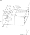
- FIG. 1A An overall perspective view of a gripper, which is an example of a sliding structure according to an embodiment of the present invention
- FIG. 1B An overall perspective view from an angle different from that of FIG. 1A.
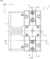
- FIG. 1B is a plan view of the gripper shown in FIGS. 1A and 1B.
- FIG. 3A A sectional view taken along the line AA in FIG. 2, showing a state where the plunger is displaced in the ⁇ y direction.
- FIG. 3B A sectional view taken along the line AA in FIG. 2, showing the plunger displaced in the + y direction. The state of doing.
- FIG. 1A An overall perspective view of a gripper, which is an example of a sliding structure according to an embodiment of the present invention
- FIG. 1B An overall perspective view from an angle different from that of FIG. 1A.
- FIG. 1B is a plan view of the gripper
- FIG. 3 is a perspective view of a plunger included in the gripper.
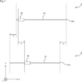
- FIG. 3 is a schematic view of the sensor, in which the upper part corresponds to a state where the master jaws are separated, and the lower part corresponds to a state where the master jaws are in close proximity.
- FIG. 3 is a sectional view taken along the line BB of FIG. 2 in which the sensor is attached to the gripper.
- FIGS. 1A and 1B are overall perspective views of the gripper 1
- FIG. 2 is a plan view of the gripper 1.
- 3A and 3B are sectional views taken along the line AA of FIG.
- the gripper 1 is configured to support a work (not shown) by a top jaw (not shown) when the work (not shown) is transported using an industrial robot (not shown).
- the gripper 1 has a main body 10, a rear cover 11, a master jaw 13, and a cover 14 which are visible from the outside.
- the gripper 1 includes a piston 15 and a plunger 16 inside the main body 10.
- FIG. 4 is a perspective view showing the main body 10 of the gripper 1.
- An inverted T-shaped groove 10T having a step 10Ta is formed in the main body 10 from the front side to the back side, that is, along the x-axis direction.
- a pair of master jaws 13 is provided in the groove 10T so as to be slidably fitted therein.
- the main body 10 is provided with a cylindrical blind hole 10h which is orthogonal to the groove 10T and engraves the surface 10Tb.
- the plunger 16 is fitted in the blind hole 10h. It is provided to do.
- FIG. 5 is a perspective view showing the master jaw 13 included in the gripper 1.
- the master jaw 13r on the right side of the pair of master jaws 13 is shown.
- the left master jaw 13l is symmetrical to the right master jaw 13r with respect to a plane of symmetry parallel to the yz plane.
- the master jaw 13 is configured in an inverted T-shape having a step 130 when viewed in the + x direction so as to fit in the groove 10T.
- the pair of master jaws 13 is arranged on the surface 10Tb which is a surface parallel to the xy plane.
- the step 10Ta in the main body 10 and the step 130 in the master jaw 13 are locked to each other, so that the master jaw 13 is not displaced in the z direction and is moved in the y direction. Does not displace, and is displaceable only in the x direction.
- the rectangular rear surface 131 of the master jaw 13 is provided with two parallel grooves 132.
- the parallel groove 132 extends obliquely from one long side 131a of the back surface 131 toward the other long side 131b and forms an angle ⁇ (for example, about 45 degrees) non-perpendicular to the long sides 131a and 131b. Has been formed.
- the parallel groove 132 is configured to be capable of fitting with a convex portion 162 (see FIG. 6) of the plunger 16 described later.
- the gripper 1 forms the space 104 surrounded by the left and right wall surfaces 135.
- the space 104 and the insertion hole 134 correspond to an example of "sensor housing space” in the claims. This will be discussed in more detail in Section 2.
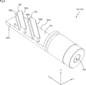
- FIG. 6 is a perspective view showing the plunger 16 included in the gripper 1.
- a pair of plungers 16 are provided so as to correspond to the pair of master jaws 13.
- the right plunger 16r corresponding to the right master jaw 13r is shown.
- the left plunger 16l is configured symmetrically with the right plunger 16r with respect to a plane of symmetry parallel to the yz plane.
- the plunger 16 is formed in a generally cylindrical shape, and a tip end portion (+ y side) thereof is cut off to form a rectangular flat plate portion 161 when viewed in the ⁇ z direction.
- the flat plate portion 161 is provided with two convex portions 162.
- the convex portion 162 is inclined from one long side 161a of the rectangular flat plate portion 161 toward the other long side 161b and forms an angle ⁇ (for example, about 45 degrees) that is non-perpendicular to the long sides 161a and 161b. Is formed in. With such a configuration, the parallel groove 132 in the master jaw 13 and the convex portion 162 in the plunger 16 are slidably fitted, and these correspond to an example of the “concave / convex structure” in the claims.
- a screw hole 163 is provided at the base end of the base of the plunger 16 (-y side).
- the piston 15 has a mounting hole 15a, and the bolt 15b is inserted into the mounting hole 15a, and the shaft portion thereof is screwed into the screw hole 163.
- the plunger 16 and the plunger 16 can be integrally fixed.
- the piston 15 is configured to be displaceable (sliding operation) in the ⁇ y directions by supplying / discharging air to / from the cylinder chamber of the piston 15 inside the main body 10.
- the plunger 16 is fitted in a cylindrical blind hole 10h formed so as to be orthogonal to the groove 10T and engrave the surface 10Tb. With such a configuration, the pair of plungers 16 fixed to the piston 15 can be displaced in the y direction along the blind hole 10h in association with the displacement of the piston 15 in the y direction.
- the master jaw 13 and the plunger 16 are orthogonally displaceable relative to each other by performing the above-described operation so that the sum of the angle ⁇ and the angle ⁇ becomes 90 degrees.
- the master jaw 13 fitted in the groove 10T of the main body 10 is configured to be displaceable only in the x direction in which the groove 10T extends. Therefore, when the plunger 16 is reciprocally displaced in the y direction by displacing the piston 15 in the y direction, the side wall 162a of the convex portion 162 presses the side wall 132a of the parallel groove 132 (or the side wall of the convex portion 162).
- the plunger 162b can press the side wall 132b of the parallel groove 132) to displace the master jaw 13 reciprocally in the x direction. Further, in the gripper 1, it can be said that the plunger 16 is configured to be displaceable on a predetermined surface parallel to the surface on which the pair of master jaws 13 is arranged (the surface parallel to the xy plane).
- the right master jaw 13r is displaced in the ⁇ x direction.
- the right master jaw 13r is displaced in the + x direction.
- the left master jaw 13l is displaced in the + x direction.
- the left master jaw 13l is displaced in the -x direction.
- the pair of master jaws 13 come close to each other, and when the pair of plungers 16 are displaced in the -y direction, the pair of master jaws 13 are separated from each other. It In this way, the pair of master jaws 13 can be opened and closed.
- the gripper 1 is constructed by incorporating the main components described above into the main body 10 and then attaching the rear cover 11 and the cover 14 as shown in FIG. Since the height of the master jaw 13 on the center side is low as the lower portion 133, even when the cover 14 is provided, the lower portion 133 goes under the cover 14 (in the ⁇ z direction) to form a pair.
- the master jaws 13 can be brought close to each other.
- a top jaw (not shown) is detachably arranged above the master jaw 13 (+ z direction), and a desired work is supported by the top jaw. At this time, it should be noted that the work supported by the top jaws does not enter the space 104 formed between the master jaws 13.
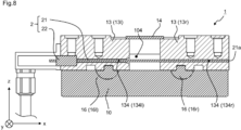
- the senor 2 includes an elongated scale rod 21 (an example of “an elongated member” in the claims) and a cylindrical (annular) reading unit 22 (a “annular member” in the claims). Member))).
- a reception unit (not shown) provided inside the reading unit 22 is provided.
- the machine measures the displacement.
- the sensor 2 having such a configuration is merely a preferable example, and the present invention is not limited to this.
- the sensor 2 may be configured such that the scale rod 21 is displaced in the longitudinal direction on the reading unit 22 formed in a flat plate shape instead of a cylindrical shape.
- the senor 2 may be configured such that two reading portions 22 formed in a flat plate shape are arranged so as to face each other, and the scale rod 21 is displaced in the longitudinal direction between them. Furthermore, you may employ
- aspects of such a system will be described in detail.
- the scale rod 21 extends from the one end 21a so as to pass through the insertion hole 134r and the space 104, further enters the insertion hole 134l provided in the left master jaw 13l, and is fixed inside the reading hole 134l.
- the part 22 is inserted.
- the method of fixing each of the scale rod 21 and the reading unit 22 is not particularly limited, and a mechanical method such as fitting may be used, or another substance such as an adhesive may be used.
- FIG. 7 shows a mode in which the master jaws 13 are displaced by the distance d in the approaching direction.
- gripper 1 according to the present embodiment may be further creatively devised in the following manner.
- one end 21a of the scale rod 21 is fixed inside the insertion hole 134r of the right master jaw 13r, and the reading unit 22 is fixed inside the left master jaw 13l.
- one end 21a of the scale rod 21 may be fixed inside the insertion hole 134l of the left master jaw 13l, and the reading unit 22 may be fixed inside the right master jaw 13r. In such a case, it is preferable to appropriately determine the shape of the insertion hole 134.
- the sensor 2 may be attached to a top jaw (not shown) or a pair of movable parts that interlock with the top jaw.
- the pair of movable parts may be configured to form at least a part of the sensor housing space therebetween.
- at least one of the movable parts may be provided with a hole corresponding to the insertion hole 134, and at least one of the one end 21a of the scale rod 21 and the reading part 22 may be fixed inside the hole.
- the sensor 2 measures a predetermined length depending on the opening / closing degree of the movable part, so that the outer diameter of the workpiece can also be measured depending on the opening / closing degree of the movable part.
- the sum of the angles ⁇ and ⁇ may be changed to 90 degrees, and the sum of the angles ⁇ and ⁇ may be set to 270 degrees, for example, the angles ⁇ and ⁇ may be 135 degrees.
- the movement of the master jaw 13 associated with the plunger 16 will be the opposite of the previous embodiment. That is, when the right plunger 16r is displaced in the + y direction, the right master jaw 13r is displaced in the + x direction. When the right plunger 16r is displaced in the -y direction, the right master jaw 13r is displaced in the -x direction. When the left plunger 16l is displaced in the + y direction, the left master jaw 13l is displaced in the -x direction.
- the gripper 1 includes at least a pair of movable parts (master jaws 13) that can be opened and closed, and is configured to pinch or release the object to be pinched based on the opening and closing of the movable parts (master jaws 13). At least a part of the sensor housing space (space 104) is formed between them, and the object to be sandwiched is housed in the sensor housing space (the space 104 and the insertion hole 134) in a non-penetrating manner.
- the predetermined sensor 2 is configured to be capable of measuring a predetermined length depending on the distance between the pair of movable parts (master jaws 13).
- a system comprising a gripper and a sensor, wherein the gripper is provided with at least a pair of movable parts that can be opened and closed, and is configured to pinch or release an object to be pinched based on the opening and closing, and The portion is configured to form at least a part of the sensor housing space between them, the sensor housing space is configured such that the object to be sandwiched is not invading and the sensor can be housed, and the sensor is By measuring a predetermined length depending on the distance between the pair of movable parts, the size of the object to be sandwiched can be measured, and the gripper holds the object to be sandwiched by the gripper.
- a system configured to carry an object and measure its size.
- the senor includes an elongated member and an annular member configured to allow the elongated member to be inserted, and a receiver provided on the annular member has the elongated member inserted into the annular member.
- a system capable of reading the displacement in the longitudinal direction of the elongated member, wherein one end of the elongated member is fixed to one of the pair of movable parts, and the annular member is fixed to the other of the pair of movable parts.
- the sensor housing space includes a hole formed in a longitudinal direction of at least one of the pair of movable parts, and one end of the elongated member and at least one of the annular member are fixed inside the hole. ,system.
- the movable part is a master jaw
- the gripper further comprises a plunger and a top jaw
- the plunger is displaceable on a predetermined plane parallel to a plane on which the master jaw is arranged.
- the master jaw is configured to slide along with the master jaw by being fitted to the master jaw along the concavo-convex structure so that the master jaw can be opened and closed.
- a system that is configured to be detachable and configured to be capable of sandwiching the object to be sandwiched in a state of being attached to the master jaw. Of course, this is not the case.
Landscapes
- Engineering & Computer Science (AREA)
- Robotics (AREA)
- Mechanical Engineering (AREA)
- Physics & Mathematics (AREA)
- General Physics & Mathematics (AREA)
- Human Computer Interaction (AREA)
- Manipulator (AREA)
- Clamps And Clips (AREA)
Abstract
Description
第1節では、グリッパ1の全体構成を説明する。図1A及び図1Bは、それぞれグリッパ1の全体斜視図であり、図2は、グリッパ1の平面図である。また、図3A及び図3Bは、図2のA-A断面図を示している。グリッパ1は、産業用ロボット(不図示)を用いてワーク(不図示)を運搬等する際に、当該ワークをトップジョー(不図示)によって支持するように構成される。図1A及び図1Bに示されるよう、グリッパ1は、本体10と、リアカバー11と、マスタージョー13と、カバー14とを外観から目視可能に有する。また、図3A及び図3Bに示されるように、グリッパ1は、ピストン15と、プランジャ16とを、本体10の内部に備えている。
第2節では、グリッパ1に取付可能なセンサー2について説明する。第1節において説明した通り、マスタージョー13の間に形成される空間104と、マスタージョー13に設けられた挿通孔134は、センサー2を取付可能なセンサー収容空間として構成される。図7は、センサー2の概要図であり、上部に示されるものはマスタージョー13が離間している状態に対応し、下部に示されるものはマスタージョー13が近接している状態に対応する。また、図8は、センサー2をグリッパ1に取り付けた状態での、図2のB-B断面図を示している。
なお、次のような態様によって、本実施形態に係るグリッパ1をさらに創意工夫してもよい。
以上のように、本実施形態によれば、工場の生産ライン等においてコストと時間とを節約することができるグリッパ1を実施することができる。
前記グリッパにおいて、前記センサー収容空間は、前記一対の可動部の少なくとも一方の長手方向に形成された穴を含む、グリッパ。
前記グリッパにおいて、プランジャをさらに備え、前記可動部は、トップジョーを着脱可能なマスタージョーであり、前記プランジャは、前記マスタージョーが配置される面に平行な所定の面上で変位可能に構成され、前記マスタージョーと凹凸構造に沿って嵌合されることで前記マスタージョーと連動して摺動し、これにより前記マスタージョーを開閉可能に構成される、グリッパ。
システムであって、グリッパと、センサーとを備え、前記グリッパは、開閉可能な少なくとも一対の可動部を備え、その開閉に基づいて被挟持物を挟持又は開放するように構成され、前記一対の可動部は、その間においてセンサー収容空間の少なくとも一部を形成するように構成され、前記センサー収容空間は、前記被挟持物が非侵入に、且つ前記センサーを収容可能に構成され、前記センサーは、前記一対の可動部間の距離に依存する所定の長さを測定することにより、前記被挟持物の大きさを測定可能に構成され、前記グリッパが前記被挟持物を挟持することによって、前記被挟持物の運搬とその大きさの測定とを実施可能に構成される、システム。
前記システムにおいて、前記センサーは、細長部材と、前記細長部材を挿通可能に構成される環状部材とを有し、前記環状部材に設けられた受信機が、前記環状部材に挿通された前記細長部材の長手方向の変位を読み取り可能に構成され、前記細長部材の一端が前記一対の可動部の一方に固定され、前記環状部材が前記一対の可動部の他方に固定される、システム。
前記システムにおいて、前記センサー収容空間は、前記一対の可動部の少なくとも一方の長手方向に形成された穴を含み、前記細長部材の一端及び前記環状部材の少なくとも一方が前記穴の内部に固定される、システム。
前記システムにおいて、前記可動部はマスタージョーであり、前記グリッパは、プランジャと、トップジョーとをさらに備え、前記プランジャは、前記マスタージョーが配置される面に平行な所定の面上で変位可能に構成され、前記マスタージョーと凹凸構造に沿って嵌合されることで前記マスタージョーと連動して摺動し、これにより前記マスタージョーを開閉可能に構成され、前記トップジョーは、前記マスタージョーに着脱可能に構成され、前記マスタージョーに取り付けられた状態において、前記被挟持物を挟持可能に構成される、システム。
もちろん、この限りではない。
104 :空間
13 :マスタージョー
134 :挿通孔
15 :ピストン
16 :プランジャ
2 :センサー
21 :スケールロッド
22 :読み取り部
Claims (7)
- グリッパであって、
開閉可能な少なくとも一対の可動部を備え、その開閉に基づいて被挟持物を挟持又は開放するように構成され、
前記一対の可動部は、その間においてセンサー収容空間の少なくとも一部を形成するように構成され、
前記センサー収容空間は、
前記被挟持物が非侵入に構成され、
所定のセンサーを収容可能に構成され、前記所定のセンサーは、前記一対の可動部間の距離に依存する所定の長さを測定する、
グリッパ。 - 請求項1に記載のグリッパにおいて、
前記センサー収容空間は、前記一対の可動部の少なくとも一方の長手方向に形成された穴を含む、
グリッパ。 - 請求項1又は請求項2に記載のグリッパにおいて、
プランジャをさらに備え、
前記可動部は、トップジョーを着脱可能なマスタージョーであり、
前記プランジャは、
前記マスタージョーが配置される面に平行な所定の面上で変位可能に構成され、
前記マスタージョーと凹凸構造に沿って嵌合されることで前記マスタージョーと連動して摺動し、これにより前記マスタージョーを開閉可能に構成される、
グリッパ。 - システムであって、
グリッパと、センサーとを備え、
前記グリッパは、開閉可能な少なくとも一対の可動部を備え、その開閉に基づいて被挟持物を挟持又は開放するように構成され、
前記一対の可動部は、その間においてセンサー収容空間の少なくとも一部を形成するように構成され、
前記センサー収容空間は、前記被挟持物が非侵入に、且つ前記センサーを収容可能に構成され、
前記センサーは、前記一対の可動部間の距離に依存する所定の長さを測定することにより、前記被挟持物の大きさを測定可能に構成され、
前記グリッパが前記被挟持物を挟持することによって、前記被挟持物の運搬とその大きさの測定とを実施可能に構成される、
システム。 - 請求項4に記載のシステムにおいて、
前記センサーは、
細長部材と、前記細長部材を挿通可能に構成される環状部材とを有し、
前記環状部材に設けられた受信機が、前記環状部材に挿通された前記細長部材の長手方向の変位を読み取り可能に構成され、
前記細長部材の一端が前記一対の可動部の一方に固定され、前記環状部材が前記一対の可動部の他方に固定される、
システム。 - 請求項5に記載のシステムにおいて、
前記センサー収容空間は、前記一対の可動部の少なくとも一方の長手方向に形成された穴を含み、
前記細長部材の一端及び前記環状部材の少なくとも一方が前記穴の内部に固定される、
システム。 - 請求項4~請求項6の何れか1つに記載のシステムにおいて、
前記可動部はマスタージョーであり、
前記グリッパは、プランジャと、トップジョーとをさらに備え、
前記プランジャは、
前記マスタージョーが配置される面に平行な所定の面上で変位可能に構成され、
前記マスタージョーと凹凸構造に沿って嵌合されることで前記マスタージョーと連動して摺動し、これにより前記マスタージョーを開閉可能に構成され、
前記トップジョーは、前記マスタージョーに着脱可能に構成され、前記マスタージョーに取り付けられた状態において、前記被挟持物を挟持可能に構成される、
システム。
Priority Applications (3)
| Application Number | Priority Date | Filing Date | Title |
|---|---|---|---|
| JP2020553847A JP7349446B2 (ja) | 2018-10-31 | 2019-10-25 | グリッパ、及びシステム |
| CN201980061046.5A CN112770877B (zh) | 2018-10-31 | 2019-10-25 | 夹具及系统 |
| KR1020217008429A KR20210084435A (ko) | 2018-10-31 | 2019-10-25 | 그리퍼 및 시스템 |
Applications Claiming Priority (2)
| Application Number | Priority Date | Filing Date | Title |
|---|---|---|---|
| JP2018-205754 | 2018-10-31 | ||
| JP2018205754 | 2018-10-31 |
Publications (1)
| Publication Number | Publication Date |
|---|---|
| WO2020090655A1 true WO2020090655A1 (ja) | 2020-05-07 |
Family
ID=70463224
Family Applications (1)
| Application Number | Title | Priority Date | Filing Date |
|---|---|---|---|
| PCT/JP2019/041909 Ceased WO2020090655A1 (ja) | 2018-10-31 | 2019-10-25 | グリッパ、及びシステム |
Country Status (5)
| Country | Link |
|---|---|
| JP (1) | JP7349446B2 (ja) |
| KR (1) | KR20210084435A (ja) |
| CN (1) | CN112770877B (ja) |
| TW (1) | TWI835905B (ja) |
| WO (1) | WO2020090655A1 (ja) |
Citations (4)
| Publication number | Priority date | Publication date | Assignee | Title |
|---|---|---|---|---|
| JPS5915905U (ja) * | 1982-07-22 | 1984-01-31 | アマダ技術サ−ビス株式会社 | 物品把持装置 |
| JP2001105376A (ja) * | 1999-10-05 | 2001-04-17 | Toyoda Mach Works Ltd | 寸法測定機構付き把持装置 |
| US20100066109A1 (en) * | 2006-12-04 | 2010-03-18 | Inpeco Ip Ltd. | Container gripper provided with a position sensor |
| JP2018527210A (ja) * | 2015-09-22 | 2018-09-20 | シュンク ゲゼルシャフト ミット ベシュレンクテル ハフツング ウント コンパニー コマンディトゲゼルシャフト スパン−ウント グライフテクニック | グリップ装置又はクランプ装置 |
Family Cites Families (6)
| Publication number | Priority date | Publication date | Assignee | Title |
|---|---|---|---|---|
| US4765668A (en) * | 1986-02-13 | 1988-08-23 | The United States Of America As Represented By The Secretary Of Commerce | Robot end effector |
| US9975252B2 (en) * | 2014-09-19 | 2018-05-22 | Delaware Capital Formation, Inc. | Gripper |
| JP6229651B2 (ja) | 2014-12-24 | 2017-11-15 | Smc株式会社 | チャック装置 |
| DE102016004087A1 (de) * | 2016-02-15 | 2017-08-17 | Kastanienbaum GmbH | Effektoreinheit für einen Roboter, Arbeitsvorrichtung mit einem Roboter und Verfahren zum Wechseln eines Effektors bei Robotern |
| DE102016123585A1 (de) * | 2016-12-06 | 2018-06-07 | MonTech System Solutions GmbH | Greifer für Prüfkörper, Positioniervorrichtung für Rohproben, Handhabungssystem für Rohproben und Prüfkörper sowie Prüfsystem für visko-elastische Werkstoffe |
| CN108326592A (zh) * | 2018-04-18 | 2018-07-27 | 意特利(上海)科技有限公司 | 一种通用型自动定位夹具 |
-
2019
- 2019-10-25 CN CN201980061046.5A patent/CN112770877B/zh active Active
- 2019-10-25 JP JP2020553847A patent/JP7349446B2/ja active Active
- 2019-10-25 KR KR1020217008429A patent/KR20210084435A/ko not_active Withdrawn
- 2019-10-25 WO PCT/JP2019/041909 patent/WO2020090655A1/ja not_active Ceased
- 2019-10-28 TW TW108138823A patent/TWI835905B/zh active
Patent Citations (4)
| Publication number | Priority date | Publication date | Assignee | Title |
|---|---|---|---|---|
| JPS5915905U (ja) * | 1982-07-22 | 1984-01-31 | アマダ技術サ−ビス株式会社 | 物品把持装置 |
| JP2001105376A (ja) * | 1999-10-05 | 2001-04-17 | Toyoda Mach Works Ltd | 寸法測定機構付き把持装置 |
| US20100066109A1 (en) * | 2006-12-04 | 2010-03-18 | Inpeco Ip Ltd. | Container gripper provided with a position sensor |
| JP2018527210A (ja) * | 2015-09-22 | 2018-09-20 | シュンク ゲゼルシャフト ミット ベシュレンクテル ハフツング ウント コンパニー コマンディトゲゼルシャフト スパン−ウント グライフテクニック | グリップ装置又はクランプ装置 |
Also Published As
| Publication number | Publication date |
|---|---|
| JP7349446B2 (ja) | 2023-09-22 |
| TW202023742A (zh) | 2020-07-01 |
| TWI835905B (zh) | 2024-03-21 |
| CN112770877B (zh) | 2024-07-16 |
| KR20210084435A (ko) | 2021-07-07 |
| JPWO2020090655A1 (ja) | 2021-09-16 |
| CN112770877A (zh) | 2021-05-07 |
Similar Documents
| Publication | Publication Date | Title |
|---|---|---|
| EP3581346B1 (en) | Gripper with a pair of pivoting jaws mounted on a body having a trident section | |
| US10994423B2 (en) | Gripper with a trident body section | |
| JP2009012138A (ja) | ワーク把持ロボット及びワークの把持方法 | |
| JP2000343473A (ja) | 平行開閉チャック | |
| CN209648537U (zh) | 一种异形薄壁对称零件夹具 | |
| WO2020090655A1 (ja) | グリッパ、及びシステム | |
| CN205363367U (zh) | 一种高精度气动夹钳 | |
| CN106984910A (zh) | 一种焊接治具 | |
| CN206998387U (zh) | 一种数控机床刀夹 | |
| CN212237987U (zh) | 一款用于蓝牙耳机type-c母座点胶组装设备 | |
| TW201349381A (zh) | 定位治具 | |
| CN209399929U (zh) | 工件检测治具 | |
| JP2008080413A (ja) | ワーク取付具及びワークの加工方法 | |
| US10323347B2 (en) | Pallet drive system for moving a work-piece | |
| CN104493385B (zh) | 夹持焊接模的夹具 | |
| JP2009113141A (ja) | バイス用ワーク支持具 | |
| TW200636317A (en) | Object lens socket | |
| CN205639198U (zh) | 一种快速装配机构 | |
| CN217424615U (zh) | 一种厚度表测量力校准装置 | |
| CN112707165B (zh) | 一种成型弹片抓取用的抓取机构 | |
| JPH10138174A (ja) | ポンチング治具及びポンチング治具用アタッチメント | |
| US20230126075A1 (en) | Clamping Force Visualization Clamp and Clamping Force Visualization Clamp Combination Device | |
| BG110763A (bg) | Вакуумно захващащо устройство | |
| CN210232320U (zh) | 手机卡托轮廓加工用定位治具 | |
| CN211305541U (zh) | 一种方便零点对位的新型夹具 |
Legal Events
| Date | Code | Title | Description |
|---|---|---|---|
| 121 | Ep: the epo has been informed by wipo that ep was designated in this application |
Ref document number: 19880332 Country of ref document: EP Kind code of ref document: A1 |
|
| ENP | Entry into the national phase |
Ref document number: 2020553847 Country of ref document: JP Kind code of ref document: A |
|
| ENP | Entry into the national phase |
Ref document number: 20217008429 Country of ref document: KR Kind code of ref document: A |
|
| NENP | Non-entry into the national phase |
Ref country code: DE |
|
| 122 | Ep: pct application non-entry in european phase |
Ref document number: 19880332 Country of ref document: EP Kind code of ref document: A1 |