WO2020095914A1 - Dispositif analytique, procédé analytique et corps rotatif pour analyse - Google Patents
Dispositif analytique, procédé analytique et corps rotatif pour analyse Download PDFInfo
- Publication number
- WO2020095914A1 WO2020095914A1 PCT/JP2019/043345 JP2019043345W WO2020095914A1 WO 2020095914 A1 WO2020095914 A1 WO 2020095914A1 JP 2019043345 W JP2019043345 W JP 2019043345W WO 2020095914 A1 WO2020095914 A1 WO 2020095914A1
- Authority
- WO
- WIPO (PCT)
- Prior art keywords
- sample solution
- analysis
- microchannel
- rotating body
- rotator
- Prior art date
- Legal status (The legal status is an assumption and is not a legal conclusion. Google has not performed a legal analysis and makes no representation as to the accuracy of the status listed.)
- Ceased
Links
Images


Classifications
-
- G—PHYSICS
- G01—MEASURING; TESTING
- G01N—INVESTIGATING OR ANALYSING MATERIALS BY DETERMINING THEIR CHEMICAL OR PHYSICAL PROPERTIES
- G01N21/00—Investigating or analysing materials by the use of optical means, i.e. using sub-millimetre waves, infrared, visible or ultraviolet light
- G01N21/75—Systems in which material is subjected to a chemical reaction, the progress or the result of the reaction being investigated
- G01N21/77—Systems in which material is subjected to a chemical reaction, the progress or the result of the reaction being investigated by observing the effect on a chemical indicator
-
- G—PHYSICS
- G01—MEASURING; TESTING
- G01N—INVESTIGATING OR ANALYSING MATERIALS BY DETERMINING THEIR CHEMICAL OR PHYSICAL PROPERTIES
- G01N35/00—Automatic analysis not limited to methods or materials provided for in any single one of groups G01N1/00 - G01N33/00; Handling materials therefor
-
- G—PHYSICS
- G01—MEASURING; TESTING
- G01N—INVESTIGATING OR ANALYSING MATERIALS BY DETERMINING THEIR CHEMICAL OR PHYSICAL PROPERTIES
- G01N37/00—Details not covered by any other group of this subclass
Definitions
- the present invention relates to an analyzer for analyzing a sample, an analysis method, and a rotating body for analysis.
- ⁇ PADs microfluidic Paper-based Analytical Devices
- ⁇ PADs is a technique for analyzing a sample using the liquid transport capacity of paper. Specifically, in ⁇ PADs, a hydrophobic paper such as wax is patterned into a desired shape by using a filter paper made of hydrophilic cellulose as a substrate material.
- the hydrophilic portion derived from the filter paper functions as a microchannel, by designing the device design according to the amount of the sample solution and the number of components to be measured, an analytical device suitable for the purpose can be manufactured inexpensively and easily.
- a sample solution is allowed to react with an indicator, and a measuring device such as a camera or a scanner is used to measure the intensity or change in color of the indicator, or the higher the concentration of the component to be measured, the longer the color is.
- a device distance detection type ⁇ PADs for reading the coloration distance by arranging an indicator.
- the measurement data may vary due to individual differences between the measuring devices and ambient light at the shooting location (reproducibility degradation). Is a problem.
- the distance detection type ⁇ PADs do not require a special reading device, and the desired measurement target component can be measured by visually reading the reaching point of the indicator coloration distance.
- Distance detection-type ⁇ PADs have the great merit of being able to intuitively analyze the concentration of the measurement target component and being less likely to cause reading errors for each measurer, and having a practical and user-friendly device concept. It is considered to be more useful. Note that the technology regarding ⁇ PADs is described in Non-Patent Document 1, for example.
- the ⁇ PADs are microfluidic devices, it is necessary for the sample solution to move in a predetermined flow path. Although it is excellent in that liquid can be transported without the need for an external device, the liquid transport speed by paper is slow, and the flow rate of the sample solution greatly affects the analysis time required for the entire measurement. Further, even after reaching the analysis zone of the flow channel, a drying step is required for stabilizing the color intensity obtained depending on the device. As a result, in a typical example, even a simple measuring device requires 20 to 30 minutes as a total measuring time, which is a shackle in performing a quick analysis. On the other hand, in ⁇ PADs, attempts have been made to improve the flow rate of the sample solution.
- a pseudo-capillary tube having a pore size larger than the characteristic of the capillary tube of paper is made, and the sample solution is filled in the capillary tube.
- the distance detection type ⁇ PADs it is premised that the paper on which the indicator is placed and the sample solution are in contact with each other, and as described above, the structure in which the sample solution passes through the pseudo capillary is appropriate. Analysis cannot be performed. As described above, in the conventional technique, it is difficult to reduce the time required for analysis of the distance detection type ⁇ PADs.
- the present invention is to shorten the time required for analysis of distance detection type ⁇ PADs.
- the analysis device of one embodiment of the present invention comprises A rotating body for analysis in which microchannels made of a hydrophilic material are formed along the radial direction, An actuator that rotates the analysis rotating body, A control unit for controlling the rotation of the actuator, Equipped with The microchannel is characterized in that it has an indicator showing the concentration of the component to be measured according to the reaching distance of the sample solution.
- FIG. 9 is a schematic diagram showing a cross-sectional structure of a microchannel of a rotating body for analysis of Modification 1.
- FIG. It is a flow chart which shows an example of the procedure which analyzes a sample solution using a rotating body for analysis.
- FIG. 19 is an assembly exploded view of the analysis rotating body of FIG. 18. It is a schematic diagram which shows the structural example of the principal part of the rotation body for analysis. It is a schematic diagram which shows the structure of a chamber. It is a schematic diagram which shows the planar shape example of a chamber.
- FIG. 9 is a schematic diagram showing a method of manufacturing an analysis rotating body in Modification 2; It is a schematic diagram which shows the relationship between the rotation speed of the rotator for analysis, and the coloring distance of a microchannel. It is a schematic diagram which shows the relationship between the shape of a chamber and the coloring distance of a microchannel.
- FIG. 28 is a schematic diagram showing a coloration state of microchannels in the case of the measurement results shown in FIG. 27.
- the microchannel in which the paper having the color change indicator is arranged in the flow path of the sample solution is formed on the surface of the rotator for analysis made of a flat plate (disk or the like). Then, after supplying the sample solution to the center side of the microchannel, the speed of the sample solution passing through the microchannel is increased by utilizing the centrifugal force by rotating the rotator for analysis.
- the analysis method according to the present invention it is possible to increase the flow rate of the sample solution while maintaining contact between the paper having the color change indicator and the sample solution in the distance detection type ⁇ PADs, and to perform the analysis more quickly. You can That is, with the analysis method according to the present invention, the time required for analysis of the distance detection type ⁇ PADs can be shortened.
- An embodiment of the present invention will be specifically described below.
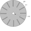
- FIG. 1 is a schematic diagram showing a configuration example of the analysis rotating body 100.
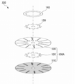
- 2A to 2E are schematic views showing members constituting the analysis rotating body 100 in FIG. 1
- FIG. 2A is a schematic view showing a configuration of the wax print member 110
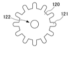
- FIG. 2B is a configuration of the inlet member 120.
- 2C is a schematic diagram showing the configuration of the top cover member 130
- FIG. 2D is a schematic diagram showing the configuration of the inlet cover member 140
- FIG. 2E is a schematic diagram showing the configuration of the laminate mask member 150.
- FIG. 3 is an assembly exploded view of the analysis rotating body 100 of FIG. As shown in FIGS.
- the analysis rotating body 100 includes a wax print member 110 (microchannel member), an inlet member 120, a top cover member 130 (cover member), and an inlet cover member 140 (protective member). ) And the laminated mask member 150 is used at the time of manufacture.
- the wax printing member 110 is a disk-shaped member in which a microchannel 111 is formed by wax printing on a base material made of white paper (for example, commercially available filter paper such as Whatman Filter Paper (trademark)), and has a through hole at the center. 112 is formed.
- white paper for example, commercially available filter paper such as Whatman Filter Paper (trademark)
- Whatman Filter Paper trademark
- the micro channel 111 extends in a radial direction from a position separated from the center of the wax print member 110 to a position inside the outer circumference of the wax print member 110.
- a color change indicator is arranged so that the higher the concentration of the measurement target component, the longer the reaching distance.
- a scale for measuring the reaching distance of the sample solution is formed along the micro channel 111 of the wax print member 110.
- the same type of color change indicator can be arranged in all the micro channels 111, or the micro channels 111 in which different kinds of color change indicators are arranged are formed in a mixed manner. It is possible. When the microchannels 111 in which a plurality of types of color change indicators are arranged are mixedly formed, a plurality of types of analysis can be performed simultaneously.
- the inlet member 120 is a disc-shaped member produced by die-cutting a film, and has a smaller diameter than the wax print member 110.
- a plurality of protrusions 121 are formed on the outer periphery of the inlet member 120, and a through hole 122 is formed at the center.
- the protrusions 121 are respectively formed at positions arranged close to the ends (starting points) on the center side of each microchannel 111 when the protrusions 121 are overlapped with the center of the wax print member 110.
- the top cover member 130 is a disc-shaped member manufactured by die-cutting a film, and has the same outer diameter as the wax print member 110. Further, through holes 131 having the same shape as the micro channels 111 are formed in the top cover member 130 at positions overlapping with the respective micro channels 111 when the top cover member 130 is overlapped with the wax print member 110 so as to be centered. Further, at the end portion on the center side of each through hole 131, a through hole 132 serving as a sample solution supply port is formed, and a through hole 133 is formed at the center.
- the inlet cover member 140 is an annular member formed by die-cutting a film, and has an outer diameter larger than the outer edge of the through hole 132 (specimen solution supply port) of the top cover member 130 and an inner diameter of the top cover.
- the size of the member 130 is the distance to the center of the through hole 132.
- a small semicircular cutout 141 is formed on the inner periphery of the inlet cover member 140 at a position overlapping the through hole 132 when being overlapped with the center of the top cover member 130.
- the laminating mask member 150 is a disc-shaped member that is manufactured by die-cutting a flexible, fixed-thickness paper (such as cooking paper), and is configured to have substantially the same shape as the inlet member 120.
- the laminating mask member 150 is a mask member for preventing the inlet member 120 and the inlet cover member 140 from adhering at the position of the through hole 132 of the top cover member 130 during lamination.
- the protrusion 151 formed on the outer periphery of the laminate mask member 150 is formed slightly smaller than the protrusion 121 of the inlet member 120. With such a configuration, the laminated mask member 150 can be easily taken out after the inlet member 120 is laminated.
- the pattern of the wax print member 110 is printed on an A4 size filter paper or the like by a wax printer.
- the wax print member 110 is heated at 150 ° C. for 3 minutes using a hot plate or the like.
- the wax print member 110 is completed by cutting off the portion of the wax print member 110 on which the pattern is formed.
- the inlet member 120 is manufactured by cutting a film having a thickness of about 100 [ ⁇ m] with a cutting machine.
- the top cover member 130 and the inlet cover member 140 are manufactured by cutting a film having a thickness of about 150 [ ⁇ m] with a cutting machine.
- the laminate mask member 150 is manufactured by cutting a flexible paper (such as cooking paper) having a certain thickness with a cutting machine.
- the wax print member 110 is placed on the film which will be the cover film B (described later) at the bottom, and the inlet member 120 and the top cover member 130 are superposed with their centers aligned in this order, and the first time by the laminator. Laminate.
- the micro-channel 111 of the wax print member 110 and the through hole 131 of the top cover member 130, and the protrusion 121 of the inlet member 120 and the through hole 132 of the top cover member 130 are aligned and laminated.
- through holes are formed at positions corresponding to the through holes 112 of the wax print member 110, the through holes 133 of the top cover member 130, and the through holes 122 of the inlet member 120.
- the portion of the micro channel 111 of the wax print member 110 is opened in the through hole 131 of the top cover member 130, and the protrusion 121 of the inlet member 120 is arranged at the end of the micro channel 111 on the center side.
- the through hole 132 of the top cover member 130 is arranged at the position 121 to form the stack 100A in which the sample solution supply port is formed (see FIG. 3).
- the through holes 131 and 132 of the top cover member 130 are formed independently, and a partition wall made of a film exists between them. The lower part of the partition wall is in contact with the surface of the wax-printed portion of the wax-printed member 110 (the portion adjacent to the end of the microchannel 111 on the center side).
- partition wall contact surface The partition wall of the top cover member 130 and the surface of the wax-printed portion of the wax printing member 110 that is in contact with the partition wall (hereinafter referred to as the “partition wall contact surface”) are connected to the microchannel 111 from the sample solution supply port. It fulfills the function of the valve of the flow path.
- a portion composed of the partition wall of the top cover member 130 and the partition wall contact surface of the wax print member 110 is appropriately referred to as a “valve portion 134” (see FIG. 4 described later).
- the laminate 100A is used as the lowermost layer, and the laminate mask member 150 and the inlet cover member 140 are superposed with their centers aligned in this order, and the second lamination is performed using a laminator.
- the protrusions 151 of the laminating mask member 150 and the through holes 132 of the top cover member 130 are aligned with each other, and the notches 141 of the inlet cover member 140 and the through holes 132 of the top cover member 130 are aligned with each other for lamination. ..
- the protrusion 151 of the laminate mask member 150 is sandwiched between the protrusion 121 of the inlet member 120 and the inlet cover member 140 in the through hole 132 of the top cover member 130. Therefore, it is possible to prevent the inlet cover member 140 from being bonded to the inlet member 120. After that, the laminate mask member 150 is pulled out, and the analysis rotating body 100 shown in FIG. 1 is completed.
- the through hole 132 of the top cover member 130 is used as the supply port for the sample solution, and the flow path of the sample solution connected to the microchannel 111 via the valve section 134 is formed.
- a plurality of microchannels 111 are arranged radially from the rotation center of the analysis rotator 100.
- the sample solution is prevented from flowing out until a certain pressure, and when the certain pressure is exceeded, It has a function of allowing the sample solution to flow out to the microchannel 111.
- the sample solution is supplied to the microchannel at an unexpected timing. Penetration into 111 can be suppressed.
- FIG. 4 is a schematic diagram showing a cross-sectional structure of the microchannel 111 of the analysis rotating body 100. Note that FIG. 4 shows a cross section taken along the line AA ′ in FIG.
- the through hole 132 of the top cover member 130 serves as a supply port for the sample solution, and the sample solution has the protrusion 121 of the inlet member 120, the wax print member 110, and the top cover member 130. And is introduced into a space surrounded by the inlet cover member 140 (hereinafter referred to as “reservoir 100B”).
- the member surrounding the reservoir 100B is made of a hydrophobic material
- the valve portion 134 has a structure in which the top cover member 130 made of a hydrophobic material and the wax-printed portion are in contact with each other. Therefore, in the valve section 134, the sample solution is prevented from flowing out to a certain pressure, and when the pressure exceeds the certain pressure, the sample solution is allowed to flow out.
- the partition wall of the top cover member 130 in the valve portion 134 can prevent the sample solution from flowing out from the surface of the wax print member 110 and entering from the upper surface of the microchannel 111. Further, since the inlet cover member 140 is placed over the valve portion 134, the sample solution is prevented from overflowing from the storage portion 100B and flowing into the microchannel 111 from the upper surface of the top cover member 130. ..
- FIG. 5 is a schematic diagram showing the configuration of the analyzer 1 according to the present invention.
- the analysis device 1 includes a control unit 10 and a rotation unit 20.
- the control unit 10 is configured by an information processing device such as a microcomputer or a PC (Personal Computer), and controls the rotating operation of the rotating unit 20. Specifically, the control unit 10 receives the setting of the rotation speed by the user, and outputs a rotation speed instruction signal (a PWM signal or the like representing a voltage command value) to the rotation unit 20 to determine the rotation speed of the rotation unit 20. Control.
- a rotation speed instruction signal a PWM signal or the like representing a voltage command value
- the rotary unit 20 includes an actuator 21 such as an electric motor.
- the analysis rotating body 100 is installed on the rotation axis of the actuator 21. Then, the rotation unit 20 rotates the actuator 21 at a speed according to the rotation speed instruction signal input from the control unit 10.
- the analyzer 1 configured in this way has the function of the distance detection type ⁇ PADs.
- FIG. 6 is a flowchart showing an example of a procedure for analyzing the sample solution using the analysis rotating body 100.
- the sample solution is analyzed using the rotator for analysis 100
- the sample of 3 [ ⁇ L] is stored in the reservoir 100B.
- the solution is dropped (step S1).
- the actuator 21 is rotated for 30 seconds at 279 [rad / s] (step S2).
- control unit 10 is programmed to accept the dropping of the sample solution or control the rotation of the actuator 21 corresponding to the analysis procedure of FIG. 6, and the above procedure is automatically executed by executing the program. be able to.
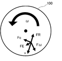
- FIG. 7 is a schematic diagram showing the force acting on the sample solution when the analysis rotating body 100 rotates.
- the sample solution contains a centrifugal force F ⁇ , an Euler force FE, and a Coriolis force Fc.
- the resistance force FR acts.
- the centrifugal force F ⁇ , the Euler force FE, and the Coriolis force Fc are expressed as follows, respectively.
- F ⁇ ⁇ ( ⁇ ⁇ r) (1)
- FE ⁇ (d ⁇ / dt) ⁇ ⁇ (2)
- Fc -2 ⁇ ⁇ v (3)
- ⁇ is the density
- ⁇ is the angular velocity
- r is the radius of gyration
- v is the moving velocity of the sample solution.
- the resistance force FR is considered to be a resistance force mainly due to the fact that the capillary phenomenon of paper acts as a braking force against movement.
- the sample solution reaches a longer distance with the concentration of the measurement target component in the sample solution being higher, starting from the reservoir 100B. That is, the function of the distance detection type ⁇ PADs can be realized while making the movement of the sample solution more rapid. Therefore, according to the analyzer 1, it is possible to shorten the time required to analyze the distance detection type ⁇ PADs.
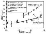
- FIG. 8 is a schematic diagram showing the results of the analysis performed by the analyzer 1 under various conditions.
- the coarseness of the paper W1: Whatman Filter Paper Grade 1
- the coarse paper W4: Whatman Filter Paper Grade 4
- the analysis was performed by changing the rotation speed of the rotating body for analysis 100 in the case where the installation position of the supply port was close to the center (55 [mm]) and the position far from the center was 60 [mm]. The results are shown.
- 3 to 4 [ ⁇ L] of the food dye aqueous solution was dropped into the supply port as a sample solution.
- the rotator 100 for analysis was rotated at different speeds for 45 seconds.
- the flow velocity of the sample solution increases as the roughness of the paper forming the wax print member 110 increases. Further, according to FIG. 8, it can be seen that the flow velocity of the sample solution becomes slower as the dropping position of the sample solution is closer to the center. Further, according to FIG. 8, it can be seen that the slower the rotation speed of the analysis rotator 100, the slower the flow rate of the sample solution.
- FIG. 9 is a schematic diagram showing the results when an analysis was performed with different microchannel sealing properties.
- FIG. 9 shows the results of analysis performed when the through hole 131 of the top cover member 130 is opened and when the through hole 131 is closed (the upper surface is sealed).
- the rotator 100 for analysis was rotated at different speeds for 45 seconds.
- the flow velocity of the sample solution increases as the rotation speed increases, both when the microchannel is closed (Fully-closed) and when it is opened (Open). Recognize. That is, according to FIG. 9, it is understood that substantially the same analysis can be performed when the microchannel is closed and when it is opened. It should be noted that when the microchannel is closed, the drying of the sample solution is hindered, and therefore it is suitable for analyzing a sample having a slow reaction rate, and when the microchannel is opened, the sample solution cannot be dried. Since it is promoted, it is considered to be suitable for analyzing a sample having a fast reaction rate.
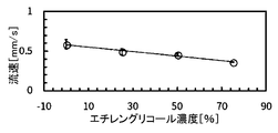
- FIG. 10A and FIG. 10B are schematic diagrams showing the results when analysis is performed by changing the viscosity of the sample solution.
- FIG. 10A shows the relationship between the concentration of ethylene glycol solution and the flow rate
- FIG. 10B shows the result of ethylene glycol solution.
- the relationship between the kinematic viscosity and the flow velocity is shown.
- 10A and 10B show the results of analysis using ethylene glycol solutions of various concentrations as the sample solution.
- 3 [ ⁇ L] of ethylene glycol solution of various concentrations colored with a food dye was dropped as a sample solution into the supply port.
- the rotating body for analysis 100 was rotated at 279 [rad / s] for 45 seconds.
- ⁇ 1 is the dynamic viscosity of the measurement target liquid
- ⁇ 0 is the dynamic viscosity of the control liquid (water)
- t 1 is the moving time required for the reference movement distance of the measurement target liquid
- t 0 is the control liquid (water)
- u1 is the moving speed of the liquid to be measured
- u0 is the moving speed of the control liquid (water).
- FIG. 11 is a schematic diagram showing the result when the analysis is performed by changing the fiber direction of the paper in the microchannel.
- the fiber direction of the paper in the microchannel is changed between the winding direction (MD (Machine Direction) direction) of the roller in the manufacturing process and the direction (CD (Cross Direction) direction) intersecting with the winding direction.
- MD Machine Direction
- CD Cross Direction
- the result of the analysis is shown.
- the fiber direction of commercially available paper includes a winding direction (MD direction) of a roller in a manufacturing process and a direction intersecting with the winding direction (CD direction). Due to these differences, the liquid permeation rate due to a capillary phenomenon changes. It will be done. On the other hand, according to FIG. 11, it can be seen that there is no significant difference in the flow rate of the sample solution regardless of whether the fiber direction of the paper in the microchannel is the MD direction or the CD direction. That is, when the analysis method of the present invention is used, it is considered that the difference in the moving speed of the sample solution between the MD direction and the CD direction is relatively compressed by the centrifugal force, and the influence on the analysis result is suppressed.
- FIG. 12 is a schematic diagram showing the result when the analysis is performed by changing the rotation speed of the analysis rotating body 100.
- the analysis shown in FIG. 12 first, as a sample solution, 3 [ ⁇ L] of the food dye aqueous solution was dropped into the supply port. Next, the rotator 100 for analysis was rotated at different speeds for 45 seconds. According to FIG. 12, it can be seen that the faster the rotation speed, the longer the reaching distance of the sample solution. That is, according to FIG. 12, it is understood that the rotation speed of the analysis rotator 100 should be taken into consideration when performing analysis based on the reach distance of the sample solution.
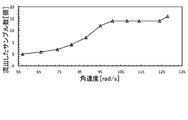
- FIG. 13 is a schematic diagram showing the relationship between the rotational speed (angular velocity) of the analytical rotator 100 and the outflow state of the sample solution from the valve portion 134.
- FIG. 13 shows the result of observing whether or not the sample solution flows out by changing the rotational speed (angular velocity) of the analysis rotary body 100 with 16 valve parts 134 as targets (samples).
- the rotation speed of the analytical rotator 100 is equal to or lower than the predetermined value
- the sample solution does not flow out from all of the valve portions 134, and the sample solution is discharged from some of the valve portions 134 at the rotation speed equal to or higher than the predetermined value. You can see that it will be leaked.
- the sample solution flows out through all the valve parts 134. That is, by installing the valve unit 134, it is possible to control so that the sample solution does not flow out to the microchannel 111 unless the analysis rotating body 100 is rotated.
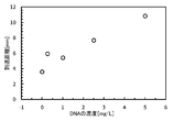
- FIG. 14 is a schematic diagram which shows the result at the time of analyzing DNA (double-stranded DNA) using the rotating body 100 for an analysis.
- DNA double-stranded DNA
- FIG. 14 first, 5.5 [ ⁇ L] of a DNA sample solution was dropped as a sample solution into the supply port. Next, the rotator 100 for analysis was rotated for 30 seconds at 260 [rad / s] after 60 seconds when the position where the tip of the sample solution reached reached about 14 [mm]. According to FIG. 14, even in the analysis of DNA, the reaching distance of the sample solution changes depending on the concentration of DNA, and it can be understood that analysis can be performed by the analyzer 1.
- the rotating body for analysis 100 is configured such that the bottom surface of the storage section 100B is wax-printed and the valve section 134 is provided. On the other hand, it is possible to make the structure of the analysis rotating body 100 simpler.
- FIG. 15 is a schematic view showing another configuration example of the analysis rotating body 100.
- the analysis rotating body 100 of the present modified example includes a wax print member 110 and a top cover member 130.
- the wax print member 110 is a disk-shaped member in which a microchannel 111 is formed by wax printing on a base material made of white paper (for example, commercially available filter paper such as Whatman Filter Paper (trademark)), and has a through hole in the center. 112 is formed.
- white paper for example, commercially available filter paper such as Whatman Filter Paper (trademark)
- the micro channel 111 extends in a radial direction from a position separated from the center of the wax print member 110 to a position inside the outer circumference of the wax print member 110.
- a circular supply region 113 for dropping the sample solution is formed at the end of the microchannel 111 on the center side.
- the supply region 113 is a portion of the wax print member 110 where the paper is exposed, and is directly connected to the microchannel 111. Therefore, the function of the valve portion 134, which is different from the analyzing rotary body 100 of FIG. 1, is not mounted on the analyzing rotary body 100 of the present modification.
- a color change indicator is arranged so that the higher the concentration of the measurement target component, the longer the reaching distance.
- a scale for measuring the reaching distance of the sample solution is formed along the micro channel 111 of the wax print member 110.
- the top cover member 130 is an annular member formed by stamping a film, and has the same outer diameter as the wax print member 110. Further, the inner diameter of the top cover member 130 is set to a length that coincides with the end portion on the center side of each microchannel 111 when the top cover member 130 and the wax print member 110 are overlapped with the center aligned. Therefore, the supply area 113 of the wax print member 110 is not covered with the top cover member 130.
- the microchannels 111 of the analytical rotating body 100 of the present modified example are covered with the top cover member 130. Further, the top cover member 130 has a through hole 133 formed at the center. Note that, also in the top cover member 130 in the present modification example, the through hole 131 having the same shape as the microchannel 111 may be formed as in the above-described embodiment.
- the rotator for analysis 100 shown in FIG. 15 can be manufactured by manufacturing the wax print member 110 and the top cover member 130, then stacking them with their centers aligned and laminating with a laminator.
- the rotating body for analysis 100 configured as described above has a structure in which the supply region 113 of the wax print member 110 is used as a supply port for the sample solution, and a flow path for the sample solution that is directly connected to the microchannel 111 from the supply region 113 is formed. Have. Further, in the analysis rotator 100, a plurality of microchannels 111 are arranged radially from the rotation center of the analysis rotator 100.
- FIG. 16 is a schematic diagram showing a cross-sectional structure of the microchannel 111 of the analytical rotator 100 of the present modification. Note that FIG. 16 shows a BB ′ cross section in FIG. 15. As shown in FIG. 16, in the analytical rotator 100 of the present modification, the supply region 113 of the wax print member 110 and the microchannel 111 are flush with each other, and the sample solution dropped in the supply region 113 is It can penetrate into the microchannels 111. The top surface of the microchannel 111 is covered with the top cover member 130. With such a structure, the rotating body for analysis 100 that can be used in the analyzing method of the present invention can be manufactured with a simple manufacturing process and structure.
- the rotating body for analysis 100 of this modification can be used.
- the analysis rotator 100 of the present modification can be used in the analysis device 1 in the above-described embodiment, similarly to the analysis rotator 100 shown in FIG. 1.
- FIG. 17 is a flowchart showing an example of a procedure for analyzing a sample solution using the rotator for analysis 100.
- the sample solution is analyzed using the rotator for analysis 100
- the sample of 7 [ ⁇ L] is supplied to the supply region 113.
- the solution is dropped (step S11).
- it waits for the penetration of the sample solution for 60 seconds (step S12).
- the actuator 21 is rotated for 30 seconds at 279 [rad / s] (step S13).
- control unit 10 is programmed to receive the dropping of the sample solution corresponding to the analysis procedure of FIG. 17, wait for permeation, or control the rotation of the actuator 21, and the above procedure automatically proceeds by executing the program. Can be configured.
- FIG. 18 is a schematic diagram showing another configuration example of the analysis rotating body 100.
- 19 is an assembly exploded view of the analysis rotating body of FIG. 18, and
- FIG. 20 is a schematic diagram showing a configuration example of a main part of the analysis rotating body 100.
- the analysis rotating body 100 of the present modified example includes a wax print member 110, an inlet member 120, and a top cover member 130.
- the wax print member 110 is a disc-shaped member in which a microchannel 111 is formed by wax printing on a base material made of white paper (for example, commercially available filter paper such as Whatman Filter Paper (trademark)), and has a through hole at the center. 112 is formed. Further, in the wax print member 110 of the present modification, the outer peripheral side end of the microchannel 111 is bent in the circumferential direction and is connected to the absorption pad region 111a (sample solution receiving part).
- the absorption pad region 111a is a region for absorbing and receiving the sample solution that has reached the outer peripheral side end of the microchannel 111.
- the portions other than the portions that become the microchannels 111 and the absorption pad regions 111a are covered with wax that is a hydrophobic material, and the wax has penetrated to the back surface by heat treatment.
- the micro channel 111 extends in a radial direction from a position separated from the center of the wax print member 110 to a position inside the outer circumference of the wax print member 110.
- a chamber 114 (reservoir) having a shape such as a circle or a square for storing the sample solution is formed at the end of the microchannel 111 on the center side.
- the chamber 114 is a portion in which the wax-printed portion of the wax-printed member 110 is die-cut to form a through hole, and by disposing the cover film B at the bottom, it is possible to store the sample solution. Becomes Further, in the micro channel 111, a color change indicator is arranged so that the higher the concentration of the measurement target component, the longer the reaching distance. In addition, a scale for measuring the reaching distance of the sample solution is formed along the micro channel 111 of the wax print member 110.
- the inlet member 120 is a disc-shaped member produced by die-cutting a film, and has a smaller diameter than the wax print member 110.
- a through hole 122 is formed at the center of the inlet member 120, and a plurality of inlet holes 123 for supplying the sample solution to the chamber 114 are formed around the through hole 122.
- the inlet holes 123 are respectively formed at positions overlapping the center-side ends of the chambers 114 when the center is overlapped with the wax print member 110.
- the top cover member 130 is a disc-shaped member manufactured by die-cutting a film, and has the same outer diameter as the wax print member 110. Further, in the top cover member 130, through holes 135 having the same shape as the chamber 114 are formed at positions overlapping with the chambers 114 when the wax print member 110 is overlapped with the center thereof aligned. The through hole 135 constitutes a part of the side wall of the chamber 114 by being overlapped with the chamber 114. A through hole 133 is formed at the center of the top cover member 130.
- FIG. 21 is a schematic diagram showing the structure of the chamber 114.
- the chamber 114 is formed as a space surrounded by the cover film B at the bottom, the wax print member 110, the top cover member 130, and the inlet member 120, and the sample solution is supplied from the inlet hole 123 of the inlet member 120. It has a structure to be supplied.
- the chamber 114 can be formed in various planar shapes according to the amount of the sample solution to be stored and the like.
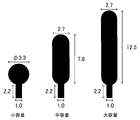
- FIG. 22 is a schematic diagram showing an example of the planar shape of the chamber 114. As shown in FIG.
- the chamber 114 when the chamber 114 is formed, it can have a planar shape such as a circular shape or a rectangular shape when viewed from the top, and the capacity of the chamber 114 also depends on the type of the sample solution and the required storage amount. It can be appropriately selected. In FIG. 22, three types of chambers 114 of small volume, medium volume and large volume are shown. The numerical values in FIG. 22 represent the size of the chamber 114 (unit is millimeter).
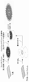
- FIG. 23 is a schematic diagram showing a method of manufacturing the analytical rotator 100 in the present modification.
- the pattern of the wax print member 110 is printed on a filter paper of A4 size or the like by a wax printer.
- the wax print member 110 is heated at 150 ° C. for 90 seconds using a hot plate or the like.
- the wax print member 110 is completed by cutting off the portion of the wax print member 110 on which the pattern is formed.
- the inlet member 120 and the top cover member 130 are manufactured by cutting a film having a thickness of about 150 [ ⁇ m] with a cutting machine.
- the wax print member 110 is placed on the film which will be the cover film B at the bottom, and the top cover member 130 and the inlet member 120 are superposed with their centers aligned in this order, and laminated by a laminator.
- the chamber 114 of the wax print member 110, the through hole 135 of the top cover member 130, and the inlet hole 123 of the inlet member 120 are aligned and laminated.
- through holes are formed at positions corresponding to the through holes 112 of the wax print member 110, the through holes 133 of the top cover member 130, and the through holes 122 of the inlet member 120.
- the bottom of the chamber 114 of the wax print member 110 is closed by the cover film B, the through hole 135 of the top cover member 130 is overlapped with the chamber 114, and the inlet member is provided at the center side end of the chamber 114.
- the inlet rotor 123 of 120 is arranged to form the analytical rotator 100 in which the sample solution supply port is formed.
- the through hole 135 of the top cover member 130 is formed inside the end of the wax print member 110 on the center side of the microchannel 111, and a partition wall made of a film is provided between the chamber 114 and the microchannel 111. (Side wall on the outer peripheral side of the through hole 135) exists.
- the lower part of the partition wall is in contact with the surface of the wax-printed portion of the wax-printed member 110 (the portion adjacent to the end of the microchannel 111 on the center side).
- the side wall of the top cover member 130 on the outer peripheral side of the through hole 135 and the surface of the wax-printed portion of the wax printing member 110 (partition contact surface) that is in contact therewith are connected to the microchannel 111 from the supply port of the sample solution.
- the valve portion 134 functions as a valve of the flow path.
- the rotator for analysis 100 uses the inlet hole 123 of the inlet member 120 as a supply port for the sample solution, can store the sample solution in the chamber 114, and can be stored in the microchannel 111 via the valve section 134. It has a structure in which a flow path of a connected sample solution is formed. Further, in the analysis rotator 100, a plurality of microchannels 111 are arranged radially from the rotation center of the analysis rotator 100.
- the sample solution is prevented from flowing out until a certain pressure, and when the certain pressure is exceeded, It has a function of allowing the sample solution to flow out to the microchannel 111.
- the sample solution may permeate the microchannel 111 at an unexpected timing. Can be suppressed.
- the outer peripheral side end of the microchannel 111 is bent in the circumferential direction and is connected to the absorption pad region 111a.
- the analysis of the sample solution can be performed using the analyzer 1 shown in FIG.
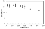
- FIG. 24 is a schematic diagram showing the relationship between the rotation speed of the rotator for analysis 100 and the coloring distance of the microchannel 111. Note that FIG. 24 shows the evaluation results using the nickel standard solution and the nickel coloration indicator DMG (dimethylglyoxime) (the same applies in the following verification).
- a predetermined speed here, 220 [rad / s]
- the rotation speed exceeds the predetermined speed
- the coloration distance is increased. You can see that is shortened. This means that if the rotation speed of the analysis rotator 100 becomes excessively high, leakage of the sample solution will occur, and an appropriate analysis result cannot be obtained.
- FIG. 25 is a schematic diagram showing the relationship between the shape of the chamber 114 and the coloration distance of the microchannel 111. According to FIG. 25, even if the rotator 100 for analysis is rotated for a certain period of time or more, no extension of the coloration distance is observed, so that the time independence of the coloration reaction can be confirmed. As a result, the user does not need to measure the time of color reaction, and a POCT (Point of Care Testing) device with high user convenience can be realized.
- POCT Point of Care Testing
- FIG. 26 is a schematic diagram showing the relationship between the weighing amount of the chamber 114 (or the supply amount of the sample solution) and the coloring distance of the microchannel 111.
- the cases shown by numbers indicate the case where the sample solution of the amount fixed by the micropipette is supplied.
- the reproducibility of the analysis result similar to that of the micropipette was obtained even when the chamber 114 of various weighings of the analysis rotating body 100 was used, and the weighing ability of the chamber 114 was confirmed.
- expert knowledge is required when using, and it is possible to control the supply volume of the sample solution without the need for expensive micropipettes, and to provide an analytical rotary body with performance for actual use cases. 100 can be realized.
- FIG. 27 is a schematic diagram showing the results of nickel ion quantitative measurement using the rotating body for analysis 100. Note that FIG. 27 shows the relationship between the nickel ion concentration and the coloration distance of the microchannel 111 for each of the three types of chamber 114 shapes shown in FIG. Further, FIG. 28 is a schematic diagram showing a coloration state of the micro channel 111 in the case of the measurement result shown in FIG. According to FIG. 28, when the measurement of FIG. 27 is performed, a color boundary line (the position of the pin icon) appears at a position corresponding to the nickel concentration, and it can be seen that nickel was successfully measured.
- a color boundary line the position of the pin icon
- the analysis device 1 includes the analysis rotating body 100, the actuator 21, and the control unit 10.
- the microchannels 111 made of a hydrophilic material are formed along the radial direction.
- the actuator 21 rotates the rotating body 100 for analysis.
- the control unit 10 controls the rotation of the actuator 21.
- the microchannel 111 has an indicator that indicates the concentration of the measurement target component according to the reaching distance of the sample solution.
- the flow rate of the sample solution can be increased while maintaining contact between the hydrophilic material (paper or the like) having the indicator and the sample solution, and the analysis can be performed more quickly. Therefore, the time required to analyze the distance detection type ⁇ PADs can be shortened.
- the analysis rotating body 100 includes a wax print member 110 and a top cover member 130.
- Wax print member 110 includes microchannels 111, and a hydrophobic material is arranged in a portion other than microchannels 111.
- the top cover member 130 constitutes a cover member that covers the microchannel member.
- a hydrophobic material can be disposed on the wax print member 110 made of a hydrophilic material to form the microchannel 111, and the wax print member 110 and the top cover member 130 are integrated for analysis.
- the rotating body 100 can be configured. Therefore, the micro-channel 111 can be designed easily and flexibly, and the rotating body for analysis can be easily manufactured.
- a portion where the hydrophilic material is exposed at the end portion on the center side of the microchannel 111 serves as a sample solution supply region 113.
- the microchannel 111 can be realized with a simple configuration.
- the control unit 10 waits for the sample solution to permeate the hydrophilic material for a set time, and then rotates the actuator 21 to move the hydrophilic material to the hydrophilic material.
- the sample solution is analyzed by moving the permeated sample solution in the microchannel 111. With this, it is possible to realize the analyzer 1 suitable for the case where the analysis is performed promptly after supplying the sample solution to the supply region 113.
- the analysis rotating body 100 includes a storage section 100B and a valve section 134.
- the reservoir 100B is configured such that the end of the microchannel 111 on the center side is surrounded by the hydrophobic material.
- the valve unit 134 is installed between the storage unit 100B and the microchannel 111 to adjust the outflow of the sample solution.
- the analysis rotator 100 includes an inlet cover member 140.
- the inlet cover member 140 suppresses the outflow of the sample solution overflowing from the storage section 100B. Accordingly, even when the sample solution is stored in the storage section 100B, it is possible to prevent the sample solution from overflowing and flowing out.
- the control unit 10 rotates the actuator after the sample solution is supplied to the storage section to cause the sample solution to flow out from the valve section 134 and permeate the sample solution into the end of the microchannel 111 on the center side.
- the sample solution is analyzed by moving the permeated sample solution in the microchannel 111, whereby after the sample solution is supplied to the supply region 113, the sample solution is waited without permeating the sample solution into the hydrophilic material and then analyzed. It is possible to realize the analyzer 1 suitable for performing the above.
- the analysis rotator 100 includes an absorption pad region 111a.
- the absorption pad region 111a receives the sample solution that has reached the outer peripheral side end of the microchannel 111.
- the absorption pad region 111a receives the sample solution that has reached the outer peripheral side end of the microchannel 111.
- the sample solution that has reached the outer peripheral side end of the microchannel 111 can be absorbed, it is possible to prevent the excess sample solution from staying in the microchannel 111, and to more appropriately store the sample solution. Analysis can be performed.
- the analysis method includes a rotation step and a reaction step.
- the rotating step the sample solution is supplied to the end of the microchannel 111 on the center side of the analytical rotator 100 in which the microchannels 111 made of a hydrophilic material are formed in the radial direction. 100 is rotated.
- the indicator solution in which the concentration of the component to be measured is indicated according to the reaching distance of the sample solution in the microchannel 111, reacts with the sample solution.
- the flow rate of the sample solution can be increased while maintaining contact between the hydrophilic material (paper or the like) having the indicator and the sample solution, and the analysis can be performed more quickly. Therefore, the time required to analyze the distance detection type ⁇ PADs can be shortened.
- the microchannels 111 made of a hydrophilic material are formed along the radial direction, and the indicator showing the concentration of the measurement target component according to the reach distance of the sample solution.
- the sample solution moves in the microchannel 111 by being rotated, and the sample solution and the indicator react with each other.
- the flow rate of the sample solution can be increased while maintaining contact between the hydrophilic material (paper or the like) having the indicator and the sample solution, and the analysis can be performed more quickly. Therefore, it is possible to realize the analysis rotating body capable of shortening the time required for the analysis of the distance detection type ⁇ PADs.
- the analysis rotator 100 may have a detailed structure different from that of the analysis rotator 100 described above as long as microchannels extending in the radial direction from the center of rotation are formed.
- the valve part 134 is formed between the storage part 100B and the microchannel 111, but a structure without a valve may be used. That is, the structure of the rotating body for analysis 100 can be variously changed according to the characteristics of the sample to be analyzed, the analysis method, and the like.
- the rotating body for analysis 100 is described as having a disk-shaped configuration, but the present invention is not limited to this. That is, the analysis rotating body 100 may have a shape other than the disk shape as long as it has a symmetrical shape with respect to the center of rotation.
- the present invention can be implemented by appropriately combining the examples described in the above embodiments.
- the absorbent pad 111a shown in the modified example 2 may be provided in the analysis rotating body 100 shown in FIG. 1 or 15.
- the processing for control in the above-described embodiment can be executed by either hardware or software. That is, it is sufficient that the analysis apparatus 1 has a function capable of executing the above-described processing, and the functional configuration and hardware configuration for realizing this function are not limited to the above-described example.
- 1 analysis device 10 control unit, 20 rotation unit, 21 actuator, 100 analysis rotating body, 110 wax print member, 111 microchannel, 111a absorption pad area, 112, 122, 131, 132, 133, 135 through hole, 113 Supply area, 114 chamber, 120 inlet member, 121, 151 protruding part, 123 inlet hole, 130 top cover member, 134 valve part, 140 inlet cover member, 141 notch, 150 laminate mask member, 100A laminated body, 100B storage part , B cover film
Landscapes
- Physics & Mathematics (AREA)
- Chemical & Material Sciences (AREA)
- General Health & Medical Sciences (AREA)
- Health & Medical Sciences (AREA)
- Life Sciences & Earth Sciences (AREA)
- Analytical Chemistry (AREA)
- Biochemistry (AREA)
- General Physics & Mathematics (AREA)
- Immunology (AREA)
- Pathology (AREA)
- Chemical Kinetics & Catalysis (AREA)
- Plasma & Fusion (AREA)
- Engineering & Computer Science (AREA)
- Automatic Analysis And Handling Materials Therefor (AREA)
- Investigating Or Analysing Materials By The Use Of Chemical Reactions (AREA)
Abstract
La présente invention vise à réduire le temps nécessaire pour une analyse avec des μPAD basés sur une détection de distance. À cet effet, le dispositif analytique 1 comprend un corps rotatif 100 pour une analyse, un actionneur 21, et une unité de commande 10. Le corps rotatif 100 pour une analyse possède, formé le long d'une direction radiale de celui-ci, un microcanal 111 constitué d'un matériau hydrophile. L'actionneur 21 fait tourner le corps rotatif 100 pour une analyse. L'unité de commande 10 commande la rotation de l'actionneur 21. Le microcanal 111 possède un indicateur qui indique la concentration d'un constituant à mesurer en fonction de la distance atteinte par une solution d'échantillon.
Applications Claiming Priority (2)
| Application Number | Priority Date | Filing Date | Title |
|---|---|---|---|
| JP2018-209278 | 2018-11-06 | ||
| JP2018209278A JP2022017614A (ja) | 2018-11-06 | 2018-11-06 | 分析装置、分析方法及び分析用回転体 |
Publications (1)
| Publication Number | Publication Date |
|---|---|
| WO2020095914A1 true WO2020095914A1 (fr) | 2020-05-14 |
Family
ID=70611969
Family Applications (1)
| Application Number | Title | Priority Date | Filing Date |
|---|---|---|---|
| PCT/JP2019/043345 Ceased WO2020095914A1 (fr) | 2018-11-06 | 2019-11-05 | Dispositif analytique, procédé analytique et corps rotatif pour analyse |
Country Status (2)
| Country | Link |
|---|---|
| JP (1) | JP2022017614A (fr) |
| WO (1) | WO2020095914A1 (fr) |
Citations (9)
| Publication number | Priority date | Publication date | Assignee | Title |
|---|---|---|---|---|
| JPS5175596A (fr) * | 1974-12-18 | 1976-06-30 | Becton Dickinson Co | |
| JP2002202310A (ja) * | 2000-10-27 | 2002-07-19 | Morinaga Milk Ind Co Ltd | 物質の検出試薬及び検出方法 |
| JP2003524145A (ja) * | 1998-05-08 | 2003-08-12 | ユィロス・アクチボラグ | 微流体装置 |
| JP2006138652A (ja) * | 2004-11-10 | 2006-06-01 | Matsushita Electric Ind Co Ltd | 分析装置 |
| JP2008525798A (ja) * | 2004-12-23 | 2008-07-17 | キンバリー クラーク ワールドワイド インコーポレイテッド | マイクロ流体検定デバイス |
| WO2012105721A1 (fr) * | 2011-02-05 | 2012-08-09 | 野地 澄晴 | Puce tridimensionnelle de microdiagnostic à base de papier |
| US20130302830A1 (en) * | 2010-06-17 | 2013-11-14 | Rajesh K. Mehra | Rotors for immunoassays |
| JP2016045200A (ja) * | 2014-08-25 | 2016-04-04 | ゼロックス コーポレイションXerox Corporation | 用紙ベースのセンサのロバストな比色分析処理方法 |
| WO2018170572A1 (fr) * | 2017-03-23 | 2018-09-27 | Fundação Oswaldo Cruz | Dispositif de diagnostic à symétrie radiale de type à flux latéral et système de lecture d'un dispositif de diagnostic à symétrie radiale de type à flux latéral |
-
2018
- 2018-11-06 JP JP2018209278A patent/JP2022017614A/ja active Pending
-
2019
- 2019-11-05 WO PCT/JP2019/043345 patent/WO2020095914A1/fr not_active Ceased
Patent Citations (9)
| Publication number | Priority date | Publication date | Assignee | Title |
|---|---|---|---|---|
| JPS5175596A (fr) * | 1974-12-18 | 1976-06-30 | Becton Dickinson Co | |
| JP2003524145A (ja) * | 1998-05-08 | 2003-08-12 | ユィロス・アクチボラグ | 微流体装置 |
| JP2002202310A (ja) * | 2000-10-27 | 2002-07-19 | Morinaga Milk Ind Co Ltd | 物質の検出試薬及び検出方法 |
| JP2006138652A (ja) * | 2004-11-10 | 2006-06-01 | Matsushita Electric Ind Co Ltd | 分析装置 |
| JP2008525798A (ja) * | 2004-12-23 | 2008-07-17 | キンバリー クラーク ワールドワイド インコーポレイテッド | マイクロ流体検定デバイス |
| US20130302830A1 (en) * | 2010-06-17 | 2013-11-14 | Rajesh K. Mehra | Rotors for immunoassays |
| WO2012105721A1 (fr) * | 2011-02-05 | 2012-08-09 | 野地 澄晴 | Puce tridimensionnelle de microdiagnostic à base de papier |
| JP2016045200A (ja) * | 2014-08-25 | 2016-04-04 | ゼロックス コーポレイションXerox Corporation | 用紙ベースのセンサのロバストな比色分析処理方法 |
| WO2018170572A1 (fr) * | 2017-03-23 | 2018-09-27 | Fundação Oswaldo Cruz | Dispositif de diagnostic à symétrie radiale de type à flux latéral et système de lecture d'un dispositif de diagnostic à symétrie radiale de type à flux latéral |
Also Published As
| Publication number | Publication date |
|---|---|
| JP2022017614A (ja) | 2022-01-26 |
Similar Documents
| Publication | Publication Date | Title |
|---|---|---|
| Noh et al. | Fluidic timers for time-dependent, point-of-care assays on paper | |
| Martinez et al. | Programmable diagnostic devices made from paper and tape | |
| US11835536B2 (en) | Device and method for qualitative and quantitative analysis of heavy metals utilizing rotary disc system | |
| US20210220822A1 (en) | Passive pumps for microfluidic devices | |
| US11673138B2 (en) | Measurement of an analyte with a cartridge | |
| EP1644184A2 (fr) | Circuits de fluides et procedes et appareil d'utilisation d'echantillons de sang entier dans des analyses colorimetriques | |
| WO2020095914A1 (fr) | Dispositif analytique, procédé analytique et corps rotatif pour analyse | |
| Vereshchagina et al. | Multi-material paper-disc devices for low cost biomedical diagnostics | |
| JP2019132587A (ja) | 分析用トレー | |
| JPH0882590A (ja) | 試料セル保持部材 | |
| Li | Development of a microfluidic fluorescence immunosensor for Point-of-Care diagnostics |
Legal Events
| Date | Code | Title | Description |
|---|---|---|---|
| 121 | Ep: the epo has been informed by wipo that ep was designated in this application |
Ref document number: 19883058 Country of ref document: EP Kind code of ref document: A1 |
|
| NENP | Non-entry into the national phase |
Ref country code: DE |
|
| 122 | Ep: pct application non-entry in european phase |
Ref document number: 19883058 Country of ref document: EP Kind code of ref document: A1 |
|
| NENP | Non-entry into the national phase |
Ref country code: JP |