WO2020095914A1 - 分析装置、分析方法及び分析用回転体 - Google Patents
分析装置、分析方法及び分析用回転体 Download PDFInfo
- Publication number
- WO2020095914A1 WO2020095914A1 PCT/JP2019/043345 JP2019043345W WO2020095914A1 WO 2020095914 A1 WO2020095914 A1 WO 2020095914A1 JP 2019043345 W JP2019043345 W JP 2019043345W WO 2020095914 A1 WO2020095914 A1 WO 2020095914A1
- Authority
- WO
- WIPO (PCT)
- Prior art keywords
- sample solution
- analysis
- microchannel
- rotating body
- rotator
- Prior art date
- Legal status (The legal status is an assumption and is not a legal conclusion. Google has not performed a legal analysis and makes no representation as to the accuracy of the status listed.)
- Ceased
Links
Images


Classifications
-
- G—PHYSICS
- G01—MEASURING; TESTING
- G01N—INVESTIGATING OR ANALYSING MATERIALS BY DETERMINING THEIR CHEMICAL OR PHYSICAL PROPERTIES
- G01N21/00—Investigating or analysing materials by the use of optical means, i.e. using sub-millimetre waves, infrared, visible or ultraviolet light
- G01N21/75—Systems in which material is subjected to a chemical reaction, the progress or the result of the reaction being investigated
- G01N21/77—Systems in which material is subjected to a chemical reaction, the progress or the result of the reaction being investigated by observing the effect on a chemical indicator
-
- G—PHYSICS
- G01—MEASURING; TESTING
- G01N—INVESTIGATING OR ANALYSING MATERIALS BY DETERMINING THEIR CHEMICAL OR PHYSICAL PROPERTIES
- G01N35/00—Automatic analysis not limited to methods or materials provided for in any single one of groups G01N1/00 - G01N33/00; Handling materials therefor
-
- G—PHYSICS
- G01—MEASURING; TESTING
- G01N—INVESTIGATING OR ANALYSING MATERIALS BY DETERMINING THEIR CHEMICAL OR PHYSICAL PROPERTIES
- G01N37/00—Details not covered by any other group of this subclass
Definitions
- the present invention relates to an analyzer for analyzing a sample, an analysis method, and a rotating body for analysis.
- ⁇ PADs microfluidic Paper-based Analytical Devices
- ⁇ PADs is a technique for analyzing a sample using the liquid transport capacity of paper. Specifically, in ⁇ PADs, a hydrophobic paper such as wax is patterned into a desired shape by using a filter paper made of hydrophilic cellulose as a substrate material.
- the hydrophilic portion derived from the filter paper functions as a microchannel, by designing the device design according to the amount of the sample solution and the number of components to be measured, an analytical device suitable for the purpose can be manufactured inexpensively and easily.
- a sample solution is allowed to react with an indicator, and a measuring device such as a camera or a scanner is used to measure the intensity or change in color of the indicator, or the higher the concentration of the component to be measured, the longer the color is.
- a device distance detection type ⁇ PADs for reading the coloration distance by arranging an indicator.
- the measurement data may vary due to individual differences between the measuring devices and ambient light at the shooting location (reproducibility degradation). Is a problem.
- the distance detection type ⁇ PADs do not require a special reading device, and the desired measurement target component can be measured by visually reading the reaching point of the indicator coloration distance.
- Distance detection-type ⁇ PADs have the great merit of being able to intuitively analyze the concentration of the measurement target component and being less likely to cause reading errors for each measurer, and having a practical and user-friendly device concept. It is considered to be more useful. Note that the technology regarding ⁇ PADs is described in Non-Patent Document 1, for example.
- the ⁇ PADs are microfluidic devices, it is necessary for the sample solution to move in a predetermined flow path. Although it is excellent in that liquid can be transported without the need for an external device, the liquid transport speed by paper is slow, and the flow rate of the sample solution greatly affects the analysis time required for the entire measurement. Further, even after reaching the analysis zone of the flow channel, a drying step is required for stabilizing the color intensity obtained depending on the device. As a result, in a typical example, even a simple measuring device requires 20 to 30 minutes as a total measuring time, which is a shackle in performing a quick analysis. On the other hand, in ⁇ PADs, attempts have been made to improve the flow rate of the sample solution.
- a pseudo-capillary tube having a pore size larger than the characteristic of the capillary tube of paper is made, and the sample solution is filled in the capillary tube.
- the distance detection type ⁇ PADs it is premised that the paper on which the indicator is placed and the sample solution are in contact with each other, and as described above, the structure in which the sample solution passes through the pseudo capillary is appropriate. Analysis cannot be performed. As described above, in the conventional technique, it is difficult to reduce the time required for analysis of the distance detection type ⁇ PADs.
- the present invention is to shorten the time required for analysis of distance detection type ⁇ PADs.
- the analysis device of one embodiment of the present invention comprises A rotating body for analysis in which microchannels made of a hydrophilic material are formed along the radial direction, An actuator that rotates the analysis rotating body, A control unit for controlling the rotation of the actuator, Equipped with The microchannel is characterized in that it has an indicator showing the concentration of the component to be measured according to the reaching distance of the sample solution.
- FIG. 9 is a schematic diagram showing a cross-sectional structure of a microchannel of a rotating body for analysis of Modification 1.
- FIG. It is a flow chart which shows an example of the procedure which analyzes a sample solution using a rotating body for analysis.
- FIG. 19 is an assembly exploded view of the analysis rotating body of FIG. 18. It is a schematic diagram which shows the structural example of the principal part of the rotation body for analysis. It is a schematic diagram which shows the structure of a chamber. It is a schematic diagram which shows the planar shape example of a chamber.
- FIG. 9 is a schematic diagram showing a method of manufacturing an analysis rotating body in Modification 2; It is a schematic diagram which shows the relationship between the rotation speed of the rotator for analysis, and the coloring distance of a microchannel. It is a schematic diagram which shows the relationship between the shape of a chamber and the coloring distance of a microchannel.
- FIG. 28 is a schematic diagram showing a coloration state of microchannels in the case of the measurement results shown in FIG. 27.
- the microchannel in which the paper having the color change indicator is arranged in the flow path of the sample solution is formed on the surface of the rotator for analysis made of a flat plate (disk or the like). Then, after supplying the sample solution to the center side of the microchannel, the speed of the sample solution passing through the microchannel is increased by utilizing the centrifugal force by rotating the rotator for analysis.
- the analysis method according to the present invention it is possible to increase the flow rate of the sample solution while maintaining contact between the paper having the color change indicator and the sample solution in the distance detection type ⁇ PADs, and to perform the analysis more quickly. You can That is, with the analysis method according to the present invention, the time required for analysis of the distance detection type ⁇ PADs can be shortened.
- An embodiment of the present invention will be specifically described below.
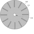
- FIG. 1 is a schematic diagram showing a configuration example of the analysis rotating body 100.
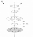
- 2A to 2E are schematic views showing members constituting the analysis rotating body 100 in FIG. 1
- FIG. 2A is a schematic view showing a configuration of the wax print member 110
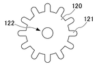
- FIG. 2B is a configuration of the inlet member 120.
- 2C is a schematic diagram showing the configuration of the top cover member 130
- FIG. 2D is a schematic diagram showing the configuration of the inlet cover member 140
- FIG. 2E is a schematic diagram showing the configuration of the laminate mask member 150.
- FIG. 3 is an assembly exploded view of the analysis rotating body 100 of FIG. As shown in FIGS.
- the analysis rotating body 100 includes a wax print member 110 (microchannel member), an inlet member 120, a top cover member 130 (cover member), and an inlet cover member 140 (protective member). ) And the laminated mask member 150 is used at the time of manufacture.
- the wax printing member 110 is a disk-shaped member in which a microchannel 111 is formed by wax printing on a base material made of white paper (for example, commercially available filter paper such as Whatman Filter Paper (trademark)), and has a through hole at the center. 112 is formed.
- white paper for example, commercially available filter paper such as Whatman Filter Paper (trademark)
- Whatman Filter Paper trademark
- the micro channel 111 extends in a radial direction from a position separated from the center of the wax print member 110 to a position inside the outer circumference of the wax print member 110.
- a color change indicator is arranged so that the higher the concentration of the measurement target component, the longer the reaching distance.
- a scale for measuring the reaching distance of the sample solution is formed along the micro channel 111 of the wax print member 110.
- the same type of color change indicator can be arranged in all the micro channels 111, or the micro channels 111 in which different kinds of color change indicators are arranged are formed in a mixed manner. It is possible. When the microchannels 111 in which a plurality of types of color change indicators are arranged are mixedly formed, a plurality of types of analysis can be performed simultaneously.
- the inlet member 120 is a disc-shaped member produced by die-cutting a film, and has a smaller diameter than the wax print member 110.
- a plurality of protrusions 121 are formed on the outer periphery of the inlet member 120, and a through hole 122 is formed at the center.
- the protrusions 121 are respectively formed at positions arranged close to the ends (starting points) on the center side of each microchannel 111 when the protrusions 121 are overlapped with the center of the wax print member 110.
- the top cover member 130 is a disc-shaped member manufactured by die-cutting a film, and has the same outer diameter as the wax print member 110. Further, through holes 131 having the same shape as the micro channels 111 are formed in the top cover member 130 at positions overlapping with the respective micro channels 111 when the top cover member 130 is overlapped with the wax print member 110 so as to be centered. Further, at the end portion on the center side of each through hole 131, a through hole 132 serving as a sample solution supply port is formed, and a through hole 133 is formed at the center.
- the inlet cover member 140 is an annular member formed by die-cutting a film, and has an outer diameter larger than the outer edge of the through hole 132 (specimen solution supply port) of the top cover member 130 and an inner diameter of the top cover.
- the size of the member 130 is the distance to the center of the through hole 132.
- a small semicircular cutout 141 is formed on the inner periphery of the inlet cover member 140 at a position overlapping the through hole 132 when being overlapped with the center of the top cover member 130.
- the laminating mask member 150 is a disc-shaped member that is manufactured by die-cutting a flexible, fixed-thickness paper (such as cooking paper), and is configured to have substantially the same shape as the inlet member 120.
- the laminating mask member 150 is a mask member for preventing the inlet member 120 and the inlet cover member 140 from adhering at the position of the through hole 132 of the top cover member 130 during lamination.
- the protrusion 151 formed on the outer periphery of the laminate mask member 150 is formed slightly smaller than the protrusion 121 of the inlet member 120. With such a configuration, the laminated mask member 150 can be easily taken out after the inlet member 120 is laminated.
- the pattern of the wax print member 110 is printed on an A4 size filter paper or the like by a wax printer.
- the wax print member 110 is heated at 150 ° C. for 3 minutes using a hot plate or the like.
- the wax print member 110 is completed by cutting off the portion of the wax print member 110 on which the pattern is formed.
- the inlet member 120 is manufactured by cutting a film having a thickness of about 100 [ ⁇ m] with a cutting machine.
- the top cover member 130 and the inlet cover member 140 are manufactured by cutting a film having a thickness of about 150 [ ⁇ m] with a cutting machine.
- the laminate mask member 150 is manufactured by cutting a flexible paper (such as cooking paper) having a certain thickness with a cutting machine.
- the wax print member 110 is placed on the film which will be the cover film B (described later) at the bottom, and the inlet member 120 and the top cover member 130 are superposed with their centers aligned in this order, and the first time by the laminator. Laminate.
- the micro-channel 111 of the wax print member 110 and the through hole 131 of the top cover member 130, and the protrusion 121 of the inlet member 120 and the through hole 132 of the top cover member 130 are aligned and laminated.
- through holes are formed at positions corresponding to the through holes 112 of the wax print member 110, the through holes 133 of the top cover member 130, and the through holes 122 of the inlet member 120.
- the portion of the micro channel 111 of the wax print member 110 is opened in the through hole 131 of the top cover member 130, and the protrusion 121 of the inlet member 120 is arranged at the end of the micro channel 111 on the center side.
- the through hole 132 of the top cover member 130 is arranged at the position 121 to form the stack 100A in which the sample solution supply port is formed (see FIG. 3).
- the through holes 131 and 132 of the top cover member 130 are formed independently, and a partition wall made of a film exists between them. The lower part of the partition wall is in contact with the surface of the wax-printed portion of the wax-printed member 110 (the portion adjacent to the end of the microchannel 111 on the center side).
- partition wall contact surface The partition wall of the top cover member 130 and the surface of the wax-printed portion of the wax printing member 110 that is in contact with the partition wall (hereinafter referred to as the “partition wall contact surface”) are connected to the microchannel 111 from the sample solution supply port. It fulfills the function of the valve of the flow path.
- a portion composed of the partition wall of the top cover member 130 and the partition wall contact surface of the wax print member 110 is appropriately referred to as a “valve portion 134” (see FIG. 4 described later).
- the laminate 100A is used as the lowermost layer, and the laminate mask member 150 and the inlet cover member 140 are superposed with their centers aligned in this order, and the second lamination is performed using a laminator.
- the protrusions 151 of the laminating mask member 150 and the through holes 132 of the top cover member 130 are aligned with each other, and the notches 141 of the inlet cover member 140 and the through holes 132 of the top cover member 130 are aligned with each other for lamination. ..
- the protrusion 151 of the laminate mask member 150 is sandwiched between the protrusion 121 of the inlet member 120 and the inlet cover member 140 in the through hole 132 of the top cover member 130. Therefore, it is possible to prevent the inlet cover member 140 from being bonded to the inlet member 120. After that, the laminate mask member 150 is pulled out, and the analysis rotating body 100 shown in FIG. 1 is completed.
- the through hole 132 of the top cover member 130 is used as the supply port for the sample solution, and the flow path of the sample solution connected to the microchannel 111 via the valve section 134 is formed.
- a plurality of microchannels 111 are arranged radially from the rotation center of the analysis rotator 100.
- the sample solution is prevented from flowing out until a certain pressure, and when the certain pressure is exceeded, It has a function of allowing the sample solution to flow out to the microchannel 111.
- the sample solution is supplied to the microchannel at an unexpected timing. Penetration into 111 can be suppressed.
- FIG. 4 is a schematic diagram showing a cross-sectional structure of the microchannel 111 of the analysis rotating body 100. Note that FIG. 4 shows a cross section taken along the line AA ′ in FIG.
- the through hole 132 of the top cover member 130 serves as a supply port for the sample solution, and the sample solution has the protrusion 121 of the inlet member 120, the wax print member 110, and the top cover member 130. And is introduced into a space surrounded by the inlet cover member 140 (hereinafter referred to as “reservoir 100B”).
- the member surrounding the reservoir 100B is made of a hydrophobic material
- the valve portion 134 has a structure in which the top cover member 130 made of a hydrophobic material and the wax-printed portion are in contact with each other. Therefore, in the valve section 134, the sample solution is prevented from flowing out to a certain pressure, and when the pressure exceeds the certain pressure, the sample solution is allowed to flow out.
- the partition wall of the top cover member 130 in the valve portion 134 can prevent the sample solution from flowing out from the surface of the wax print member 110 and entering from the upper surface of the microchannel 111. Further, since the inlet cover member 140 is placed over the valve portion 134, the sample solution is prevented from overflowing from the storage portion 100B and flowing into the microchannel 111 from the upper surface of the top cover member 130. ..
- FIG. 5 is a schematic diagram showing the configuration of the analyzer 1 according to the present invention.
- the analysis device 1 includes a control unit 10 and a rotation unit 20.
- the control unit 10 is configured by an information processing device such as a microcomputer or a PC (Personal Computer), and controls the rotating operation of the rotating unit 20. Specifically, the control unit 10 receives the setting of the rotation speed by the user, and outputs a rotation speed instruction signal (a PWM signal or the like representing a voltage command value) to the rotation unit 20 to determine the rotation speed of the rotation unit 20. Control.
- a rotation speed instruction signal a PWM signal or the like representing a voltage command value
- the rotary unit 20 includes an actuator 21 such as an electric motor.
- the analysis rotating body 100 is installed on the rotation axis of the actuator 21. Then, the rotation unit 20 rotates the actuator 21 at a speed according to the rotation speed instruction signal input from the control unit 10.
- the analyzer 1 configured in this way has the function of the distance detection type ⁇ PADs.
- FIG. 6 is a flowchart showing an example of a procedure for analyzing the sample solution using the analysis rotating body 100.
- the sample solution is analyzed using the rotator for analysis 100
- the sample of 3 [ ⁇ L] is stored in the reservoir 100B.
- the solution is dropped (step S1).
- the actuator 21 is rotated for 30 seconds at 279 [rad / s] (step S2).
- control unit 10 is programmed to accept the dropping of the sample solution or control the rotation of the actuator 21 corresponding to the analysis procedure of FIG. 6, and the above procedure is automatically executed by executing the program. be able to.
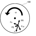
- FIG. 7 is a schematic diagram showing the force acting on the sample solution when the analysis rotating body 100 rotates.
- the sample solution contains a centrifugal force F ⁇ , an Euler force FE, and a Coriolis force Fc.
- the resistance force FR acts.
- the centrifugal force F ⁇ , the Euler force FE, and the Coriolis force Fc are expressed as follows, respectively.
- F ⁇ ⁇ ( ⁇ ⁇ r) (1)
- FE ⁇ (d ⁇ / dt) ⁇ ⁇ (2)
- Fc -2 ⁇ ⁇ v (3)
- ⁇ is the density
- ⁇ is the angular velocity
- r is the radius of gyration
- v is the moving velocity of the sample solution.
- the resistance force FR is considered to be a resistance force mainly due to the fact that the capillary phenomenon of paper acts as a braking force against movement.
- the sample solution reaches a longer distance with the concentration of the measurement target component in the sample solution being higher, starting from the reservoir 100B. That is, the function of the distance detection type ⁇ PADs can be realized while making the movement of the sample solution more rapid. Therefore, according to the analyzer 1, it is possible to shorten the time required to analyze the distance detection type ⁇ PADs.
- FIG. 8 is a schematic diagram showing the results of the analysis performed by the analyzer 1 under various conditions.
- the coarseness of the paper W1: Whatman Filter Paper Grade 1
- the coarse paper W4: Whatman Filter Paper Grade 4
- the analysis was performed by changing the rotation speed of the rotating body for analysis 100 in the case where the installation position of the supply port was close to the center (55 [mm]) and the position far from the center was 60 [mm]. The results are shown.
- 3 to 4 [ ⁇ L] of the food dye aqueous solution was dropped into the supply port as a sample solution.
- the rotator 100 for analysis was rotated at different speeds for 45 seconds.
- the flow velocity of the sample solution increases as the roughness of the paper forming the wax print member 110 increases. Further, according to FIG. 8, it can be seen that the flow velocity of the sample solution becomes slower as the dropping position of the sample solution is closer to the center. Further, according to FIG. 8, it can be seen that the slower the rotation speed of the analysis rotator 100, the slower the flow rate of the sample solution.
- FIG. 9 is a schematic diagram showing the results when an analysis was performed with different microchannel sealing properties.
- FIG. 9 shows the results of analysis performed when the through hole 131 of the top cover member 130 is opened and when the through hole 131 is closed (the upper surface is sealed).
- the rotator 100 for analysis was rotated at different speeds for 45 seconds.
- the flow velocity of the sample solution increases as the rotation speed increases, both when the microchannel is closed (Fully-closed) and when it is opened (Open). Recognize. That is, according to FIG. 9, it is understood that substantially the same analysis can be performed when the microchannel is closed and when it is opened. It should be noted that when the microchannel is closed, the drying of the sample solution is hindered, and therefore it is suitable for analyzing a sample having a slow reaction rate, and when the microchannel is opened, the sample solution cannot be dried. Since it is promoted, it is considered to be suitable for analyzing a sample having a fast reaction rate.
- FIG. 10A and FIG. 10B are schematic diagrams showing the results when analysis is performed by changing the viscosity of the sample solution.
- FIG. 10A shows the relationship between the concentration of ethylene glycol solution and the flow rate
- FIG. 10B shows the result of ethylene glycol solution.
- the relationship between the kinematic viscosity and the flow velocity is shown.
- 10A and 10B show the results of analysis using ethylene glycol solutions of various concentrations as the sample solution.
- 3 [ ⁇ L] of ethylene glycol solution of various concentrations colored with a food dye was dropped as a sample solution into the supply port.
- the rotating body for analysis 100 was rotated at 279 [rad / s] for 45 seconds.
- ⁇ 1 is the dynamic viscosity of the measurement target liquid
- ⁇ 0 is the dynamic viscosity of the control liquid (water)
- t 1 is the moving time required for the reference movement distance of the measurement target liquid
- t 0 is the control liquid (water)
- u1 is the moving speed of the liquid to be measured
- u0 is the moving speed of the control liquid (water).
- FIG. 11 is a schematic diagram showing the result when the analysis is performed by changing the fiber direction of the paper in the microchannel.
- the fiber direction of the paper in the microchannel is changed between the winding direction (MD (Machine Direction) direction) of the roller in the manufacturing process and the direction (CD (Cross Direction) direction) intersecting with the winding direction.
- MD Machine Direction
- CD Cross Direction
- the result of the analysis is shown.
- the fiber direction of commercially available paper includes a winding direction (MD direction) of a roller in a manufacturing process and a direction intersecting with the winding direction (CD direction). Due to these differences, the liquid permeation rate due to a capillary phenomenon changes. It will be done. On the other hand, according to FIG. 11, it can be seen that there is no significant difference in the flow rate of the sample solution regardless of whether the fiber direction of the paper in the microchannel is the MD direction or the CD direction. That is, when the analysis method of the present invention is used, it is considered that the difference in the moving speed of the sample solution between the MD direction and the CD direction is relatively compressed by the centrifugal force, and the influence on the analysis result is suppressed.
- FIG. 12 is a schematic diagram showing the result when the analysis is performed by changing the rotation speed of the analysis rotating body 100.
- the analysis shown in FIG. 12 first, as a sample solution, 3 [ ⁇ L] of the food dye aqueous solution was dropped into the supply port. Next, the rotator 100 for analysis was rotated at different speeds for 45 seconds. According to FIG. 12, it can be seen that the faster the rotation speed, the longer the reaching distance of the sample solution. That is, according to FIG. 12, it is understood that the rotation speed of the analysis rotator 100 should be taken into consideration when performing analysis based on the reach distance of the sample solution.
- FIG. 13 is a schematic diagram showing the relationship between the rotational speed (angular velocity) of the analytical rotator 100 and the outflow state of the sample solution from the valve portion 134.
- FIG. 13 shows the result of observing whether or not the sample solution flows out by changing the rotational speed (angular velocity) of the analysis rotary body 100 with 16 valve parts 134 as targets (samples).
- the rotation speed of the analytical rotator 100 is equal to or lower than the predetermined value
- the sample solution does not flow out from all of the valve portions 134, and the sample solution is discharged from some of the valve portions 134 at the rotation speed equal to or higher than the predetermined value. You can see that it will be leaked.
- the sample solution flows out through all the valve parts 134. That is, by installing the valve unit 134, it is possible to control so that the sample solution does not flow out to the microchannel 111 unless the analysis rotating body 100 is rotated.
- FIG. 14 is a schematic diagram which shows the result at the time of analyzing DNA (double-stranded DNA) using the rotating body 100 for an analysis.
- DNA double-stranded DNA
- FIG. 14 first, 5.5 [ ⁇ L] of a DNA sample solution was dropped as a sample solution into the supply port. Next, the rotator 100 for analysis was rotated for 30 seconds at 260 [rad / s] after 60 seconds when the position where the tip of the sample solution reached reached about 14 [mm]. According to FIG. 14, even in the analysis of DNA, the reaching distance of the sample solution changes depending on the concentration of DNA, and it can be understood that analysis can be performed by the analyzer 1.
- the rotating body for analysis 100 is configured such that the bottom surface of the storage section 100B is wax-printed and the valve section 134 is provided. On the other hand, it is possible to make the structure of the analysis rotating body 100 simpler.
- FIG. 15 is a schematic view showing another configuration example of the analysis rotating body 100.
- the analysis rotating body 100 of the present modified example includes a wax print member 110 and a top cover member 130.
- the wax print member 110 is a disk-shaped member in which a microchannel 111 is formed by wax printing on a base material made of white paper (for example, commercially available filter paper such as Whatman Filter Paper (trademark)), and has a through hole in the center. 112 is formed.
- white paper for example, commercially available filter paper such as Whatman Filter Paper (trademark)
- the micro channel 111 extends in a radial direction from a position separated from the center of the wax print member 110 to a position inside the outer circumference of the wax print member 110.
- a circular supply region 113 for dropping the sample solution is formed at the end of the microchannel 111 on the center side.
- the supply region 113 is a portion of the wax print member 110 where the paper is exposed, and is directly connected to the microchannel 111. Therefore, the function of the valve portion 134, which is different from the analyzing rotary body 100 of FIG. 1, is not mounted on the analyzing rotary body 100 of the present modification.
- a color change indicator is arranged so that the higher the concentration of the measurement target component, the longer the reaching distance.
- a scale for measuring the reaching distance of the sample solution is formed along the micro channel 111 of the wax print member 110.
- the top cover member 130 is an annular member formed by stamping a film, and has the same outer diameter as the wax print member 110. Further, the inner diameter of the top cover member 130 is set to a length that coincides with the end portion on the center side of each microchannel 111 when the top cover member 130 and the wax print member 110 are overlapped with the center aligned. Therefore, the supply area 113 of the wax print member 110 is not covered with the top cover member 130.
- the microchannels 111 of the analytical rotating body 100 of the present modified example are covered with the top cover member 130. Further, the top cover member 130 has a through hole 133 formed at the center. Note that, also in the top cover member 130 in the present modification example, the through hole 131 having the same shape as the microchannel 111 may be formed as in the above-described embodiment.
- the rotator for analysis 100 shown in FIG. 15 can be manufactured by manufacturing the wax print member 110 and the top cover member 130, then stacking them with their centers aligned and laminating with a laminator.
- the rotating body for analysis 100 configured as described above has a structure in which the supply region 113 of the wax print member 110 is used as a supply port for the sample solution, and a flow path for the sample solution that is directly connected to the microchannel 111 from the supply region 113 is formed. Have. Further, in the analysis rotator 100, a plurality of microchannels 111 are arranged radially from the rotation center of the analysis rotator 100.
- FIG. 16 is a schematic diagram showing a cross-sectional structure of the microchannel 111 of the analytical rotator 100 of the present modification. Note that FIG. 16 shows a BB ′ cross section in FIG. 15. As shown in FIG. 16, in the analytical rotator 100 of the present modification, the supply region 113 of the wax print member 110 and the microchannel 111 are flush with each other, and the sample solution dropped in the supply region 113 is It can penetrate into the microchannels 111. The top surface of the microchannel 111 is covered with the top cover member 130. With such a structure, the rotating body for analysis 100 that can be used in the analyzing method of the present invention can be manufactured with a simple manufacturing process and structure.
- the rotating body for analysis 100 of this modification can be used.
- the analysis rotator 100 of the present modification can be used in the analysis device 1 in the above-described embodiment, similarly to the analysis rotator 100 shown in FIG. 1.
- FIG. 17 is a flowchart showing an example of a procedure for analyzing a sample solution using the rotator for analysis 100.
- the sample solution is analyzed using the rotator for analysis 100
- the sample of 7 [ ⁇ L] is supplied to the supply region 113.
- the solution is dropped (step S11).
- it waits for the penetration of the sample solution for 60 seconds (step S12).
- the actuator 21 is rotated for 30 seconds at 279 [rad / s] (step S13).
- control unit 10 is programmed to receive the dropping of the sample solution corresponding to the analysis procedure of FIG. 17, wait for permeation, or control the rotation of the actuator 21, and the above procedure automatically proceeds by executing the program. Can be configured.
- FIG. 18 is a schematic diagram showing another configuration example of the analysis rotating body 100.
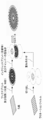
- 19 is an assembly exploded view of the analysis rotating body of FIG. 18, and
- FIG. 20 is a schematic diagram showing a configuration example of a main part of the analysis rotating body 100.
- the analysis rotating body 100 of the present modified example includes a wax print member 110, an inlet member 120, and a top cover member 130.
- the wax print member 110 is a disc-shaped member in which a microchannel 111 is formed by wax printing on a base material made of white paper (for example, commercially available filter paper such as Whatman Filter Paper (trademark)), and has a through hole at the center. 112 is formed. Further, in the wax print member 110 of the present modification, the outer peripheral side end of the microchannel 111 is bent in the circumferential direction and is connected to the absorption pad region 111a (sample solution receiving part).
- the absorption pad region 111a is a region for absorbing and receiving the sample solution that has reached the outer peripheral side end of the microchannel 111.
- the portions other than the portions that become the microchannels 111 and the absorption pad regions 111a are covered with wax that is a hydrophobic material, and the wax has penetrated to the back surface by heat treatment.
- the micro channel 111 extends in a radial direction from a position separated from the center of the wax print member 110 to a position inside the outer circumference of the wax print member 110.
- a chamber 114 (reservoir) having a shape such as a circle or a square for storing the sample solution is formed at the end of the microchannel 111 on the center side.
- the chamber 114 is a portion in which the wax-printed portion of the wax-printed member 110 is die-cut to form a through hole, and by disposing the cover film B at the bottom, it is possible to store the sample solution. Becomes Further, in the micro channel 111, a color change indicator is arranged so that the higher the concentration of the measurement target component, the longer the reaching distance. In addition, a scale for measuring the reaching distance of the sample solution is formed along the micro channel 111 of the wax print member 110.
- the inlet member 120 is a disc-shaped member produced by die-cutting a film, and has a smaller diameter than the wax print member 110.
- a through hole 122 is formed at the center of the inlet member 120, and a plurality of inlet holes 123 for supplying the sample solution to the chamber 114 are formed around the through hole 122.
- the inlet holes 123 are respectively formed at positions overlapping the center-side ends of the chambers 114 when the center is overlapped with the wax print member 110.
- the top cover member 130 is a disc-shaped member manufactured by die-cutting a film, and has the same outer diameter as the wax print member 110. Further, in the top cover member 130, through holes 135 having the same shape as the chamber 114 are formed at positions overlapping with the chambers 114 when the wax print member 110 is overlapped with the center thereof aligned. The through hole 135 constitutes a part of the side wall of the chamber 114 by being overlapped with the chamber 114. A through hole 133 is formed at the center of the top cover member 130.
- FIG. 21 is a schematic diagram showing the structure of the chamber 114.
- the chamber 114 is formed as a space surrounded by the cover film B at the bottom, the wax print member 110, the top cover member 130, and the inlet member 120, and the sample solution is supplied from the inlet hole 123 of the inlet member 120. It has a structure to be supplied.
- the chamber 114 can be formed in various planar shapes according to the amount of the sample solution to be stored and the like.
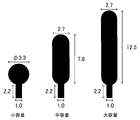
- FIG. 22 is a schematic diagram showing an example of the planar shape of the chamber 114. As shown in FIG.
- the chamber 114 when the chamber 114 is formed, it can have a planar shape such as a circular shape or a rectangular shape when viewed from the top, and the capacity of the chamber 114 also depends on the type of the sample solution and the required storage amount. It can be appropriately selected. In FIG. 22, three types of chambers 114 of small volume, medium volume and large volume are shown. The numerical values in FIG. 22 represent the size of the chamber 114 (unit is millimeter).
- FIG. 23 is a schematic diagram showing a method of manufacturing the analytical rotator 100 in the present modification.
- the pattern of the wax print member 110 is printed on a filter paper of A4 size or the like by a wax printer.
- the wax print member 110 is heated at 150 ° C. for 90 seconds using a hot plate or the like.
- the wax print member 110 is completed by cutting off the portion of the wax print member 110 on which the pattern is formed.
- the inlet member 120 and the top cover member 130 are manufactured by cutting a film having a thickness of about 150 [ ⁇ m] with a cutting machine.
- the wax print member 110 is placed on the film which will be the cover film B at the bottom, and the top cover member 130 and the inlet member 120 are superposed with their centers aligned in this order, and laminated by a laminator.
- the chamber 114 of the wax print member 110, the through hole 135 of the top cover member 130, and the inlet hole 123 of the inlet member 120 are aligned and laminated.
- through holes are formed at positions corresponding to the through holes 112 of the wax print member 110, the through holes 133 of the top cover member 130, and the through holes 122 of the inlet member 120.
- the bottom of the chamber 114 of the wax print member 110 is closed by the cover film B, the through hole 135 of the top cover member 130 is overlapped with the chamber 114, and the inlet member is provided at the center side end of the chamber 114.
- the inlet rotor 123 of 120 is arranged to form the analytical rotator 100 in which the sample solution supply port is formed.
- the through hole 135 of the top cover member 130 is formed inside the end of the wax print member 110 on the center side of the microchannel 111, and a partition wall made of a film is provided between the chamber 114 and the microchannel 111. (Side wall on the outer peripheral side of the through hole 135) exists.
- the lower part of the partition wall is in contact with the surface of the wax-printed portion of the wax-printed member 110 (the portion adjacent to the end of the microchannel 111 on the center side).
- the side wall of the top cover member 130 on the outer peripheral side of the through hole 135 and the surface of the wax-printed portion of the wax printing member 110 (partition contact surface) that is in contact therewith are connected to the microchannel 111 from the supply port of the sample solution.
- the valve portion 134 functions as a valve of the flow path.
- the rotator for analysis 100 uses the inlet hole 123 of the inlet member 120 as a supply port for the sample solution, can store the sample solution in the chamber 114, and can be stored in the microchannel 111 via the valve section 134. It has a structure in which a flow path of a connected sample solution is formed. Further, in the analysis rotator 100, a plurality of microchannels 111 are arranged radially from the rotation center of the analysis rotator 100.
- the sample solution is prevented from flowing out until a certain pressure, and when the certain pressure is exceeded, It has a function of allowing the sample solution to flow out to the microchannel 111.
- the sample solution may permeate the microchannel 111 at an unexpected timing. Can be suppressed.
- the outer peripheral side end of the microchannel 111 is bent in the circumferential direction and is connected to the absorption pad region 111a.
- the analysis of the sample solution can be performed using the analyzer 1 shown in FIG.
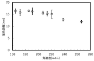
- FIG. 24 is a schematic diagram showing the relationship between the rotation speed of the rotator for analysis 100 and the coloring distance of the microchannel 111. Note that FIG. 24 shows the evaluation results using the nickel standard solution and the nickel coloration indicator DMG (dimethylglyoxime) (the same applies in the following verification).
- a predetermined speed here, 220 [rad / s]
- the rotation speed exceeds the predetermined speed
- the coloration distance is increased. You can see that is shortened. This means that if the rotation speed of the analysis rotator 100 becomes excessively high, leakage of the sample solution will occur, and an appropriate analysis result cannot be obtained.
- FIG. 25 is a schematic diagram showing the relationship between the shape of the chamber 114 and the coloration distance of the microchannel 111. According to FIG. 25, even if the rotator 100 for analysis is rotated for a certain period of time or more, no extension of the coloration distance is observed, so that the time independence of the coloration reaction can be confirmed. As a result, the user does not need to measure the time of color reaction, and a POCT (Point of Care Testing) device with high user convenience can be realized.
- POCT Point of Care Testing
- FIG. 26 is a schematic diagram showing the relationship between the weighing amount of the chamber 114 (or the supply amount of the sample solution) and the coloring distance of the microchannel 111.
- the cases shown by numbers indicate the case where the sample solution of the amount fixed by the micropipette is supplied.
- the reproducibility of the analysis result similar to that of the micropipette was obtained even when the chamber 114 of various weighings of the analysis rotating body 100 was used, and the weighing ability of the chamber 114 was confirmed.
- expert knowledge is required when using, and it is possible to control the supply volume of the sample solution without the need for expensive micropipettes, and to provide an analytical rotary body with performance for actual use cases. 100 can be realized.
- FIG. 27 is a schematic diagram showing the results of nickel ion quantitative measurement using the rotating body for analysis 100. Note that FIG. 27 shows the relationship between the nickel ion concentration and the coloration distance of the microchannel 111 for each of the three types of chamber 114 shapes shown in FIG. Further, FIG. 28 is a schematic diagram showing a coloration state of the micro channel 111 in the case of the measurement result shown in FIG. According to FIG. 28, when the measurement of FIG. 27 is performed, a color boundary line (the position of the pin icon) appears at a position corresponding to the nickel concentration, and it can be seen that nickel was successfully measured.
- a color boundary line the position of the pin icon
- the analysis device 1 includes the analysis rotating body 100, the actuator 21, and the control unit 10.
- the microchannels 111 made of a hydrophilic material are formed along the radial direction.
- the actuator 21 rotates the rotating body 100 for analysis.
- the control unit 10 controls the rotation of the actuator 21.
- the microchannel 111 has an indicator that indicates the concentration of the measurement target component according to the reaching distance of the sample solution.
- the flow rate of the sample solution can be increased while maintaining contact between the hydrophilic material (paper or the like) having the indicator and the sample solution, and the analysis can be performed more quickly. Therefore, the time required to analyze the distance detection type ⁇ PADs can be shortened.
- the analysis rotating body 100 includes a wax print member 110 and a top cover member 130.
- Wax print member 110 includes microchannels 111, and a hydrophobic material is arranged in a portion other than microchannels 111.
- the top cover member 130 constitutes a cover member that covers the microchannel member.
- a hydrophobic material can be disposed on the wax print member 110 made of a hydrophilic material to form the microchannel 111, and the wax print member 110 and the top cover member 130 are integrated for analysis.
- the rotating body 100 can be configured. Therefore, the micro-channel 111 can be designed easily and flexibly, and the rotating body for analysis can be easily manufactured.
- a portion where the hydrophilic material is exposed at the end portion on the center side of the microchannel 111 serves as a sample solution supply region 113.
- the microchannel 111 can be realized with a simple configuration.
- the control unit 10 waits for the sample solution to permeate the hydrophilic material for a set time, and then rotates the actuator 21 to move the hydrophilic material to the hydrophilic material.
- the sample solution is analyzed by moving the permeated sample solution in the microchannel 111. With this, it is possible to realize the analyzer 1 suitable for the case where the analysis is performed promptly after supplying the sample solution to the supply region 113.
- the analysis rotating body 100 includes a storage section 100B and a valve section 134.
- the reservoir 100B is configured such that the end of the microchannel 111 on the center side is surrounded by the hydrophobic material.
- the valve unit 134 is installed between the storage unit 100B and the microchannel 111 to adjust the outflow of the sample solution.
- the analysis rotator 100 includes an inlet cover member 140.
- the inlet cover member 140 suppresses the outflow of the sample solution overflowing from the storage section 100B. Accordingly, even when the sample solution is stored in the storage section 100B, it is possible to prevent the sample solution from overflowing and flowing out.
- the control unit 10 rotates the actuator after the sample solution is supplied to the storage section to cause the sample solution to flow out from the valve section 134 and permeate the sample solution into the end of the microchannel 111 on the center side.
- the sample solution is analyzed by moving the permeated sample solution in the microchannel 111, whereby after the sample solution is supplied to the supply region 113, the sample solution is waited without permeating the sample solution into the hydrophilic material and then analyzed. It is possible to realize the analyzer 1 suitable for performing the above.
- the analysis rotator 100 includes an absorption pad region 111a.
- the absorption pad region 111a receives the sample solution that has reached the outer peripheral side end of the microchannel 111.
- the absorption pad region 111a receives the sample solution that has reached the outer peripheral side end of the microchannel 111.
- the sample solution that has reached the outer peripheral side end of the microchannel 111 can be absorbed, it is possible to prevent the excess sample solution from staying in the microchannel 111, and to more appropriately store the sample solution. Analysis can be performed.
- the analysis method includes a rotation step and a reaction step.
- the rotating step the sample solution is supplied to the end of the microchannel 111 on the center side of the analytical rotator 100 in which the microchannels 111 made of a hydrophilic material are formed in the radial direction. 100 is rotated.
- the indicator solution in which the concentration of the component to be measured is indicated according to the reaching distance of the sample solution in the microchannel 111, reacts with the sample solution.
- the flow rate of the sample solution can be increased while maintaining contact between the hydrophilic material (paper or the like) having the indicator and the sample solution, and the analysis can be performed more quickly. Therefore, the time required to analyze the distance detection type ⁇ PADs can be shortened.
- the microchannels 111 made of a hydrophilic material are formed along the radial direction, and the indicator showing the concentration of the measurement target component according to the reach distance of the sample solution.
- the sample solution moves in the microchannel 111 by being rotated, and the sample solution and the indicator react with each other.
- the flow rate of the sample solution can be increased while maintaining contact between the hydrophilic material (paper or the like) having the indicator and the sample solution, and the analysis can be performed more quickly. Therefore, it is possible to realize the analysis rotating body capable of shortening the time required for the analysis of the distance detection type ⁇ PADs.
- the analysis rotator 100 may have a detailed structure different from that of the analysis rotator 100 described above as long as microchannels extending in the radial direction from the center of rotation are formed.
- the valve part 134 is formed between the storage part 100B and the microchannel 111, but a structure without a valve may be used. That is, the structure of the rotating body for analysis 100 can be variously changed according to the characteristics of the sample to be analyzed, the analysis method, and the like.
- the rotating body for analysis 100 is described as having a disk-shaped configuration, but the present invention is not limited to this. That is, the analysis rotating body 100 may have a shape other than the disk shape as long as it has a symmetrical shape with respect to the center of rotation.
- the present invention can be implemented by appropriately combining the examples described in the above embodiments.
- the absorbent pad 111a shown in the modified example 2 may be provided in the analysis rotating body 100 shown in FIG. 1 or 15.
- the processing for control in the above-described embodiment can be executed by either hardware or software. That is, it is sufficient that the analysis apparatus 1 has a function capable of executing the above-described processing, and the functional configuration and hardware configuration for realizing this function are not limited to the above-described example.
- 1 analysis device 10 control unit, 20 rotation unit, 21 actuator, 100 analysis rotating body, 110 wax print member, 111 microchannel, 111a absorption pad area, 112, 122, 131, 132, 133, 135 through hole, 113 Supply area, 114 chamber, 120 inlet member, 121, 151 protruding part, 123 inlet hole, 130 top cover member, 134 valve part, 140 inlet cover member, 141 notch, 150 laminate mask member, 100A laminated body, 100B storage part , B cover film
Landscapes
- Chemical & Material Sciences (AREA)
- Physics & Mathematics (AREA)
- General Health & Medical Sciences (AREA)
- Life Sciences & Earth Sciences (AREA)
- Analytical Chemistry (AREA)
- Biochemistry (AREA)
- Health & Medical Sciences (AREA)
- General Physics & Mathematics (AREA)
- Immunology (AREA)
- Pathology (AREA)
- Engineering & Computer Science (AREA)
- Chemical Kinetics & Catalysis (AREA)
- Plasma & Fusion (AREA)
- Automatic Analysis And Handling Materials Therefor (AREA)
- Investigating Or Analysing Materials By The Use Of Chemical Reactions (AREA)
Abstract
【課題】距離検出型μPADsの分析に要する時間を短縮すること。 【解決手段】分析装置1は、分析用回転体100と、アクチュエータ21と、制御ユニット10と、を備える。分析用回転体100は、親水性材料で構成されたマイクロチャネル111が半径方向に沿って形成されている。アクチュエータ21は、分析用回転体100を回転させる。制御ユニット10は、アクチュエータ21の回転を制御する。マイクロチャネル111は、検体溶液の到達距離に応じて測定対象成分の濃度が示される指示薬を有する。
Description
本発明は、検体の分析を行う分析装置、分析方法及び分析用回転体に関する。
近年、医療分野において、専門病院への来院、高価な装置あるいは特別な知識を要することなく、先進的な医療を家庭やオンサイトで実施できる手軽な診断手段が求められている。
このような診断手段を実現する場合、安価な診断方法の確立も同時に要求される。
ここで、安価な診断方法を実現するための技術として、μPADs(microfludic Paper-based Analytical Devices)と呼ばれる技術が知られている。
μPADsは、紙による液体の輸送能力を用いて検体の分析を行う技術である。具体的には、μPADsにおいては、親水性であるセルロースが原料であるろ紙を基板材料として、ワックス等の疎水性材料を所望の形状にパターニングする。ろ紙由来の親水性部位がマイクロチャネルとして機能するため、検体溶液量及び測定対象成分の数に応じたデバイスデザインを設計することで、目的に応じた分析デバイスを安価かつ簡便に作製できる。
μPADsには、検体溶液と指示薬を反応させ、カメラやスキャナ等の測定装置で指示薬の呈色強度や変化具合を測定するものや、測定対象成分の濃度が高いほど長い距離を呈するように呈色指示薬を配置しておくことで、呈色距離を読み取るもの(距離検出型μPADs)が存在している。
ここで、カメラやスキャナ等の測定装置で指示薬の呈色強度や変化具合を測定する場合には、測定装置間の個体差や撮影場所の環境光により測定データ間に変動(再現性の低下)が生じることが問題となる。
これに対し、距離検出型μPADsは、特別な読取装置を必要とせず、指示薬呈色距離の到達点を目視にて読み取ることで所望の測定対象成分を測定できる。直感的な測定対象成分濃度の分析が可能であること、測定者毎の読み取り誤差が起こり難いことが大きなメリットであり、実用的かつユーザーフレンドリーなデバイスコンセプトを持つ点で、距離検出型μPADsは、より有用性が高いものと考えられる。
なお、μPADsに関する技術は、例えば、非特許文献1に記載されている。
A.W. Martinez et al., "Patterned paper as a platform for inexpensive, low-volume, portable bioassays", Angew. Chem. Int. Ed. 2007, 46, 1318-1320.
μPADsは、マイクロ流体デバイスであるという特性上、検体溶液が所定の流路内を移動する必要がある。外部装置を必要とすることなく液体を輸送できる点は優れているものの、紙による液体輸送速度は遅く、測定全体に要する分析時間に検体溶液の流速が非常に大きな影響を与える。また、流路の分析ゾーンへの到達後にも、デバイスによっては得られる呈色強度の安定化のため乾燥させる工程が必要となる。その結果、トータルの測定時間として、典型的な例では単純な測定デバイスでも20~30分を要するものとなり、迅速な分析を行う上で足枷となっている。
一方、μPADsにおいて、検体溶液の流速を向上させるための試みも行われており、例えば、紙が有する毛細管の特性よりも孔径の大きい疑似的な毛細管を作製し、その毛細管の中を検体溶液が通る構造とすることで、紙を浸透する液量を減少させて輸送速度を向上させるもの等が実現されている。
しかしながら、距離検出型μPADsの場合、指示薬が配置された紙と検体溶液とが接触することが前提となっており、上述のように、疑似的な毛細管の中を検体溶液が通る構造では、適切な分析を行うことができない。
このように、従来の技術においては、距離検出型μPADsの分析に要する時間を短縮することは困難であった。
一方、μPADsにおいて、検体溶液の流速を向上させるための試みも行われており、例えば、紙が有する毛細管の特性よりも孔径の大きい疑似的な毛細管を作製し、その毛細管の中を検体溶液が通る構造とすることで、紙を浸透する液量を減少させて輸送速度を向上させるもの等が実現されている。
しかしながら、距離検出型μPADsの場合、指示薬が配置された紙と検体溶液とが接触することが前提となっており、上述のように、疑似的な毛細管の中を検体溶液が通る構造では、適切な分析を行うことができない。
このように、従来の技術においては、距離検出型μPADsの分析に要する時間を短縮することは困難であった。
本発明は、距離検出型μPADsの分析に要する時間を短縮することである。
上記目的を達成するため、本発明の一態様の分析装置は、
親水性材料で構成されたマイクロチャネルが半径方向に沿って形成された分析用回転体と、
前記分析用回転体を回転させるアクチュエータと、
前記アクチュエータの回転を制御する制御部と、
を備え、
前記マイクロチャネルは、検体溶液の到達距離に応じて測定対象成分の濃度が示される指示薬を有することを特徴とする。
親水性材料で構成されたマイクロチャネルが半径方向に沿って形成された分析用回転体と、
前記分析用回転体を回転させるアクチュエータと、
前記アクチュエータの回転を制御する制御部と、
を備え、
前記マイクロチャネルは、検体溶液の到達距離に応じて測定対象成分の濃度が示される指示薬を有することを特徴とする。
本発明によれば、距離検出型μPADsの分析に要する時間を短縮することができる。
以下、本発明の実施形態について、図面を用いて説明する。
[本発明の基本的概念]
本発明に係る分析方法では、呈色指示薬を有する紙を検体溶液の流路に配置したマイクロチャネルを、平板(円盤等)からなる分析用回転体の表面に形成する。そして、検体溶液をマイクロチャネルの中心側に供給した後、分析用回転体を回転させることで、遠心力を利用して検体溶液がマイクロチャネルを通る速度を高めている。
このような分析方法とすることで、距離検出型μPADsにおいて、呈色指示薬を有する紙と検体溶液との接触を維持しながら、検体溶液の流速を高めることができ、より迅速に分析を行うことができる。
即ち、本発明に係る分析方法では、距離検出型μPADsの分析に要する時間を短縮することができる。
以下、本発明の一実施形態について具体的に説明する。
[分析用回転体の構成]
図1は、分析用回転体100の構成例を示す模式図である。
また、図2A~図2Eは、図1の分析用回転体100を構成する部材を示す模式図であり、図2Aはワックスプリント部材110の構成を示す模式図、図2Bはインレット部材120の構成を示す模式図、図2Cはトップカバー部材130の構成を示す模式図、図2Dはインレットカバー部材140の構成を示す模式図、図2Eはラミネートマスク部材150の構成を示す模式図である。また、図3は、図1の分析用回転体100の組み立て分解図である。
図1~図3に示すように、分析用回転体100は、ワックスプリント部材110(マイクロチャネル部材)と、インレット部材120と、トップカバー部材130(カバー部材)と、インレットカバー部材140(保護部材)とを備えており、作製時には、ラミネートマスク部材150が用いられる。
ワックスプリント部材110は、白色の紙(例えば、Whatman Filter Paper(商標)等の市販のろ紙)からなる基材にワックスプリントによってマイクロチャネル111が形成された円盤状の部材であり、中心に貫通穴112が形成されている。ワックスプリント部材110においては、マイクロチャネル111となる部分以外が疎水性材料であるワックスで覆われており、ワックスは熱処理によって裏面にまで浸透されている。マイクロチャネル111は、ワックスプリント部材110の中心から離間した位置を起点として、ワックスプリント部材110の外周の内側の位置まで半径方向に延びている。マイクロチャネル111には、測定対象成分の濃度が高いほど長い到達距離を呈するように呈色指示薬が配置されている。なお、ワックスプリント部材110のマイクロチャネル111に沿って、検体溶液の到達距離を測るための目盛りが形成されている。
本実施形態において、ワックスプリント部材110には、全てのマイクロチャネル111に同一種類の呈色指示薬を配置することができる他、異なる種類の呈色指示薬を配置したマイクロチャネル111を混在して形成することが可能である。複数種類の呈色指示薬を配置したマイクロチャネル111を混在して形成した場合、同時に複数種類の分析を行うことができる。
本実施形態において、ワックスプリント部材110には、全てのマイクロチャネル111に同一種類の呈色指示薬を配置することができる他、異なる種類の呈色指示薬を配置したマイクロチャネル111を混在して形成することが可能である。複数種類の呈色指示薬を配置したマイクロチャネル111を混在して形成した場合、同時に複数種類の分析を行うことができる。
インレット部材120は、フィルムを型抜きして作製された円盤状の部材であり、ワックスプリント部材110よりも小径に構成されている。また、インレット部材120の外周には、複数の突出部121が形成されていると共に、中心に貫通穴122が形成されている。この突出部121は、ワックスプリント部材110と中心を合わせて重ねられた場合に、各マイクロチャネル111の中心側の端部(起点)に近接して配置される位置にそれぞれ形成されている。
トップカバー部材130は、フィルムを型抜きして作製された円盤状の部材であり、ワックスプリント部材110と同一の外径に構成されている。また、トップカバー部材130には、ワックスプリント部材110と中心を合わせて重ねられた場合に、各マイクロチャネル111と重なる位置に、マイクロチャネル111と同形状の貫通穴131がそれぞれ形成されている。さらに、各貫通穴131の中心側の端部には、検体溶液の供給口となる貫通穴132がそれぞれ形成されていると共に、中心に貫通穴133が形成されている。
インレットカバー部材140は、フィルムを型抜きして作製された円環状の部材であり、外径がトップカバー部材130の貫通穴132(検体溶液の供給口)の外縁よりも大きく、内径がトップカバー部材130の貫通穴132の中央までの距離となる大きさに構成されている。また、インレットカバー部材140の内周には、トップカバー部材130と中心を合わせて重ねられた場合に、貫通穴132と重なる位置に、小半円形の切り欠き141が形成されている。
ラミネートマスク部材150は、柔軟で一定の厚みがある紙(クッキングペーパー等)を型抜きして作製された円盤状の部材であり、インレット部材120とほぼ同形状に構成されている。ラミネートマスク部材150は、ラミネート時にインレット部材120とインレットカバー部材140とがトップカバー部材130の貫通穴132の位置で接着することを防ぐためのマスク部材である。なお、ラミネートマスク部材150の外周に形成された突出部151は、インレット部材120の突出部121よりもやや小さく形成されている。このような構成とすることで、インレット部材120をラミネートした後、ラミネートマスク部材150を容易に取り出すことができる。
[分析用回転体の作製方法]
次に、上述の分析用回転体100の作製方法について説明する。
初めに、ワックスプリント部材110のパターンをA4サイズのろ紙等にワックスプリンタでプリントする。このようにワックスプリント部材110を作製することで、マイクロチャネル111を容易かつ柔軟に設計することができる。
次に、ワックスプリントされたろ紙を、ホットプレート等を用いて150℃で3分間加熱する。
さらに、ワックスプリント部材110のパターンが形成された部分を切り取ることにより、ワックスプリント部材110が完成する。
次に、上述の分析用回転体100の作製方法について説明する。
初めに、ワックスプリント部材110のパターンをA4サイズのろ紙等にワックスプリンタでプリントする。このようにワックスプリント部材110を作製することで、マイクロチャネル111を容易かつ柔軟に設計することができる。
次に、ワックスプリントされたろ紙を、ホットプレート等を用いて150℃で3分間加熱する。
さらに、ワックスプリント部材110のパターンが形成された部分を切り取ることにより、ワックスプリント部材110が完成する。
インレット部材120については、厚さ100[μm]程度のフィルムをカッティングマシンで型抜きして作製される。
トップカバー部材130及びインレットカバー部材140については、厚さ150[μm]程度のフィルムをカッティングマシンで型抜きして作製される。
ラミネートマスク部材150については、柔軟で一定の厚みがある紙(クッキングペーパー等)をカッティングマシンで型抜きして作製される。
トップカバー部材130及びインレットカバー部材140については、厚さ150[μm]程度のフィルムをカッティングマシンで型抜きして作製される。
ラミネートマスク部材150については、柔軟で一定の厚みがある紙(クッキングペーパー等)をカッティングマシンで型抜きして作製される。
そして、底部のカバーフィルムB(後述)となるフィルムにワックスプリント部材110を載置し、インレット部材120、トップカバー部材130の順で、これらの中心を合わせて重ね合わせ、ラミネータにより第1回目のラミネートを行う。このとき、ワックスプリント部材110のマイクロチャネル111とトップカバー部材130の貫通穴131、及び、インレット部材120の突出部121とトップカバー部材130の貫通穴132の位置を合わせてラミネートされる。なお、カバーフィルムBにおいて、ワックスプリント部材110の貫通穴112、トップカバー部材130の貫通穴133及びインレット部材120の貫通穴122に対応する位置には、貫通穴が形成される。
これにより、ワックスプリント部材110のマイクロチャネル111の部分がトップカバー部材130の貫通穴131で開口すると共に、マイクロチャネル111の中心側の端部にインレット部材120の突出部121が配置され、突出部121の位置にトップカバー部材130の貫通穴132が配置されて検体溶液の供給口が形成された積層体100Aが構成される(図3参照)。なお、トップカバー部材130の貫通穴131,132は独立して形成され、これらの間にはフィルムからなる隔壁が存在する。この隔壁の下部は、ワックスプリント部材110におけるワックスプリントされた部分(マイクロチャネル111の中心側端部に近接する部分)の表面と接触している。トップカバー部材130の隔壁と、これに接触するワックスプリント部材110のワックスプリントされた部分の表面(以下、「隔壁接触面」と称する。)とは、検体溶液の供給口からマイクロチャネル111に繋がる流路のバルブの機能を果たすものとなる。以下、トップカバー部材130の隔壁と、ワックスプリント部材110の隔壁接触面とからなる部分を適宜「バルブ部134」(後述する図4参照)と称する。
次に、積層体100Aを最下層とし、ラミネートマスク部材150、インレットカバー部材140の順で、これらの中心を合わせて重ね合わせ、ラミネータにより第2回目のラミネートを行う。このとき、ラミネートマスク部材150の突出部151とトップカバー部材130の貫通穴132の位置、及び、インレットカバー部材140の切り欠き141とトップカバー部材130の貫通穴132の位置を合わせてラミネートされる。
第2回目のラミネートの際に、ラミネートマスク部材150の突出部151がトップカバー部材130の貫通穴132内においてインレット部材120の突出部121とインレットカバー部材140との間に挟まれることとなる。そのため、インレットカバー部材140がインレット部材120と接着されることを防ぐことができる。
この後、ラミネートマスク部材150を引き抜き、図1に示す分析用回転体100が完成する。
この後、ラミネートマスク部材150を引き抜き、図1に示す分析用回転体100が完成する。
このように構成された分析用回転体100は、トップカバー部材130の貫通穴132を検体溶液の供給口とし、バルブ部134を介してマイクロチャネル111に繋がる検体溶液の流路が形成された構造を有する。
また、分析用回転体100においては、マイクロチャネル111が分析用回転体100の回転中心から放射状に複数配置された構成とされる。
また、分析用回転体100においては、マイクロチャネル111が分析用回転体100の回転中心から放射状に複数配置された構成とされる。
バルブ部134においては、疎水性材料であるトップカバー部材130とワックスプリントされた部分とが接触していることから、一定の圧力までは検体溶液の流出を阻止し、一定の圧力を超えると、検体溶液がマイクロチャネル111に流出することを許容する機能を果たしている。
これにより、検体溶液を供給口(貫通穴132)から滴下した後、分析の開始(分析用回転体100の回転)までに時間を要する場合であっても、不測のタイミングで検体溶液がマイクロチャネル111に浸透することを抑制できる。
これにより、検体溶液を供給口(貫通穴132)から滴下した後、分析の開始(分析用回転体100の回転)までに時間を要する場合であっても、不測のタイミングで検体溶液がマイクロチャネル111に浸透することを抑制できる。
図4は、分析用回転体100のマイクロチャネル111の断面構造を示す模式図である。
なお、図4は、図1におけるA-A’断面を示している。
図4に示すように、分析用回転体100において、トップカバー部材130の貫通穴132が検体溶液の供給口となり、検体溶液がインレット部材120の突出部121、ワックスプリント部材110、トップカバー部材130及びインレットカバー部材140で囲まれた空間(以下、「貯留部100B」と称する。)に導入される。
なお、図4は、図1におけるA-A’断面を示している。
図4に示すように、分析用回転体100において、トップカバー部材130の貫通穴132が検体溶液の供給口となり、検体溶液がインレット部材120の突出部121、ワックスプリント部材110、トップカバー部材130及びインレットカバー部材140で囲まれた空間(以下、「貯留部100B」と称する。)に導入される。
貯留部100Bを囲む部材は疎水性の材料であると共に、バルブ部134においては、疎水性材料であるトップカバー部材130とワックスプリントされた部分とが接触する構造となっている。そのため、バルブ部134において、一定の圧力までは検体溶液の流出が阻止され、一定の圧力を超えると、検体溶液の流出が許容される。
一方、バルブ部134におけるトップカバー部材130の隔壁により、検体溶液がワックスプリント部材110の表面を流出して、マイクロチャネル111の上面から侵入することを防ぐことができる。
また、バルブ部134の上部に重ねてインレットカバー部材140が設置されていることから、検体溶液が貯留部100Bから溢れ、トップカバー部材130の上面からマイクロチャネル111に流入することが抑制されている。
一方、バルブ部134におけるトップカバー部材130の隔壁により、検体溶液がワックスプリント部材110の表面を流出して、マイクロチャネル111の上面から侵入することを防ぐことができる。
また、バルブ部134の上部に重ねてインレットカバー部材140が設置されていることから、検体溶液が貯留部100Bから溢れ、トップカバー部材130の上面からマイクロチャネル111に流入することが抑制されている。
[分析装置の構成]
次に、本発明に係る分析装置1の構成について説明する。
図5は、本発明に係る分析装置1の構成を示す模式図である。
図5において、分析装置1は、制御ユニット10と、回転ユニット20とを備えている。
次に、本発明に係る分析装置1の構成について説明する。
図5は、本発明に係る分析装置1の構成を示す模式図である。
図5において、分析装置1は、制御ユニット10と、回転ユニット20とを備えている。
制御ユニット10は、マイクロコンピュータあるいはPC(Personal Computer)等の情報処理装置によって構成され、回転ユニット20における回転動作を制御する。具体的には、制御ユニット10は、ユーザによる回転速度の設定を受け付け、回転ユニット20に対する回転速度指示信号(電圧指令値を表すPWM信号等)を出力することにより、回転ユニット20における回転速度を制御する。
回転ユニット20は、電動モータ等のアクチュエータ21を備えている。アクチュエータ21の回転軸には、分析用回転体100が設置される。そして、回転ユニット20は、制御ユニット10から入力される回転速度指示信号に応じた速度でアクチュエータ21を回転させる。
このように構成された分析装置1は、距離検出型のμPADsの機能を有するものとなる。
このように構成された分析装置1は、距離検出型のμPADsの機能を有するものとなる。
[作用]
次に、分析装置1により検体溶液の分析を行う場合の作用を説明する。
図6は、分析用回転体100を用いて検体溶液の分析を行う手順の一例を示すフローチャートである。
図6に示すように、分析用回転体100を用いて検体溶液の分析を行う場合、初めに、回転ユニット20に設置された分析用回転体100において、貯留部100Bに3[μL]の検体溶液を滴下する(ステップS1)。
そして、アクチュエータ21を30秒間、279[rad/s]で回転させる(ステップS2)。
このとき、分析用回転体100の検体溶液には、回転による力が作用し、マイクロチャネル111における先端方向(分析用回転体100の半径方向外方)に移動することが促進される。
この後、分析用回転体100のマイクロチャネル111の状態(検体溶液の到達距離等)を確認することで、検体の分析を行うことができる。
なお、制御ユニット10において、図6の分析手順に対応する検体溶液の滴下の受け付けあるいはアクチュエータ21の回転の制御をプログラムしておき、プログラムの実行により、自動的に上記手順が進行するよう構成することができる。
図7は、分析用回転体100が回転した場合に検体溶液に作用する力を示す模式図である。
図7に示すように、分析用回転体100の貯留部100Bに検体溶液が滴下され、分析用回転体100が回転されると、検体溶液には、遠心力Fω、オイラー力FE、コリオリ力Fc、抵抗力FRが作用する。
遠心力Fω、オイラー力FE、コリオリ力Fcは、それぞれ以下のように表される。
Fω=ρω(ω×r) (1)
FE=-ρ(dω/dt)×ω (2)
Fc=-2ρω×v (3)
図7に示すように、分析用回転体100の貯留部100Bに検体溶液が滴下され、分析用回転体100が回転されると、検体溶液には、遠心力Fω、オイラー力FE、コリオリ力Fc、抵抗力FRが作用する。
遠心力Fω、オイラー力FE、コリオリ力Fcは、それぞれ以下のように表される。
Fω=ρω(ω×r) (1)
FE=-ρ(dω/dt)×ω (2)
Fc=-2ρω×v (3)
ただし、式(1)~(3)において、ρは密度、ωは角速度、rは回転半径、vは検体溶液の移動速度である。
なお、抵抗力FRは、紙の毛細管現象が移動に対する制動力として作用することを主因とした抵抗力であると考えられる。
なお、抵抗力FRは、紙の毛細管現象が移動に対する制動力として作用することを主因とした抵抗力であると考えられる。
これらの力が作用する結果、マイクロチャネル111内において、検体溶液は、貯留部100Bを起点として、検体溶液における測定対象成分の濃度が高いほど長い距離まで到達することとなる。
即ち、検体溶液の移動をより迅速なものとしながら、距離検出型μPADsの機能を実現することができる。
したがって、分析装置1によれば、距離検出型μPADsの分析に要する時間を短縮することが可能となる。
即ち、検体溶液の移動をより迅速なものとしながら、距離検出型μPADsの機能を実現することができる。
したがって、分析装置1によれば、距離検出型μPADsの分析に要する時間を短縮することが可能となる。
[効果]
[基本的な条件の相違による効果の検証]
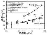
図8は、分析装置1により各種条件を異ならせて分析を行った場合の結果を示す模式図である。
図8においては、ワックスプリント部材110を構成する紙の目の粗さ(目の細かい紙(W1:Whatman Filter Paper Grade 1)と目の粗い紙(W4:Whatman Filter Paper Grade 4))、滴下位置(供給口の設置位置が中心に近いもの(55[mm])と中心から遠いもの60[mm])を異ならせた場合について、分析用回転体100の回転速度を変化させて分析を行った結果を示している。
図8に示す分析では、初めに、検体溶液として、3~4[μL]の食用色素水溶液を供給口に滴下した。
次に、分析用回転体100を異なる速度で45秒間回転させた。
[基本的な条件の相違による効果の検証]
図8は、分析装置1により各種条件を異ならせて分析を行った場合の結果を示す模式図である。
図8においては、ワックスプリント部材110を構成する紙の目の粗さ(目の細かい紙(W1:Whatman Filter Paper Grade 1)と目の粗い紙(W4:Whatman Filter Paper Grade 4))、滴下位置(供給口の設置位置が中心に近いもの(55[mm])と中心から遠いもの60[mm])を異ならせた場合について、分析用回転体100の回転速度を変化させて分析を行った結果を示している。
図8に示す分析では、初めに、検体溶液として、3~4[μL]の食用色素水溶液を供給口に滴下した。
次に、分析用回転体100を異なる速度で45秒間回転させた。
図8によれば、ワックスプリント部材110を構成する紙の目の粗さが粗い程、検体溶液の流速が速くなっていることがわかる。
また、図8によれば、検体溶液の滴下位置が中心に近い程、検体溶液の流速が遅くなっていることがわかる。
さらに、図8によれば、分析用回転体100の回転速度が遅い程、検体溶液の流速が遅くなっていることがわかる。
また、図8によれば、検体溶液の滴下位置が中心に近い程、検体溶液の流速が遅くなっていることがわかる。
さらに、図8によれば、分析用回転体100の回転速度が遅い程、検体溶液の流速が遅くなっていることがわかる。
[マイクロチャネルの密閉性の相違による効果の検証]
図9は、マイクロチャネルの密閉性を異ならせて分析を行った場合の結果を示す模式図である。
図9においては、トップカバー部材130の貫通穴131を開放した場合と密閉(上面を封止)した場合とで分析を行った結果を示している。
図9に示す分析では、初めに、検体溶液として、3[μL]の食用色素水溶液を供給口に滴下した。
次に、分析用回転体100を異なる速度で45秒間回転させた。
図9は、マイクロチャネルの密閉性を異ならせて分析を行った場合の結果を示す模式図である。
図9においては、トップカバー部材130の貫通穴131を開放した場合と密閉(上面を封止)した場合とで分析を行った結果を示している。
図9に示す分析では、初めに、検体溶液として、3[μL]の食用色素水溶液を供給口に滴下した。
次に、分析用回転体100を異なる速度で45秒間回転させた。
図9によれば、一定の回転速度以上では、マイクロチャネルを密閉した場合(Fully-closed)も開放した場合(Open)も、回転速度が速い程、検体溶液の流速が速くなっていることがわかる。
即ち、図9によれば、マイクロチャネルを密閉した場合も開放した場合も、ほぼ同様の分析を行うことができることがわかる。
なお、マイクロチャネルを密閉した場合には、検体溶液の乾燥が阻害されることから、反応速度が遅い検体を分析することに適しており、マイクロチャネルを開放した場合には、検体溶液の乾燥が促進されることから、反応速度が速い検体を分析することに適していると考えられる。
即ち、図9によれば、マイクロチャネルを密閉した場合も開放した場合も、ほぼ同様の分析を行うことができることがわかる。
なお、マイクロチャネルを密閉した場合には、検体溶液の乾燥が阻害されることから、反応速度が遅い検体を分析することに適しており、マイクロチャネルを開放した場合には、検体溶液の乾燥が促進されることから、反応速度が速い検体を分析することに適していると考えられる。
[粘度の高い検体溶液の効果の検証]
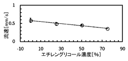
図10A、図10Bは、検体溶液の粘度を異ならせて分析を行った場合の結果を示す模式図であり、図10Aはエチレングリコール溶液の濃度と流速との関係、図10Bはエチレングリコール溶液の動粘性率と流速との関係を示している。
図10A、図10Bにおいては、検体溶液として、各種濃度のエチレングリコール溶液を用いて分析を行った結果を示している。
図10A、図10Bに示す分析では、初めに、検体溶液として、食用色素で着色した各種濃度のエチレングリコール溶液3[μL]を供給口に滴下した。
次に、分析用回転体100を279[rad/s]で45秒間回転させた。
図10A、図10Bは、検体溶液の粘度を異ならせて分析を行った場合の結果を示す模式図であり、図10Aはエチレングリコール溶液の濃度と流速との関係、図10Bはエチレングリコール溶液の動粘性率と流速との関係を示している。
図10A、図10Bにおいては、検体溶液として、各種濃度のエチレングリコール溶液を用いて分析を行った結果を示している。
図10A、図10Bに示す分析では、初めに、検体溶液として、食用色素で着色した各種濃度のエチレングリコール溶液3[μL]を供給口に滴下した。
次に、分析用回転体100を279[rad/s]で45秒間回転させた。
図10Aによれば、エチレングリコール溶液の濃度が高い(即ち、検体溶液の粘度が高い)程、検体溶液の流速が遅くなっていることがわかる。
また、図10Bによれば、エチレングリコール溶液の動粘性率が高い程、検体溶液の流速が遅くなっていることがわかる。
即ち、粘度の高い検体溶液であっても、以下のオストワルド式に従っていることがわかり、検体溶液の流速を目的とする速度に調整する場合等に、粘度の低い検体溶液と同様に取り扱うことができる。
(オストワルド式)
ν1/ν0=t1/t0 ∝ (u1)-1/(u0)-1 (1)
ただし、ν1は測定対象液体の動的粘度、ν0は対照液体(水)の動的粘度、t1は測定対象液体の基準移動距離にかかる移動時間、t0は対照液体(水)の基準移動距離にかかる移動時間、u1は測定対象液体の移動速度、u0は対照液体(水)の移動速度である。
[紙の繊維方向の相違による効果の検証]
図11は、マイクロチャネルにおける紙の繊維方向を異ならせて分析を行った場合の結果を示す模式図である。
図11においては、マイクロチャネルにおける紙の繊維方向を製造工程におけるローラーの巻き取り方向(MD(Machine Direction)方向)と、これに交差する方向(CD(Cross Direction)方向)との間で変化させて分析を行った結果を示している。
図11に示す分析では、初めに、検体溶液として、3[μL]の食用色素水溶液を供給口に滴下した。
次に、分析用回転体100を279[rad/s]で45秒間回転させた。
図11は、マイクロチャネルにおける紙の繊維方向を異ならせて分析を行った場合の結果を示す模式図である。
図11においては、マイクロチャネルにおける紙の繊維方向を製造工程におけるローラーの巻き取り方向(MD(Machine Direction)方向)と、これに交差する方向(CD(Cross Direction)方向)との間で変化させて分析を行った結果を示している。
図11に示す分析では、初めに、検体溶液として、3[μL]の食用色素水溶液を供給口に滴下した。
次に、分析用回転体100を279[rad/s]で45秒間回転させた。
市販の紙の繊維方向には、製造工程におけるローラーの巻き取り方向(MD方向)と、これに交差する方向(CD方向)とがあり、これらの相違により、毛細管現象による液体の浸透速度が変化するものとなる。
これに対し、図11によれば、マイクロチャネルにおける紙の繊維方向をMD方向とした場合もCD方向とした場合も、検体溶液の流速に有意な差がないことがわかる。
即ち、本発明の分析方法を用いた場合、MD方向とCD方向との検体溶液の移動速度の差が遠心力により相対的に圧縮され、分析結果における影響が抑制されていると考えられる。
これに対し、図11によれば、マイクロチャネルにおける紙の繊維方向をMD方向とした場合もCD方向とした場合も、検体溶液の流速に有意な差がないことがわかる。
即ち、本発明の分析方法を用いた場合、MD方向とCD方向との検体溶液の移動速度の差が遠心力により相対的に圧縮され、分析結果における影響が抑制されていると考えられる。
[回転速度の相違による効果の検証]
図12は、分析用回転体100の回転速度を異ならせて分析を行った場合の結果を示す模式図である。
図12に示す分析では、初めに、検体溶液として、3[μL]の食用色素水溶液を供給口に滴下した。
次に、分析用回転体100を異なる速度で45秒間回転させた。
図12によれば、回転速度が速い程、検体溶液の到達距離が長くなっていることがわかる。
即ち、図12によれば、検体溶液の到達距離に基づいて分析を行う場合、分析用回転体100の回転速度を考慮すべきであることがわかる。
図12は、分析用回転体100の回転速度を異ならせて分析を行った場合の結果を示す模式図である。
図12に示す分析では、初めに、検体溶液として、3[μL]の食用色素水溶液を供給口に滴下した。
次に、分析用回転体100を異なる速度で45秒間回転させた。
図12によれば、回転速度が速い程、検体溶液の到達距離が長くなっていることがわかる。
即ち、図12によれば、検体溶液の到達距離に基づいて分析を行う場合、分析用回転体100の回転速度を考慮すべきであることがわかる。
[バルブ部の効果の検証]
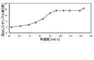
図13は、分析用回転体100の回転速度(角速度)とバルブ部134からの検体溶液の流出状態との関係を示す模式図である。
図13においては、16個のバルブ部134を対象(サンプル)として、分析用回転体100の回転速度(角速度)を異ならせて検体溶液が流出するか否かを観察した結果を示している。
図13によれば、分析用回転体100の回転速度が所定値以下では、全てのバルブ部134から検体溶液は流出せず、所定値以上の回転速度で一部のバルブ部134から検体溶液が流出することがわかる。また、分析用回転体100の回転速度がさらに上昇し、限界値を超えると、全てのバルブ部134で検体溶液が流出することがわかる。
即ち、バルブ部134を設置することにより、分析用回転体100を回転させなければ検体溶液をマイクロチャネル111に流出させないよう制御することができる。
[DNAの分析における効果の検証]
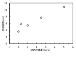
図14は、分析用回転体100を用いてDNA(二本鎖DNA)の分析を行った場合の結果を示す模式図である。
図14に示す分析では、初めに、検体溶液として、5.5[μL]のDNA検体溶液を供給口に滴下した。
次に、検体溶液の先端到達位置がおよそ14[mm]となる60秒が経過した後に、分析用回転体100を260[rad/s]で30秒間回転させた。
図14によれば、DNAの分析においても、DNAの濃度によって検体溶液の到達距離が変化しており、分析装置1によって分析が可能であることがわかる。
図14は、分析用回転体100を用いてDNA(二本鎖DNA)の分析を行った場合の結果を示す模式図である。
図14に示す分析では、初めに、検体溶液として、5.5[μL]のDNA検体溶液を供給口に滴下した。
次に、検体溶液の先端到達位置がおよそ14[mm]となる60秒が経過した後に、分析用回転体100を260[rad/s]で30秒間回転させた。
図14によれば、DNAの分析においても、DNAの濃度によって検体溶液の到達距離が変化しており、分析装置1によって分析が可能であることがわかる。
[変形例1]
上述の実施形態において、分析用回転体100は、貯留部100Bの底面がワックスプリントされていると共に、バルブ部134を備える構成であるものとした。
これに対し、分析用回転体100の構成をより簡易なものとすることが可能である。
図15は、分析用回転体100の他の構成例を示す模式図である。
図15において、本変形例の分析用回転体100は、ワックスプリント部材110と、トップカバー部材130とを備えている。
上述の実施形態において、分析用回転体100は、貯留部100Bの底面がワックスプリントされていると共に、バルブ部134を備える構成であるものとした。
これに対し、分析用回転体100の構成をより簡易なものとすることが可能である。
図15は、分析用回転体100の他の構成例を示す模式図である。
図15において、本変形例の分析用回転体100は、ワックスプリント部材110と、トップカバー部材130とを備えている。
ワックスプリント部材110は、白色の紙(例えば、Whatman Filter Paper(商標)等の市販のろ紙)からなる基材にワックスプリントによってマイクロチャネル111が形成された円盤状の部材であり、中心に貫通穴112が形成されている。ワックスプリント部材110においては、マイクロチャネル111となる部分以外が疎水性材料であるワックスで覆われており、ワックスは熱処理によって裏面にまで浸透されている。マイクロチャネル111は、ワックスプリント部材110の中心から離間した位置を起点として、ワックスプリント部材110の外周の内側の位置まで半径方向に延びている。本変形例のワックスプリント部材110においては、マイクロチャネル111の中心側の端部に検体溶液を滴下するための円形の供給領域113が形成されている。この供給領域113は、ワックスプリント部材110の紙が露出した部分であり、マイクロチャネル111に直接繋がっている。そのため、本変形例の分析用回転体100には、図1の分析用回転体100のようなバルブ部134の機能は実装されていない。また、マイクロチャネル111には、測定対象成分の濃度が高いほど長い到達距離を呈するように呈色指示薬が配置されている。なお、ワックスプリント部材110のマイクロチャネル111に沿って、検体溶液の到達距離を測るための目盛りが形成されている。
トップカバー部材130は、フィルムを型抜きして作製された円環状の部材であり、ワックスプリント部材110と同一の外径に構成されている。また、トップカバー部材130の内径は、ワックスプリント部材110と中心を合わせて重ねられた場合に、各マイクロチャネル111の中心側の端部と一致する長さとされている。そのため、ワックスプリント部材110の供給領域113は、トップカバー部材130で覆われていない。一方、本変形例の分析用回転体100のマイクロチャネル111は、トップカバー部材130で覆われている。さらに、トップカバー部材130は、中心に貫通穴133が形成されている。
なお、本変形例におけるトップカバー部材130においても、上述の実施形態と同様に、マイクロチャネル111と同形状の貫通穴131を形成することとしてもよい。
なお、本変形例におけるトップカバー部材130においても、上述の実施形態と同様に、マイクロチャネル111と同形状の貫通穴131を形成することとしてもよい。
図15に示す分析用回転体100は、ワックスプリント部材110及びトップカバー部材130を作製した後、これらの中心を合わせて重ね合わせ、ラミネータによりラミネートすることで作製することができる。
このように構成された分析用回転体100は、ワックスプリント部材110の供給領域113を検体溶液の供給口とし、供給領域113からマイクロチャネル111に直接繋がる検体溶液の流路が形成された構造を有する。
また、分析用回転体100においては、マイクロチャネル111が分析用回転体100の回転中心から放射状に複数配置された構成とされる。
このように構成された分析用回転体100は、ワックスプリント部材110の供給領域113を検体溶液の供給口とし、供給領域113からマイクロチャネル111に直接繋がる検体溶液の流路が形成された構造を有する。
また、分析用回転体100においては、マイクロチャネル111が分析用回転体100の回転中心から放射状に複数配置された構成とされる。
図16は、本変形例の分析用回転体100のマイクロチャネル111の断面構造を示す模式図である。
なお、図16は、図15におけるB-B’断面を示している。
図16に示すように、本変形例の分析用回転体100において、ワックスプリント部材110の供給領域113とマイクロチャネル111とは面一で繋がっており、供給領域113に滴下された検体溶液は、マイクロチャネル111へと浸透することができる。また、マイクロチャネル111の上面は、トップカバー部材130で覆われている。
このような構成により、簡単な作製工程及び構造で、本発明の分析方法に用いることが可能な分析用回転体100を作製することができる。
なお、図16は、図15におけるB-B’断面を示している。
図16に示すように、本変形例の分析用回転体100において、ワックスプリント部材110の供給領域113とマイクロチャネル111とは面一で繋がっており、供給領域113に滴下された検体溶液は、マイクロチャネル111へと浸透することができる。また、マイクロチャネル111の上面は、トップカバー部材130で覆われている。
このような構成により、簡単な作製工程及び構造で、本発明の分析方法に用いることが可能な分析用回転体100を作製することができる。
本変形例の分析用回転体100は、検体溶液を供給領域113に滴下した後、速やかに分析用回転体100の回転に移行できる場合や、検体溶液を供給領域113に略同時に滴下できる場合等に用いることが好適である。また、検体溶液の粘度が高い場合や、検体溶液と呈色指示薬との反応速度が遅い場合にも、本変形例の分析用回転体100を用いることができる。
なお、本変形例の分析用回転体100は、図1に示す分析用回転体100と同様に、上述の実施形態における分析装置1で使用することができる。
なお、本変形例の分析用回転体100は、図1に示す分析用回転体100と同様に、上述の実施形態における分析装置1で使用することができる。
[作用]
次に、分析装置1により検体溶液の分析を行う場合の作用を説明する。
図17は、分析用回転体100を用いて検体溶液の分析を行う手順の一例を示すフローチャートである。
図17に示すように、分析用回転体100を用いて検体溶液の分析を行う場合、初めに、回転ユニット20に設置された分析用回転体100において、供給領域113に7[μL]の検体溶液を滴下する(ステップS11)。
そして、60秒間、検体溶液の浸透を待機する(ステップS12)。
さらに、アクチュエータ21を30秒間、279[rad/s]で回転させる(ステップS13)。
このとき、分析用回転体100の検体溶液には、回転による力が作用し、マイクロチャネル111における先端方向(分析用回転体100の半径方向外方)に移動することが促進される。
この後、分析用回転体100のマイクロチャネル111の状態(検体溶液の到達距離等)を確認することで、検体の分析を行うことができる。
なお、制御ユニット10において、図17の分析手順に対応する検体溶液の滴下の受け付け、浸透の待機あるいはアクチュエータ21の回転の制御をプログラムしておき、プログラムの実行により、自動的に上記手順が進行するよう構成することができる。
[変形例2]
上述の実施形態及び変形例1に示す分析用回転体100の構成の他、分析用回転体100は以下のような構成とすることが可能である。
図18は、分析用回転体100の他の構成例を示す模式図である。
また、図19は、図18の分析用回転体の組み立て分解図、図20は、分析用回転体100の主要部の構成例を示す模式図である。
図18~図20において、本変形例の分析用回転体100は、ワックスプリント部材110と、インレット部材120と、トップカバー部材130とを備えている。
上述の実施形態及び変形例1に示す分析用回転体100の構成の他、分析用回転体100は以下のような構成とすることが可能である。
図18は、分析用回転体100の他の構成例を示す模式図である。
また、図19は、図18の分析用回転体の組み立て分解図、図20は、分析用回転体100の主要部の構成例を示す模式図である。
図18~図20において、本変形例の分析用回転体100は、ワックスプリント部材110と、インレット部材120と、トップカバー部材130とを備えている。
ワックスプリント部材110は、白色の紙(例えば、Whatman Filter Paper(商標)等の市販のろ紙)からなる基材にワックスプリントによってマイクロチャネル111が形成された円盤状の部材であり、中心に貫通穴112が形成されている。また、本変形例のワックスプリント部材110において、マイクロチャネル111の外周側端部は周方向に屈曲し、吸収パッド領域111a(検体溶液受容部)に繋がっている。吸収パッド領域111aは、マイクロチャネル111の外周側端部に到達した検体溶液を吸収して受容するための領域である。ワックスプリント部材110においては、マイクロチャネル111及び吸収パッド領域111aとなる部分以外が疎水性材料であるワックスで覆われており、ワックスは熱処理によって裏面にまで浸透されている。マイクロチャネル111は、ワックスプリント部材110の中心から離間した位置を起点として、ワックスプリント部材110の外周の内側の位置まで半径方向に延びている。本変形例のワックスプリント部材110においては、マイクロチャネル111の中心側の端部に検体溶液を貯留するための円形または方形等の形状を有するチャンバー114(貯留部)が形成されている。このチャンバー114は、ワックスプリント部材110のワックスプリントされた部分が型抜きされて貫通穴となっている部分であり、底部にカバーフィルムBが配置されることで、検体溶液を貯留することが可能となる。また、マイクロチャネル111には、測定対象成分の濃度が高いほど長い到達距離を呈するように呈色指示薬が配置されている。なお、ワックスプリント部材110のマイクロチャネル111に沿って、検体溶液の到達距離を測るための目盛りが形成されている。
インレット部材120は、フィルムを型抜きして作製された円盤状の部材であり、ワックスプリント部材110よりも小径に構成されている。また、インレット部材120の中心には貫通穴122が形成されていると共に、貫通穴122の周囲には、チャンバー114に検体溶液を供給するための複数のインレットホール123が形成されている。このインレットホール123は、ワックスプリント部材110と中心を合わせて重ねられた場合に、各チャンバー114の中心側の端部に重なる位置にそれぞれ形成されている。
トップカバー部材130は、フィルムを型抜きして作製された円盤状の部材であり、ワックスプリント部材110と同一の外径に構成されている。また、トップカバー部材130には、ワックスプリント部材110と中心を合わせて重ねられた場合に、各チャンバー114と重なる位置に、チャンバー114と同形状の貫通穴135がそれぞれ形成されている。貫通穴135は、チャンバー114と重ね合わせられることにより、チャンバー114の側壁の一部を構成する。なお、トップカバー部材130の中心には貫通穴133が形成されている。
[チャンバーの構成例]
図21は、チャンバー114の構造を示す模式図である。
図21に示すように、チャンバー114は、底部のカバーフィルムB、ワックスプリント部材110、トップカバー部材130及びインレット部材120で囲まれた空間として形成され、インレット部材120のインレットホール123から検体溶液が供給される構造となっている。
また、本変形例における分析用回転体100において、チャンバー114は、貯留する検体溶液の量等に応じて、各種平面形状として形成することができる。
図22は、チャンバー114の平面形状例を示す模式図である。
図22に示すように、チャンバー114を形成する場合、上面視において円形あるいは方形等の平面形状とすることができると共に、チャンバー114の容量も、検体溶液の種類や必要な貯留量等に応じて適宜選択することが可能である。
図22においては、小容量、中容量及び大容量の3種類のチャンバー114が示されている。なお、図22における数値は、チャンバー114のサイズ(単位はミリメートル)を表している。
[分析用回転体の作製方法]
次に、本変形例の分析用回転体100の作製方法について説明する。
図23は、本変形例における分析用回転体100の作製方法を示す模式図である。
図23に示すように、分析用回転体100を作製する場合には、初めに、ワックスプリント部材110のパターンをA4サイズのろ紙等にワックスプリンタでプリントする。このようにワックスプリント部材110を作製することで、マイクロチャネル111を容易かつ柔軟に設計することができる。
次に、ワックスプリントされたろ紙を、ホットプレート等を用いて150℃で90秒間加熱する。
さらに、ワックスプリント部材110のパターンが形成された部分を切り取ることにより、ワックスプリント部材110が完成する。
インレット部材120及びトップカバー部材130については、厚さ150[μm]程度のフィルムをカッティングマシンで型抜きして作製される。
そして、底部のカバーフィルムBとなるフィルムにワックスプリント部材110を載置し、トップカバー部材130、インレット部材120の順で、これらの中心を合わせて重ね合わせ、ラミネータによりラミネートを行う。このとき、ワックスプリント部材110のチャンバー114、トップカバー部材130の貫通穴135、及び、インレット部材120のインレットホール123の位置を合わせてラミネートされる。なお、カバーフィルムBにおいて、ワックスプリント部材110の貫通穴112、トップカバー部材130の貫通穴133及びインレット部材120の貫通穴122に対応する位置には、貫通穴が形成される。
これにより、ワックスプリント部材110のチャンバー114の底部がカバーフィルムBで塞がれ、チャンバー114にトップカバー部材130の貫通穴135が重ねて配置されると共に、チャンバー114の中心側端部にインレット部材120のインレットホール123が配置されて検体溶液の供給口が形成された分析用回転体100が構成される。なお、トップカバー部材130の貫通穴135は、ワックスプリント部材110のマイクロチャネル111の中心側の端部よりも内側に形成されており、チャンバー114とマイクロチャネル111との間にはフィルムからなる隔壁(貫通穴135の外周側の側壁)が存在する。この隔壁の下部は、ワックスプリント部材110におけるワックスプリントされた部分(マイクロチャネル111の中心側端部に近接する部分)の表面と接触している。トップカバー部材130における貫通穴135の外周側の側壁と、これに接触するワックスプリント部材110のワックスプリントされた部分の表面(隔壁接触面)とは、検体溶液の供給口からマイクロチャネル111に繋がる流路のバルブの機能を果たすバルブ部134となる。
このように構成された分析用回転体100は、インレット部材120のインレットホール123を検体溶液の供給口とし、チャンバー114に検体溶液を貯留可能であると共に、バルブ部134を介してマイクロチャネル111に繋がる検体溶液の流路が形成された構造を有する。
また、分析用回転体100においては、マイクロチャネル111が分析用回転体100の回転中心から放射状に複数配置された構成とされる。
また、分析用回転体100においては、マイクロチャネル111が分析用回転体100の回転中心から放射状に複数配置された構成とされる。
バルブ部134においては、疎水性材料であるトップカバー部材130とワックスプリントされた部分とが接触していることから、一定の圧力までは検体溶液の流出を阻止し、一定の圧力を超えると、検体溶液がマイクロチャネル111に流出することを許容する機能を果たしている。
これにより、検体溶液をチャンバー114に貯留した後、分析の開始(分析用回転体100の回転)までに時間を要する場合であっても、不測のタイミングで検体溶液がマイクロチャネル111に浸透することを抑制できる。
これにより、検体溶液をチャンバー114に貯留した後、分析の開始(分析用回転体100の回転)までに時間を要する場合であっても、不測のタイミングで検体溶液がマイクロチャネル111に浸透することを抑制できる。
また、本変形例の分析用回転体100において、マイクロチャネル111の外周側端部は周方向に屈曲し、吸収パッド領域111aに繋がっている。
これにより、マイクロチャネル111の外周側端部に到達した検体溶液を吸収することができるため、余分な検体溶液がマイクロチャネル111に滞留することを抑制することが可能となり、より適切に検体溶液の分析を行うことができる。
なお、本変形例の分析用回転体100においても、図5に示す分析装置1を用いて検体溶液の分析を行うことができる。
これにより、マイクロチャネル111の外周側端部に到達した検体溶液を吸収することができるため、余分な検体溶液がマイクロチャネル111に滞留することを抑制することが可能となり、より適切に検体溶液の分析を行うことができる。
なお、本変形例の分析用回転体100においても、図5に示す分析装置1を用いて検体溶液の分析を行うことができる。
[効果]
[回転速度による効果の検証]
図24は、分析用回転体100の回転速度とマイクロチャネル111の呈色距離との関係を示す模式図である。
なお、図24は、ニッケル標準溶液とニッケル呈色指示薬DMG(ジメチルグリオキシム)を用いた評価結果を示している(以下の検証において同様である)。
図24によれば、分析用回転体100の回転速度が所定速度(ここでは、220[rad/s])までは正常な長さの呈色距離を示すものの、所定速度を超えると呈色距離が短くなっていることがわかる。
これは、分析用回転体100の回転速度が過度に高速になると、検体溶液の漏れが発生するため、適切な分析結果を得ることができないことを表している。
[チャンバーの形状による効果の検証]
図25は、チャンバー114の形状とマイクロチャネル111の呈色距離との関係を示す模式図である。
図25によれば、分析用回転体100を一定時間以上回転させても、呈色距離の延長は見られないことから、呈色反応の時間非依存性を確認することができる。
これにより、ユーザは、呈色反応させた時間を測定することが不要となり、ユーザの利便性が高いPOCT(Point of Care Testing)デバイスを実現することができる。
図25は、チャンバー114の形状とマイクロチャネル111の呈色距離との関係を示す模式図である。
図25によれば、分析用回転体100を一定時間以上回転させても、呈色距離の延長は見られないことから、呈色反応の時間非依存性を確認することができる。
これにより、ユーザは、呈色反応させた時間を測定することが不要となり、ユーザの利便性が高いPOCT(Point of Care Testing)デバイスを実現することができる。
[チャンバーの秤量による効果の検証]
図26は、チャンバー114の秤量(または検体溶液の供給量)とマイクロチャネル111の呈色距離との関係を示す模式図である。
なお、図26中の検体溶液の供給量において、数字で示されているケースは、マイクロピペットにより固定された量の検体溶液を供給した場合を示している。
図26によれば、分析用回転体100の各種秤量のチャンバー114を用いた場合にも、マイクロピペットと同様の分析結果の再現性が得られ、チャンバー114が有する秤量の能力が確認された。
これにより、使用する際に専門知識が必要となると共に、高価であるマイクロピペットを必要とせずに検体溶液の供給量を制御することができ、現実のユースケース仕向の性能を有する分析用回転体100を実現することができる。
[具体的な測定対象における効果の検証]
図27は、分析用回転体100を用いたニッケルイオン定量測定結果を示す模式図である。
なお、図27は、図22に示す3種類のチャンバー114の形状それぞれの場合におけるニッケルイオン濃度とマイクロチャネル111の呈色距離との関係を示している。
また、図28は、図27に示す測定結果の場合のマイクロチャネル111の呈色状態を示す模式図である。
図28によれば、図27の測定を行った場合、ニッケル濃度に応じた位置に呈色の境界線(ピンアイコンの位置)が現れ、ニッケルを測定することに成功したことがわかる。
図27は、分析用回転体100を用いたニッケルイオン定量測定結果を示す模式図である。
なお、図27は、図22に示す3種類のチャンバー114の形状それぞれの場合におけるニッケルイオン濃度とマイクロチャネル111の呈色距離との関係を示している。
また、図28は、図27に示す測定結果の場合のマイクロチャネル111の呈色状態を示す模式図である。
図28によれば、図27の測定を行った場合、ニッケル濃度に応じた位置に呈色の境界線(ピンアイコンの位置)が現れ、ニッケルを測定することに成功したことがわかる。
以上のように、本実施形態に係る分析装置1は、分析用回転体100と、アクチュエータ21と、制御ユニット10と、を備える。
分析用回転体100は、親水性材料で構成されたマイクロチャネル111が半径方向に沿って形成されている。
アクチュエータ21は、分析用回転体100を回転させる。
制御ユニット10は、アクチュエータ21の回転を制御する。
マイクロチャネル111は、検体溶液の到達距離に応じて測定対象成分の濃度が示される指示薬を有する。
これにより、指示薬を有する親水性材料(紙等)と検体溶液との接触を維持しながら、検体溶液の流速を高めることができ、より迅速に分析を行うことができる。
したがって、距離検出型μPADsの分析に要する時間を短縮することができる。
分析用回転体100は、親水性材料で構成されたマイクロチャネル111が半径方向に沿って形成されている。
アクチュエータ21は、分析用回転体100を回転させる。
制御ユニット10は、アクチュエータ21の回転を制御する。
マイクロチャネル111は、検体溶液の到達距離に応じて測定対象成分の濃度が示される指示薬を有する。
これにより、指示薬を有する親水性材料(紙等)と検体溶液との接触を維持しながら、検体溶液の流速を高めることができ、より迅速に分析を行うことができる。
したがって、距離検出型μPADsの分析に要する時間を短縮することができる。
分析用回転体100は、ワックスプリント部材110と、トップカバー部材130と、を備える。
ワックスプリント部材110は、マイクロチャネル111を備え、マイクロチャネル111以外の部分に疎水性材料が配置されている。
トップカバー部材130は、マイクロチャネル部材を覆うカバー部材を構成する。
これにより、親水性材料で構成されたワックスプリント部材110に疎水性材料を配置してマイクロチャネル111を構成することができると共に、このワックスプリント部材110とトップカバー部材130とを一体とした分析用回転体100を構成することができる。
したがって、マイクロチャネル111を容易かつ柔軟に設計できると共に、簡単に分析用回転体を作製することができる。
ワックスプリント部材110は、マイクロチャネル111を備え、マイクロチャネル111以外の部分に疎水性材料が配置されている。
トップカバー部材130は、マイクロチャネル部材を覆うカバー部材を構成する。
これにより、親水性材料で構成されたワックスプリント部材110に疎水性材料を配置してマイクロチャネル111を構成することができると共に、このワックスプリント部材110とトップカバー部材130とを一体とした分析用回転体100を構成することができる。
したがって、マイクロチャネル111を容易かつ柔軟に設計できると共に、簡単に分析用回転体を作製することができる。
分析用回転体100は、マイクロチャネル111の中心側の端部において親水性材料が露出した部分が検体溶液の供給領域113とされている。
これにより、簡単な構成でマイクロチャネル111を実現することができる。
これにより、簡単な構成でマイクロチャネル111を実現することができる。
制御ユニット10は、検体溶液の供給領域113に検体溶液が供給された後、検体溶液の親水性材料への浸透を設定された時間だけ待機し、続いてアクチュエータ21を回転させ、親水性材料へ浸透した検体溶液をマイクロチャネル111において移動させることにより、検体溶液の分析を行う。
これにより、検体溶液を供給領域113に供給した後、速やかに分析を行う場合に好適な分析装置1を実現することができる。
これにより、検体溶液を供給領域113に供給した後、速やかに分析を行う場合に好適な分析装置1を実現することができる。
分析用回転体100は、貯留部100Bと、バルブ部134と、を備える。
貯留部100Bは、マイクロチャネル111の中心側の端部に疎水性材料で囲まれるように構成される。
バルブ部134は、貯留部100Bとマイクロチャネル111との間に検体溶液の流出を調整するために設置される。
これにより、検体溶液を供給領域113に供給した後、親水性材料に検体溶液を浸透させない状態とし、分析時にバルブ部134から検体溶液を流出させることが可能な分析用回転体100を実現することができる。
貯留部100Bは、マイクロチャネル111の中心側の端部に疎水性材料で囲まれるように構成される。
バルブ部134は、貯留部100Bとマイクロチャネル111との間に検体溶液の流出を調整するために設置される。
これにより、検体溶液を供給領域113に供給した後、親水性材料に検体溶液を浸透させない状態とし、分析時にバルブ部134から検体溶液を流出させることが可能な分析用回転体100を実現することができる。
分析用回転体100は、インレットカバー部材140を備える。
インレットカバー部材140は、貯留部100Bから溢れた検体溶液の流出を抑制する。
これにより、貯留部100Bに検体溶液を貯留する場合であっても、検体溶液が溢れて流出する事態を抑制することができる。
インレットカバー部材140は、貯留部100Bから溢れた検体溶液の流出を抑制する。
これにより、貯留部100Bに検体溶液を貯留する場合であっても、検体溶液が溢れて流出する事態を抑制することができる。
制御ユニット10は、貯留部に検体溶液が供給された後、アクチュエータを回転させることにより、バルブ部134から検体溶液を流出させて当該検体溶液をマイクロチャネル111の中心側の端部に浸透させ、浸透した検体溶液をマイクロチャネル111において移動させることにより、検体溶液の分析を行う
これにより、検体溶液を供給領域113に供給した後、親水性材料に検体溶液を浸透させることなく待機してから分析を行う場合に好適な分析装置1を実現することができる。
これにより、検体溶液を供給領域113に供給した後、親水性材料に検体溶液を浸透させることなく待機してから分析を行う場合に好適な分析装置1を実現することができる。
分析用回転体100は、吸収パッド領域111aを備える。
吸収パッド領域111aは、マイクロチャネル111の外周側端部に到達した検体溶液を受容する。
これにより、マイクロチャネル111の外周側端部に到達した検体溶液を吸収することができるため、余分な検体溶液がマイクロチャネル111に滞留することを抑制することが可能となり、より適切に検体溶液の分析を行うことができる。
吸収パッド領域111aは、マイクロチャネル111の外周側端部に到達した検体溶液を受容する。
これにより、マイクロチャネル111の外周側端部に到達した検体溶液を吸収することができるため、余分な検体溶液がマイクロチャネル111に滞留することを抑制することが可能となり、より適切に検体溶液の分析を行うことができる。
また、本実施形態に係る分析方法は、回転ステップと、反応ステップとを含む。
回転ステップでは、親水性材料で構成されたマイクロチャネル111が半径方向に沿って形成された分析用回転体100においてマイクロチャネル111の中心側の端部に検体溶液が供給され、当該分析用回転体100が回転される。
反応ステップでは、マイクロチャネル111において検体溶液の到達距離に応じて測定対象成分の濃度が示される指示薬と検体溶液とが反応する。
これにより、指示薬を有する親水性材料(紙等)と検体溶液との接触を維持しながら、検体溶液の流速を高めることができ、より迅速に分析を行うことができる。
したがって、距離検出型μPADsの分析に要する時間を短縮することができる。
回転ステップでは、親水性材料で構成されたマイクロチャネル111が半径方向に沿って形成された分析用回転体100においてマイクロチャネル111の中心側の端部に検体溶液が供給され、当該分析用回転体100が回転される。
反応ステップでは、マイクロチャネル111において検体溶液の到達距離に応じて測定対象成分の濃度が示される指示薬と検体溶液とが反応する。
これにより、指示薬を有する親水性材料(紙等)と検体溶液との接触を維持しながら、検体溶液の流速を高めることができ、より迅速に分析を行うことができる。
したがって、距離検出型μPADsの分析に要する時間を短縮することができる。
また、本実施形態に係る分析用回転体100は、親水性材料で構成されたマイクロチャネル111が半径方向に沿って形成され、検体溶液の到達距離に応じて測定対象成分の濃度が示される指示薬をマイクロチャネル111に有し、回転されることにより、検体溶液がマイクロチャネル111を移動して、検体溶液と指示薬とが反応する構成を有する。
これにより、指示薬を有する親水性材料(紙等)と検体溶液との接触を維持しながら、検体溶液の流速を高めることができ、より迅速に分析を行うことができる。
したがって、距離検出型μPADsの分析に要する時間を短縮することが可能な分析用回転体を実現することができる。
これにより、指示薬を有する親水性材料(紙等)と検体溶液との接触を維持しながら、検体溶液の流速を高めることができ、より迅速に分析を行うことができる。
したがって、距離検出型μPADsの分析に要する時間を短縮することが可能な分析用回転体を実現することができる。
なお、本発明は、本発明の効果を奏する範囲で変形、改良等を適宜行うことができ、上述の実施形態に限定されない。
例えば、分析用回転体100は、回転中心から半径方向に延びるマイクロチャネルが形成されていれば、細部の構造は上述した分析用回転体100と異なるものとしてもよい。一例として、図1の分析用回転体100では、貯留部100Bとマイクロチャネル111との間にバルブ部134が形成されているものとしたが、バルブを備えない構造としてもよい。即ち、分析用回転体100の構造は、分析対象とする検体の特性や分析方法等の目的に合わせて、種々変更することが可能である。
例えば、分析用回転体100は、回転中心から半径方向に延びるマイクロチャネルが形成されていれば、細部の構造は上述した分析用回転体100と異なるものとしてもよい。一例として、図1の分析用回転体100では、貯留部100Bとマイクロチャネル111との間にバルブ部134が形成されているものとしたが、バルブを備えない構造としてもよい。即ち、分析用回転体100の構造は、分析対象とする検体の特性や分析方法等の目的に合わせて、種々変更することが可能である。
また、上述の実施形態において、分析用回転体100を円盤状の構成を有するものとして説明したが、これに限られない。即ち、分析用回転体100は、回転中心に対して対称な形状であれば、円盤状以外の形状としてもよい。
また、上述の実施形態に記載された例を適宜組み合わせて、本発明を実施することが可能である。例えば、変形例2で示した吸収パッド111aを図1または図15の分析用回転体100に備えることとしてもよい。
上述の実施形態における制御のための処理は、ハードウェア及びソフトウェアのいずれにより実行させることも可能である。
即ち、上述の処理を実行できる機能が分析装置1に備えられていればよく、この機能を実現するためにどのような機能構成及びハードウェア構成とするかは上述の例に限定されない。
上述の実施形態における制御のための処理は、ハードウェア及びソフトウェアのいずれにより実行させることも可能である。
即ち、上述の処理を実行できる機能が分析装置1に備えられていればよく、この機能を実現するためにどのような機能構成及びハードウェア構成とするかは上述の例に限定されない。
なお、上記実施形態は、本発明を適用した一例を示しており、本発明の技術的範囲を限定するものではない。即ち、本発明は、本発明の要旨を逸脱しない範囲で、省略や置換等種々の変更を行うことができ、上記実施形態以外の各種実施形態を取ることが可能である。本発明が取ることができる各種実施形態及びその変形は、特許請求の範囲に記載された発明とその均等の範囲に含まれる。
1 分析装置、10 制御ユニット、20 回転ユニット、21 アクチュエータ、100 分析用回転体、110 ワックスプリント部材、111 マイクロチャネル、111a 吸収パッド領域、112,122,131,132,133,135 貫通穴、113 供給領域、114 チャンバー、120 インレット部材、121,151 突出部、123 インレットホール、130 トップカバー部材、134 バルブ部、140 インレットカバー部材、141 切り欠き、150 ラミネートマスク部材、100A 積層体、100B 貯留部、B カバーフィルム
Claims (10)
- 親水性材料で構成されたマイクロチャネルが半径方向に沿って形成された分析用回転体と、
前記分析用回転体を回転させるアクチュエータと、
前記アクチュエータの回転を制御する制御部と、
を備え、
前記マイクロチャネルは、検体溶液の到達距離に応じて測定対象成分の濃度が示される指示薬を有することを特徴とする分析装置。 - 前記分析用回転体は、
前記マイクロチャネルを備え、前記マイクロチャネル以外の部分に疎水性材料が配置されたマイクロチャネル部材と、
前記マイクロチャネル部材を覆うカバー部材と、
を備えることを特徴とする請求項1に記載の分析装置。 - 前記分析用回転体は、前記マイクロチャネルの中心側の端部において親水性材料が露出した部分が検体溶液の供給領域とされていることを特徴とする請求項1または2に記載の分析装置。
- 前記制御部は、前記検体溶液の供給領域に検体溶液が供給された後、検体溶液の親水性材料への浸透を設定された時間だけ待機し、続いて前記アクチュエータを回転させ、親水性材料へ浸透した検体溶液を前記マイクロチャネルにおいて移動させることにより、検体溶液の分析を行うことを特徴とする請求項3に記載の分析装置。
- 前記分析用回転体は、前記マイクロチャネルの中心側の端部に疎水性材料で囲まれた検体溶液の貯留部と、
前記貯留部と前記マイクロチャネルとの間に前記検体溶液の流出を調整するためのバルブ部と、
を備えることを特徴とする請求項1または2に記載の分析装置。 - 前記分析用回転体は、前記貯留部から溢れた検体溶液の流出を抑制するための保護部材を備えることを特徴とする請求項5に記載の分析装置。
- 前記制御部は、前記貯留部に検体溶液が供給された後、前記アクチュエータを回転させることにより、前記バルブ部から検体溶液を流出させて当該検体溶液を前記マイクロチャネルの中心側の端部に浸透させ、浸透した検体溶液を前記マイクロチャネルにおいて移動させることにより、検体溶液の分析を行うことを特徴とする請求項6に記載の分析装置。
- 前記分析用回転体は、前記マイクロチャネルの外周側端部に到達した検体溶液を受容する検体溶液受容部を備えることを特徴とする請求項1から7のいずれか1項に記載の分析装置。
- 親水性材料で構成されたマイクロチャネルが半径方向に沿って形成された分析用回転体において前記マイクロチャネルの中心側の端部に検体溶液を供給し、当該分析用回転体を回転させる回転ステップと、
前記マイクロチャネルにおいて検体溶液の到達距離に応じて測定対象成分の濃度が示される指示薬と前記検体溶液とを反応させる反応ステップと、
を含むことを特徴とする分析方法。 - 親水性材料で構成されたマイクロチャネルが半径方向に沿って形成され、検体溶液の到達距離に応じて測定対象成分の濃度が示される指示薬を前記マイクロチャネルに有し、回転されることにより、前記検体溶液が前記マイクロチャネルを移動して、前記検体溶液と前記指示薬とが反応することを特徴とする分析用回転体。
Applications Claiming Priority (2)
| Application Number | Priority Date | Filing Date | Title |
|---|---|---|---|
| JP2018-209278 | 2018-11-06 | ||
| JP2018209278A JP2022017614A (ja) | 2018-11-06 | 2018-11-06 | 分析装置、分析方法及び分析用回転体 |
Publications (1)
| Publication Number | Publication Date |
|---|---|
| WO2020095914A1 true WO2020095914A1 (ja) | 2020-05-14 |
Family
ID=70611969
Family Applications (1)
| Application Number | Title | Priority Date | Filing Date |
|---|---|---|---|
| PCT/JP2019/043345 Ceased WO2020095914A1 (ja) | 2018-11-06 | 2019-11-05 | 分析装置、分析方法及び分析用回転体 |
Country Status (2)
| Country | Link |
|---|---|
| JP (1) | JP2022017614A (ja) |
| WO (1) | WO2020095914A1 (ja) |
Citations (9)
| Publication number | Priority date | Publication date | Assignee | Title |
|---|---|---|---|---|
| JPS5175596A (ja) * | 1974-12-18 | 1976-06-30 | Becton Dickinson Co | |
| JP2002202310A (ja) * | 2000-10-27 | 2002-07-19 | Morinaga Milk Ind Co Ltd | 物質の検出試薬及び検出方法 |
| JP2003524145A (ja) * | 1998-05-08 | 2003-08-12 | ユィロス・アクチボラグ | 微流体装置 |
| JP2006138652A (ja) * | 2004-11-10 | 2006-06-01 | Matsushita Electric Ind Co Ltd | 分析装置 |
| JP2008525798A (ja) * | 2004-12-23 | 2008-07-17 | キンバリー クラーク ワールドワイド インコーポレイテッド | マイクロ流体検定デバイス |
| WO2012105721A1 (ja) * | 2011-02-05 | 2012-08-09 | 野地 澄晴 | 3次元紙マイクロ検査診断用チップ |
| US20130302830A1 (en) * | 2010-06-17 | 2013-11-14 | Rajesh K. Mehra | Rotors for immunoassays |
| JP2016045200A (ja) * | 2014-08-25 | 2016-04-04 | ゼロックス コーポレイションXerox Corporation | 用紙ベースのセンサのロバストな比色分析処理方法 |
| WO2018170572A1 (pt) * | 2017-03-23 | 2018-09-27 | Fundação Oswaldo Cruz | Dispositivo de diagnóstico de simetria radial do tipo fluxo lateral, e sistema de leitura de um dispositivo diagnóstico de simetria radial do tipo fluxo lateral |
-
2018
- 2018-11-06 JP JP2018209278A patent/JP2022017614A/ja active Pending
-
2019
- 2019-11-05 WO PCT/JP2019/043345 patent/WO2020095914A1/ja not_active Ceased
Patent Citations (9)
| Publication number | Priority date | Publication date | Assignee | Title |
|---|---|---|---|---|
| JPS5175596A (ja) * | 1974-12-18 | 1976-06-30 | Becton Dickinson Co | |
| JP2003524145A (ja) * | 1998-05-08 | 2003-08-12 | ユィロス・アクチボラグ | 微流体装置 |
| JP2002202310A (ja) * | 2000-10-27 | 2002-07-19 | Morinaga Milk Ind Co Ltd | 物質の検出試薬及び検出方法 |
| JP2006138652A (ja) * | 2004-11-10 | 2006-06-01 | Matsushita Electric Ind Co Ltd | 分析装置 |
| JP2008525798A (ja) * | 2004-12-23 | 2008-07-17 | キンバリー クラーク ワールドワイド インコーポレイテッド | マイクロ流体検定デバイス |
| US20130302830A1 (en) * | 2010-06-17 | 2013-11-14 | Rajesh K. Mehra | Rotors for immunoassays |
| WO2012105721A1 (ja) * | 2011-02-05 | 2012-08-09 | 野地 澄晴 | 3次元紙マイクロ検査診断用チップ |
| JP2016045200A (ja) * | 2014-08-25 | 2016-04-04 | ゼロックス コーポレイションXerox Corporation | 用紙ベースのセンサのロバストな比色分析処理方法 |
| WO2018170572A1 (pt) * | 2017-03-23 | 2018-09-27 | Fundação Oswaldo Cruz | Dispositivo de diagnóstico de simetria radial do tipo fluxo lateral, e sistema de leitura de um dispositivo diagnóstico de simetria radial do tipo fluxo lateral |
Also Published As
| Publication number | Publication date |
|---|---|
| JP2022017614A (ja) | 2022-01-26 |
Similar Documents
| Publication | Publication Date | Title |
|---|---|---|
| Noh et al. | Fluidic timers for time-dependent, point-of-care assays on paper | |
| Martinez et al. | Programmable diagnostic devices made from paper and tape | |
| Badr et al. | Fluorescent ion-selective optode membranes incorporated onto a centrifugal microfluidics platform | |
| US11835536B2 (en) | Device and method for qualitative and quantitative analysis of heavy metals utilizing rotary disc system | |
| US20210220822A1 (en) | Passive pumps for microfluidic devices | |
| US11673138B2 (en) | Measurement of an analyte with a cartridge | |
| EP1644184A2 (en) | Fluidic circuits, methods and apparatus for use of whole blood samples in colorimetric assays | |
| WO2020095914A1 (ja) | 分析装置、分析方法及び分析用回転体 | |
| Vereshchagina et al. | Multi-material paper-disc devices for low cost biomedical diagnostics | |
| JP2019132587A (ja) | 分析用トレー | |
| WO2025172518A1 (en) | Film-based blood filter element | |
| JPH0882590A (ja) | 試料セル保持部材 | |
| Li | Development of a microfluidic fluorescence immunosensor for Point-of-Care diagnostics | |
| KR20200122736A (ko) | 알데히드류 또는 케톤류 검출용 마이크로 디바이스 | |
| Martin et al. | Lab on Chip |
Legal Events
| Date | Code | Title | Description |
|---|---|---|---|
| 121 | Ep: the epo has been informed by wipo that ep was designated in this application |
Ref document number: 19883058 Country of ref document: EP Kind code of ref document: A1 |
|
| NENP | Non-entry into the national phase |
Ref country code: DE |
|
| 122 | Ep: pct application non-entry in european phase |
Ref document number: 19883058 Country of ref document: EP Kind code of ref document: A1 |
|
| NENP | Non-entry into the national phase |
Ref country code: JP |