WO2020100209A1 - Dispositif d'examen de nerf périphérique, méthode d'examen de nerf périphérique, et programme - Google Patents
Dispositif d'examen de nerf périphérique, méthode d'examen de nerf périphérique, et programme Download PDFInfo
- Publication number
- WO2020100209A1 WO2020100209A1 PCT/JP2018/041959 JP2018041959W WO2020100209A1 WO 2020100209 A1 WO2020100209 A1 WO 2020100209A1 JP 2018041959 W JP2018041959 W JP 2018041959W WO 2020100209 A1 WO2020100209 A1 WO 2020100209A1
- Authority
- WO
- WIPO (PCT)
- Prior art keywords
- subject
- peripheral nerve
- stimulus
- reaction time
- unit
- Prior art date
- Legal status (The legal status is an assumption and is not a legal conclusion. Google has not performed a legal analysis and makes no representation as to the accuracy of the status listed.)
- Ceased
Links
Images


Classifications
-
- A—HUMAN NECESSITIES
- A61—MEDICAL OR VETERINARY SCIENCE; HYGIENE
- A61B—DIAGNOSIS; SURGERY; IDENTIFICATION
- A61B5/00—Measuring for diagnostic purposes; Identification of persons
- A61B5/40—Detecting, measuring or recording for evaluating the nervous system
- A61B5/4029—Detecting, measuring or recording for evaluating the nervous system for evaluating the peripheral nervous systems
- A61B5/4041—Evaluating nerves condition
- A61B5/4047—Evaluating nerves condition afferent nerves, i.e. nerves that relay impulses to the central nervous system
-
- A—HUMAN NECESSITIES
- A61—MEDICAL OR VETERINARY SCIENCE; HYGIENE
- A61B—DIAGNOSIS; SURGERY; IDENTIFICATION
- A61B5/00—Measuring for diagnostic purposes; Identification of persons
- A61B5/16—Devices for psychotechnics; Testing reaction times ; Devices for evaluating the psychological state
- A61B5/162—Testing reaction times
-
- A—HUMAN NECESSITIES
- A61—MEDICAL OR VETERINARY SCIENCE; HYGIENE
- A61B—DIAGNOSIS; SURGERY; IDENTIFICATION
- A61B5/00—Measuring for diagnostic purposes; Identification of persons
- A61B5/48—Other medical applications
- A61B5/4824—Touch or pain perception evaluation
-
- A—HUMAN NECESSITIES
- A61—MEDICAL OR VETERINARY SCIENCE; HYGIENE
- A61B—DIAGNOSIS; SURGERY; IDENTIFICATION
- A61B5/00—Measuring for diagnostic purposes; Identification of persons
- A61B5/74—Details of notification to user or communication with user or patient; User input means
- A61B5/742—Details of notification to user or communication with user or patient; User input means using visual displays
- A61B5/743—Displaying an image simultaneously with additional graphical information, e.g. symbols, charts, function plots
-
- A—HUMAN NECESSITIES
- A61—MEDICAL OR VETERINARY SCIENCE; HYGIENE
- A61N—ELECTROTHERAPY; MAGNETOTHERAPY; RADIATION THERAPY; ULTRASOUND THERAPY
- A61N1/00—Electrotherapy; Circuits therefor
- A61N1/02—Details
- A61N1/04—Electrodes
- A61N1/05—Electrodes for implantation or insertion into the body, e.g. heart electrode
- A61N1/0502—Skin piercing electrodes
-
- A—HUMAN NECESSITIES
- A61—MEDICAL OR VETERINARY SCIENCE; HYGIENE
- A61N—ELECTROTHERAPY; MAGNETOTHERAPY; RADIATION THERAPY; ULTRASOUND THERAPY
- A61N1/00—Electrotherapy; Circuits therefor
- A61N1/02—Details
- A61N1/04—Electrodes
- A61N1/05—Electrodes for implantation or insertion into the body, e.g. heart electrode
- A61N1/0551—Spinal or peripheral nerve electrodes
Definitions
- the present disclosure relates to a peripheral nerve testing apparatus, a peripheral nerve testing method, and a program for testing a peripheral nerve of a subject.
- Patent Document 1 is known as a technique for performing a peripheral nerve examination with a simple configuration.
- Patent Document 1 discloses a pain sensory nerve stimulator capable of selectively stimulating only C fibers.
- Patent Document 1 An example of a device to which Patent Document 1 is applied is a peripheral nerve examination device introduced in Non-Patent Document 1.
- the subject is attached with electrodes for stimulation and the switch is grasped, and the examiner operates the peripheral nerve testing apparatus to set the current value to be output and to output the stimulation output. To do.
- the subject presses the switch when feeling the stimulus.
- the peripheral nerve testing apparatus tests the normality of the peripheral nerve of the subject based on the current value and the reaction time (time from the start of stimulation to the time when the switch is pressed).
- the peripheral nerve can be inspected with a simple configuration without attaching electrodes to the scalp unlike the electroencephalography.
- Portable peripheral nerve testing device PNS-7000 [Search on September 25, 2017], Internet ⁇ URL: http://www.nihonkohden.co.jp/iryo/documents/pdf/H901653C.pdf> Atsushi Kimura, Nobuo Yukihara, "For those who study nerve conduction tests and electromyography", Medical Institute Koji Inui, Ryusuke Kakigi, “Pain reception in inhumanhumans: use of intraepidermal electrical stimulation”, J Neurol Neurosurg Psychiatry 83: 551-556, 2012.
- the reaction time of the subject is measured for each of multiple stimuli while changing the intensity of the stimulus. Then, it is general to examine the nervous system of the subject based on the minimum intensity of the stimulus and the reaction time that the subject can detect.
- the reaction time to the stimulus is determined according to the pressing of the subject's switch (and thus the expression of sensing). Therefore, the subject may make an operation error, or the subject's approach to the examination may be inappropriate.
- the reaction time of each stimulus with different intensities was not appropriate, the minimum sensed current value happened to be a normal value, so that the subject could be examined normally. There was a fear that I would have been broken. That is, in the test using only the minimum sensed stimulus intensity as a criterion, there is a problem that it is not known whether a normal test is performed.
- the present disclosure can determine whether or not a normal test is performed when a test of a peripheral nerve of the test subject is performed based on an expression of sensing a stimulus by the test subject (for example, pressing a switch).
- the main object is to provide a peripheral nerve inspection apparatus, a peripheral nerve inspection method, and a program.
- a device for examining peripheral nerves of the subject based on the expression of the sensed stimulus by the subject A stimulus control unit that gives the subject a plurality of stimuli of varying intensities, For each of the plurality of stimuli, a measurement unit that measures the measured value of the reaction time of the subject, And an output unit that outputs the relationship of the change in the measured value with respect to the change in the intensity of the stimulus.
- the peripheral nerve testing device is configured to output the relationship between changes in measured reaction time and changes in stimulation intensity.
- the examiner can easily determine whether or not the examination is normally performed (whether or not the examination of the peripheral nerve is normally performed) by referring to the output information.
- FIG. 1 is a block diagram showing a configuration of a peripheral nerve examination apparatus 1 according to a first exemplary embodiment.
- 6 is an example of an output screen (during a normal inspection) by the output unit 14 according to the first embodiment.
- 4 is an example of an output screen (at the time of abnormality inspection) by the output unit 14 according to the first embodiment.
- 6 is an example of an output screen (during a normal inspection) by the output unit 14 according to the first embodiment.
- FIG. 6 is a block diagram showing a configuration of a peripheral nerve examination apparatus 1 according to a second exemplary embodiment.
- FIG. 3 is a diagram showing a hardware configuration of a peripheral nerve examination apparatus 1 according to the first or second embodiment.
- Non-Patent Documents 3 and 4 There are multiple types of nerve fibers (C fibers, A delta fibers, etc.). It is known that C fibers are more likely to be excited by electrical stimulation than A ⁇ fibers (Non-Patent Documents 3 and 4). For example, Non-Patent Document 3 shows that C fibers responded to laser stimulation at about 40 ° C. and A ⁇ fibers reacted at about 46 ° C. That is, it was shown that the C fibers responded to a weaker stimulus than the A ⁇ fibers. This is because the C fibers are more likely to respond to even weaker stimuli because the nerves extend to the periphery more than the A ⁇ fibers (Non-Patent Document 5 Fig. 5B). is there.
- the conduction time varies depending on the type of nerve fiber (Non-patent document 2).
- the conduction velocity of A ⁇ fibers is about 10 to 30 m / s
- the conduction velocity of C fibers is about 0.5 to 2.5 m / s.
- the A ⁇ fiber also responds to the stimulus, and the conduction velocity becomes faster. That is, the time from giving a stimulus to recognizing the stimulus becomes shorter.
- the following peripheral nerve examination apparatus 1 performs the operation based on this characteristic.
- FIG. 1 is a block diagram showing the configuration of a peripheral nerve examination apparatus 1 according to this embodiment.
- the peripheral nerve examination apparatus 1 is an apparatus that evaluates the peripheral nerves of the subject based on the expression of the sensed stimulus by the subject. More specifically, the peripheral nerve examination apparatus 1 applies stimulation to the peripheral nerves of the subject via the electrodes 30. When the subject feels the stimulus, he / she expresses that he / she feels the stimulus by operating the operation unit 20 (preferably a grip type switch). The peripheral nerve examination apparatus 1 evaluates the peripheral nerve of the subject based on the measured values of the intensity of the applied stimulation and the reaction time (time from the start of stimulation to the time when the operation unit 20 is operated). The detailed configuration will be described below.
- the peripheral nerve examination apparatus 1 has a main body 10 and an operation unit 20.
- the main body 10 and the operation unit 20 are connected by a general cable. Further, the main body 10 is configured to be attachable to and detachable from the disposable electrode 30.
- the electrode 30 is one aspect of a member that stimulates the peripheral nerves of the subject, and is, for example, a disposable electrode that can be attached to the skin of the subject.
- the electrode 30 is a first electrode that is used by slightly sticking the tip into the skin of the subject, and a first electrode that is disposed around the first electrode and is brought into contact with the skin of the subject. It may be configured with two electrodes.
- a probe for stimulating the peripheral nerve of the subject may be connected to the main body 10.
- the main body 10 is preferably a casing having a size that can be held by an inspector (for example, a medical worker).
- the input unit 15 and the display 16 are arranged on the housing of the main body 10.
- the input unit 15 is a button, a scroll wheel, or the like provided on the housing of the main body unit 10.
- the examiner operates the input unit 15 to input arbitrary settings, stimulus start cues, and the like.
- the display 16 is a liquid crystal display provided on the housing of the main body 10.
- the main body 10 may also include a speaker and a power source (not shown). Further, the display 16 may have a form having a function of the input unit 15 (so-called touch display).
- the operation unit 20 is an interface operated by a subject who undergoes a peripheral nerve examination.
- the operation part 20 is a grip type switch gripped by the subject.
- various electric circuits and the like for transmitting a detection signal to the main body unit 10 when a switch is pressed are arranged.
- the detection signal is input to the main body 10 via the cable.
- the subject operates the operation unit 20 when the stimulus is sensed through the electrode 30 and notifies the main body unit 10 that the stimulus is sensed (in other words, the subject expresses that the stimulus is sensed). ).
- the main body unit 10 includes a control unit 11.
- the control unit 11 is a processing unit that performs various controls of the peripheral nerve examination apparatus 1, and includes a measurement unit 12, a stimulation control unit 13, and an output unit 14.
- the stimulus control unit 13 controls the intensity and timing of the stimulus given via the electrode 30.
- the stimulus control unit 13 gives the subject a plurality of stimuli of varying intensities via the electrodes 30.
- the strength of the stimulus may be controlled by the magnitude of the current value and the voltage value.
- the intensity of stimulation is controlled by changing the current value.
- the examiner can set the change in the intensity of the stimulus controlled by the stimulus control unit 13 and the number of stimuli through the input unit 15.
- the examiner inputs, for example, the current value of the first stimulation, the increment / decrement unit of the current value, the number of stimulations, and the like via the input unit 15. Further, the examiner may input the current value and the stimulation timing for each stimulation via the input unit 15.
- the stimulation control unit 13 executes electrical stimulation a plurality of times via the electrodes 30 based on the input information such as the current value.
- the stimulus control unit 13 may control the output of the stimulus so that the intensity gradually increases, or may control the output of the stimulus so that the intensity gradually decreases.
- the measuring unit 12 measures the measurement value of the reaction time for each of multiple stimulations given through the electrode 30.
- the measurement unit 12 may calculate the measurement value of the reaction time for each stimulation using the notification signal of the stimulation start by the stimulation control unit 13 and the detection signal input from the operation unit 20, for example.
- the output unit 14 acquires the measurement value of the reaction time for each stimulus measured by the measurement unit 12.
- the output unit 14 also acquires information on the intensity of each stimulation controlled by the stimulation control unit 13. That is, the output unit 14 acquires a set of the intensity of each stimulus and the measured value of the reaction time.
- the output unit 14 outputs the relationship between the intensity of each stimulus and the measured value of the reaction time for each stimulus for multiple stimuli.
- the output part 14 outputs the data for displaying the relationship between the intensity
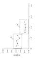
- FIG. 2 shows a two-dimensional graph when the peripheral nerve examination of the subject is normally performed
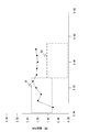
- FIG. 3 shows a two-dimensional graph when the peripheral nerve examination of the subject is not normally performed.
- the intensity (current value) of the stimulus is displayed on the horizontal axis (first axis) of each two-dimensional graph
- the reaction time is displayed on the vertical axis (second axis).
- the horizontal axis may indicate the reaction time and the vertical axis may indicate the stimulation intensity (current value).
- the output unit 14 plots the current value of each stimulus and the measured value of the reaction time, and outputs the data for displaying that each point is connected by a line.
- the intensity of the stimulus is small (when it is below a predetermined threshold)
- C fibers with slow conduction velocity respond
- Fast A ⁇ fibers also respond. Therefore, as shown in FIG. 2, it is normal for the reaction time to drop sharply when the intensity of the stimulus exceeds a certain value.
- the reaction time is about 1.00 to 1.50 seconds until the current value is about 0.20 mA, and the reaction time is about 0.50 seconds or less when the current value exceeds 0.30 mA. Becomes
- the output unit 14 outputs index information indicating at least one of a normal range and an abnormal range of the reaction time.
- the output unit 14 includes a box B1 (first box) that is a region (first region) indicating a normal range of reaction time by C fibers and a region (first region) that indicates a normal range of reaction time by A ⁇ fibers.
- Data for displaying a box B2 (second box) which is two areas) is output.
- the sizes of the boxes B1 and B2 (range of reaction time and range of current value) may be determined based on, for example, inspection results by a sufficient number of subjects.
- the sizes of the boxes B1 and B2 may be determined in consideration of the attributes (age, sex, etc.) of the subject to be examined. Whether or not each measured value is within the range of the box B1 and the box B2 is an index for judging the normality of the test.
- the box B1 and the box B2 are represented by different display effects.
- the box B1 and the box B2 are shown with different line type frame lines, different line color frame lines, or different paint colors.
- the different display effects allow the examiner to easily understand the difference in the stimulated nerves.
- the inspector refers to this two-dimensional graph and determines whether the inspection was performed normally.
- the inspector determines that the inspection has been normally performed when the measured value of the reaction time sharply decreases when the current exceeds a certain current value (FIG. 2).
- the inspector determines that the inspection was not performed normally (abnormal) when the measured value of the reaction time does not change much regardless of the magnitude of the current value (FIG. 3). Further, the inspector determines that the inspection was not normally performed even when the measured value of the reaction time was increased as the current value was increased.
- the measured reaction time is a considerably large time even if the current value stimulates the A ⁇ fibers, and thus the subject may not understand the intention of the test. ..
- the inspector may perform the inspection again and explain the inspection again.
- the inspector appropriately refers to the box B1 and the box B2 that are indicators of normal values in the determination. That is, when each measured value (each plot) is contained in the box B1 and the box B2, the inspector may determine that the inspection is highly likely to have been normally performed.
- the boxes B1 and B2 shown in FIG. 2 and FIG. 3 are a kind of index information for judging whether the reaction time is normal or abnormal.
- the output unit 14 may output the data for displaying the index information by another method.
- the output unit 14 has shown the normal value range of the reaction time in the example of FIG. 2, but may output the data for displaying the abnormal value range instead of the normal value range.
- the output unit 14 may output data for displaying a figure such as a combination of the box B1 and the box B2, and may output data for displaying only a horizontal line separating the normal value range and the abnormal value range of the reaction time. You may output.
- the output unit 14 may display the box B3 in FIG. 4, for example.
- the box B3 is configured to connect a region A1 showing a normal reaction time of the C fiber and a region A2 showing a normal reaction time of the A ⁇ fiber.
- the output unit 14 outputs the data for displaying the relationship of the change in the measured value of the reaction time with respect to the change in the stimulus in a two-dimensional graph, but this is not always the case. Not limited.
- the output unit 14 may output the relationship between the intensity of the stimulus and the measured value of the reaction time to the display 16 in a table format (a table listing a set of the measured values of the intensity of the stimulus and the reaction time). It may be output as an electronic file in the Comma-Separated Values format. In this case, the inspector determines whether or not the inspection is normally performed by referring to the output table or the electronic file.
- the output unit 14 When outputting as a table format or an electronic file, the output unit 14 preferably also outputs the above-mentioned index information. For example, the output unit 14 may output the normal range of the reaction time when the current value is 0.40 mA, as well as the measured value of the reaction time when the current value is 0.40 mA, as shown in the table.
- the output unit 14 preferably outputs a set of measured values of the stimulus intensity and the reaction time for each of a plurality of stimuli, but if it outputs the relationship of the change of the measured values with respect to the change of the stimulus intensity. It may be another one. That is, when the stimulus is performed 10 times, the output unit 14 may output at least the relationship between the intensity and the measurement value of the reaction time regarding the stimulus 2 times or more. For example, the output unit 14 displays (measured value of intensity (eg, 0.15 mA) and reaction time at which C fiber is likely to react) and (measured value of reaction time at intensity (eg, 0.40 mA) at which A ⁇ fiber is likely to react). It suffices that at least two of the above are output, and the inspector can judge the normality of the inspection even with this configuration.
- the peripheral nerve examination apparatus 1 As described above, the A ⁇ fiber and the C fiber have different responsiveness to stimuli and different conduction velocities. Therefore, when a plurality of stimuli with different intensities are given, the test may not be normally performed unless the reaction time according to this property is measured.
- the peripheral nerve examination apparatus 1 is configured to output the relationship of the change in the measured value of the reaction time with respect to the change in the intensity of the stimulus. For example, the peripheral nerve examination apparatus 1 displays the measurement values of the intensity of the stimulus and the reaction time in a two-dimensional graph (FIGS. 2 and 3). The examiner can easily determine whether or not the examination is normally performed (whether or not the examination of the peripheral nerve is normally performed) by referring to the two-dimensional graph.
- the peripheral nerve test apparatus 1 also displays the normal value range of the reaction time (boxes B1 / B2 in the example of FIG. 2) in addition to the measured value, as shown in FIG. The inspector can accurately determine the normality of the test by comparing the measured value and the normal value range.
- the peripheral nerve test apparatus 1A according to the second embodiment is characterized by determining whether or not the test is normally performed and notifying the determination result. Differences between the peripheral nerve examination apparatus 1A according to the second embodiment and the first embodiment will be described below. It should be noted that the processing units given the same names and the same reference numerals as in the first embodiment perform the same operations as those in the first embodiment unless otherwise specified.
- FIG. 5 is a block diagram showing the configuration of the peripheral nerve examination apparatus 1 according to the present embodiment.
- a determination unit 17 is further included in the control unit 11A.
- the determination unit 17 acquires the current value (intensity) of each stimulus controlled by the stimulus control unit 13 and the measurement value of the reaction time for each stimulus measured by the measurement unit 12. Then, the determination unit 17 determines whether or not the examination is normally performed based on the change in the measured value with respect to the change in the intensity of the stimulation (change in the current value). The determination unit 17 notifies the output unit 14 of the determination result.
- the determination unit 17 reads from the hard disk or the like an index of whether the reaction time is normal or abnormal with respect to the strength of the stimulus.
- the index is, for example, the normal value range of the reaction time shown in FIGS. 2 and 3 (information corresponding to the box B1 and the box B2). Then, the determination unit 17 determines that the inspection is normally performed when the measured value of the reaction time for each stimulus is within the normal value range. On the other hand, when the measured value of the reaction time for each stimulus is out of the normal range, the determination unit 17 determines that the test was not performed normally. That is, the determination unit 17 automatically determines the normality of the inspection, which is visually performed by the inspector in FIGS. 2 and 3.
- the determination unit 17 refers to the change in the measured value of the reaction time when the current value is changed. Then, the determination unit 17 determines whether or not there is a point at which the measured value of the reaction time changes abruptly. More specifically, the determination unit 17 determines whether or not there is a portion where the measured value of the reaction time sharply decreases when the intensity of the stimulus is increased. When such a location exists, the determination unit 17 determines that the inspection has been normally performed. On the other hand, the determination unit 17 determines that the inspection is not normally performed when there is no portion where the measured value of the reaction time sharply decreases.
- the determination unit 17 may determine the normality of the inspection by combining the first example and the second example described above. That is, the determination unit 17 determines that the inspection has been normally performed when each measured value is in the normal value range and there is a portion where the measured value changes sharply.
- the output unit 14 outputs the determination result of the determination unit 17 via the display 16 and the speaker 18.
- the output unit 14 may display a warning message indicating that the inspection is not normally performed on the display 16 or output an alarm sound via the speaker 18. Further, the output unit 14 may appropriately display (a message "the examination has been completed normally") or give a voice notification even when the examination is normally performed.
- the output unit 14 may display the two-dimensional graph shown in FIGS. 2 and 3 on the display 16.
- peripheral nerve examination apparatus 1A mechanically (automatically) determines whether or not the examination is normally performed and notifies it. Thereby, the normality of the test can be accurately grasped without being influenced by the subjectivity of the tester.
- FIGS. 1 and 5 are block diagrams focusing on the functional characteristics of the main body unit 10, and FIG. 6 shows an example of the hardware configuration of the main body unit 10.
- the main body unit 10 includes a memory 101, a hard disk drive 102, a CPU 103, an external interface 104, an input unit 15, and a display 16.
- the main body 10 includes a speaker and various electric circuits (not shown). The respective components are connected by a bus 105.
- the external interface 104 is an interface for connecting the operation unit 20 (preferably a switch) to the main body unit 10. A detection signal is input to the external interface 104 from the operation unit 20.
- the hard disk 102 is a secondary storage device in the main body 10 and stores various kinds of information.
- the hard disk 102 does not necessarily have to be built in the main body 10, and may be removable from the main body 10.
- the hard disk 102 stores various data and programs necessary for executing the above-mentioned operations.
- a CPU (Central Processing Unit) 103 develops on the memory 101 data and programs necessary for executing various processes of the control units 11 and 11A (measurement unit 12, stimulation control unit 13, output unit 14) described above. Execute each instruction contained in the program. At least a part of various processes of the control units 11 and 11A (measurement unit 12, stimulation control unit 13, output unit 14) may be realized by a peripheral circuit (not shown) or the like.
- Non-transitory computer readable media include various types of tangible storage media.
- Examples of non-transitory computer-readable media include magnetic recording media (eg, flexible disk, magnetic tape, hard disk drive), magneto-optical recording media (eg, magneto-optical disk), CD-ROM (Read Only Memory), CD-R, It includes a CD-R / W and a semiconductor memory (for example, mask ROM, PROM (Programmable ROM), EPROM (Erasable PROM), flash ROM, RAM (random access memory)).
- the program may be supplied to the computer by various types of transitory computer readable media. Examples of transitory computer-readable media include electrical signals, optical signals, and electromagnetic waves.
- the transitory computer-readable medium can supply the program to the computer via a wired communication path such as an electric wire and an optical fiber, or a wireless communication path.
Landscapes
- Health & Medical Sciences (AREA)
- Life Sciences & Earth Sciences (AREA)
- Neurology (AREA)
- Engineering & Computer Science (AREA)
- Animal Behavior & Ethology (AREA)
- Public Health (AREA)
- Neurosurgery (AREA)
- Veterinary Medicine (AREA)
- General Health & Medical Sciences (AREA)
- Physics & Mathematics (AREA)
- Surgery (AREA)
- Biophysics (AREA)
- Pathology (AREA)
- Biomedical Technology (AREA)
- Heart & Thoracic Surgery (AREA)
- Medical Informatics (AREA)
- Molecular Biology (AREA)
- Educational Technology (AREA)
- Developmental Disabilities (AREA)
- Social Psychology (AREA)
- Hospice & Palliative Care (AREA)
- Psychology (AREA)
- Child & Adolescent Psychology (AREA)
- Psychiatry (AREA)
- Physiology (AREA)
- Measurement And Recording Of Electrical Phenomena And Electrical Characteristics Of The Living Body (AREA)
Abstract
La présente invention concerne un dispositif d'examen de nerf périphérique (1) évaluant un nerf d'un sujet sur la base d'une expression par le sujet d'une perception de stimulation. Une unité de commande de stimulation (13) commande une pluralité de stimulations d'intensité variable qui sont communiquées au sujet. Une unité de mesure (12) obtient une valeur mesurée du temps de réaction du sujet à chacune de la pluralité de stimulations. Une unité de sortie (14) délivre une relation entre les valeurs mesurées et l'intensité de la pluralité de stimulations.
Priority Applications (2)
| Application Number | Priority Date | Filing Date | Title |
|---|---|---|---|
| PCT/JP2018/041959 WO2020100209A1 (fr) | 2018-11-13 | 2018-11-13 | Dispositif d'examen de nerf périphérique, méthode d'examen de nerf périphérique, et programme |
| EP18940272.0A EP3881764A4 (fr) | 2018-11-13 | 2018-11-13 | Dispositif d'examen de nerf périphérique, méthode d'examen de nerf périphérique, et programme |
Applications Claiming Priority (1)
| Application Number | Priority Date | Filing Date | Title |
|---|---|---|---|
| PCT/JP2018/041959 WO2020100209A1 (fr) | 2018-11-13 | 2018-11-13 | Dispositif d'examen de nerf périphérique, méthode d'examen de nerf périphérique, et programme |
Publications (1)
| Publication Number | Publication Date |
|---|---|
| WO2020100209A1 true WO2020100209A1 (fr) | 2020-05-22 |
Family
ID=70730419
Family Applications (1)
| Application Number | Title | Priority Date | Filing Date |
|---|---|---|---|
| PCT/JP2018/041959 Ceased WO2020100209A1 (fr) | 2018-11-13 | 2018-11-13 | Dispositif d'examen de nerf périphérique, méthode d'examen de nerf périphérique, et programme |
Country Status (2)
| Country | Link |
|---|---|
| EP (1) | EP3881764A4 (fr) |
| WO (1) | WO2020100209A1 (fr) |
Citations (3)
| Publication number | Priority date | Publication date | Assignee | Title |
|---|---|---|---|---|
| JP2010088802A (ja) * | 2008-10-10 | 2010-04-22 | National Institutes Of Natural Sciences | 痛覚神経刺激装置 |
| JP2011164879A (ja) | 2010-02-09 | 2011-08-25 | National Institutes Of Natural Sciences | 痛覚神経刺激装置 |
| JP2017201671A (ja) | 2016-05-07 | 2017-11-09 | 株式会社 イーアールディー | 熱伝導シートの配設構造及び配設方法 |
Family Cites Families (4)
| Publication number | Priority date | Publication date | Assignee | Title |
|---|---|---|---|---|
| JPWO2006059430A1 (ja) * | 2004-11-30 | 2008-06-05 | 大学共同利用機関法人自然科学研究機構 | 痛覚神経刺激用電極 |
| JP5661555B2 (ja) * | 2011-05-10 | 2015-01-28 | 日本光電工業株式会社 | 交感神経皮膚反応測定装置 |
| DE102012111733A1 (de) * | 2012-12-03 | 2014-06-05 | Klaus Glaunsinger | Verfahren und Vorrichtung zur Überprüfung der Validität von Reaktionszeiten einer Person |
| WO2016146758A1 (fr) * | 2015-03-19 | 2016-09-22 | Aalborg Universitet | Évaluation de l'excitabilité de fibres nerveuses |
-
2018
- 2018-11-13 WO PCT/JP2018/041959 patent/WO2020100209A1/fr not_active Ceased
- 2018-11-13 EP EP18940272.0A patent/EP3881764A4/fr active Pending
Patent Citations (3)
| Publication number | Priority date | Publication date | Assignee | Title |
|---|---|---|---|---|
| JP2010088802A (ja) * | 2008-10-10 | 2010-04-22 | National Institutes Of Natural Sciences | 痛覚神経刺激装置 |
| JP2011164879A (ja) | 2010-02-09 | 2011-08-25 | National Institutes Of Natural Sciences | 痛覚神経刺激装置 |
| JP2017201671A (ja) | 2016-05-07 | 2017-11-09 | 株式会社 イーアールディー | 熱伝導シートの配設構造及び配設方法 |
Non-Patent Citations (6)
| Title |
|---|
| FUMIAKI KUSAKA, HIROFUMI TOKUYAMA: "Quantitative evaluation of peripheral sensory nerve improvement by AC magnetic therapy in various pain diseases Examination of current perception threshold of each peripheral sensory nerve fiber by Neurometer NS3000", THE JOURNAL OF THE JAPAN MEDICAL CONFERENCE ON MAGNETISM, vol. 321, 1 January 2007 (2007-01-01), JP, pages 25 - 39, XP009529332 * |
| KOJI INUIRYUSUKE KAKIGI: "Pain perception in humans: use of intraepidermal electrical stimulation", J NEUROL NEUROSURG PSYCHIATRY, vol. 83, 2012, pages 551 - 556, XP009162149, DOI: 10.1136/jnnp-2011-301484 |
| MARK J. ZYLKAFRANK L. RICEDAVID J. ANDERSON: "Topographically Distinct Epidermal Nociceptive Cricuits Revealed by Axonal Tracers Targeted to Mrgprd", NEURON, vol. 45, 6 January 2005 (2005-01-06), pages 17 - 25 |
| MARTINS , HENRIQUE RESENDE ET AL.: "Current perception threshold and reaction time in the assessment of sensory peripheral nerve fibers through sinusoidal electrical stimulation at different frequencies", BRAZILIAN JOURNAL OF BIOMEDICAL ENGINEERING, vol. 29, no. 3, 2013, pages 278 - 285, XP055563737, DOI: 10.4322/rbeb.2013.028 * |
| MAXIM CHURYUKANOVLEON PLAGHKIVALERY LEGRAINANDRE MOURAUX: "Thermal Detection Thresholds of Aδ- and C-Fibre Afferents Activated by Brief Co2 Laser Pulses Applied onto the Human Hairy Skin", PLOS ONE, vol. 7, no. 4, pages e35817 |
| See also references of EP3881764A4 |
Also Published As
| Publication number | Publication date |
|---|---|
| EP3881764A4 (fr) | 2022-07-06 |
| EP3881764A1 (fr) | 2021-09-22 |
Similar Documents
| Publication | Publication Date | Title |
|---|---|---|
| US20150258995A1 (en) | Method and Assistance System for Assisting a Driver of a Motor Vehicle as well as Measuring Method and Measuring System for Determining a Mental State of a Driver of a Motor Vehicle | |
| JP6621538B2 (ja) | 痛み推定装置及び痛み推定方法並びに痛みの分類 | |
| US10398371B2 (en) | Pain measuring device | |
| Sanchez et al. | Impedance alterations in healthy and diseased mice during electrically induced muscle contraction | |
| EP3698711B1 (fr) | Système de mesure d'électroencéphalogramme, système de support de rééducation, procédé de commande de système de mesure d'électroencéphalogramme, programme et support d'enregistrement non-transitoire | |
| KR20160041748A (ko) | P300 뇌파를 측정하고 분석하는 장치 | |
| CN114431863B (zh) | 用于测量电极接触阻抗的系统及阻抗测量方法 | |
| US12076152B2 (en) | Electroencephalogram decision system, electroencephalogram decision method, program, and non-transitory storage medium | |
| JP2008212465A (ja) | 痛み測定装置、痛み測定装置の制御方法、刺激電流付与装置および刺激電流付与装置の制御方法 | |
| Adenekan et al. | Feasibility of smartphone vibrations as a sensory diagnostic tool | |
| JP7095971B2 (ja) | 末梢神経検査装置、末梢神経検査方法、及びプログラム | |
| WO2020100209A1 (fr) | Dispositif d'examen de nerf périphérique, méthode d'examen de nerf périphérique, et programme | |
| US20160038750A1 (en) | Defibrillator and method of controlling defibrillator | |
| Milici et al. | System for highlighting the emotional states, used in assessing the teaching methods | |
| KR20150122936A (ko) | 압통계를 사용하여 인가한 압력자극 신호와 피부전기활동 신호 계측에 의한 통증 환자의 통증유발점 검출 시스템 | |
| US11484237B2 (en) | Physiological information measurement apparatus and program | |
| US20180092566A1 (en) | Method for determining the perceptiveness of a subject | |
| WO2015047147A4 (fr) | Dispositif utilisé pour évaluer le risque de suicide | |
| KR20120096846A (ko) | 안면 신경 모니터링 장치 및 방법 | |
| JP2019118536A (ja) | 生体機能計測解析システム、生体機能計測解析プログラム及び生体機解析方法 | |
| JPH04174642A (ja) | 神経、筋機能検査装置 | |
| JP2018191773A (ja) | 痛み測定装置および痛み測定方法 | |
| JP7740536B2 (ja) | 嗅覚障害検知装置、嗅覚障害検知方法及び嗅覚障害検知プログラム | |
| KR101635994B1 (ko) | 촉각경험 표준화를 위한 erp기반 촉각자극 조절 방법 및 시스템 | |
| WO2009123498A1 (fr) | Dispositif de contrôle et d’estimation de processus physiologiques |
Legal Events
| Date | Code | Title | Description |
|---|---|---|---|
| 121 | Ep: the epo has been informed by wipo that ep was designated in this application |
Ref document number: 18940272 Country of ref document: EP Kind code of ref document: A1 |
|
| NENP | Non-entry into the national phase |
Ref country code: DE |
|
| ENP | Entry into the national phase |
Ref document number: 2018940272 Country of ref document: EP Effective date: 20210614 |
|
| NENP | Non-entry into the national phase |
Ref country code: JP |