WO2020105355A1 - 副室式ディーゼル機関 - Google Patents
副室式ディーゼル機関Info
- Publication number
- WO2020105355A1 WO2020105355A1 PCT/JP2019/041623 JP2019041623W WO2020105355A1 WO 2020105355 A1 WO2020105355 A1 WO 2020105355A1 JP 2019041623 W JP2019041623 W JP 2019041623W WO 2020105355 A1 WO2020105355 A1 WO 2020105355A1
- Authority
- WO
- WIPO (PCT)
- Prior art keywords
- injection
- fuel
- main injection
- diesel engine
- injector
- Prior art date
- Legal status (The legal status is an assumption and is not a legal conclusion. Google has not performed a legal analysis and makes no representation as to the accuracy of the status listed.)
- Ceased
Links
Images


Classifications
-
- F—MECHANICAL ENGINEERING; LIGHTING; HEATING; WEAPONS; BLASTING
- F02—COMBUSTION ENGINES; HOT-GAS OR COMBUSTION-PRODUCT ENGINE PLANTS
- F02B—INTERNAL-COMBUSTION PISTON ENGINES; COMBUSTION ENGINES IN GENERAL
- F02B19/00—Engines characterised by precombustion chambers
- F02B19/12—Engines characterised by precombustion chambers with positive ignition
-
- F—MECHANICAL ENGINEERING; LIGHTING; HEATING; WEAPONS; BLASTING
- F02—COMBUSTION ENGINES; HOT-GAS OR COMBUSTION-PRODUCT ENGINE PLANTS
- F02B—INTERNAL-COMBUSTION PISTON ENGINES; COMBUSTION ENGINES IN GENERAL
- F02B19/00—Engines characterised by precombustion chambers
- F02B19/14—Engines characterised by precombustion chambers with compression ignition
-
- F—MECHANICAL ENGINEERING; LIGHTING; HEATING; WEAPONS; BLASTING
- F02—COMBUSTION ENGINES; HOT-GAS OR COMBUSTION-PRODUCT ENGINE PLANTS
- F02B—INTERNAL-COMBUSTION PISTON ENGINES; COMBUSTION ENGINES IN GENERAL
- F02B19/00—Engines characterised by precombustion chambers
- F02B19/08—Engines characterised by precombustion chambers the chamber being of air-swirl type
-
- F—MECHANICAL ENGINEERING; LIGHTING; HEATING; WEAPONS; BLASTING
- F02—COMBUSTION ENGINES; HOT-GAS OR COMBUSTION-PRODUCT ENGINE PLANTS
- F02B—INTERNAL-COMBUSTION PISTON ENGINES; COMBUSTION ENGINES IN GENERAL
- F02B19/00—Engines characterised by precombustion chambers
- F02B19/10—Engines characterised by precombustion chambers with fuel introduced partly into pre-combustion chamber, and partly into cylinder
- F02B19/1019—Engines characterised by precombustion chambers with fuel introduced partly into pre-combustion chamber, and partly into cylinder with only one pre-combustion chamber
- F02B19/108—Engines characterised by precombustion chambers with fuel introduced partly into pre-combustion chamber, and partly into cylinder with only one pre-combustion chamber with fuel injection at least into pre-combustion chamber, i.e. injector mounted directly in the pre-combustion chamber
- F02B19/1085—Engines characterised by precombustion chambers with fuel introduced partly into pre-combustion chamber, and partly into cylinder with only one pre-combustion chamber with fuel injection at least into pre-combustion chamber, i.e. injector mounted directly in the pre-combustion chamber controlling fuel injection
-
- F—MECHANICAL ENGINEERING; LIGHTING; HEATING; WEAPONS; BLASTING
- F02—COMBUSTION ENGINES; HOT-GAS OR COMBUSTION-PRODUCT ENGINE PLANTS
- F02B—INTERNAL-COMBUSTION PISTON ENGINES; COMBUSTION ENGINES IN GENERAL
- F02B19/00—Engines characterised by precombustion chambers
- F02B19/16—Chamber shapes or constructions not specific to sub-groups F02B19/02 - F02B19/10
- F02B19/18—Transfer passages between chamber and cylinder
-
- F—MECHANICAL ENGINEERING; LIGHTING; HEATING; WEAPONS; BLASTING
- F02—COMBUSTION ENGINES; HOT-GAS OR COMBUSTION-PRODUCT ENGINE PLANTS
- F02D—CONTROLLING COMBUSTION ENGINES
- F02D41/00—Electrical control of supply of combustible mixture or its constituents
- F02D41/30—Controlling fuel injection
- F02D41/38—Controlling fuel injection of the high pressure type
- F02D41/40—Controlling fuel injection of the high pressure type with means for controlling injection timing or duration
- F02D41/401—Controlling injection timing
-
- F—MECHANICAL ENGINEERING; LIGHTING; HEATING; WEAPONS; BLASTING
- F02—COMBUSTION ENGINES; HOT-GAS OR COMBUSTION-PRODUCT ENGINE PLANTS
- F02D—CONTROLLING COMBUSTION ENGINES
- F02D41/00—Electrical control of supply of combustible mixture or its constituents
- F02D41/30—Controlling fuel injection
- F02D41/38—Controlling fuel injection of the high pressure type
- F02D41/40—Controlling fuel injection of the high pressure type with means for controlling injection timing or duration
- F02D41/402—Multiple injections
- F02D41/403—Multiple injections with pilot injections
-
- F—MECHANICAL ENGINEERING; LIGHTING; HEATING; WEAPONS; BLASTING
- F02—COMBUSTION ENGINES; HOT-GAS OR COMBUSTION-PRODUCT ENGINE PLANTS
- F02M—SUPPLYING COMBUSTION ENGINES IN GENERAL WITH COMBUSTIBLE MIXTURES OR CONSTITUENTS THEREOF
- F02M55/00—Fuel-injection apparatus characterised by their fuel conduits or their venting means; Arrangements of conduits between fuel tank and pump F02M37/00
- F02M55/02—Conduits between injection pumps and injectors, e.g. conduits between pump and common-rail or conduits between common-rail and injectors
- F02M55/025—Common rails
-
- F—MECHANICAL ENGINEERING; LIGHTING; HEATING; WEAPONS; BLASTING
- F02—COMBUSTION ENGINES; HOT-GAS OR COMBUSTION-PRODUCT ENGINE PLANTS
- F02P—IGNITION, OTHER THAN COMPRESSION IGNITION, FOR INTERNAL-COMBUSTION ENGINES; TESTING OF IGNITION TIMING IN COMPRESSION-IGNITION ENGINES
- F02P19/00—Incandescent ignition, e.g. during starting of internal combustion engines; Combination of incandescent and spark ignition
-
- F—MECHANICAL ENGINEERING; LIGHTING; HEATING; WEAPONS; BLASTING
- F02—COMBUSTION ENGINES; HOT-GAS OR COMBUSTION-PRODUCT ENGINE PLANTS
- F02P—IGNITION, OTHER THAN COMPRESSION IGNITION, FOR INTERNAL-COMBUSTION ENGINES; TESTING OF IGNITION TIMING IN COMPRESSION-IGNITION ENGINES
- F02P19/00—Incandescent ignition, e.g. during starting of internal combustion engines; Combination of incandescent and spark ignition
- F02P19/02—Incandescent ignition, e.g. during starting of internal combustion engines; Combination of incandescent and spark ignition electric, e.g. layout of circuits of apparatus having glowing plugs
- F02P19/026—Glow plug actuation during engine operation
-
- F—MECHANICAL ENGINEERING; LIGHTING; HEATING; WEAPONS; BLASTING
- F02—COMBUSTION ENGINES; HOT-GAS OR COMBUSTION-PRODUCT ENGINE PLANTS
- F02P—IGNITION, OTHER THAN COMPRESSION IGNITION, FOR INTERNAL-COMBUSTION ENGINES; TESTING OF IGNITION TIMING IN COMPRESSION-IGNITION ENGINES
- F02P5/00—Advancing or retarding ignition; Control therefor
- F02P5/04—Advancing or retarding ignition; Control therefor automatically, as a function of the working conditions of the engine or vehicle or of the atmospheric conditions
- F02P5/145—Advancing or retarding ignition; Control therefor automatically, as a function of the working conditions of the engine or vehicle or of the atmospheric conditions using electrical means
- F02P5/15—Digital data processing
-
- Y—GENERAL TAGGING OF NEW TECHNOLOGICAL DEVELOPMENTS; GENERAL TAGGING OF CROSS-SECTIONAL TECHNOLOGIES SPANNING OVER SEVERAL SECTIONS OF THE IPC; TECHNICAL SUBJECTS COVERED BY FORMER USPC CROSS-REFERENCE ART COLLECTIONS [XRACs] AND DIGESTS
- Y02—TECHNOLOGIES OR APPLICATIONS FOR MITIGATION OR ADAPTATION AGAINST CLIMATE CHANGE
- Y02T—CLIMATE CHANGE MITIGATION TECHNOLOGIES RELATED TO TRANSPORTATION
- Y02T10/00—Road transport of goods or passengers
- Y02T10/10—Internal combustion engine [ICE] based vehicles
- Y02T10/12—Improving ICE efficiencies
-
- Y—GENERAL TAGGING OF NEW TECHNOLOGICAL DEVELOPMENTS; GENERAL TAGGING OF CROSS-SECTIONAL TECHNOLOGIES SPANNING OVER SEVERAL SECTIONS OF THE IPC; TECHNICAL SUBJECTS COVERED BY FORMER USPC CROSS-REFERENCE ART COLLECTIONS [XRACs] AND DIGESTS
- Y02—TECHNOLOGIES OR APPLICATIONS FOR MITIGATION OR ADAPTATION AGAINST CLIMATE CHANGE
- Y02T—CLIMATE CHANGE MITIGATION TECHNOLOGIES RELATED TO TRANSPORTATION
- Y02T10/00—Road transport of goods or passengers
- Y02T10/10—Internal combustion engine [ICE] based vehicles
- Y02T10/40—Engine management systems
Definitions
- the present invention relates to a sub-chamber diesel engine including a main combustion chamber and a sub combustion chamber that are communicated with each other by a communication hole.
- a sub-chamber type diesel engine having a main combustion chamber and a sub combustion chamber that are communicated with each other by a communication hole is known.
- a general swirl chamber type sub-chamber diesel engine includes a main combustion chamber formed on a piston, a sub combustion chamber communicating with the main combustion chamber through a communication hole, and an injector for injecting fuel into the sub combustion chamber.
- the air enters the auxiliary combustion chamber from the main combustion chamber side through the communication hole in the compression stroke to generate a strong vortex flow in the auxiliary combustion chamber.
- fuel is injected into the auxiliary combustion chamber in which the vortex flow is generated to form an air-fuel mixture, and compression ignition is performed near the compression top dead center. Start burning.
- the combustion energy of the combustion gas generated in the auxiliary combustion chamber the combustion gas is introduced from the auxiliary combustion chamber into the main combustion chamber through the communication hole to complete combustion while driving the piston to obtain power ( See, for example, Patent Documents 1 and 2.
- premixed compression ignition combustion in which a mixture is formed in advance and compression ignition is performed.
- the ignition timing of the fuel may be too early and the thermal efficiency may be significantly reduced depending on the operating state. Therefore, it has been proposed to delay the ignition timing by using a fuel that does not easily self-ignite or by reducing the compression ratio.
- changing the fuel or reducing the compression ratio of the engine narrows the conditions for adopting the engine and reduces the performance of the engine, and cannot be easily adopted.
- the present invention has been made in view of the above facts, and its main technical problem is to provide a sub-chamber diesel engine with excellent thermal efficiency that can appropriately control the ignition timing of the fuel supplied to the sub-combustion chamber. Especially.
- a sub-chamber diesel engine including a main combustion chamber and a sub-combustion chamber which are communicated by a communication hole
- fuel is injected into the sub-combustion chamber at an arbitrary timing.
- An electrically driven injector a fuel passage pipe connected to a fuel inlet of the injector, a fuel pump for supplying fuel to the fuel passage pipe, an engine operating state detecting means for detecting an engine operating state, and a control
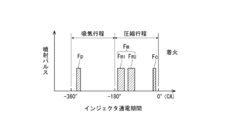
- the control means performs preliminary fuel injection in the first half of the intake stroke, main injection is performed during the compression stroke, and ignition control injection is performed near the compression top dead center after the main injection.
- a sub-chamber diesel engine to perform is provided.
- the center axis of the fuel sprayed from the injector and the center axis of the communication hole are preferably offset.
- a glow plug is provided in the auxiliary combustion chamber, and the control means does not perform the preliminary injection when the exhaust gas temperature detected by the operating state detection means is equal to or lower than a predetermined temperature, It is preferable to operate the glow plug to heat the auxiliary combustion chamber.
- the control means controls the injection start timing, the injection amount, and the injection pressure of the main injection injected from the injector based on the operating state detected by the operating state detecting means, and is calculated by the controlling means. It is preferable to divide the main injection into a predetermined number of times and inject according to the injection amount of the main injection and the injection pressure required at that time.
- the control means changes the injection start timing of the main injection from the top dead center side to the bottom dead center of the compression stroke as the engine rotation speed detected by the operating state detection means changes from low rotation speed to high rotation speed.
- the angle may be advanced to the point side.
- the injection pressure injected from the injector is preferably set to 8 MPa to 40 MPa.
- a sub-chamber diesel engine with excellent thermal efficiency that can appropriately control the ignition timing of the fuel supplied to the sub-combustion chamber is provided.
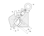
- FIG. 2 is a schematic view showing an arrangement of a sub combustion chamber, an injector, and a glow plug of the sub chamber type diesel engine shown in FIG. 1.
- FIG. 5 is an explanatory diagram for explaining a process of calculating a main injection start timing according to the calculation flow shown in FIG. 4.
- FIG. 1 shows an overall schematic view of a sub-chamber type diesel engine 1 including a main combustion chamber and a sub combustion chamber.
- the diesel engine 1 includes an engine body 2, a fuel supply system 40, an intake system 50, an exhaust system 60, a supercharger 70, an EGR system 80, and control means (engine ECU) 100.
- the engine body 2 includes a cylinder block 3, a cylinder head 4, a piston 5, an intake port 6, an intake valve 7, an exhaust port 8 (shown by a broken line), and an exhaust valve (not shown).
- the exhaust valve is arranged in parallel with the intake valve 7 in a direction perpendicular to the plane of the drawing, and is opened and closed together with the intake valve 7 by a valve mechanism (not shown).
- the cylinder head 4 has an auxiliary combustion chamber 10 formed in a substantially spherical shape.
- the main combustion chamber 14 is formed between the top surface 5a of the piston 5 sliding in the cylinder 3a and the lower surface 4a of the cylinder head 4.
- the auxiliary combustion chamber 10 communicates with the main combustion chamber 14 via a communication hole 12 that is inclined with respect to the sliding direction of the piston 5 shown by the arrow.
- the auxiliary combustion chamber 10 is provided with an injector 20 for injecting fuel into the auxiliary combustion chamber 10 and a glow plug 25 for heating the inside of the auxiliary combustion chamber 10.
- a fuel passage pipe 30 is connected to the injector 20 so as to accumulate the pressure of the fuel and supply the fuel to the injector 20.
- Fuel is supplied to the fuel passage pipe 30 by the fuel supply system 40.
- the fuel supply system 40 includes a fuel pump 41, a fuel supply pipe 42, a pressure feed control valve 43, and a fuel tank 44.
- the fuel pump 41 is driven by the crankshaft 9 of the diesel engine 1 via a power transmission mechanism (not shown), and supplies the fuel sucked by the fuel pump 41 from the fuel tank 44 to the fuel passage pipe 30 via the fuel supply pipe 42. To do.
- the pumping amount control valve 43 is electrically operated, has a function of controlling the amount of fuel sucked by the fuel pump 41, which is relieved to the fuel tank side, and supplies the fuel from the fuel pump 41 to the fuel passage pipe 30. The amount of fuel can be adjusted.
- the diesel engine 1 is a so-called multi-cylinder engine including a plurality of cylinders 3a, and the plurality of cylinders 3a are arranged in series with the cylinder block 3.
- a sub combustion chamber 10 is formed corresponding to each cylinder 3a, and an injector 20 and a glow plug 25 are provided for each sub combustion chamber 10.
- Each injector 20 is connected to a common fuel passage pipe 30, and injects fuel into the auxiliary combustion chamber 10 at the fuel pressure accumulated in the fuel passage pipe 30. That is, the fuel pressure in the fuel passage pipe 30 becomes the injection pressure when the fuel is injected from the injector 20 into the auxiliary combustion chamber 10.
- the injector 20 is a so-called in-valve type injector, whose operation is electrically driven by an electromagnetic solenoid (not shown), and injects fuel at an arbitrary timing based on an electric signal sent to the injector 20. can do.
- the fuel passage pipe 30 is a tubular member extending in a direction perpendicular to the paper surface of FIG. 1, and has an injector mounting boss 32 into which the fuel inlet of the injector 20 is inserted.
- the injector mounting bosses 32 are formed at equal intervals in the axial direction of the fuel passage pipe 30 according to the number of the injectors 20 to be mounted.
- the intake system 50 introduces air (outside air) into the intake port 6 of the diesel engine 1.
- the intake system 50 includes an intake passage 52, and the intake passage 52 includes a compressor 72 of the supercharger 70 and an intake cooler (intercooler) 54.
- the intake passage 52 may be provided with an intake control valve that adjusts the intake amount.
- the exhaust system 60 discharges exhaust gas emitted from the diesel engine 1 to the outside of the diesel engine 1.
- the exhaust system 60 includes an exhaust passage 62.
- a turbine 74 of the supercharger 70 is provided in the exhaust passage 62.
- the exhaust passage 62 is connected to the exhaust port 8 of the diesel engine 1.
- the EGR system 80 includes an EGR passage 81 that introduces a part of the exhaust gas flowing through the exhaust passage 62 into the intake port 6 of the diesel engine 1 as EGR gas.
- the upstream end of the EGR passage 81 is connected to the exhaust passage 62.
- the downstream end of the EGR passage 81 is connected to the upstream side of the intake port 6 of the intake passage 52.
- the EGR passage 81 is provided with an EGR gas cooler 82 that cools the EGR gas.
- the EGR passage 81 is provided with a cooler bypass passage 84 for bypassing the EGR gas cooler 82 and allowing EGR gas to flow to the intake passage 52 side.
- the cooler bypass passage 84 is provided with a bypass amount adjustment valve 86 that adjusts the amount of EGR gas to be bypassed.
- An EGR gas amount adjustment valve 88 is provided in the EGR passage 81 downstream of the EGR gas cooler 82 (on the intake passage 52 side). By controlling the opening degree of the EGR gas amount adjustment valve 88, the amount of EGR gas introduced into the intake port 6 via the intake passage 52 can be adjusted.
- the diesel engine 1 is provided with an engine ECU 100 as a control means for controlling the diesel engine 1 as a whole.
- the engine ECU 100 is composed of a computer, and a central processing unit (CPU) that performs arithmetic processing according to a control program, a read-only memory (ROM) that stores a control program and the like, a detected value detected, a calculation result, etc. temporarily. It is provided with a readable / writable random access memory (RAM) for storing, an input interface, and an output interface (details are not shown).
- CPU central processing unit
- ROM read-only memory
- RAM readable / writable random access memory
- the engine ECU 100 detects the operating state of the diesel engine 1, and in response to the detected operating state, in accordance with a control program stored in advance in the ROM, the injection timing of the fuel supplied from the injector 20 to the auxiliary combustion chamber 10, The injection pressure, the injection amount, the number of injections, the EGR gas amount introduced into the intake port, etc. are controlled.
- the engine operating state detecting means for detecting the operating state of the diesel engine 1 described above.
- the engine operating state detecting means can be configured by including various sensors as shown in FIG.
- the various sensors include, for example, a fuel passage pipe pressure sensor 101 that detects the pressure of fuel accumulated in the fuel passage pipe 30, a crank angle sensor 102 that detects the angular position of the crankshaft 9, and an exhaust port 8.
- Exhaust gas temperature sensor 103 for detecting the exhaust gas temperature (for example, exhaust manifold internal temperature)
- EGR gas temperature sensor 104 for detecting the temperature of the exhaust gas branched from the exhaust passage 62 and introduced into the EGR passage 81, accelerator lever opening degree A sensor 105 can be included.
- the various sensors described above are connected to the engine ECU 100, and the values detected by the various sensors are input to the engine ECU 100.
- the engine ECU 100 also calculates the reference angular position of the reference cylinder and the engine rotation speed based on the signal from the crank angle sensor 102.
- an intake air amount sensor that detects the actual intake air amount taken into the intake port 6
- an intake pressure sensor that detects the pressure in the intake port 6, and an atmospheric pressure
- Various other sensors such as an atmospheric pressure sensor and a cooling water temperature sensor are provided (not shown).
- the operating state detection means may separately include a reference position sensor that detects the reference angular position of the reference cylinder and an engine rotation speed sensor that detects the engine rotation speed.
- the operating state detecting means also includes means for calculating an estimated operating state value by a control program stored in the engine ECU 100.
- the operation of the engine ECU 100 will be described with reference to FIGS. 2 to 6.
- the engine ECU 100 appropriately calculates the injection amount of fuel injected from the injector 20, the injection pressure, the injection start timing, and the number of injections based on the operating state detected by the operating state detecting means described above. Then, as shown in FIG. 2, the preliminary fuel injection Fp is performed in the first half of the intake stroke, the main injection Fm is performed during the compression stroke, and after the main injection Fm, the ignition control injection Fc near the compression top dead center. Carry out.
- FIG. 2 the preliminary fuel injection Fp is performed in the first half of the intake stroke
- the main injection Fm is performed during the compression stroke
- the ignition control injection Fc near the compression top dead center. Carry out.
- the vertical axis represents the generation of the injection pulse for driving the injector 20
- the horizontal axis represents the energization of the injector 20 indicated by the crank angle (CA) with the compression top dead center as the reference (0 °).
- CA crank angle
- This energization period corresponds to the injection period in which fuel is injected from the injector 20 into the auxiliary combustion chamber 10.
- the fuel injection control of the present embodiment will be described more specifically below.
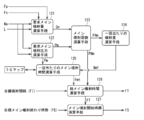
- FIG. 3 shows a calculation flow executed by the engine ECU 100.
- the engine ECU 100 requests the required load L in consideration of the engine rotation speed Ne detected by the crank angle sensor 102, the lever opening of the accelerator lever opening sensor 105, the work load on the diesel engine 1, and the like.
- the main injection quantity is calculated by subtracting the pre-injection Fp and the fuel quantity supplied by the ignition control injection Fc from the total injection quantity required by the diesel engine 1 to obtain the required main injection quantity Qm.
- the injection amount injected by the preliminary injection Fp and the ignition control injection Fc may be a fixed value or a value that is increased or decreased depending on the operating state. In any case, the required main injection amount Qm is set to be a relatively large value with respect to the injection amounts implemented by the preliminary injection Fp and the ignition control injection Fc.
- the engine rotation speed Ne and the required load L are also input to the required main injection pressure calculation means 122, and the injection pressure of the main injection required by the diesel engine 1 is input. Is output as the required main injection pressure Pm.
- the required main injection pressure Pm is set to be low when the required load L is low and the engine rotation speed Ne is low, and conversely is set to be high when the required load L is high and the engine rotation speed Ne is high. It is set by a map or the like (not shown). If the required main injection pressure Pm is output, the required main injection pressure Pm is set as the target fuel pressure of the fuel passage pipe 30, and the detected value of the fuel passage pipe pressure sensor 101 installed in the fuel passage pipe 30.
- the pressure feed control valve 43 of the fuel pump 41 is controlled based on As a result, the pressure in the fuel passage pipe 30 is constantly adjusted within a predetermined range near the required main injection pressure Pm.
- the required main injection amount Qm and the required main injection pressure Pm are input to the main injection number calculation means 123, and the main injection Fm is given a predetermined number of times.
- the main injection number FNm for dividing and injecting is calculated.
- the required main injection amount Qm and the required main injection pressure Pm input to the main injection number calculation means 123 are first input to the required main injection time calculation means 123a.
- the required main injection time calculation means 123a refers to a TQ map as shown on the right side of the drawing.
- the TQ map is recorded in the engine ECU 100 in advance, and the injector 20 set corresponding to the injection amount (mm 3 ) injected from the injector 20 and the pressure (P1 to P4: MPa) of the fuel passage pipe 30 is set.
- Is a map for specifying the energization time of, that is, the injection time ( ⁇ s), and is set by an experiment or the like.
- the injection time for realizing the amount Qm, that is, the required main injection time FmT is obtained.
- the required main injection time FmT is obtained, the required main injection time FmT is input together with the required main injection pressure Pm to the spray tip reaching distance calculating means 123b, and the injector 20 is injected by referring to a map (not shown).
- the spray tip reaching distance FD of the spray to be calculated is calculated.
- the spray tip reaching distance FD is a value that increases as the required main injection pressure Pm is higher and the required main injection time FmT is longer.
- the distance that the tip of the spray actually reaches is also affected by the diameter and shape of the nozzle formed at the tip of the injector 20. Therefore, the map for determining the spray tip reaching distance FD is for each injector 20 such as an experiment. It is formulated by.
- the spray tip reaching distance FD is input to the main injection number calculation means 123c and the main injection number FNm is calculated.
- the spray tip reaching distance limit value FDL is referred to.
- the spray tip reaching distance limit value FDL will be described with reference to FIG.
- the spray tip reaching distance limit value FDL is not necessarily limited to using the distance from the tip portion of the injector 20 to the wall surface 10a of the opposing auxiliary combustion chamber 10 as it is. Considering the influence on the combustion when the spray F adheres to the wall surface 10a of the auxiliary combustion chamber 10, it is set to a value slightly smaller than the distance from the tip of the injector 20 to the opposite wall surface 10a of the auxiliary combustion chamber 10. It is also possible to set it to a slightly larger value.
- the spray tip reaching distance limit value FDL set as described above is compared with the spray tip reaching distance FD, and when the spray tip reaching distance FD is smaller than the spray tip reaching distance limit value FDL, the requested main injection Even if the quantity Qm is injected once, the fuel injected from the injector 20 does not reach the wall surface of the auxiliary combustion chamber 10, so the number of main injections FNm is set to once. Further, if the spray tip reaching distance FD is equal to or greater than the spray tip reaching distance limit value FDL, the spray F reaches the wall surface 10a of the auxiliary combustion chamber 10 when the main injection number FNm is injected once. ..
- the main injection number FNm is set to a predetermined plurality of times so that the main injection Fm injected from the injector 20 becomes a multi-stage injection, and the required main injection amount Qm is divided according to the divided number.
- the specific number of times the main injection number FNm is set can be determined by how much the spray tip reaching distance FD exceeds the spray tip reaching distance limit value FDL, but twice, three times ...
- the injection time per each injection is calculated by referring to the TQ map based on the fuel injection amount per injection, and the spray tip reach distance FD is calculated again to It may be confirmed by comparing with the tip reaching distance limit value FDL whether the tip of the spray F reaches the wall surface of the auxiliary combustion chamber 10.
- the main injection number FNm may be set to twice. As described above, the predetermined number of times (main injection number FNm) when the main injection Fm is injected by the main injection number calculation means 123 is output.
- the single injection amount calculation means 124 calculates the fuel injection amount Qm1 per injection when the main injection is performed in multiple stages. ..
- the fuel injection amount Qm1 per injection is obtained by dividing the required main injection amount Qm by the main injection number FNm.
- the main injection time Fmt per injection is calculated, the main injection number FNm is calculated and input to the total main injection time calculating means 126, and the main injection Fm is referred to by referring to the target injection interval FI.
- the total main injection time FT from the start to the completion of all the main injections is calculated.
- the total main injection time FT when the number of main injections FNm is 2 is calculated as follows.
- Total main injection time FT main injection time Fmt ⁇ 2 + target injection interval FI
- the target injection interval FI is determined in consideration of the minimum interval that should be opened in order to operate the injector 20 and inject the fuel according to the TQ map, but is not limited to this and the above-mentioned minimum
- the interval may be increased or decreased in accordance with the operating condition in addition to the interval.
- the main injection start timing calculation means 127 As described above, when the total main injection time FT is calculated, it is input to the main injection start timing calculation means 127 and the target main injection end timing FE is referred to, so that the main injection Fm is set as the injection start timing.
- the injection start timing FS is calculated. The procedure for calculating the main injection start timing FS will be described below.
- the total main injection time FT is calculated based on the time ( ⁇ s).
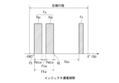
- the control of the fuel injection timing of the injector 20 is performed based on the crank angle (CA) detected by the crank angle sensor 102. Therefore, when calculating the main injection start timing FS, it is necessary to convert and set the crank angle. Regarding this, the procedure for calculating the main injection start timing FS while converting it into the crank angle will be described with reference to FIG. 6 as well.
- the horizontal axis represents the crank angle (CA)
- the preliminary injection Fp performed in the intake stroke is omitted
- the main injection Fm performed in the compression stroke and the pulse of the ignition control injection Fc are illustrated. Shows only.
- the fuel injection performed in the present embodiment is premised on performing the preliminary injection Fp, the main injection Fm, and the ignition control injection Fc, and the main injection Fm is the compression self-ignition near the compression top dead center.
- the target main injection end timing FE that is a predetermined time T0 before the injection start timing of the ignition control injection Fc that is performed at the timing.
- This predetermined time T0 is sufficiently mixed with the swirl flow S (see FIG. 5) of air introduced into the auxiliary combustion chamber 10 in the auxiliary combustion chamber 10 in addition to the above-described target injection interval FI. It is a time that is set considering the time for In this way, the target main injection end timing FE, which is traced back by the predetermined time T0 with respect to the injection start timing of the ignition control injection Fc, is set.
- the injection start timing of the ignition control injection Fc is defined based on the crank angle.
- a predetermined period T0 CA obtained by converting the predetermined time T0 per crank angle (CA) is obtained.
- the predetermined period T0 CA is a value that increases as the engine rotation speed Ne increases and decreases as the engine rotation speed decreases even if the predetermined time T0 is constant.
- the timing that is traced back by T0 CA from the injection start timing of the ignition control injection Fc is set as the target main injection end timing FE.
- the target main injection end timing FE it is not always necessary to use the injection start timing of the ignition control injection Fc as a reference, and the injection start timing of the ignition control injection Fc emission is narrow near the compression top dead center. If it changes only within the range, it may be determined based on the compression top dead center (0 °).
- the total main injection time FT is elapsed from the target main injection end timing FE so that the main injection Fm is completed at this target main injection end timing FE.
- the timing that goes back is calculated as the main injection start timing FS.
- the total main injection time FT is converted per crank angle (CA) in the same manner as the above-mentioned predetermined time T0, and the total main injection period FT is calculated. Calculate CA.
- the main injection start timing FS is determined by the crank angle.
- the target main injection end timing FE is set by the crank angle by the calculation means of the main injection start timing FS, and the target main injection end timing FE is set so that the main injection Fm is completed at the target main injection end timing FE.
- the timing that goes back by the main injection time FT is calculated as the main injection start timing FS. Therefore, the main injection start timing FS of the main injection Fm is advanced from the top dead center side to the bottom dead center side of the compression stroke as the engine rotation speed Ne changes from the low rotation speed to the high rotation speed. become.
- the first main injection Fm1 of the divided main injections Fm is started at the main injection start timing FS described above.
- the injection period of the first main injection Fm1 is obtained by converting the main injection time Fmt per time calculated by the above-described main injection time calculation means 125 into a crank angle 1 according to the engine rotation speed Ne. This is the main injection period Fmt CA per time.
- the target injection interval FI is opened until the injection of the second main injection Fm2 is started.
- the target injection interval FI calculates a target injection interval FI CA converted into the crank angle, by the target injection interval FI CA intervals
- the second main injection Fm2 is executed in the main injection period Fmt CA per time.
- the main injection Fm executed in this way is completed at the target main injection end timing FE, as shown in FIG.
- the ignition control injection Fc is executed to satisfy the ignition condition, and the premixed compression autoignition combustion with the ignition timing appropriately controlled is realized with high thermal efficiency.
- a glow plug 25 is provided in the auxiliary combustion chamber 10 of the diesel engine 1 according to this embodiment.
- the engine ECU 100 determines that the diesel engine 1 is in the low temperature start or is in the warm air mode after the low temperature start, based on the exhaust temperature detected by the exhaust temperature sensor 103 provided as the operating state detection means. , The engine speed Ne and the required load L, even when the operating state is to carry out the preliminary injection Fp, the preliminary injection Fp is not carried out and the glow plug 25 is operated to heat the auxiliary combustion chamber 10. To do. At this time, the fuel set as the preliminary injection Fp is added to the required main injection amount Qm of the main injection Fm.
- the preliminary injection Fp When it is determined that the temperature is low, only the preliminary injection Fp may be prohibited and the main injection Fm and the ignition control injection Fc may be performed. However, the premixed compression self-ignition combustion is stopped and the compression top dead center is reached. Normal diffusion combustion may be performed in which all fuel is injected near the point. This avoids the problem that the fuel injected in the auxiliary combustion chamber 10 does not evaporate sufficiently due to the low temperature of the diesel engine 1 and uniform premixing cannot be formed, and the unburned fuel contained in the exhaust gas is not burned. Prevents HC from increasing.
- the center axis C1 of the fuel spray F injected from the injector 20 and the hole center axis C2 of the communication hole 12 are offset.
- the fuel is mixed in the auxiliary combustion chamber 10 to a level sufficient for premixed compression ignition by the vortex flow S of the air flowing into the auxiliary combustion chamber 10 from the main combustion chamber 14 as the piston 5 rises.
- the EGR system 80 that recirculates the exhaust gas from the exhaust system 80 to the intake system 50 is arranged, and the exhaust gas can be supplied to the intake passage 52 according to the operating state.
- the emission of nitrogen oxides contained in the exhaust gas is reduced, and when the premixing is formed by the preliminary injection Fp and the main injection Fm and the compression ignition is performed near the compression top dead center, the EGR gas is also reduced. It is possible to control the ignition timing satisfactorily by, for example, preventing the premature ignition by turning on.
- the injection pressure of the fuel injected from the injector 20 is set within a range of 8 MPa to 40 MPa, and more preferably within a range of 15 MPa to 25 MPa.
- desired combustion performance can be obtained even in such an injection pressure range. That is, since the injection pressure can be set significantly lower than that of the direct injection type diesel engine of which the maximum injection pressure exceeds 200 MPa, it is not necessary to make the structure of the injector 20 itself excessively robust, and it is possible to electrically connect the fuel passage pipe 30 to A system for injecting fuel using the injector 20 that can be driven to a low temperature can be simply configured, and the manufacturing cost can be kept low.
Landscapes
- Engineering & Computer Science (AREA)
- Chemical & Material Sciences (AREA)
- Combustion & Propulsion (AREA)
- Mechanical Engineering (AREA)
- General Engineering & Computer Science (AREA)
- Signal Processing (AREA)
- Electrical Control Of Air Or Fuel Supplied To Internal-Combustion Engine (AREA)
- Combustion Methods Of Internal-Combustion Engines (AREA)
Priority Applications (2)
| Application Number | Priority Date | Filing Date | Title |
|---|---|---|---|
| US17/295,301 US20220003147A1 (en) | 2018-11-20 | 2019-10-24 | Subchamber diesel engine |
| EP19886081.9A EP3885565A4 (de) | 2018-11-20 | 2019-10-24 | Unterkammer-dieselmotor |
Applications Claiming Priority (2)
| Application Number | Priority Date | Filing Date | Title |
|---|---|---|---|
| JP2018217400A JP2020084848A (ja) | 2018-11-20 | 2018-11-20 | 副室式ディーゼル機関 |
| JP2018-217400 | 2018-11-20 |
Publications (1)
| Publication Number | Publication Date |
|---|---|
| WO2020105355A1 true WO2020105355A1 (ja) | 2020-05-28 |
Family
ID=70774049
Family Applications (1)
| Application Number | Title | Priority Date | Filing Date |
|---|---|---|---|
| PCT/JP2019/041623 Ceased WO2020105355A1 (ja) | 2018-11-20 | 2019-10-24 | 副室式ディーゼル機関 |
Country Status (4)
| Country | Link |
|---|---|
| US (1) | US20220003147A1 (de) |
| EP (1) | EP3885565A4 (de) |
| JP (1) | JP2020084848A (de) |
| WO (1) | WO2020105355A1 (de) |
Cited By (1)
| Publication number | Priority date | Publication date | Assignee | Title |
|---|---|---|---|---|
| CN114521525A (zh) * | 2022-03-09 | 2022-05-24 | 合肥师范学院 | 一种渔业使用的投饵机及投饵方法 |
Families Citing this family (3)
| Publication number | Priority date | Publication date | Assignee | Title |
|---|---|---|---|---|
| JP7445099B2 (ja) * | 2021-12-10 | 2024-03-07 | 株式会社クボタ | ディーゼルエンジン |
| CN117167133B (zh) * | 2023-10-17 | 2025-09-02 | 沈阳航空航天大学 | 一种压燃式发动机 |
| CN117345404B (zh) * | 2023-10-25 | 2025-06-20 | 天津大学 | 一种适用于氨柴大缸径发动机的燃烧系统及控制方法 |
Citations (11)
| Publication number | Priority date | Publication date | Assignee | Title |
|---|---|---|---|---|
| JPS5851232A (ja) * | 1981-09-22 | 1983-03-25 | Nissan Motor Co Ltd | デイ−ゼル機関の始動補助装置 |
| JPH03115723A (ja) * | 1989-09-29 | 1991-05-16 | Isuzu Motors Ltd | 副室式断熱エンジン |
| JPH0633816A (ja) * | 1992-07-10 | 1994-02-08 | Mazda Motor Corp | 副室式ディーゼルエンジンの燃料噴射装置 |
| JPH07116941A (ja) | 1993-10-26 | 1995-05-09 | Okuma Mach Works Ltd | 数値制御情報作成装置 |
| JPH09158730A (ja) * | 1995-12-08 | 1997-06-17 | Isuzu Ceramics Kenkyusho:Kk | 灯油や植物油を燃料とする遮熱形エンジン |
| JPH09217624A (ja) * | 1996-02-09 | 1997-08-19 | Isuzu Ceramics Kenkyusho:Kk | 重油を燃料とするディーゼルエンジン |
| JPH09317471A (ja) * | 1996-05-24 | 1997-12-09 | Isuzu Ceramics Kenkyusho:Kk | 低質燃料を用いたディーゼルエンジン |
| JP2000054904A (ja) * | 1998-08-11 | 2000-02-22 | Kubota Corp | ディーゼルエンジンの副室式燃焼室 |
| JP2000328974A (ja) * | 1999-05-17 | 2000-11-28 | Isuzu Ceramics Res Inst Co Ltd | Egr装置を備えたディーゼルエンジン |
| JP2000328973A (ja) * | 1999-05-17 | 2000-11-28 | Hideo Kawamura | Egr装置を備えたディーゼルエンジン |
| JP2001193526A (ja) * | 2000-01-12 | 2001-07-17 | Mazda Motor Corp | ターボ過給機付エンジンの制御装置 |
Family Cites Families (4)
| Publication number | Priority date | Publication date | Assignee | Title |
|---|---|---|---|---|
| JPH07116942B2 (ja) * | 1989-09-29 | 1995-12-18 | いすゞ自動車株式会社 | 副室式断熱エンジン及びその燃料噴射制御装置 |
| DE19639172C2 (de) * | 1996-09-24 | 2001-11-08 | Siemens Ag | Kraftstoff-Direkteinspritzverfahren für eine Dieselbrennkraftmaschine |
| DE102008020221B4 (de) * | 2008-04-22 | 2018-10-25 | Thomas Koch | Verfahren zum Starten einer selbstzündenden Brennkraftmaschine bei niedrigen Temperaturen |
| US9890689B2 (en) * | 2015-10-29 | 2018-02-13 | Woodward, Inc. | Gaseous fuel combustion |
-
2018
- 2018-11-20 JP JP2018217400A patent/JP2020084848A/ja active Pending
-
2019
- 2019-10-24 WO PCT/JP2019/041623 patent/WO2020105355A1/ja not_active Ceased
- 2019-10-24 US US17/295,301 patent/US20220003147A1/en not_active Abandoned
- 2019-10-24 EP EP19886081.9A patent/EP3885565A4/de not_active Withdrawn
Patent Citations (12)
| Publication number | Priority date | Publication date | Assignee | Title |
|---|---|---|---|---|
| JPS5851232A (ja) * | 1981-09-22 | 1983-03-25 | Nissan Motor Co Ltd | デイ−ゼル機関の始動補助装置 |
| JPH03115723A (ja) * | 1989-09-29 | 1991-05-16 | Isuzu Motors Ltd | 副室式断熱エンジン |
| JPH0633816A (ja) * | 1992-07-10 | 1994-02-08 | Mazda Motor Corp | 副室式ディーゼルエンジンの燃料噴射装置 |
| JPH07116941A (ja) | 1993-10-26 | 1995-05-09 | Okuma Mach Works Ltd | 数値制御情報作成装置 |
| JPH09158730A (ja) * | 1995-12-08 | 1997-06-17 | Isuzu Ceramics Kenkyusho:Kk | 灯油や植物油を燃料とする遮熱形エンジン |
| JPH09217624A (ja) * | 1996-02-09 | 1997-08-19 | Isuzu Ceramics Kenkyusho:Kk | 重油を燃料とするディーゼルエンジン |
| JPH09317471A (ja) * | 1996-05-24 | 1997-12-09 | Isuzu Ceramics Kenkyusho:Kk | 低質燃料を用いたディーゼルエンジン |
| JP2000054904A (ja) * | 1998-08-11 | 2000-02-22 | Kubota Corp | ディーゼルエンジンの副室式燃焼室 |
| JP3851727B2 (ja) | 1998-08-11 | 2006-11-29 | 株式会社クボタ | ディーゼルエンジンの副室式燃焼室 |
| JP2000328974A (ja) * | 1999-05-17 | 2000-11-28 | Isuzu Ceramics Res Inst Co Ltd | Egr装置を備えたディーゼルエンジン |
| JP2000328973A (ja) * | 1999-05-17 | 2000-11-28 | Hideo Kawamura | Egr装置を備えたディーゼルエンジン |
| JP2001193526A (ja) * | 2000-01-12 | 2001-07-17 | Mazda Motor Corp | ターボ過給機付エンジンの制御装置 |
Non-Patent Citations (1)
| Title |
|---|
| See also references of EP3885565A4 |
Cited By (1)
| Publication number | Priority date | Publication date | Assignee | Title |
|---|---|---|---|---|
| CN114521525A (zh) * | 2022-03-09 | 2022-05-24 | 合肥师范学院 | 一种渔业使用的投饵机及投饵方法 |
Also Published As
| Publication number | Publication date |
|---|---|
| JP2020084848A (ja) | 2020-06-04 |
| US20220003147A1 (en) | 2022-01-06 |
| EP3885565A1 (de) | 2021-09-29 |
| EP3885565A4 (de) | 2022-08-10 |
Similar Documents
| Publication | Publication Date | Title |
|---|---|---|
| CN100564828C (zh) | 内燃机 | |
| KR101693895B1 (ko) | 복합 착화방식의 디젤-가솔린 혼합연소엔진과 그 제어방법 및 복합 착화방식의 디젤-가솔린 혼합연소시스템 | |
| US8037864B2 (en) | Diesel engine | |
| JP7663263B2 (ja) | 温度制御可能なグロープラグの補助する圧縮点火メタノールエンジン及びその制御方法 | |
| WO2020105355A1 (ja) | 副室式ディーゼル機関 | |
| CN101142399B (zh) | 用于内燃机的燃料供应设备 | |
| JP2009167821A (ja) | 内燃機関の燃料噴射制御装置 | |
| KR20130068429A (ko) | 복합 착화방식의 디젤-가솔린 혼합연소엔진과 그 제어방법 및 복합 착화방식의 디젤-가솔린 혼합연소시스템 | |
| US7252069B2 (en) | Gas fuel engine and control method for the same | |
| US20130192561A1 (en) | Ignition delay period estimation apparatus and ignition time control apparatus for internal combustion engine | |
| WO2011118031A1 (ja) | 内燃機関の燃焼制御装置 | |
| EP2392808A1 (de) | Steuerungsvorrichtung für einen verbrennungsmotor | |
| CN101939524B (zh) | 内燃机的燃料喷射控制装置 | |
| CN118742725A (zh) | 氢气对置活塞发动机 | |
| JP6508186B2 (ja) | 内燃機関の制御装置 | |
| CN118911822A (zh) | 一种基于vnt的氨气柴油双燃料发动机的可变进气系统及其控制方法 | |
| JP5196072B1 (ja) | 内燃機関の制御装置 | |
| WO2010035342A1 (ja) | 内燃機関の燃料噴射制御装置 | |
| JP5866813B2 (ja) | 内燃機関 | |
| JP2007154853A (ja) | 火花点火式直噴内燃機関の制御装置 | |
| JP5093407B2 (ja) | 内燃機関の燃焼制御装置 | |
| JP5257520B2 (ja) | 内燃機関の制御装置 | |
| KR20180034495A (ko) | 분사 온도를 통한 반응도 제어로 압축착화 내부 연소 엔진의 연소를 제어하는 방법 | |
| JP2021055662A (ja) | 燃料改質エンジン | |
| WO2020105350A1 (ja) | 副室式ディーゼル機関 |
Legal Events
| Date | Code | Title | Description |
|---|---|---|---|
| 121 | Ep: the epo has been informed by wipo that ep was designated in this application |
Ref document number: 19886081 Country of ref document: EP Kind code of ref document: A1 |
|
| NENP | Non-entry into the national phase |
Ref country code: DE |
|
| ENP | Entry into the national phase |
Ref document number: 2019886081 Country of ref document: EP Effective date: 20210621 |