WO2020105943A1 - Cigarette et dispositif de génération d'aérosol pour cigarette - Google Patents
Cigarette et dispositif de génération d'aérosol pour cigaretteInfo
- Publication number
- WO2020105943A1 WO2020105943A1 PCT/KR2019/015420 KR2019015420W WO2020105943A1 WO 2020105943 A1 WO2020105943 A1 WO 2020105943A1 KR 2019015420 W KR2019015420 W KR 2019015420W WO 2020105943 A1 WO2020105943 A1 WO 2020105943A1
- Authority
- WO
- WIPO (PCT)
- Prior art keywords
- cigarette
- aerosol
- electromagnetic derivative
- wrapper
- rod
- Prior art date
- Legal status (The legal status is an assumption and is not a legal conclusion. Google has not performed a legal analysis and makes no representation as to the accuracy of the status listed.)
- Ceased
Links
Images




Classifications
-
- A—HUMAN NECESSITIES
- A24—TOBACCO; CIGARS; CIGARETTES; SIMULATED SMOKING DEVICES; SMOKERS' REQUISITES
- A24D—CIGARS; CIGARETTES; TOBACCO SMOKE FILTERS; MOUTHPIECES OF CIGARS OR CIGARETTES; MANUFACTURE OF TOBACCO SMOKE FILTERS OR MOUTHPIECES
- A24D1/00—Cigars; Cigarettes
- A24D1/20—Cigarettes specially adapted for simulated smoking devices
-
- A—HUMAN NECESSITIES
- A24—TOBACCO; CIGARS; CIGARETTES; SIMULATED SMOKING DEVICES; SMOKERS' REQUISITES
- A24D—CIGARS; CIGARETTES; TOBACCO SMOKE FILTERS; MOUTHPIECES OF CIGARS OR CIGARETTES; MANUFACTURE OF TOBACCO SMOKE FILTERS OR MOUTHPIECES
- A24D1/00—Cigars; Cigarettes
- A24D1/02—Cigars; Cigarettes with special covers
-
- A—HUMAN NECESSITIES
- A24—TOBACCO; CIGARS; CIGARETTES; SIMULATED SMOKING DEVICES; SMOKERS' REQUISITES
- A24D—CIGARS; CIGARETTES; TOBACCO SMOKE FILTERS; MOUTHPIECES OF CIGARS OR CIGARETTES; MANUFACTURE OF TOBACCO SMOKE FILTERS OR MOUTHPIECES
- A24D1/00—Cigars; Cigarettes
- A24D1/04—Cigars; Cigarettes with mouthpieces or filter-tips
- A24D1/045—Cigars; Cigarettes with mouthpieces or filter-tips with smoke filter means
-
- A—HUMAN NECESSITIES
- A24—TOBACCO; CIGARS; CIGARETTES; SIMULATED SMOKING DEVICES; SMOKERS' REQUISITES
- A24D—CIGARS; CIGARETTES; TOBACCO SMOKE FILTERS; MOUTHPIECES OF CIGARS OR CIGARETTES; MANUFACTURE OF TOBACCO SMOKE FILTERS OR MOUTHPIECES
- A24D1/00—Cigars; Cigarettes
- A24D1/08—Cigars; Cigarettes with lighting means
-
- A—HUMAN NECESSITIES
- A24—TOBACCO; CIGARS; CIGARETTES; SIMULATED SMOKING DEVICES; SMOKERS' REQUISITES
- A24F—SMOKERS' REQUISITES; MATCH BOXES; SIMULATED SMOKING DEVICES
- A24F40/00—Electrically operated smoking devices; Component parts thereof; Manufacture thereof; Maintenance or testing thereof; Charging means specially adapted therefor
- A24F40/10—Devices using liquid inhalable precursors
-
- A—HUMAN NECESSITIES
- A24—TOBACCO; CIGARS; CIGARETTES; SIMULATED SMOKING DEVICES; SMOKERS' REQUISITES
- A24F—SMOKERS' REQUISITES; MATCH BOXES; SIMULATED SMOKING DEVICES
- A24F40/00—Electrically operated smoking devices; Component parts thereof; Manufacture thereof; Maintenance or testing thereof; Charging means specially adapted therefor
- A24F40/40—Constructional details, e.g. connection of cartridges and battery parts
- A24F40/46—Shape or structure of electric heating means
- A24F40/465—Shape or structure of electric heating means specially adapted for induction heating
-
- A—HUMAN NECESSITIES
- A24—TOBACCO; CIGARS; CIGARETTES; SIMULATED SMOKING DEVICES; SMOKERS' REQUISITES
- A24F—SMOKERS' REQUISITES; MATCH BOXES; SIMULATED SMOKING DEVICES
- A24F40/00—Electrically operated smoking devices; Component parts thereof; Manufacture thereof; Maintenance or testing thereof; Charging means specially adapted therefor
- A24F40/50—Control or monitoring
-
- A—HUMAN NECESSITIES
- A24—TOBACCO; CIGARS; CIGARETTES; SIMULATED SMOKING DEVICES; SMOKERS' REQUISITES
- A24F—SMOKERS' REQUISITES; MATCH BOXES; SIMULATED SMOKING DEVICES
- A24F40/00—Electrically operated smoking devices; Component parts thereof; Manufacture thereof; Maintenance or testing thereof; Charging means specially adapted therefor
- A24F40/50—Control or monitoring
- A24F40/51—Arrangement of sensors
-
- A—HUMAN NECESSITIES
- A24—TOBACCO; CIGARS; CIGARETTES; SIMULATED SMOKING DEVICES; SMOKERS' REQUISITES
- A24F—SMOKERS' REQUISITES; MATCH BOXES; SIMULATED SMOKING DEVICES
- A24F40/00—Electrically operated smoking devices; Component parts thereof; Manufacture thereof; Maintenance or testing thereof; Charging means specially adapted therefor
- A24F40/50—Control or monitoring
- A24F40/53—Monitoring, e.g. fault detection
-
- D—TEXTILES; PAPER
- D21—PAPER-MAKING; PRODUCTION OF CELLULOSE
- D21H—PULP COMPOSITIONS; PREPARATION THEREOF NOT COVERED BY SUBCLASSES D21C OR D21D; IMPREGNATING OR COATING OF PAPER; TREATMENT OF FINISHED PAPER NOT COVERED BY CLASS B31 OR SUBCLASS D21G; PAPER NOT OTHERWISE PROVIDED FOR
- D21H17/00—Non-fibrous material added to the pulp, characterised by its constitution; Paper-impregnating material characterised by its constitution
- D21H17/63—Inorganic compounds
-
- D—TEXTILES; PAPER
- D21—PAPER-MAKING; PRODUCTION OF CELLULOSE
- D21H—PULP COMPOSITIONS; PREPARATION THEREOF NOT COVERED BY SUBCLASSES D21C OR D21D; IMPREGNATING OR COATING OF PAPER; TREATMENT OF FINISHED PAPER NOT COVERED BY CLASS B31 OR SUBCLASS D21G; PAPER NOT OTHERWISE PROVIDED FOR
- D21H19/00—Coated paper; Coating material
- D21H19/02—Metal coatings
-
- D—TEXTILES; PAPER
- D21—PAPER-MAKING; PRODUCTION OF CELLULOSE
- D21H—PULP COMPOSITIONS; PREPARATION THEREOF NOT COVERED BY SUBCLASSES D21C OR D21D; IMPREGNATING OR COATING OF PAPER; TREATMENT OF FINISHED PAPER NOT COVERED BY CLASS B31 OR SUBCLASS D21G; PAPER NOT OTHERWISE PROVIDED FOR
- D21H27/00—Special paper not otherwise provided for, e.g. made by multi-step processes
-
- H—ELECTRICITY
- H05—ELECTRIC TECHNIQUES NOT OTHERWISE PROVIDED FOR
- H05B—ELECTRIC HEATING; ELECTRIC LIGHT SOURCES NOT OTHERWISE PROVIDED FOR; CIRCUIT ARRANGEMENTS FOR ELECTRIC LIGHT SOURCES, IN GENERAL
- H05B6/00—Heating by electric, magnetic or electromagnetic fields
- H05B6/02—Induction heating
- H05B6/36—Coil arrangements
- H05B6/365—Coil arrangements using supplementary conductive or ferromagnetic pieces
-
- A—HUMAN NECESSITIES
- A24—TOBACCO; CIGARS; CIGARETTES; SIMULATED SMOKING DEVICES; SMOKERS' REQUISITES
- A24F—SMOKERS' REQUISITES; MATCH BOXES; SIMULATED SMOKING DEVICES
- A24F40/00—Electrically operated smoking devices; Component parts thereof; Manufacture thereof; Maintenance or testing thereof; Charging means specially adapted therefor
- A24F40/20—Devices using solid inhalable precursors
Definitions
- the invention disclosed by this application relates to a cigarette and an aerosol generating device for cigarettes.
- the aerosol-generating device has a safety risk, such as heating the heater in a state in which a cigarette is not inserted due to inexperienced operation or carelessness of the user, causing burns to the user's skin. Accordingly, there is a demand for a method for promoting user safety by heating the cigarette only when a cigarette suitable for the aerosol-generating device is inserted.
- An object of the present invention is to provide an aerosol generating device that detects that a cigarette is inserted and a cigarette that is inserted into the aerosol generating device by using electromagnetic induction.
- the cigarette may include a tobacco rod, a shear plug adjacent the front end of the cigarette rod, a filter rod adjacent the rear end of the cigarette rod, and an electromagnetic derivative located in the shear plug.
- the electromagnetic derivative may be a thin film surrounding at least a portion of the shear plug.
- the cigarette further includes a wrapper surrounding the shear plug, and the electromagnetic derivative may be a thin film, one side of which overlaps the inner surface of the wrapper.
- the cigarette may include a first wrapper surrounding the shear plug and a fifth wrapper surrounding the first wrapper, and the electromagnetic derivative may be a thin film positioned between the first wrapper and the fifth wrapper.
- the electromagnetic derivative may include at least one of conductive metal, magnetic ink, and magnetic tape.
- the electromagnetic derivative may include at least one of aluminum (Al) and graphite (Graphite).
- the electromagnetic derivative may have a length of 6 mm or more and less than 9 mm in the longitudinal direction of the cigarette.
- the electromagnetic derivative may be a metal thin film having a thickness of 6 ⁇ m or more and less than 7 ⁇ m.
- the tobacco rod upon insertion into the aerosol-generating device, the tobacco rod is surrounded by a heating unit capable of heating the tobacco rod, and the shear plug can be positioned proximate to a sensor comprising a coil capable of sensing electromagnetic derivatives.
- the aerosol-generating device includes a case, a cigarette rod, a filter rod, a heating plug and a coil for heating a cigarette including an electromagnetic derivative located in the plug and a shear plug adjacent to the front end of the cigarette rod, and the cigarette
- the detector and heater controls the operation of the detector and heater that detects the change in the characteristic of the current flowing through the coil caused by the electromagnetic induction action with the electromagnetic derivative, and inserts the cigarette based on the change in the characteristic of the current detected by the detector
- the aerosol-generating device may further include a vaporizer that vaporizes the liquid composition to generate an aerosol, and delivers the aerosol into the cigarette through a shear plug.
- user safety can be secured by operating the heating unit while the cigarette is inserted.
- FIG. 1 is a perspective view of an embodiment of a cigarette.
- FIG. 2 is a perspective view of another embodiment of a cigarette.
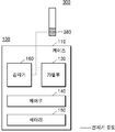
- 3 and 4 are block diagrams showing embodiments of the aerosol-generating device.
- FIG. 5 is a view of an aerosol generating device in a state in which a cigarette is inserted.
- FIG. 6 is a graph of the current characteristics that the aerosol generating device senses according to the state of insertion of the cigarette.
- the cigarette may include a tobacco rod, a shear plug adjacent the front end of the cigarette rod, a filter rod adjacent the rear end of the cigarette rod, and an electromagnetic derivative located in the shear plug.
- the aerosol-generating device includes a case, a cigarette rod, a filter rod, a heating plug and a coil for heating a cigarette including an electromagnetic derivative located in the plug and a shear plug adjacent to the front end of the cigarette rod, and the cigarette
- the detector and heater controls the operation of the detector and heater that detects the change in the characteristic of the current flowing through the coil caused by the electromagnetic induction action with the electromagnetic derivative, and inserts the cigarette based on the change in the characteristic of the current detected by the detector It may include a control unit for determining.
- ⁇ unit and “ ⁇ module” described in the specification mean a unit that processes at least one function or operation, which may be implemented in hardware or software, or a combination of hardware and software.
- the aerosol-generating device may be a device that generates an aerosol using an aerosol-generating material to generate an aerosol that can be directly inhaled into the user's lungs through the user's mouth.
- the aerosol-generating device may be a holder.
- the term "puff" refers to the inhalation of the user, and inhalation may refer to a situation in which the user's mouth or nose pulls into the user's mouth, nasal cavity, or lungs.
- FIG. 1 is a perspective view of an embodiment of a cigarette.
- a cigarette 300 may include a cigarette rod 31 and a filter rod 32 and a shear plug 33, and may include an electromagnetic derivative 380. .
- the tobacco rod 31 includes tobacco material and aerosol-generating material.
- the tobacco material may be tobacco.
- the filter rod 32 may cool the aerosol or filter certain components contained within the aerosol.
- the front end plug 33 may be located on one side of the tobacco rod 31 opposite the filter rod 32.
- the front end plug 33 can prevent the cigarette rod 31 from escaping to the outside, and the aerosol liquefied from the cigarette rod 31 flows into the aerosol-generating device (1 in FIGS. 1 to 3) during smoking. Can be prevented.
- the cigarette 300 may be packaged by at least one wrapper 35.
- Cigarette 300 may include an electromagnetic derivative (380).
- the electromagnetic derivative 380 may be sensed through the sensor 160 of the aerosol-generating device 100 by electromagnetic induction.
- the electromagnetic derivative 380 may include a conductor capable of inducing eddy current and a magnetic body capable of generating a change in magnetic flux.
- the electromagnetic derivative 380 may include a conductive metal material, magnetic ink, magnetic tape, or the like.
- the electromagnetic derivative 380 may be aluminum (Al) foil or graphite (Graphite).
- the electromagnetic derivative 380 may include, without limitation, substances that can be sensed by causing a change in magnetic flux in the coil of the sensor 160.
- the position in which the electromagnetic derivative 380 is provided in the cigarette 300 may vary.
- the electromagnetic derivative 380 may be disposed in an area corresponding to the shear plug 33.
- the electromagnetic derivative 380 immediately starts when the cigarette 300 is inserted. It may be inserted into the aerosol generating device 100.
- the sensor 160 may detect the insertion of the cigarette 300 at an early point in time by detecting the approach of the electromagnetic derivative 380.
- the detector 160 detects the separation of the electromagnetic derivative 380, so that the cigarette 300 is completely You can detect that you have strayed.
- the electromagnetic derivative 380 may be, for example, a metal foil.
- the electromagnetic derivative 380 may wrap all or part of the contents of the cigarette 300 along the periphery of the cigarette 300.
- the electromagnetic derivative 380 may be surrounded by the wrapper 35 while one surface of the metal foil is overlapped while facing the inner surface of the wrapper 35.
- the length of the electromagnetic derivative 380 extending in the axial direction of the cigarette 300 may be 6 mm to 9 mm. Specifically, the axial length of the cigarette 300 of the electromagnetic derivative 380 may be 7 mm.
- the electromagnetic derivative 380 may be, for example, aluminum (Al) foil, and the thickness may be 6 ⁇ m to 7 ⁇ m. Specifically, the thickness may be 6.3 ⁇ m.
- the diameter of the cigarette 300 is within the range of 5 mm to 9 mm, and the length may be about 48 mm, but is not limited thereto.
- the length of the front end plug 33 is about 7 mm
- the length of the cigarette rod 31 is about 15 mm
- the length of the first segment 321 is about 12 mm
- the length of the second segment 322 is about 14 mm.
- the aerosol-generating material may include at least one of glycerin, propylene glycol, ethylene glycol, dipropylene glycol, diethylene glycol, triethylene glycol, tetraethylene glycol and oleyl alcohol, It is not limited to this.
- the tobacco rod 31 may contain other additives, such as flavoring agents, wetting agents and / or organic acids.
- a flavoring solution such as menthol or moisturizer may be added to the tobacco rod 31 by spraying it onto the tobacco rod 31.
- the cigarette rod 31 may be manufactured in various ways.
- the tobacco rod 31 may be made of a sheet or may be made of strands.
- the tobacco rod 31 may be made of cut tobacco cut into cut grass.
- the tobacco rod 31 may be surrounded by a heat-conducting material.
- the heat conducting material can be a cellulose acetate filter.
- the shape of the filter rod 32 is not limited.
- the filter rod 32 may be a cylindrical type rod or a tube type rod including a hollow inside.
- the filter rod 32 may be a recessed type rod. If the filter rod 32 is composed of a plurality of segments, at least one of the segments may be manufactured in a different shape.
- the shear plug 33 can be made of cellulose acetate.
- the front end plug 33 may include at least one channel, and the cross-sectional shape of the channel may be manufactured in various ways.
- FIG. 2 is a perspective view of another embodiment of a cigarette.
- the filter rod 32 may be composed of a single segment or a plurality of segments.
- the filter rod 32 may include a first segment 321 that cools the aerosol and a second segment 322 that filters certain components contained in the aerosol.
- the first segment 321 of the filter rod 32 may cool the aerosol generated by the heating unit 130 heating the cigarette rod 31. Therefore, the user can inhale the aerosol cooled to a suitable temperature.
- the length or diameter of the first segment 321 may be variously determined according to the shape of the cigarette 300.
- the length of the first segment 321 may be suitably employed within a range of 7 mm to 20 mm.
- the length of the first segment 321 may be about 12 mm or 14 mm, but is not limited thereto.
- the first segment 321 of the filter rod 32 may be a cellulose acetate filter.
- the first segment 321 may be manufactured by inserting a structure such as a film or tube of the same or different material inside (eg, hollow).
- the first segment 321 may be a tube-shaped structure including a hollow inside.
- the heating unit 130 is inserted by the first segment 321
- the internal material of the cigarette rod 31 may be prevented from being pushed back, and a cooling effect of the aerosol may also be generated.
- the diameter of the hollow included in the first segment 321 may be an appropriate diameter within the range of 2mm to 4.5mm, but is not limited thereto.
- the first segment 321 may be manufactured by weaving a polymer fiber.
- a flavoring liquid may be applied to fibers made of a polymer.
- the first segment 321 may be manufactured by weaving together fibers made of a polymer and separate fibers coated with a flavoring solution.
- the first segment 321 may be formed by a crimped polymer sheet. Thereby, the surface area in contact with the aerosol can be increased. Therefore, the aerosol cooling effect of the cooling structure 830 can be further improved.
- the polymer is selected from the group consisting of polyethylene (PE), polypropylene (PP), polyvinyl chloride (PVC), polyethylene terephthalate (PET), polylactic acid (PLA), cellulose acetate (CA) and aluminum foil. It can be made of materials.
- the first segment 321 may include singular or plural channels extending in the longitudinal direction.
- a channel means a passage through which a gas (eg, air or aerosol) passes.
- a thread containing a volatile flavor component may be included in the first segment 321.
- the volatile flavor component may be menthol, but is not limited thereto.
- the second segment 322 of the filter rod 32 may be a cellulose acetate filter.
- the length of the second segment 322 can be suitably employed within a range of 4 mm to 20 mm.
- the length of the second segment 322 may be about 14 mm or about 12 mm, but is not limited thereto.
- the second segment 322 may be made of cellulose acetate.
- the flavor may be produced by spraying a fragrance liquid to the second segment 322.
- a separate fiber coated with a fragrance liquid may be inserted into the second segment 322.
- the aerosol generated in the tobacco rod 31 is cooled as it passes through the first segment 321, and the cooled aerosol is delivered to the user through the second segment 322. Accordingly, when a flavoring element is added to the second segment 322, an effect of enhancing the persistence of flavor delivered to the user may be generated.
- the wrapper 35 may include a plurality of wrappers surrounding each segment.
- the front end plug 33 is packaged by the first wrapper 351
- the cigarette rod 31 is packaged by the second wrapper 352
- the first segment (by the third wrapper 353) 321) is packaged
- the second segment 322 may be packaged by the fourth wrapper 354.
- the entire cigarette 300 may be repackaged by the fifth wrapper 355.
- the first wrapper 351 may be a metal foil such as aluminum foil combined with a general filter wrapper.
- the second wrapper 352 and the third wrapper 353 may be made of a general filter wrapper.
- the second wrapper 352 and the third wrapper 353 may be porous wrapper or non-porous wrapper.
- At least one perforation 36 may be formed in the wrapper 35. Air outside the cigarette 300 may be introduced into the cigarette 300 through the perforation 36 formed in the wrapper 35.
- the number of perforations 36 may vary from 3 to 10, etc., and the separation distance between each perforation 36 may be constant, or may be formed according to different separation distances with a constant pattern.
- the electromagnetic derivative 380 may be surrounded by the first wrapper 351 while one surface of the metal foil is overlapped while facing the inner surface of the first wrapper 351. According to another embodiment, the metal foil of the electromagnetic derivative 380 may surround the cigarette 300 while being superimposed between the first wrapper 351 and the fifth wrapper 355. As a result, the electromagnetic derivative 380 can be prevented from being damaged by foreign materials by the wrapper 35.
- the electromagnetic derivative 380 may have one end contacting the first wrapper 351 surrounding the shear plug 33 and the other end contacting the second wrapper 352 surrounding the cigarette rod 31. Alternatively, the other end may reach the third wrapper 353 surrounding the filter rod 32.
- 3 and 4 are block diagrams showing embodiments of the aerosol-generating device.
- the aerosol-generating device 100 may include a case 110, a heating unit 130, a sensor 160, a battery 150, and a control unit 140.
- the cigarette 300 may be provided with an electromagnetic derivative (380). The cigarette 300 may be inserted into the interior space of the aerosol-generating device 100.
- FIGS. 3 to 4 components related to the present embodiment are illustrated. Accordingly, those of ordinary skill in the art related to this embodiment may understand that other general-purpose components in addition to the components shown in FIGS. 1 to 2 may be further included in the aerosol-generating device 100. .
- FIG. 3 shows that the battery 150, the control unit 140, and the heating unit 130 are shown as being arranged in a line.
- FIG. 3 shows that the battery 150, the control unit 140, the vaporizer 170, and the heating unit 130 are arranged in a line.
- FIG. 4 shows that the vaporizer 170 and the heating unit 130 are arranged in parallel.
- the internal structure of the aerosol-generating device 100 is not limited to that shown in FIGS. 3 to 4. In other words, according to the design of the aerosol-generating device 100, the arrangement of the battery 150, the control unit 140, the heating unit 130, and the vaporizer 170 may be changed.
- the aerosol-generating device 100 may generate an aerosol by operating the heating unit 130 and / or the vaporizer 170.
- the aerosol generated by the heating unit 130 and / or the vaporizer 170 passes through the cigarette 300 and is delivered to the user.
- the aerosol-generating device 100 may heat the heating unit 130.
- the case 110 forms a part of the exterior of the aerosol-generating device 100 and functions to receive and protect various components therein.
- the heating unit 130 is heated by the electric power supplied from the battery 150, thereby heating and vaporizing the aerosol-generating material.
- the heating unit 130 may be applied without limitation as long as it can be heated to a desired temperature for vaporizing the aerosol.
- the desired temperature may be preset in the aerosol-generating device 100, or may be set to a desired temperature by the user.
- the heating unit 130 may be located inside or outside the cigarette 300 to heat the aerosol-generating material.
- the heating unit 130 may be an electric resistive heater.
- the heating unit 130 may include an electrically conductive track, and as the current flows through the electrically conductive track, the heating unit 130 may be heated.
- the heating unit 130 may be an induction heating heater.
- the heating unit 130 may include an electrically conductive coil 260 for heating the aerosol-generating material in an induction heating method, and the cigarette 300 or the liquid cartridge may be heated by an induction heating heater. It may include a acceptor 320.
- the shape of the heating unit 130 may be manufactured in various shapes.
- the heating unit 130 may include a tubular heating element, a plate-shaped heating element, a needle-shaped heating element, or a rod-shaped heating element.
- the heating unit 130 may heat the inside or outside of the cigarette 300 according to the shape of the heating element.
- heating unit 130 Although only one heating unit 130 is illustrated in FIGS. 3 and 4, the present invention is not limited thereto, and a plurality of heating units 130 may be disposed in the aerosol generating device 100.
- the plurality of heating units 130 may be disposed to be inserted into the cigarette 300, or may be disposed outside the cigarette 300.
- some of the plurality of heating units 130 may be disposed to be inserted into the cigarette 300, and the rest may be disposed outside the cigarette 300.
- the detector 160 may detect the state of insertion into the aerosol generating device 100 of the cigarette 300.
- the detector 160 may include a coil. As the cigarette 300 is inserted into or separated from the case 110, electromagnetic induction may occur between the coil and the electromagnetic derivative 380. At this time, the detector 160 may detect a characteristic change of the current flowing through the coil generated by electromagnetic induction.
- detector 160 Although only one detector 160 is illustrated in FIGS. 3 and 4, according to an embodiment, two or more detectors 160 may be disposed.
- the detectors 160 can detect the state of insertion of the cigarette 300 at different locations.
- the plurality of detectors 160 may be spaced apart in the vertical direction.
- Eddy current may be induced and flow through the electromagnetic derivative 380 by the sensor 160.
- the detector 160 may detect the eddy current induced in the coil of the detector 160 again by the electromagnetic derivative 380.
- the current characteristics at which the sensor 160 detects the change using electromagnetic induction may vary.
- current characteristics include current value of a current flowing through a coil, frequency value in the case of alternating current, magnitude of a voltage, inductance value of a coil whose current is changed by mutual induction, quality factor of a coil, effective resistance and impedance value, etc. You can.
- the detector 160 including the detector 160 may further include a frequency measuring element, a rectifier, an amplifier, an oscillation circuit that generates electrical vibration, and the like.
- the method in which the sensor 160 detects a change in characteristics of a current flowing through a coil due to electromagnetic induction may be various.
- an alternating current may be applied to the coil, and the alternating current may induce an eddy current in the electromagnetic derivative 380.
- the eddy current flowing through the electromagnetic derivative 380 may induce a change in the current flowing through the coil again through mutual induction with the coil.
- the detector 160 including the detector 160 may detect a change in current flowing through the coil.
- the detector 160 may include a transmitting coil through which an alternating current flows, and induces an eddy current in the electromagnetic derivative 380 and a sensing coil that senses an eddy current flowing in the electromagnetic derivative 380.
- the transmitting coil and the sensing coil are arranged in a vertical direction, so that interference between the transmitting coil and the sensing coil can be minimized.
- the method in which the detector 160 detects a mutual induction phenomenon occurring between the coil and the electromagnetic derivative 380 may be various, and is not limited to the above-described example.
- the detection of the characteristic change of the current by the electromagnetic induction of the sensor 160 may include not only measuring the current directly using an ammeter, but also detecting the current in an indirect method.
- detecting the change in current by measuring the induced electromotive force induced in the coil in the form of a voltage may also be included in the sensor 160 detecting the change in current.
- the aerosol-generating device may further include a vaporizer.
- the vaporizer 170 may generate an aerosol by heating the liquid composition, and the generated aerosol may be delivered to the user through the cigarette 300.
- the aerosol generated by the vaporizer 170 may move along the airflow passage of the aerosol-generating device 100, and the aerosol generated by the vaporizer 170 passes through the cigarette 300 It can be configured to be delivered to the user.
- the vaporizer 170 may heat the liquid composition to generate an aerosol, and discharge the aerosol toward the cigarette 300 so that the aerosol passes through the cigarette 300 inserted into the cigarette insert.
- vaporizer 170 may include, but is not limited to, a liquid reservoir, a liquid delivery means, and a heating element.
- the liquid reservoir, liquid delivery means and heating elements may be included in the aerosol-generating device 100 as independent modules.
- the liquid storage unit may store a liquid composition.
- the liquid composition may be a liquid containing a tobacco-containing substance containing a volatile tobacco flavor component, or may be a liquid containing a non-tobacco substance.
- the liquid storage unit may be manufactured to be detachable from the vaporizer 170, or may be manufactured integrally with the vaporizer 170.
- the liquid composition may include water, solvent, ethanol, plant extracts, flavoring agents, flavoring agents, or vitamin mixtures.
- the fragrance may include menthol, peppermint, spearmint oil, various fruit flavor ingredients, and the like, but is not limited thereto.
- Flavoring agents may include ingredients that can provide a variety of flavors or flavors to the user.
- the vitamin mixture may be a mixture of at least one of vitamin A, vitamin B, vitamin C, and vitamin E, but is not limited thereto.
- the liquid composition may include aerosol formers such as glycerin and propylene glycol.
- the liquid delivery means can deliver the liquid composition of the liquid reservoir to the heating element.
- the liquid delivery means may be a wick such as cotton fiber, ceramic fiber, glass fiber, or porous ceramic, but is not limited thereto.
- the heating element is an element for heating the liquid composition delivered by the liquid delivery means.
- the heating element may be a metal heating wire, a metal heating plate, or a ceramic heater, but is not limited thereto.
- the heating element may be composed of a conductive filament such as a nichrome wire, and may be arranged in a structure wound around the liquid delivery means. The heating element can be heated by a current supply and can transfer heat to the liquid composition in contact with the heating element, thereby heating the liquid composition. As a result, aerosols can be produced.
- the vaporizer 170 may be referred to as a cartomizer or an atomizer, but is not limited thereto.
- the battery 150 supplies power used to operate the aerosol-generating device 100.
- the battery 150 may supply power so that the heating unit 130 can be heated, and may supply power necessary for the control unit 140 to operate.
- the battery 150 may supply power so that the detector 160 can operate.
- the battery 150 may supply power required for the display, sensor, motor, and the like installed in the aerosol generating device 100 to operate.
- the battery 150 may be electrically connected to the adapter, and the DC output from the battery 150 may be converted into an AC current and output to the adapter.
- the control unit 140 controls the overall operation of the aerosol-generating device 100. Specifically, the control unit 140 controls the operation of the battery 150, the heating unit 130, and the sensor 160, as well as other components included in the aerosol generating device 100.
- the control unit 140 may control the operation of the detector 160.
- the control unit 140 may differently adjust the frequency of the alternating current applied to the detector 160, the magnitude of the current, and the like.
- the controller 140 may determine whether the electromagnetic derivative 380 is approaching the coil based on the current change flowing through the coil sensed by the sensor 160. In other words, the control unit 140 may determine whether the cover 120 including the electromagnetic derivative 380 is coupled to the case 110 or separated.
- the control unit 140 includes at least one processor.
- the processor may be implemented as an array of multiple logic gates, or a combination of a general-purpose microprocessor and a memory in which programs executable on the microprocessor are stored.
- programs executable on the microprocessor are stored.
- those skilled in the art to which this embodiment belongs may understand that it may be implemented with other types of hardware.
- the aerosol-generating device 100 may further include general-purpose components in addition to the battery 150, the heating unit 130, the sensor 160, and the control unit 140.
- the aerosol generating apparatus 100 may include a display capable of outputting visual information and / or a motor for outputting tactile information, a charging terminal for charging the battery 150, and the like.
- the motor may inform, for example, that the heating of the heating unit 130 is completed through vibration.
- the aerosol-generating device 100 includes an LED, and may display an operating state of the heating unit 130 through the LED.
- the aerosol-generating device 100 may constitute a system together with a separate cradle (not shown).
- the cradle may be used to charge the battery 150 of the aerosol-generating device 100.
- the heating unit 130 may be heated while the cradle and the aerosol-generating device 100 are combined.
- FIG. 5 is a view of the cigarette aerosol generating device in the inserted state.
- the cigarette rod 31 when the cigarette 300 is inserted into the case, the cigarette rod 31 may be disposed alongside the heating unit 130, and the shear plug 33 may be disposed alongside the detector 160.
- the cigarette rod 31 may be surrounded by a heating unit 130 and heated, and the front end plug 33 may be close to the detector 160.
- the separation distance between the electromagnetic derivative 380 and the sensor 160 may be reduced.
- the detector 160 may detect a change in characteristics of a current flowing through a coil generated as the electromagnetic derivative 380 approaches.
- the control unit 140 may determine that the cigarette 300 is inserted into the case 110 based on the changed characteristic of the sensed current.
- the separation distance between the electromagnetic derivative 380 and the sensor 160 may increase, and the sensor 160 changes the characteristics of the current flowing through the coil generated accordingly. Can detect.
- the controller 140 may determine that the cigarette 300 is separated from the case 110 based on the change in the characteristics of the sensed current.
- the aerosol-generating device 100 can also identify the type of the inserted cigarette 300.
- the current characteristic values sensed by the electromagnetic derivative 380 by the detector 160 may be different depending on the length, position, and shape of the electromagnetic derivative 380.
- the control unit may identify the type of the cigarette 300 by grasping the length, position, and shape of the electromagnetic derivative 380 based on the current characteristic values respectively received from the detectors 160.
- FIG. 6 is a graph of the current characteristics that the aerosol generating device senses according to the state of insertion of the cigarette.
- the frequency value and the inductance value of the coil among various current characteristic values that can be sensed by the aerosol generating apparatus 100 will be described with reference to FIG. 6 as an example.
- the contents described below are not limited to the frequency value and the inductance value, and can also be applied to other current characteristic values in that the degree of change in the current characteristic value is sensed and compared with the reference value.
- the current characteristic values may be physical quantities that can be converted to each other through calculation. For example, after detecting the frequency value through Equation 1, the inductance value of the coil may be obtained through calculation. Therefore, measuring one current characteristic value also means including measuring another current characteristic value that can be converted using the measured current characteristic value.
- the inductance L of the coil can be obtained, for example, through Equation 1.
- Fsen means the frequency of the current flowing through the coil
- C means the capacitance of the coil.
- the capacitance C of the coil may be a value considering the capacitance of the coil itself and parasitic capacitance.
- the controller 140 may set the minimum frequency reference value f1, min and the maximum frequency reference value f1, max in advance.
- the control unit 140 is in a state in which the cigarette 300 is inserted, or a specific type It can be recognized that the cigarette 300 is inserted.
- the control unit 140 inserts the cigarette 300 because the frequency value f0 of the signal A0 is less than the minimum frequency reference value f1, min. It can be judged that it has not been done.
- the minimum frequency reference value (f1, min) and the maximum frequency reference value (f1, max) are set in consideration of a basic signal generated when the current applied to the coil by the controller 140 is influenced by the metallic material of the case 110 itself, etc. Can be. Since the basic signal may continuously affect the detector 160 regardless of the insertion state of the cigarette 300, the controller 140 takes into account the presence of the basic signal and the inserted state of the cigarette 300 and the inserted cigarette ( 300) can be recognized.
- the minimum frequency reference value (f1, min) may be set to a value greater than or equal to the frequency of the basic signal, but less than the frequency of the signal when the cigarette 300 is inserted.
- the frequency value of the signal when the cigarette 300 is inserted is greater than the frequency value of the basic signal, but according to another embodiment, the shape and arrangement of the detector 160, the shape of the electromagnetic derivative 380, and Depending on the arrangement, the frequency value of the signal when the cigarette 300 is inserted may be measured to be smaller than the frequency value of the basic signal.
- control unit 140 may set the minimum inductance reference value L1, min and the maximum frequency reference value L1, max in advance.
- the inductance value can be obtained through calculation from the frequency value.
- the inductance value may change according to the approach of the electromagnetic derivative 380, and the tendency of the change may show a tendency opposite to the change of the frequency value. For example, when the electromagnetic derivative 380 approaches, the frequency value may increase while the inductance value may decrease.
- the controller 140 controls the cigarette It can be recognized that the state 300 is inserted or a specific type of cigarette 300 is inserted.
- the control unit 140 determines that the cigarette 300 is because the inductance value L0 changing according to the signal B0 is greater than or equal to the maximum inductance reference value L1, max. It can be determined that it is not inserted.
- the minimum inductance reference value (L1, min) and the maximum inductance reference value (f1, max) are set in consideration of the basic signal generated when the current applied to the coil by the controller 140 is influenced by the metallic material of the case 110 itself, etc. Can be.
- the inductance value may increase according to the approach of the electromagnetic derivative 380 according to the shape and arrangement of the sensor 160, the shape and arrangement of the electromagnetic derivative 380, and the like.
Landscapes
- Chemical & Material Sciences (AREA)
- Inorganic Chemistry (AREA)
- Physics & Mathematics (AREA)
- Electromagnetism (AREA)
- Cigarettes, Filters, And Manufacturing Of Filters (AREA)
- Manufacturing Of Cigar And Cigarette Tobacco (AREA)
Abstract
Une cigarette, selon un mode de réalisation, peut comprendre : une tige de tabac ; un bouchon d'extrémité avant adjacent à l'extrémité avant de la tige de tabac ; une tige de filtre adjacente à l'extrémité arrière de la tige de tabac ; et un inducteur électromagnétique situé au niveau d'un bouchon d'extrémité avant.
Priority Applications (7)
| Application Number | Priority Date | Filing Date | Title |
|---|---|---|---|
| US16/976,320 US20210045451A1 (en) | 2018-11-23 | 2019-11-13 | Cigarette and aerosol generation device for cigarette |
| CN201980012835.XA CN111741688A (zh) | 2018-11-23 | 2019-11-13 | 卷烟以及卷烟用的气溶胶生成装置 |
| JP2020546978A JP7078317B2 (ja) | 2018-11-23 | 2019-11-13 | シガレット及びシガレット用のエアロゾル生成装置 |
| EP19888032.0A EP3818884A4 (fr) | 2018-11-23 | 2019-11-13 | Cigarette et dispositif de génération d'aérosol pour cigarette |
| UAA202006507A UA126703C2 (uk) | 2018-11-23 | 2019-11-13 | Сигарета і пристрій для генерування аерозолю для сигарети |
| CA3095551A CA3095551C (fr) | 2018-11-23 | 2019-11-13 | Cigarette et appareil de production d'aerosol pour cigarette |
| PH12020551646A PH12020551646A1 (en) | 2018-11-23 | 2020-09-30 | Cigarette and aerosol generation device for cigarette |
Applications Claiming Priority (2)
| Application Number | Priority Date | Filing Date | Title |
|---|---|---|---|
| KR1020180146423A KR102401553B1 (ko) | 2018-11-23 | 2018-11-23 | 궐련 및 궐련용 에어로졸 생성 장치 |
| KR10-2018-0146423 | 2018-11-23 |
Publications (1)
| Publication Number | Publication Date |
|---|---|
| WO2020105943A1 true WO2020105943A1 (fr) | 2020-05-28 |
Family
ID=70773877
Family Applications (1)
| Application Number | Title | Priority Date | Filing Date |
|---|---|---|---|
| PCT/KR2019/015420 Ceased WO2020105943A1 (fr) | 2018-11-23 | 2019-11-13 | Cigarette et dispositif de génération d'aérosol pour cigarette |
Country Status (9)
| Country | Link |
|---|---|
| US (1) | US20210045451A1 (fr) |
| EP (1) | EP3818884A4 (fr) |
| JP (1) | JP7078317B2 (fr) |
| KR (1) | KR102401553B1 (fr) |
| CN (1) | CN111741688A (fr) |
| CA (1) | CA3095551C (fr) |
| PH (1) | PH12020551646A1 (fr) |
| UA (1) | UA126703C2 (fr) |
| WO (1) | WO2020105943A1 (fr) |
Cited By (5)
| Publication number | Priority date | Publication date | Assignee | Title |
|---|---|---|---|---|
| WO2022014932A1 (fr) * | 2020-07-13 | 2022-01-20 | 주식회사 케이티앤지 | Système de génération d'aérosol |
| JP2022030569A (ja) * | 2020-08-07 | 2022-02-18 | 古河電気工業株式会社 | 被覆除去装置 |
| CN115334917A (zh) * | 2020-06-03 | 2022-11-11 | 韩国烟草人参公社 | 包括多个电感通路的气溶胶生成装置 |
| JP2023541412A (ja) * | 2021-03-17 | 2023-10-02 | ケーティー アンド ジー コーポレイション | エアロゾル生成装置 |
| WO2025016875A1 (fr) | 2023-07-20 | 2025-01-23 | Alfred Von Schuckmann | Dispositif portatif pour distribution d'une substance pharmaceutique en portions |
Families Citing this family (21)
| Publication number | Priority date | Publication date | Assignee | Title |
|---|---|---|---|---|
| US11120908B2 (en) * | 2018-09-20 | 2021-09-14 | Abiomed, Inc. | Data storage and retrieval system for non-contiguous medical device operational data |
| KR102451070B1 (ko) * | 2020-06-03 | 2022-10-05 | 주식회사 케이티앤지 | 외부가열식 에어로졸 생성 장치 |
| CN114073336A (zh) * | 2020-08-11 | 2022-02-22 | 深圳市合元科技有限公司 | 气溶胶生成装置及其方法、系统 |
| KR102573819B1 (ko) * | 2020-12-22 | 2023-08-31 | 주식회사 케이티앤지 | 에어로졸 생성 물질 가열 장치 및 시스템 |
| US20240041100A1 (en) * | 2021-02-09 | 2024-02-08 | Nicoventures Trading Limited | Aerosol-generating article comprising a heating material |
| KR102621734B1 (ko) * | 2021-04-29 | 2024-01-04 | 주식회사 케이티앤지 | 에어로졸 생성 장치 |
| KR20220162472A (ko) * | 2021-06-01 | 2022-12-08 | 주식회사 케이티앤지 | 에어로졸 생성 물품의 삽입을 감지하는 에어로졸 생성 장치 및 그의 동작 방법 |
| KR20220167981A (ko) | 2021-06-15 | 2022-12-22 | 주식회사 케이티앤지 | 히터의 전원을 제어하는 에어로졸 생성 장치 및 그의 동작 방법 |
| KR102623333B1 (ko) | 2021-06-21 | 2024-01-10 | 주식회사 케이티앤지 | 에어로졸 발생 물품 및 이와 함께 사용되는 에어로졸 발생 장치 |
| JP7569453B2 (ja) * | 2021-07-09 | 2024-10-17 | 日本たばこ産業株式会社 | エアロゾル生成装置の電源ユニット |
| KR102716790B1 (ko) * | 2021-10-08 | 2024-10-16 | 주식회사 케이티앤지 | 과립을 함유하는 에어로졸 생성 물품 |
| CN118102895A (zh) * | 2021-10-29 | 2024-05-28 | 韩国烟草人参公社 | 烟以及用烟生成气溶胶的装置 |
| KR102732817B1 (ko) * | 2021-12-30 | 2024-11-20 | 주식회사 케이티앤지 | 에어로졸 생성 장치 |
| JP2025524331A (ja) * | 2022-07-19 | 2025-07-30 | ジェイティー インターナショナル エスエイ | エアロゾル発生デバイスと共に動作するように設計されたタバコ物品及びそのようなタバコ物品を含むアセンブリ |
| JP7398591B1 (ja) | 2022-07-28 | 2023-12-14 | Future Technology株式会社 | 喫煙具用カートリッジ |
| KR102853158B1 (ko) * | 2022-09-01 | 2025-09-01 | 주식회사 케이티앤지 | 에어로졸 생성 장치 |
| KR20250107912A (ko) * | 2022-12-16 | 2025-07-14 | 니뽄 다바코 산교 가부시키가이샤 | 흡인 디바이스, 제어 방법 및 프로그램 |
| KR102841508B1 (ko) | 2022-12-28 | 2025-08-01 | 주식회사 케이티앤지 | 에어로졸 발생 장치 |
| CN116210988A (zh) * | 2023-03-09 | 2023-06-06 | 深圳市小朋新材料科技有限公司 | 一种新型烟草用去开关化阈值识别加热的电磁感应装置 |
| KR102919469B1 (ko) * | 2023-03-24 | 2026-02-02 | 주식회사 케이티앤지 | 전도성 고분자가 도포된 래퍼를 포함하는 에어로졸 발생 물품 및 에어로졸 발생 시스템 |
| KR102951657B1 (ko) * | 2023-05-16 | 2026-04-14 | 주식회사 이엠텍 | 에어로졸 발생 물품과 이를 가열하는 에어로졸 발생 장치 |
Citations (5)
| Publication number | Priority date | Publication date | Assignee | Title |
|---|---|---|---|---|
| KR20110005953A (ko) * | 2009-07-13 | 2011-01-20 | 주식회사 혜령씨엔티 | 자외선 및 마그네틱 감지, 적외선감지기능이 내장된 전자계산기 |
| KR20180020136A (ko) * | 2015-06-23 | 2018-02-27 | 필립모리스 프로덕츠 에스.에이. | 에어로졸 발생 물품 및 에어로졸 발생 물품을 제조하기 위한 방법 |
| KR20180070436A (ko) * | 2016-12-16 | 2018-06-26 | 주식회사 케이티앤지 | 에어로졸 생성 방법 및 장치 |
| KR20180111460A (ko) * | 2017-03-30 | 2018-10-11 | 주식회사 케이티앤지 | 에어로졸 생성 장치 및 이를 수용할 수 있는 크래들 |
| KR20180118767A (ko) * | 2016-03-09 | 2018-10-31 | 필립모리스 프로덕츠 에스.에이. | 에어로졸 발생 물품 |
Family Cites Families (10)
| Publication number | Priority date | Publication date | Assignee | Title |
|---|---|---|---|---|
| US5902501A (en) * | 1997-10-20 | 1999-05-11 | Philip Morris Incorporated | Lighter actuation system |
| US6615840B1 (en) * | 2002-02-15 | 2003-09-09 | Philip Morris Incorporated | Electrical smoking system and method |
| EP2201850A1 (fr) * | 2008-12-24 | 2010-06-30 | Philip Morris Products S.A. | Article incluant des informations d'identification à utiliser dans un système de fumée chauffé thermiquement |
| TWI697289B (zh) * | 2014-05-21 | 2020-07-01 | 瑞士商菲利浦莫里斯製品股份有限公司 | 氣溶膠形成製品、電熱氣溶膠產生裝置及系統、及操作該系統之方法 |
| AU2015261847B2 (en) * | 2014-05-21 | 2019-05-02 | Philip Morris Products S.A. | Aerosol-generating article with multi-material susceptor |
| US20170055581A1 (en) * | 2015-08-31 | 2017-03-02 | British American Tobacco (Investments) Limited | Article for use with apparatus for heating smokable material |
| MX2018014310A (es) * | 2016-05-31 | 2019-02-25 | Philip Morris Products Sa | Sistema generador de aerosol que comprende un articulo generador de aerosol calentado. |
| CN107568802A (zh) * | 2017-10-09 | 2018-01-12 | 同济大学 | 一种基于电磁感应加热原理的加热不燃烧卷烟 |
| US20210037880A1 (en) * | 2018-04-27 | 2021-02-11 | Jt International S.A. | Smoking Article, Smoking System And Method For Aerosol Generation |
| CN108835707A (zh) * | 2018-08-07 | 2018-11-20 | 湖北中烟工业有限责任公司 | 一种电磁感应加热卷烟及其制备方法 |
-
2018
- 2018-11-23 KR KR1020180146423A patent/KR102401553B1/ko active Active
-
2019
- 2019-11-13 EP EP19888032.0A patent/EP3818884A4/fr active Pending
- 2019-11-13 US US16/976,320 patent/US20210045451A1/en active Pending
- 2019-11-13 UA UAA202006507A patent/UA126703C2/uk unknown
- 2019-11-13 CN CN201980012835.XA patent/CN111741688A/zh active Pending
- 2019-11-13 CA CA3095551A patent/CA3095551C/fr active Active
- 2019-11-13 JP JP2020546978A patent/JP7078317B2/ja active Active
- 2019-11-13 WO PCT/KR2019/015420 patent/WO2020105943A1/fr not_active Ceased
-
2020
- 2020-09-30 PH PH12020551646A patent/PH12020551646A1/en unknown
Patent Citations (5)
| Publication number | Priority date | Publication date | Assignee | Title |
|---|---|---|---|---|
| KR20110005953A (ko) * | 2009-07-13 | 2011-01-20 | 주식회사 혜령씨엔티 | 자외선 및 마그네틱 감지, 적외선감지기능이 내장된 전자계산기 |
| KR20180020136A (ko) * | 2015-06-23 | 2018-02-27 | 필립모리스 프로덕츠 에스.에이. | 에어로졸 발생 물품 및 에어로졸 발생 물품을 제조하기 위한 방법 |
| KR20180118767A (ko) * | 2016-03-09 | 2018-10-31 | 필립모리스 프로덕츠 에스.에이. | 에어로졸 발생 물품 |
| KR20180070436A (ko) * | 2016-12-16 | 2018-06-26 | 주식회사 케이티앤지 | 에어로졸 생성 방법 및 장치 |
| KR20180111460A (ko) * | 2017-03-30 | 2018-10-11 | 주식회사 케이티앤지 | 에어로졸 생성 장치 및 이를 수용할 수 있는 크래들 |
Cited By (13)
| Publication number | Priority date | Publication date | Assignee | Title |
|---|---|---|---|---|
| CN115334917A (zh) * | 2020-06-03 | 2022-11-11 | 韩国烟草人参公社 | 包括多个电感通路的气溶胶生成装置 |
| US12495833B2 (en) | 2020-06-03 | 2025-12-16 | Kt&G Corporation | Aerosol generating device including multiple inductance channels |
| JP7447390B2 (ja) | 2020-07-13 | 2024-03-12 | ケーティー アンド ジー コーポレイション | エアロゾル生成システム |
| JP2022544434A (ja) * | 2020-07-13 | 2022-10-19 | ケーティー アンド ジー コーポレイション | エアロゾル生成システム |
| WO2022014932A1 (fr) * | 2020-07-13 | 2022-01-20 | 주식회사 케이티앤지 | Système de génération d'aérosol |
| US12262739B2 (en) | 2020-07-13 | 2025-04-01 | Kt&G Corporation | Aerosol generating system |
| JP7247149B2 (ja) | 2020-08-07 | 2023-03-28 | 古河電気工業株式会社 | 被覆除去装置 |
| US12222547B2 (en) | 2020-08-07 | 2025-02-11 | Furukawa Electric Co., Ltd | Coating removal device |
| JP2022030569A (ja) * | 2020-08-07 | 2022-02-18 | 古河電気工業株式会社 | 被覆除去装置 |
| JP2023541412A (ja) * | 2021-03-17 | 2023-10-02 | ケーティー アンド ジー コーポレイション | エアロゾル生成装置 |
| JP7591132B2 (ja) | 2021-03-17 | 2024-11-27 | ケーティー アンド ジー コーポレイション | エアロゾル生成装置 |
| WO2025016875A1 (fr) | 2023-07-20 | 2025-01-23 | Alfred Von Schuckmann | Dispositif portatif pour distribution d'une substance pharmaceutique en portions |
| DE102024119932A1 (de) | 2023-07-20 | 2025-01-23 | Alfred Von Schuckmann | Handgerät zur portionsweisen Abgabe einer pharmazeutischen Substanz |
Also Published As
| Publication number | Publication date |
|---|---|
| EP3818884A4 (fr) | 2022-01-26 |
| JP2021515562A (ja) | 2021-06-24 |
| PH12020551646A1 (en) | 2021-07-26 |
| UA126703C2 (uk) | 2023-01-11 |
| CA3095551C (fr) | 2023-04-11 |
| CN111741688A (zh) | 2020-10-02 |
| US20210045451A1 (en) | 2021-02-18 |
| CA3095551A1 (fr) | 2020-05-28 |
| KR102401553B1 (ko) | 2022-05-24 |
| EP3818884A1 (fr) | 2021-05-12 |
| JP7078317B2 (ja) | 2022-05-31 |
| KR20200061071A (ko) | 2020-06-02 |
Similar Documents
| Publication | Publication Date | Title |
|---|---|---|
| KR102401553B1 (ko) | 궐련 및 궐련용 에어로졸 생성 장치 | |
| WO2020101206A1 (fr) | Dispositif de génération d'aérosol ayant un premier dispositif de chauffage et un second dispositif de chauffage, et procédé de commande de puissance d'un premier dispositif de chauffage et d'un second dispositif de chauffage d'un dispositif de génération d'aérosol | |
| WO2021060768A1 (fr) | Système et dispositif pour générer un aérosol avec une pluralité de substrats de génération d'aérosol | |
| WO2020105944A1 (fr) | Cigarette et dispositif de génération d'aérosol destiné à une cigarette | |
| WO2021071112A1 (fr) | Dispositif de génération d'aérosol et son procédé de fonctionnement | |
| WO2020101204A1 (fr) | Dispositif de génération d'aérosol et procédé et dispositif pour commander un dispositif de génération d'aérosol | |
| WO2020101203A1 (fr) | Procédé de commande de puissance électrique d'appareil de chauffage de générateur d'aérosol, et générateur d'aérosol | |
| WO2020101258A1 (fr) | Dispositif de génération d'aérosol fournissant de l'énergie à deux dispositifs de chauffage au moyen d'une batterie | |
| WO2018216961A1 (fr) | Dispositif de génération d'aérosol ayant une fonction de détection d'insertion de cigarette et procédé | |
| WO2020105930A1 (fr) | Cigarette à enveloppe externe | |
| WO2019088615A2 (fr) | Dispositif générateur d'aérosol avec corps de chauffe | |
| WO2021246646A1 (fr) | Dispositif de génération d'aérosol comprenant de multiples canaux d'inductance | |
| WO2020105942A1 (fr) | Cigarette et dispositif de génération d'aérosol pour cigarette | |
| WO2021230477A1 (fr) | Système de production d'aérosol | |
| WO2022255628A1 (fr) | Dispositif de génération d'aérosol ayant une fonction de reconnaissance de bouffée et procédé de reconnaissance de bouffée | |
| WO2021246644A1 (fr) | Dispositif de génération d'aérosol | |
| WO2020262984A1 (fr) | Dispositif de génération d'aérosol et procédé de régulation de la température d'un dispositif de chauffage de celui-ci | |
| WO2022103127A1 (fr) | Article générant un aérosol et système de génération d'aérosol le comprenant | |
| WO2021172729A1 (fr) | Cartouche et appareil de génération d'aérosol la comprenant | |
| WO2023075222A1 (fr) | Cigarette et dispositif pour générer un aérosol avec celle-ci | |
| WO2023128667A1 (fr) | Dispositif de génération d'aérosol | |
| WO2021006508A1 (fr) | Dispositif de génération d'aérosol | |
| WO2023224226A1 (fr) | Article de génération d'aérosol et système de génération d'aérosol | |
| WO2022015111A1 (fr) | Système de génération d'aérosol et son procédé de fonctionnement | |
| WO2022086087A1 (fr) | Article de génération d'aérosol et système de génération d'aérosol le comprenant |
Legal Events
| Date | Code | Title | Description |
|---|---|---|---|
| 121 | Ep: the epo has been informed by wipo that ep was designated in this application |
Ref document number: 19888032 Country of ref document: EP Kind code of ref document: A1 |
|
| ENP | Entry into the national phase |
Ref document number: 2020546978 Country of ref document: JP Kind code of ref document: A |
|
| ENP | Entry into the national phase |
Ref document number: 3095551 Country of ref document: CA |
|
| NENP | Non-entry into the national phase |
Ref country code: DE |