WO2020121609A1 - Transducteur piézoélectrique - Google Patents
Transducteur piézoélectrique Download PDFInfo
- Publication number
- WO2020121609A1 WO2020121609A1 PCT/JP2019/034707 JP2019034707W WO2020121609A1 WO 2020121609 A1 WO2020121609 A1 WO 2020121609A1 JP 2019034707 W JP2019034707 W JP 2019034707W WO 2020121609 A1 WO2020121609 A1 WO 2020121609A1
- Authority
- WO
- WIPO (PCT)
- Prior art keywords
- beam portions
- piezoelectric transducer
- plane
- layer
- single crystal
- Prior art date
- Legal status (The legal status is an assumption and is not a legal conclusion. Google has not performed a legal analysis and makes no representation as to the accuracy of the status listed.)
- Ceased
Links
Images







Classifications
-
- H—ELECTRICITY
- H10—SEMICONDUCTOR DEVICES; ELECTRIC SOLID-STATE DEVICES NOT OTHERWISE PROVIDED FOR
- H10N—ELECTRIC SOLID-STATE DEVICES NOT OTHERWISE PROVIDED FOR
- H10N30/00—Piezoelectric or electrostrictive devices
- H10N30/20—Piezoelectric or electrostrictive devices with electrical input and mechanical output, e.g. functioning as actuators or vibrators
- H10N30/204—Piezoelectric or electrostrictive devices with electrical input and mechanical output, e.g. functioning as actuators or vibrators using bending displacement, e.g. unimorph, bimorph or multimorph cantilever or membrane benders
- H10N30/2041—Beam type
- H10N30/2042—Cantilevers, i.e. having one fixed end
-
- H—ELECTRICITY
- H10—SEMICONDUCTOR DEVICES; ELECTRIC SOLID-STATE DEVICES NOT OTHERWISE PROVIDED FOR
- H10N—ELECTRIC SOLID-STATE DEVICES NOT OTHERWISE PROVIDED FOR
- H10N30/00—Piezoelectric or electrostrictive devices
- H10N30/30—Piezoelectric or electrostrictive devices with mechanical input and electrical output, e.g. functioning as generators or sensors
- H10N30/304—Beam type
-
- H—ELECTRICITY
- H10—SEMICONDUCTOR DEVICES; ELECTRIC SOLID-STATE DEVICES NOT OTHERWISE PROVIDED FOR
- H10N—ELECTRIC SOLID-STATE DEVICES NOT OTHERWISE PROVIDED FOR
- H10N30/00—Piezoelectric or electrostrictive devices
- H10N30/80—Constructional details
- H10N30/88—Mounts; Supports; Enclosures; Casings
-
- H—ELECTRICITY
- H10—SEMICONDUCTOR DEVICES; ELECTRIC SOLID-STATE DEVICES NOT OTHERWISE PROVIDED FOR
- H10N—ELECTRIC SOLID-STATE DEVICES NOT OTHERWISE PROVIDED FOR
- H10N30/00—Piezoelectric or electrostrictive devices
- H10N30/01—Manufacture or treatment
- H10N30/04—Treatments to modify a piezoelectric or electrostrictive property, e.g. polarisation characteristics, vibration characteristics or mode tuning
-
- H—ELECTRICITY
- H10—SEMICONDUCTOR DEVICES; ELECTRIC SOLID-STATE DEVICES NOT OTHERWISE PROVIDED FOR
- H10N—ELECTRIC SOLID-STATE DEVICES NOT OTHERWISE PROVIDED FOR
- H10N30/00—Piezoelectric or electrostrictive devices
- H10N30/01—Manufacture or treatment
- H10N30/07—Forming of piezoelectric or electrostrictive parts or bodies on an electrical element or another base
- H10N30/072—Forming of piezoelectric or electrostrictive parts or bodies on an electrical element or another base by laminating or bonding of piezoelectric or electrostrictive bodies
- H10N30/073—Forming of piezoelectric or electrostrictive parts or bodies on an electrical element or another base by laminating or bonding of piezoelectric or electrostrictive bodies by fusion of metals or by adhesives
-
- H—ELECTRICITY
- H10—SEMICONDUCTOR DEVICES; ELECTRIC SOLID-STATE DEVICES NOT OTHERWISE PROVIDED FOR
- H10N—ELECTRIC SOLID-STATE DEVICES NOT OTHERWISE PROVIDED FOR
- H10N30/00—Piezoelectric or electrostrictive devices
- H10N30/80—Constructional details
- H10N30/85—Piezoelectric or electrostrictive active materials
- H10N30/853—Ceramic compositions
- H10N30/8542—Alkali metal based oxides, e.g. lithium, sodium or potassium niobates
Definitions
- the present invention relates to a piezoelectric transducer.
- Patent Document 1 Japanese Patent Publication No. 2014-515214
- the piezoelectric transducer described in Patent Document 1 includes a substrate and a plurality of cantilevers. Each of the plurality of cantilevers is adjacent to each other and is tapered. Each of the plurality of cantilever beams defines a beam base end portion, a beam tip end portion, and a beam main body portion. The beam main body portion is arranged between the beam base end portion and the beam tip end portion. Each of the plurality of cantilever beams is arranged so that the tip end portion of the beam extends toward a common virtual point. Each of the plurality of cantilevers is coupled to the substrate along the beam base end portion, but is not coupled to the substrate along the beam body portion.
- a single crystal piezoelectric layer which is a piezoelectric layer made of a single crystal material, may be used in each of the plurality of beam portions of the piezoelectric transducer.
- the single crystal piezoelectric layer has a polarization axis extending in one direction.
- the polarization axis of the single crystal piezoelectric layer has a polarization component in only one direction within the plane in which each of the plurality of beam portions extends
- the single crystal piezoelectric layer is defined by the polarization component direction and the above plane. It has no polarization component in the direction orthogonal to the inside.
- the plurality of beam portions include a beam portion extending in the polarization component direction and a beam portion extending in a direction intersecting the polarization component direction
- the difference in bending elastic modulus between the plurality of beam portions is large.
- the piezoelectric transducer when the piezoelectric transducer is driven, the input/output characteristics of the piezoelectric transducer may deteriorate because the mechanical characteristics such as the resonance frequency and the amount of deformation of each of the plurality of beam portions are different from each other. That is, in a piezoelectric transducer using a single crystal piezoelectric layer, there may be a problem about device characteristics or the like because the unique mechanical characteristics of each of the plurality of beam portions are different from each other.
- the present invention has been made in view of the above problems, and an object thereof is to provide a piezoelectric transducer capable of reducing a difference in mechanical characteristics between a plurality of beam portions including a single crystal piezoelectric layer. To do.
- the piezoelectric transducer includes a plurality of beam portions and a base portion.
- Each of the plurality of beam portions has a fixed end portion and extends in a direction away from the fixed end portion.
- the base is connected to the fixed end of each of the plurality of beams.
- Each of the plurality of beam portions extends in the same plane, and the extending direction of each of at least two beam portions of the plurality of beam portions is different from each other.
- Each of the plurality of beam portions includes a single crystal piezoelectric layer having a polarization axis in the same direction, an upper electrode layer, and a lower electrode layer.
- the upper electrode layer is arranged above the single crystal piezoelectric layer.
- the lower electrode layer is arranged so as to face at least a part of the upper electrode layer with the single crystal piezoelectric layer interposed therebetween.
- the polarization axis has a polarization component in the plane.
- the axial direction of the orthogonal axis which is orthogonal to the polarization axis and extends in the plane, intersects the extending direction of each of the plurality of beam portions.
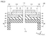
- FIG. 3 is a cross-sectional view of the piezoelectric transducer shown in FIG. 1 as seen from the direction of arrow III-III.
- FIG. 5 is a cross-sectional view showing a state in which a lower electrode layer is provided on the lower surface of a single crystal piezoelectric layer in the method for manufacturing a piezoelectric transducer according to the embodiment of the present invention.
- FIG. 5 is a cross-sectional view showing a state in which an intermediate layer is provided on the lower surface of each of the lower electrode layer and the single crystal piezoelectric layer in the method for manufacturing a piezoelectric transducer according to the embodiment of the present invention.
- FIG. 6 is a cross-sectional view showing a prepared substrate in the method for manufacturing the piezoelectric transducer according to the embodiment of the present invention.
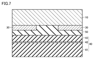
- FIG. 7 is a cross-sectional view showing a state where the plurality of layers shown in FIG. 5 are bonded to the substrate shown in FIG. 6 in the method for manufacturing the piezoelectric transducer according to the embodiment of the present invention.
- FIG. 6 is a cross-sectional view showing a prepared substrate in the method for manufacturing the piezoelectric transducer according to the embodiment of the present invention.
- FIG. 7 is a cross-sectional view showing a state where the plurality of layers shown in FIG. 5 are bonded to the substrate shown in FIG. 6 in the method for manufacturing the piezo
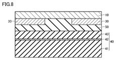
- FIG. 5 is a diagram showing a state in which the upper surface of the single crystal piezoelectric layer is cut in the method for manufacturing the piezoelectric transducer according to the embodiment of the present invention.
- FIG. 5 is a cross-sectional view showing a state in which an upper electrode layer is provided on the upper surface of a single crystal piezoelectric layer in the method for manufacturing a piezoelectric transducer according to the embodiment of the present invention.
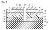
- FIG. 6 is a cross-sectional view showing a state in which a hole portion in a single crystal piezoelectric layer and a gap portion between a plurality of beam portions are formed in the method for manufacturing a piezoelectric transducer according to the embodiment of the present invention.
- FIG. 10 is a perspective view showing a state where each of a plurality of beam portions is displaced to the uppermost side during driving of the piezoelectric transducer according to the comparative example.
- FIG. 5 is a perspective view showing a state where each of a plurality of beam portions is displaced to the uppermost side during driving of the piezoelectric transducer according to the embodiment of the present invention.
- It is a top view showing composition of a piezoelectric transducer concerning a 1st modification of one embodiment of the present invention.
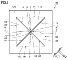
- FIG. 1 is a plan view showing the configuration of a piezoelectric transducer according to an embodiment of the present invention.
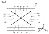
- FIG. 2 is a front perspective view showing the configuration of the piezoelectric transducer according to the embodiment of the present invention.
- FIG. 3 is a cross-sectional view of the piezoelectric transducer shown in FIG. 1 as seen from the direction of arrow III-III. It should be noted that in FIGS. 1 and 2, the boundaries between the layers forming the piezoelectric transducer are not shown.
- the piezoelectric transducer 100 includes a plurality of beam portions 110 and a base portion 120.
- each of the plurality of beam portions 110 has a fixed end portion 111 and a tip end portion 112.
- Each of the plurality of beam portions 110 extends in a direction away from the fixed end portion 111.
- the tip portion 112 is located at the tip in the extending direction E from the fixed end portion 111 in each of the plurality of beam portions 110.
- Each of the plurality of beam portions 110 extends in the same plane.
- Each of the plurality of beam portions 110 has a tapered outer shape in the extending direction E when viewed from a direction perpendicular to the plane.
- each of the plurality of beam portions 110 has a triangular outer shape when viewed from a direction perpendicular to the plane.
- this triangular shape is an isosceles triangular shape having the fixed end portion 111 as the base and the tip end 112 as the apex. That is, the extending direction E of each of the plurality of beam portions 110 is a direction that connects the midpoint and the apex of the base of the isosceles triangular shape that is the outer shape of each beam portion 110.
- each of the plurality of beam portions 110 may have an outer shape having a constant width in the extending direction E, or may have a width in the extending direction E. May have a gradually increasing outer shape.
- Each of the plurality of beam portions 110 may have a rectangular outer shape. A piezoelectric transducer according to a modified example in which the shape and arrangement of the beam portion 110 are different will be described later.
- the piezoelectric transducer 100 includes four beam portions 110. As described above, the piezoelectric transducer 100 according to the present embodiment includes, as the plurality of beam portions 110, three or more beam portions 110.
- each of the plurality of beam portions 110 is arranged so as to be point-symmetric with respect to the virtual center point C of the piezoelectric transducer 100 when viewed from a direction perpendicular to the plane. ..
- each of the four beam portions 110 extends in mutually different directions within the plane and extends between adjacent beam portions 110 when viewed from a direction perpendicular to the plane.
- the directions E are different from each other by 90°.
- the extending directions E of at least two beam portions 110 of the plurality of beam portions 110 are different from each other.
- the plurality of beam portions 110 may include the beam portions 110 having the same extending direction E.
- the extending direction E of each of the plurality of beam portions 110 extends toward the virtual center point C when viewed from the direction perpendicular to the plane.
- the extending direction E of each of the plurality of beam portions 110 may extend away from the virtual center point.
- a piezoelectric transducer according to a modified example having a plurality of beam portions having different extending directions E from the present embodiment will be described later.
- each of the plurality of beam portions 110 is located apart from each other with a gap 113 interposed therebetween.
- the gaps 113 located between the plurality of beam portions 110 extend radially from the virtual center point C when viewed from the direction perpendicular to the plane.
- the width of the gap 113 is substantially constant in the direction in which the gap 113 extends.
- the plurality of beam portions 110 when viewed in a direction perpendicular to the plane, the plurality of beam portions 110 extend in different directions in the plane, and the intervals between the adjacent beam portions 110 are equal to each other. So that it is arranged.
- the base 120 is connected to the fixed end 111 of each of the plurality of beams 110.
- the tip 112 of each of the plurality of beams 110 is a free end spaced from the base 120.
- the tip 112 of each of the plurality of beams 110 may be connected to a plate-like portion that vibrates up and down when the piezoelectric transducer 100 is driven.
- the piezoelectric transducer according to the modified example having the plate-shaped portion will be described later.
- a recess 115 that opens downward is formed below each of the plurality of beam portions 110 and a gap 113 located between the beam portions 110.
- the portion located above the recess 115 becomes the gap 113 located between each of the plurality of beam portions 110 and between the beam portions 110.
- the piezoelectric transducer includes a single crystal piezoelectric layer 10, an upper electrode layer 20, and a lower electrode layer 30.
- each of the plurality of beam portions 110 includes the single crystal piezoelectric layer 10, the upper electrode layer 20, and the lower electrode layer 30.
- Holes 11 are provided in the single crystal piezoelectric layer 10.
- the hole 11 is formed so as to vertically penetrate the single crystal piezoelectric layer 10.
- the hole 11 is formed so as to be located on the lower electrode layer 30.
- the hole 11 is not shown in FIGS. 1 and 2.
- the single crystal piezoelectric layer 10 constitutes a part of the beam 110 and a part of the base 120.
- the material forming the single crystal piezoelectric layer 10 will be described later.
- the upper electrode layer 20 is arranged above the single crystal piezoelectric layer 10.
- the upper electrode layer 20 is arranged such that at least a part thereof is located above the recess 115.
- the upper electrode layer 20 constitutes a part of the beam portion 110.
- the upper electrode layer 20 is made of a conductive material such as Pt.
- An adhesion layer made of Ti or the like may be arranged between the upper electrode layer 20 and the single crystal piezoelectric layer 10.
- the lower electrode layer 30 is arranged so as to face at least a part of the upper electrode layer 20 with the single crystal piezoelectric layer 10 interposed therebetween.
- the lower electrode layer 30 is arranged such that at least a part of the lower electrode layer 30 is located above the recess 115.
- the lower electrode layer 30 is arranged above the recess 115 so as to face at least a part of the upper electrode layer 20 with the single crystal piezoelectric layer 10 interposed therebetween.
- the lower electrode layer 30 constitutes a part of the beam 110 and a part of the base 120. Further, the end of the lower electrode layer 30 on the side of the gap 113 is not exposed to the gap 113 in the present embodiment, but may be exposed to the gap 113.
- the lower electrode layer 30 is made of a conductive material such as Pt.
- An adhesion layer made of Ti or the like may be disposed between the lower electrode layer 30 and the single crystal piezoelectric layer 10.
- the piezoelectric transducer according to this embodiment further includes a substrate 40.
- the substrate 40 is arranged below the lower electrode layer 30.
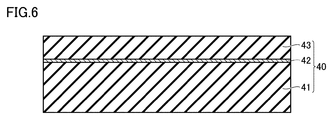
- the substrate 40 includes a handle layer 41, a box layer 42 laminated on the handle layer 41, and an active layer 43 laminated on the box layer 42.
- each of the handle layer 41 and the active layer 43 is made of Si.
- the box layer 42 is made of SiO 2 .
- the substrate 40 is a so-called SOI (Silicon on Insulator) substrate.
- a recess 115 is formed in each of the handle layer 41 and the box layer 42.
- a gap 113 is formed in the active layer 43. That is, each of the handle layer 41 and the box layer 42 constitutes a part of the base 120.
- the active layer 43 constitutes a part of the beam 110 and a part of the base 120.
- An intermediate layer 50 is arranged between the substrate 40 and the lower electrode layer 30, and between the substrate 40 and the single crystal piezoelectric layer 10.
- the intermediate layer 50 is arranged so as to cover each of the lower surface of the lower electrode layer 30 and the lower surface of the single crystal piezoelectric layer 10 where the lower electrode layer 30 is not located, from below.
- the intermediate layer 50 is made of, for example, SiO 2 .
- the piezoelectric transducer 100 by applying a potential difference between the upper electrode layer 20 and the lower electrode layer 30, a portion of the single crystal piezoelectric layer 10 located between the upper electrode layer 20 and the lower electrode layer 30. Can be distorted. Therefore, when the piezoelectric transducer 100 is driven, the plurality of beam portions 110 vibrate so as to bend vertically.
- the piezoelectric transducer 100 according to this embodiment may be used as a receiving element.
- FIG. 4 is a cross-sectional view showing a state in which a lower electrode layer is provided on the lower surface of the single crystal piezoelectric layer in the method for manufacturing a piezoelectric transducer according to the embodiment of the present invention.
- the lower electrode layer 30 is provided on the lower surface of the single crystal piezoelectric layer 10 by a lift-off method, a plating method, an etching method, or the like.
- FIG. 5 is a cross-sectional view showing a state in which an intermediate layer is provided on the lower surface of each of the lower electrode layer and the single crystal piezoelectric layer in the method for manufacturing a piezoelectric transducer according to the embodiment of the present invention.
- an intermediate layer 50 is provided on the lower surface of each of the lower electrode layer 30 and the single crystal piezoelectric layer 10 by a CVD (Chemical Vapor Deposition) method, a PVD (Physical Vapor Deposition) method, or the like.
- CVD Chemical Vapor Deposition
- PVD Physical Vapor Deposition
- FIG. 6 is a sectional view showing a substrate prepared in the method for manufacturing a piezoelectric transducer according to the embodiment of the present invention. As shown in FIG. 6, the substrate 40 in which the recess 115 is not formed is prepared.
- FIG. 7 is a cross-sectional view showing a state in which the plurality of layers shown in FIG. 5 are bonded to the substrate shown in FIG. 6 in the method of manufacturing the piezoelectric transducer according to the embodiment of the present invention. As shown in FIG. 7, the main surface of the substrate 40 on the active layer 43 side is bonded to the lower surface of the intermediate layer 50.
- FIG. 8 is a diagram showing a state where the upper surface of the single crystal piezoelectric layer is cut in the method for manufacturing a piezoelectric transducer according to the embodiment of the present invention. As shown in FIG. 8, the upper surface of the single crystal piezoelectric layer 10 is ground by chemical mechanical polishing (CMP) or the like to make the single crystal piezoelectric layer 10 have a desired thickness.
- CMP chemical mechanical polishing
- FIG. 9 is a cross-sectional view showing a state in which an upper electrode layer is provided on the upper surface of a single crystal piezoelectric layer in the method of manufacturing a piezoelectric transducer according to the embodiment of the present invention.
- the upper electrode layer 20 is provided on a part of the upper surface of the single crystal piezoelectric layer 10 by a lift-off method, a plating method, an etching method, or the like.
- FIG. 10 is a cross-sectional view showing a state in which a hole portion in a single crystal piezoelectric layer and a gap portion between a plurality of beam portions are formed in a method of manufacturing a piezoelectric transducer according to an embodiment of the present invention.
- the holes 11 are provided in the single crystal piezoelectric layer 10 by the lift-off method, the plating method, the etching method, or the like.
- the lift-off method, the plating method, the etching method, or the like the single crystal piezoelectric layer 10, the upper electrode layer 20, the intermediate layer 50, the active layer 43, and the box layer 42 are provided between the plurality of beam portions 110.
- a gap 113 located at is provided.
- the recess 115 is formed in the substrate 40 by performing deep reactive ion etching (Deep RIE) on the substrate 40 from the lower main surface of the substrate 40.
- Deep RIE deep reactive ion etching
- the piezoelectric transducer 100 according to the embodiment of the present invention as shown in FIG. 3 is manufactured by the above process.
- the single crystal piezoelectric layer 10 is composed of lithium niobate (LiNbO 3 ) or lithium tantalate (LiTaO 3 ). Each of lithium niobate and lithium tantalate is a ceramic material having relatively high piezoelectric characteristics.
- the crystal structures of lithium niobate and lithium tantalate belong to the trigonal system.
- the trigonal system is a crystal system having three-fold rotational symmetry with respect to the principal axis.
- the polarization axes of lithium niobate and lithium tantalate extend along the axial direction of the trigonal principal axis in each crystal structure.
- the elastic modulus is significantly different from the other directions only in the axial direction of the polarization axis.
- the single crystal piezoelectric layer 10 has a polarization axis Z′ oriented in one direction.
- the polarization axis Z' has a polarization component in the same plane in which each of the plurality of beam portions 110 extends.
- the polarization axis Z′ is inclined and intersects the plane in which each of the plurality of beam portions 110 extends.
- the polarization axis Z' may extend only in the plane.
- Each of lithium niobate and lithium tantalate used as the material of the single crystal piezoelectric layer 10 is X-cut or Y-cut so that the polarization axis Z′ has a polarization component extending in the plane direction.
- the polarization axis Z′ extends only in the above plane. That is, the angle formed by the polarization axis Z′ and the plane is always 0°.
- the angle formed by the polarization axis Z′ and the plane changes depending on the cut angle that is the cut-out angle of the crystal. It changes a lot.
- the cut angle of the Y-cut is preferably 20° or more and 35° or more, and most preferably 26°.
- the single crystal piezoelectric layer 10 is composed of lithium niobate Y-cut at a cut angle of 30°.
- the single crystal piezoelectric layer 10 has the polarization axis Z′ which is oriented in one direction and has a polarization component in the plane. That is, the polarization axes Z′ of the single crystal piezoelectric layers 10 included in each of the plurality of beam portions 110 are all oriented in the same direction.
- the axial direction of the polarization axis Z′ has a component only in one direction within the plane in which each of the plurality of beam portions 110 extends.
- the piezoelectric transducer 100 having a polarization component in the plane has an improved electrical-mechanical conversion efficiency.
- the polarization axis Z′ is orthogonal to the polarization component that the plane has. It has an axis X'. That is, as shown in FIGS. 1 to 3, the axial direction of the orthogonal axis X'is orthogonal to the polarization axis Z'and extends in the plane.
- the polarization axis Z'of the single crystal piezoelectric layer 10 has no component in the axial direction of the orthogonal axis X'.
- the single crystal piezoelectric layer 10 further has a third axis Y'which is orthogonal to each of the polarization axis Z'and the orthogonal axis X'.
- the bending elastic modulus of the single crystal piezoelectric layer 10 is large between the direction Z 1 ′ of the polarization component of the polarization axis Z′ in the plane and the axial direction of the orthogonal axis X′. different.
- the single crystal piezoelectric layer 10 flexural modulus at 'polarization component direction Z 1 having the' polarization axis Z in the above plane are small, single-crystal piezoelectric layer 10 bending elastically in the axial direction of the orthogonal axes X ' The rate is high.
- the plurality of beam portions 110 each include a beam portion extending in the polarization component direction Z 1 ′ and a beam portion extending in the axial direction of the orthogonal axis X′.
- the piezoelectric transducer 100 is configured so that it does not exist.
- the plurality of beam portions include both a beam portion extending in the polarization component direction and a beam portion extending in the axial direction of the orthogonal axis X′. explain.
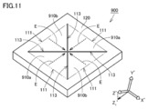
- FIG. 11 is a perspective view showing a configuration of a piezoelectric transducer according to a comparative example.
- the angular relationship between the polarization component direction in the single crystal piezoelectric layer and the axial direction of the orthogonal axis X′ and the extending direction of each of the plurality of beam portions is as follows.
- the piezoelectric transducer 100 according to the present embodiment has the same configuration as that of the piezoelectric transducer 100 according to the present embodiment except that the angular relationship is different.
- the piezoelectric transducer 900 according to the comparative example has two beam portions 910a extending in the polarization component direction and two beam portions 910b extending in the axial direction of the orthogonal axis X'. Therefore, in the piezoelectric transducer 900 according to the comparative example, each of the two beam portions 910a extending in the polarization component direction and each of the two beam portions 910b extending in the direction intersecting the polarization component direction, The flexural moduli differ greatly from each other.
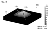
- FIG. 12 is a perspective view of a piezoelectric transducer according to a comparative example, showing a state in which each of a plurality of beam portions is displaced to the uppermost side during driving.
- FIG. 12 in the piezoelectric transducer 900 according to the comparative example, when driven, each of the two beam portions 910a extending in the polarization component direction and the two beam portions 910a extending in the axial direction of the orthogonal axis X'.
- the maximum displacement in the vertical direction is significantly different from each of the beam portions 910b. Therefore, the gap between the beam portions 910a and 910b that extend in different directions in the plane and are adjacent to each other becomes wider during driving.
- each of the polarization component direction Z 1 ′ and the orthogonal axis X′ is extended in each of the plurality of beam portions 110. It intersects with the current direction E. That is, each of the plurality of beam portions 110 does not include the beam portion extending in the polarization component direction Z 1 ′ and the beam portion extending in the axial direction of the orthogonal axis X′.
- the angle formed by the extending direction E of each of the plurality of beam portions 110 and the axial direction of the orthogonal axis X′ is 40 degrees or more and 50 degrees or less.
- the bending elastic modulus of each of the plurality of beam portions 110 including the single crystal piezoelectric layer 10 is made uniform.
- the angle formed by the extending direction E of each of the plurality of beam portions 110 and the axial direction of the orthogonal axis X′ is 45 degrees. In this case, the bending elastic modulus of each of the plurality of beam portions 110 can be made most uniform.
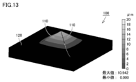
- FIG. 13 is a perspective view showing a state where each of the plurality of beam portions is displaced to the uppermost position during driving of the piezoelectric transducer according to the embodiment of the present invention.
- the piezoelectric transducer 100 according to the present embodiment since the bending elastic modulus of each of the plurality of beam portions 110 is made uniform, each of the plurality of beam portions 110 moves vertically when driven. Displaces substantially uniformly in the direction. Therefore, the difference between the deformation amounts of the plurality of beam portions 110 of the piezoelectric transducer 100 according to the present embodiment is smaller than the difference between the deformation amounts of the plurality of beam portions 910a and 910b of the piezoelectric transducer 900 according to the comparative example. ing.
- the gap between the beam portions 110 that are adjacent to each other while extending in different directions in the plane is kept narrower during driving than the gap between the beam portions 910a and 910b according to the comparative example.
- the single crystal piezoelectric layer 10 has the polarization axis Z′ oriented in one direction.
- the polarization axis Z' has a polarization component in the plane.
- the axial direction of the orthogonal axis X′ which is orthogonal to the polarization axis Z′ and extends in the plane, intersects the extending direction E of each of the plurality of beam portions 110.
- the plurality of beam portions 110 may not include each of the beam portion extending in the polarization component direction Z 1 ′ and the beam portion extending in the axial direction of the orthogonal axis X′. Therefore, the difference in mechanical characteristics between the plurality of beam portions 110 can be reduced. Further, in one embodiment of the present invention, specifically, the flexural modulus of each of the plurality of beam portions can be made uniform. Accordingly, when the piezoelectric transducer 100 according to the present embodiment is driven, it is possible to reduce a difference in mechanical characteristics such as a resonance frequency and a deformation amount of each of the plurality of beam portions 110, so that the input/output characteristics of the piezoelectric transducer 100 are reduced. Can be improved.
- the angle formed between the extending direction E of each of the plurality of beam portions 110 and the axial direction of the orthogonal axis X′ is 40 degrees or more and 50 degrees or less.
- the angle between the direction intersecting the polarization component direction Z 1 'in the plane is 50 degrees 40 degrees in all of the beam portion 110
- the bending elastic modulus of each of the plurality of beam portions 110 can be made more uniform. Accordingly, when the piezoelectric transducer 100 is driven, the difference in mechanical characteristics such as the resonance frequency and the deformation amount of each of the plurality of beam portions 110 can be further reduced, so that the input/output characteristics of the piezoelectric transducer 100 can be effectively improved.
- the single crystal piezoelectric layer 10 is made of lithium niobate or lithium tantalate.
- the crystal structures of lithium niobate and lithium tantalate belong to the trigonal system. Since the polarization axes of lithium niobate and lithium tantalate extend along the axial direction of the trigonal principal axis in each crystal structure, the polarization axis is extremely longer than other piezoelectric ceramic materials. .. Further, the trigonal system is a crystal system having three-fold rotational symmetry with respect to the principal axis.
- the single crystal piezoelectric body is formed in the polarization component direction Z 1 ′ and the orthogonal axis X′.
- the flexural moduli of the layers 10 are very different.
- the single crystal piezoelectric layer 10 is made of lithium niobate or lithium tantalate, the extending direction E of each of the plurality of beam portions 110 and the axial direction of the orthogonal axis X′ are By satisfying the above relationship, it is possible to make the bending elastic modulus of each of the plurality of beam portions 110 uniform while configuring the single crystal piezoelectric layer 10 with a material having high piezoelectric characteristics. As a result, the input/output characteristics of the piezoelectric transducer can be improved.
- the polarization axis Z′ may extend only in the above plane.
- X-cut lithium niobate or X-cut lithium tantalate is used as the material of the single crystal piezoelectric layer 10.
- the angle formed by the polarization axis Z′ and the plane is It is always 0°.
- each of the plurality of beam portions 110 has a triangular or quadrangular outer shape when viewed from a direction perpendicular to the plane, Are arranged so that the intervals between adjacent beam portions 110 extending in different directions are equal to each other.
- the bending elastic moduli of the plurality of beam portions 110 are made uniform, the amount of change in each gap 113 due to the variation of each of the plurality of beam portions 110 during driving is made uniform, and the piezoelectric elements are piezoelectric.
- the input/output characteristics of the transducer 100 can be improved.
- a piezoelectric transducer according to each modified example of the present embodiment will be described below with reference to the drawings. The description of the same configuration as the piezoelectric transducer 100 according to the embodiment of the present invention will not be repeated.
- FIG. 14 is a plan view showing the configuration of the piezoelectric transducer according to the first modified example of the embodiment of the present invention.
- the piezoelectric transducer 100a according to the first modification of the embodiment of the present invention includes a plurality of beam portions 110a and a base portion 120a.
- Each of the plurality of beam portions 110a extends in the same plane, and has an outer shape in which the width gradually increases in the extending direction Ea when viewed from a direction perpendicular to this plane. .. Specifically, each of the plurality of beam portions 110a has a trapezoidal outer shape with the fixed end portion 111a as the upper bottom when viewed from the direction perpendicular to the plane.
- each of the plurality of beam portions 110a extends away from the virtual center point Ca of the piezoelectric transducer 100a when viewed from the direction perpendicular to the plane.
- the piezoelectric transducer 100a further includes a peripheral wall portion 130a arranged so as to surround the plurality of beam portions 110a when viewed from a direction perpendicular to the plane.
- the tip 112a of each of the plurality of beams 110a and the peripheral wall 130a are separated from each other.
- the base portion 120a and the peripheral wall portion 130a are directly or indirectly connected to each other below the plurality of beam portions 110a in the stacking direction.
- the axial direction of the orthogonal axis X′ intersects the extending direction Ea of each of the plurality of beam portions 110a.
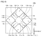
- FIG. 15 is a plan view showing the configuration of the piezoelectric transducer according to the second modified example of the embodiment of the present invention.
- the piezoelectric transducer 100b according to the second modification of the embodiment of the present invention is different from the piezoelectric transducer 100a according to the first modification of the embodiment only in the shape of each of the plurality of beam portions. Different.
- each of the plurality of beam portions 110b extends in the same plane.
- Each of the plurality of beam portions 110b has an outer shape having a constant width in the extending direction Eb when viewed from a direction perpendicular to the plane.
- each of the plurality of beam portions 110b has a rectangular outer shape when viewed from a direction perpendicular to the plane.
- the gap 113b located between the plurality of beam portions 110b has a substantially square shape when viewed from the direction perpendicular to the plane. ..
- the axial direction of the orthogonal axis X′ intersects the extending direction Eb of each of the plurality of beam portions 110b.
- FIG. 16 is a plan view showing the configuration of the piezoelectric transducer according to the third modified example of the embodiment of the present invention. As shown in FIG. 16, in the piezoelectric transducer 100c according to the third modified example of the embodiment of the present invention, each of the plurality of beam portions 110c extends in the same plane.
- Each of the plurality of beam portions 110c has a trapezoidal outer shape with the fixed end portion 111c as a lower bottom when viewed from a direction perpendicular to this plane. Therefore, a substantially rectangular gap is formed in the central portion of the piezoelectric transducer 100c so as to be surrounded by the tip portions 112c of the plurality of beam portions 110c.
- the axial direction of the orthogonal axis X′ intersects the extending direction E of each of the plurality of beam portions 110c.
- FIG. 17 is a plan view showing the configuration of the piezoelectric transducer according to the fourth modified example of the embodiment of the present invention.
- a piezoelectric transducer 100d according to a fourth modified example of the embodiment of the present invention includes a plurality of beam portions 110d and a base portion 120d, and further includes a plate-shaped portion 140d.
- Each of the plurality of beam portions 110d extends in the same plane.
- Each of the plurality of beam portions 110d has a rectangular outer shape when viewed from a direction perpendicular to this plane.
- the tip 112d of each of the plurality of beams 110d is connected to the plate-shaped portion 140d.
- the plate-shaped portion 140d has a circular outer shape centered on the virtual center point Cd of the piezoelectric transducer 100d when viewed from a direction perpendicular to the plane.
- the plate-shaped portion 140d is not connected to the base portion 120d and is separated. Therefore, when the piezoelectric transducer 100d is driven, each of the plurality of beam portions 110d is displaced in the vertical direction, so that the plate-shaped portion 140d is moved in the vertical direction.
- the edge portion on the base 120d side in the gap 113d between the adjacent beam portions 110d extending in different directions in the plane is the virtual center point Cd. It is an arc shape of a circle centered on.
- the axial direction of the orthogonal axis X′ intersects the extending direction E of each of the plurality of beam portions 110d.
- the difference in stress in the extending direction E between the plurality of beam portions 110d can be reduced. Therefore, with respect to the stress applied to the plurality of connecting portions that connect the plurality of beam portions 110d and the plate-shaped portion 140d to each other, the difference in stress between the connecting portions can be reduced. As a result, the reliability of the piezoelectric transducer 100d can be improved.
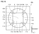
- FIG. 18 is a plan view showing the configuration of the piezoelectric transducer according to the fifth modified example of the embodiment of the present invention. As shown in FIG. 18, the piezoelectric transducer 100e according to the fifth modification of the embodiment of the present invention is different from the piezoelectric transducer 100d according to the fourth modification of the embodiment only in the outer shape of the plate-shaped portion. ..
- each of the plurality of beam portions 110e extends in the same plane.
- the plate-shaped portion 140e has a substantially square outer shape with the virtual center point Ce of the piezoelectric transducer 100e as the center.
- the tip end 112e of each of the plurality of beam portions 110e is connected to the plate-shaped portion 140e at each substantially square vertex of the plate-shaped portion 140e.
- the axial direction of the orthogonal axis X′ intersects the extending direction E of each of the plurality of beam portions 110e.
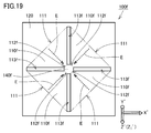
- FIG. 19 is a plan view showing the configuration of the piezoelectric transducer according to the sixth modified example of the embodiment of the present invention.
- the piezoelectric transducer 100f according to the sixth modified example of the embodiment of the present invention is different from the piezoelectric transducer 100d according to the fourth modified example of the present embodiment in the outer shape of each of the plurality of beam portions.
- the outer shape of the plate portion is different.
- each of the plurality of beam portions 110f extends in the same plane.
- Each of the plurality of beam portions 110f has a tapered outer shape in the extending direction E when viewed from a direction perpendicular to this plane.
- each of the plurality of beam portions 110f has a trapezoidal outer shape when viewed from a direction perpendicular to the plane.
- the width of the gap 113 is substantially constant in the extending direction of the gap 113f.
- the plate-shaped portion 140f has a polygonal outer shape when viewed from a direction perpendicular to the plane.
- the plate-shaped portion 140f has an octagonal outer shape when viewed from a direction perpendicular to the plane.
- the tip end portion 112f of each of the plurality of beam portions 110f is connected to the plate-shaped portion 140f at each of the polygonal sides of the plate-shaped portion 140f.
- the axial direction of the orthogonal axis X′ intersects the extending direction E of each of the plurality of beam portions 110f.
- FIG. 20 is a plan view showing the configuration of the piezoelectric transducer according to the seventh modified example of the embodiment of the present invention.
- the piezoelectric transducer 100g according to the seventh modified example of the embodiment of the present invention is different from the sixth modified example of the present embodiment mainly in that a plurality of plate-shaped portions are provided. This is different from the piezoelectric transducer 100f.
- each of the plurality of beam portions 110g extends in the same plane.
- Each of the plurality of beam portions 110g has a triangular outer shape when viewed from a direction perpendicular to the plane.
- the piezoelectric transducer 100g includes a plurality of plate-shaped portions 140g.
- Each of the plurality of plate-shaped portions 140g is located in each of the plurality of gaps 113g, and connects two adjacent beam portions 110g to each other.
- Each of the plurality of plate-shaped portions 140g has a rectangular outer shape when viewed from a direction perpendicular to the plane.
- the axial direction of the orthogonal axis X′ intersects the extending direction E of each of the plurality of beam portions 110g.
Landscapes
- Chemical & Material Sciences (AREA)
- Engineering & Computer Science (AREA)
- Materials Engineering (AREA)
- Ceramic Engineering (AREA)
- Transducers For Ultrasonic Waves (AREA)
- Piezo-Electric Transducers For Audible Bands (AREA)
Abstract
L'invention concerne un transducteur piézoélectrique comportant une pluralité de parties de poutre (110) dont chacune comprend une partie d'extrémité fixe (111) et s'étend dans une direction opposée à la partie d'extrémité fixe (111). Une partie de base (120) est reliée à la partie d'extrémité fixe (111) de chacune de la pluralité de parties de poutre (110). Chacune de la pluralité de parties de poutre (110) s'étend dans le même plan. Parmi la pluralité de parties de poutre (110), au moins deux parties de poutre (110) présentent des directions d'extension (E) mutuellement différentes. Chacune de la pluralité de parties de poutre (110) comprend une seule couche de corps piézoélectrique monocristalline (10) présentant un axe de polarisation orienté dans la même direction, une couche d'électrode supérieure (20) et une couche d'électrode inférieure (30). Un axe de polarisation (Z') présente une composante de polarisation dans le plan. La direction axiale d'un axe orthogonal (X') orthogonal à l'axe de polarisation (Z') et s'étendant dans le plan croise la direction d'extension (E) de chacune de la pluralité de parties de poutre (110).
Priority Applications (4)
| Application Number | Priority Date | Filing Date | Title |
|---|---|---|---|
| JP2020559726A JP7088314B2 (ja) | 2018-12-10 | 2019-09-04 | 圧電トランスデューサ |
| CN201980076900.5A CN113169266B (zh) | 2018-12-10 | 2019-09-04 | 压电换能器 |
| DE112019006130.5T DE112019006130B4 (de) | 2018-12-10 | 2019-09-04 | Piezoelektrischer Wandler |
| US17/205,062 US11832522B2 (en) | 2018-12-10 | 2021-03-18 | Piezoelectric transducer |
Applications Claiming Priority (2)
| Application Number | Priority Date | Filing Date | Title |
|---|---|---|---|
| JP2018230898 | 2018-12-10 | ||
| JP2018-230898 | 2018-12-10 |
Related Child Applications (1)
| Application Number | Title | Priority Date | Filing Date |
|---|---|---|---|
| US17/205,062 Continuation US11832522B2 (en) | 2018-12-10 | 2021-03-18 | Piezoelectric transducer |
Publications (1)
| Publication Number | Publication Date |
|---|---|
| WO2020121609A1 true WO2020121609A1 (fr) | 2020-06-18 |
Family
ID=71075519
Family Applications (1)
| Application Number | Title | Priority Date | Filing Date |
|---|---|---|---|
| PCT/JP2019/034707 Ceased WO2020121609A1 (fr) | 2018-12-10 | 2019-09-04 | Transducteur piézoélectrique |
Country Status (5)
| Country | Link |
|---|---|
| US (1) | US11832522B2 (fr) |
| JP (1) | JP7088314B2 (fr) |
| CN (1) | CN113169266B (fr) |
| DE (1) | DE112019006130B4 (fr) |
| WO (1) | WO2020121609A1 (fr) |
Cited By (8)
| Publication number | Priority date | Publication date | Assignee | Title |
|---|---|---|---|---|
| WO2021153491A1 (fr) * | 2020-01-28 | 2021-08-05 | 株式会社村田製作所 | Dispositif piézoélectrique |
| JP2022013874A (ja) * | 2020-07-02 | 2022-01-18 | エクスメムス ラブズ,インコーポレイテッド | 発声装置、パッケージ構造並びに発声チップ、パッケージ構造及び発声装置を製造する方法 |
| JPWO2022049944A1 (fr) * | 2020-09-07 | 2022-03-10 | ||
| WO2022168826A1 (fr) * | 2021-02-03 | 2022-08-11 | 株式会社デンソー | Élément piézoélectrique, dispositif piézoélectrique et procédé de fabrication d'élément piézoélectrique |
| CN115334441A (zh) * | 2021-05-11 | 2022-11-11 | 知微电子有限公司 | 发声单元以及其制造方法 |
| WO2023135853A1 (fr) * | 2022-01-11 | 2023-07-20 | 株式会社村田製作所 | Transducteur |
| US11805342B2 (en) | 2019-09-22 | 2023-10-31 | xMEMS Labs, Inc. | Sound producing package structure and manufacturing method thereof |
| US12641370B2 (en) | 2021-05-11 | 2026-05-26 | xMEMS Labs, Inc. | Package structure, apparatus and forming methods thereof |
Citations (4)
| Publication number | Priority date | Publication date | Assignee | Title |
|---|---|---|---|---|
| WO2007060768A1 (fr) * | 2005-11-24 | 2007-05-31 | Murata Manufacturing Co., Ltd. | Transducteur electroacoustique |
| JP2011004129A (ja) * | 2009-06-18 | 2011-01-06 | Univ Of Tokyo | マイクロフォン |
| JP2011527152A (ja) * | 2008-06-30 | 2011-10-20 | ザ・リージェンツ・オブ・ザ・ユニバーシティ・オブ・ミシガン | 圧電型memsマイクロフォン |
| WO2017094520A1 (fr) * | 2015-12-02 | 2017-06-08 | 株式会社村田製作所 | Élément piézoélectrique, microphone piézoélectrique, résonateur piézoélectrique et procédé de fabrication d'élément piézoélectrique |
Family Cites Families (17)
| Publication number | Priority date | Publication date | Assignee | Title |
|---|---|---|---|---|
| JPS601097A (ja) | 1983-06-15 | 1985-01-07 | Sanshin Ind Co Ltd | パワ−チルト装置 |
| JPH02126798A (ja) | 1988-11-07 | 1990-05-15 | Nec Corp | 圧電振動板とその製造方法 |
| JP2000180180A (ja) * | 1998-12-16 | 2000-06-30 | Toyota Motor Corp | 物理量検出装置及び角速度検出装置 |
| KR20050024346A (ko) * | 2002-06-17 | 2005-03-10 | 브이티아이 테크놀러지즈 오와이 | 모놀리식 실리콘 가속도 센서 제조 방법 |
| JP5239048B2 (ja) * | 2007-07-25 | 2013-07-17 | セイコーインスツル株式会社 | 圧電型加速度センサの製造方法 |
| US10170685B2 (en) * | 2008-06-30 | 2019-01-01 | The Regents Of The University Of Michigan | Piezoelectric MEMS microphone |
| JP4858662B2 (ja) * | 2010-01-12 | 2012-01-18 | ソニー株式会社 | 角速度センサ、電子機器及び角速度の検出方法 |
| JP2012083316A (ja) * | 2010-10-14 | 2012-04-26 | Seiko Epson Corp | 物理量センサー素子、物理量センサーおよび電子機器 |
| US8456061B2 (en) | 2011-01-25 | 2013-06-04 | Hewlett-Packard Development Company, L.P. | Architecture for piezoelectric MEMS devices |
| CN103460721B (zh) * | 2011-03-31 | 2017-05-24 | 韦斯伯技术公司 | 具有间隙控制几何形状的声换能器以及声换能器制造方法 |
| WO2012173081A1 (fr) * | 2011-06-16 | 2012-12-20 | 株式会社村田製作所 | Actionneur piézoélectrique stratifié |
| US20130264913A1 (en) * | 2012-04-10 | 2013-10-10 | Seiko Epson Corporation | Vibrator element, vibration device and electronic apparatus |
| JP6426061B2 (ja) | 2015-07-02 | 2018-11-21 | 富士フイルム株式会社 | 積層薄膜構造体の製造方法、積層薄膜構造体及びそれを備えた圧電素子 |
| JP6867790B2 (ja) | 2016-12-08 | 2021-05-12 | 新日本無線株式会社 | 圧電型memsマイクロフォン |
| WO2020235131A1 (fr) * | 2019-05-17 | 2020-11-26 | 株式会社村田製作所 | Dispositif piézoélectrique |
| CN114830520B (zh) * | 2019-12-17 | 2026-04-24 | 株式会社村田制作所 | 换能器 |
| DE112021004719T5 (de) * | 2020-09-07 | 2023-06-22 | Murata Manufacturing Co., Ltd. | Wandler |
-
2019
- 2019-09-04 WO PCT/JP2019/034707 patent/WO2020121609A1/fr not_active Ceased
- 2019-09-04 JP JP2020559726A patent/JP7088314B2/ja active Active
- 2019-09-04 DE DE112019006130.5T patent/DE112019006130B4/de active Active
- 2019-09-04 CN CN201980076900.5A patent/CN113169266B/zh active Active
-
2021
- 2021-03-18 US US17/205,062 patent/US11832522B2/en active Active
Patent Citations (4)
| Publication number | Priority date | Publication date | Assignee | Title |
|---|---|---|---|---|
| WO2007060768A1 (fr) * | 2005-11-24 | 2007-05-31 | Murata Manufacturing Co., Ltd. | Transducteur electroacoustique |
| JP2011527152A (ja) * | 2008-06-30 | 2011-10-20 | ザ・リージェンツ・オブ・ザ・ユニバーシティ・オブ・ミシガン | 圧電型memsマイクロフォン |
| JP2011004129A (ja) * | 2009-06-18 | 2011-01-06 | Univ Of Tokyo | マイクロフォン |
| WO2017094520A1 (fr) * | 2015-12-02 | 2017-06-08 | 株式会社村田製作所 | Élément piézoélectrique, microphone piézoélectrique, résonateur piézoélectrique et procédé de fabrication d'élément piézoélectrique |
Cited By (20)
| Publication number | Priority date | Publication date | Assignee | Title |
|---|---|---|---|---|
| US11805342B2 (en) | 2019-09-22 | 2023-10-31 | xMEMS Labs, Inc. | Sound producing package structure and manufacturing method thereof |
| WO2021153491A1 (fr) * | 2020-01-28 | 2021-08-05 | 株式会社村田製作所 | Dispositif piézoélectrique |
| US11979713B2 (en) | 2020-01-28 | 2024-05-07 | Murata Manufacturing Co., Ltd. | Piezoelectric device |
| JP2022013874A (ja) * | 2020-07-02 | 2022-01-18 | エクスメムス ラブズ,インコーポレイテッド | 発声装置、パッケージ構造並びに発声チップ、パッケージ構造及び発声装置を製造する方法 |
| JP7232871B2 (ja) | 2020-07-02 | 2023-03-03 | エクスメムス ラブズ,インコーポレイテッド | 発声装置、パッケージ構造並びに発声チップ、パッケージ構造及び発声装置を製造する方法 |
| JPWO2022049944A1 (fr) * | 2020-09-07 | 2022-03-10 | ||
| WO2022049944A1 (fr) * | 2020-09-07 | 2022-03-10 | 株式会社村田製作所 | Transducteur |
| CN116325803B (zh) * | 2020-09-07 | 2026-01-09 | 株式会社村田制作所 | 换能器 |
| US12262176B2 (en) | 2020-09-07 | 2025-03-25 | Murata Manufacturing Co., Ltd. | Transducer |
| JP7226660B2 (ja) | 2020-09-07 | 2023-02-21 | 株式会社村田製作所 | トランスデューサ |
| CN116325803A (zh) * | 2020-09-07 | 2023-06-23 | 株式会社村田制作所 | 换能器 |
| JP2022119126A (ja) * | 2021-02-03 | 2022-08-16 | 株式会社デンソー | 圧電素子、圧電装置、および圧電素子の製造方法 |
| JP7528804B2 (ja) | 2021-02-03 | 2024-08-06 | 株式会社デンソー | 圧電素子、圧電装置、および圧電素子の製造方法 |
| JP2024133375A (ja) * | 2021-02-03 | 2024-10-01 | 株式会社デンソー | 圧電素子、圧電装置 |
| JP7772148B2 (ja) | 2021-02-03 | 2025-11-18 | 株式会社デンソー | 圧電素子、圧電装置 |
| WO2022168826A1 (fr) * | 2021-02-03 | 2022-08-11 | 株式会社デンソー | Élément piézoélectrique, dispositif piézoélectrique et procédé de fabrication d'élément piézoélectrique |
| CN115334441A (zh) * | 2021-05-11 | 2022-11-11 | 知微电子有限公司 | 发声单元以及其制造方法 |
| CN115334441B (zh) * | 2021-05-11 | 2026-04-28 | 知微电子有限公司 | 发声单元以及其制造方法 |
| US12641370B2 (en) | 2021-05-11 | 2026-05-26 | xMEMS Labs, Inc. | Package structure, apparatus and forming methods thereof |
| WO2023135853A1 (fr) * | 2022-01-11 | 2023-07-20 | 株式会社村田製作所 | Transducteur |
Also Published As
| Publication number | Publication date |
|---|---|
| US11832522B2 (en) | 2023-11-28 |
| JP7088314B2 (ja) | 2022-06-21 |
| CN113169266A (zh) | 2021-07-23 |
| JPWO2020121609A1 (ja) | 2021-09-30 |
| US20210202824A1 (en) | 2021-07-01 |
| DE112019006130T5 (de) | 2021-08-26 |
| CN113169266B (zh) | 2024-09-17 |
| DE112019006130B4 (de) | 2022-03-24 |
Similar Documents
| Publication | Publication Date | Title |
|---|---|---|
| JP7088314B2 (ja) | 圧電トランスデューサ | |
| US11979713B2 (en) | Piezoelectric device | |
| CN108140723B (zh) | 压电元件、压电传声器、压电谐振子以及压电元件的制造方法 | |
| JP7031759B2 (ja) | 圧電トランスデューサ | |
| US11495728B2 (en) | Piezoelectric device and method of manufacturing piezoelectric device | |
| US12262176B2 (en) | Transducer | |
| JP6451078B2 (ja) | 光走査装置 | |
| WO2021124611A1 (fr) | Transducteur | |
| US12185636B2 (en) | Piezoelectric device including base portion and membrane portion | |
| CN113228708B (zh) | 压电换能器 | |
| US20080297001A1 (en) | Miniaturizable Motor | |
| JP2010226610A (ja) | 屈曲振動片およびそれを用いた発振器 | |
| WO2023058713A1 (fr) | Procédé de fabrication d'un élément à ondes élastiques et élément à ondes élastiques | |
| JP7545672B2 (ja) | 共振装置、集合基板、及び共振装置の製造方法 | |
| US12507594B2 (en) | Piezoelectric device | |
| WO2020136983A1 (fr) | Transducteur piézoélectrique | |
| WO2023135853A1 (fr) | Transducteur | |
| US20250365542A1 (en) | Transducer | |
| WO2022107606A1 (fr) | Dispositif à ondes élastiques | |
| WO2020129296A1 (fr) | Transducteur piézoélectrique | |
| WO2026088985A1 (fr) | Vibreur et gyroscope de type à modulation de fréquence | |
| JP5561377B2 (ja) | 音片型圧電振動子及び音叉型圧電振動子 | |
| JP2024049642A (ja) | 振動素子の製造方法 |
Legal Events
| Date | Code | Title | Description |
|---|---|---|---|
| 121 | Ep: the epo has been informed by wipo that ep was designated in this application |
Ref document number: 19897294 Country of ref document: EP Kind code of ref document: A1 |
|
| ENP | Entry into the national phase |
Ref document number: 2020559726 Country of ref document: JP Kind code of ref document: A |
|
| 122 | Ep: pct application non-entry in european phase |
Ref document number: 19897294 Country of ref document: EP Kind code of ref document: A1 |