WO2020121657A1 - 圧延用ワークロールおよびこれを備えた圧延機ならびに圧延方法 - Google Patents
圧延用ワークロールおよびこれを備えた圧延機ならびに圧延方法 Download PDFInfo
- Publication number
- WO2020121657A1 WO2020121657A1 PCT/JP2019/041848 JP2019041848W WO2020121657A1 WO 2020121657 A1 WO2020121657 A1 WO 2020121657A1 JP 2019041848 W JP2019041848 W JP 2019041848W WO 2020121657 A1 WO2020121657 A1 WO 2020121657A1
- Authority
- WO
- WIPO (PCT)
- Prior art keywords
- rolling
- work roll
- roll
- plating
- surface roughness
- Prior art date
- Legal status (The legal status is an assumption and is not a legal conclusion. Google has not performed a legal analysis and makes no representation as to the accuracy of the status listed.)
- Ceased
Links
Images



Classifications
-
- B—PERFORMING OPERATIONS; TRANSPORTING
- B21—MECHANICAL METAL-WORKING WITHOUT ESSENTIALLY REMOVING MATERIAL; PUNCHING METAL
- B21B—ROLLING OF METAL
- B21B27/00—Rolls, roll alloys or roll fabrication; Lubricating, cooling or heating rolls while in use
- B21B27/02—Shape or construction of rolls
- B21B27/03—Sleeved rolls
- B21B27/032—Rolls for sheets or strips
-
- C—CHEMISTRY; METALLURGY
- C25—ELECTROLYTIC OR ELECTROPHORETIC PROCESSES; APPARATUS THEREFOR
- C25D—PROCESSES FOR THE ELECTROLYTIC OR ELECTROPHORETIC PRODUCTION OF COATINGS; ELECTROFORMING; APPARATUS THEREFOR
- C25D7/00—Electroplating characterised by the article coated
-
- C—CHEMISTRY; METALLURGY
- C25—ELECTROLYTIC OR ELECTROPHORETIC PROCESSES; APPARATUS THEREFOR
- C25D—PROCESSES FOR THE ELECTROLYTIC OR ELECTROPHORETIC PRODUCTION OF COATINGS; ELECTROFORMING; APPARATUS THEREFOR
- C25D5/00—Electroplating characterised by the process; Pretreatment or after-treatment of workpieces
- C25D5/60—Electroplating characterised by the structure or texture of the layers
- C25D5/605—Surface topography of the layers, e.g. rough, dendritic or nodular layers
-
- C—CHEMISTRY; METALLURGY
- C25—ELECTROLYTIC OR ELECTROPHORETIC PROCESSES; APPARATUS THEREFOR
- C25D—PROCESSES FOR THE ELECTROLYTIC OR ELECTROPHORETIC PRODUCTION OF COATINGS; ELECTROFORMING; APPARATUS THEREFOR
- C25D5/00—Electroplating characterised by the process; Pretreatment or after-treatment of workpieces
- C25D5/60—Electroplating characterised by the structure or texture of the layers
- C25D5/615—Microstructure of the layers, e.g. mixed structure
-
- C—CHEMISTRY; METALLURGY
- C25—ELECTROLYTIC OR ELECTROPHORETIC PROCESSES; APPARATUS THEREFOR
- C25D—PROCESSES FOR THE ELECTROLYTIC OR ELECTROPHORETIC PRODUCTION OF COATINGS; ELECTROFORMING; APPARATUS THEREFOR
- C25D5/00—Electroplating characterised by the process; Pretreatment or after-treatment of workpieces
- C25D5/60—Electroplating characterised by the structure or texture of the layers
- C25D5/625—Discontinuous layers, e.g. microcracked layers
-
- B—PERFORMING OPERATIONS; TRANSPORTING
- B21—MECHANICAL METAL-WORKING WITHOUT ESSENTIALLY REMOVING MATERIAL; PUNCHING METAL
- B21B—ROLLING OF METAL
- B21B1/00—Metal-rolling methods or mills for making semi-finished products of solid or profiled cross-section; Sequence of operations in milling trains; Layout of rolling-mill plant, e.g. grouping of stands; Succession of passes or of sectional pass alternations
- B21B1/22—Metal-rolling methods or mills for making semi-finished products of solid or profiled cross-section; Sequence of operations in milling trains; Layout of rolling-mill plant, e.g. grouping of stands; Succession of passes or of sectional pass alternations for rolling plates, strips, bands or sheets of indefinite length
- B21B2001/228—Metal-rolling methods or mills for making semi-finished products of solid or profiled cross-section; Sequence of operations in milling trains; Layout of rolling-mill plant, e.g. grouping of stands; Succession of passes or of sectional pass alternations for rolling plates, strips, bands or sheets of indefinite length skin pass rolling or temper rolling
-
- B—PERFORMING OPERATIONS; TRANSPORTING
- B21—MECHANICAL METAL-WORKING WITHOUT ESSENTIALLY REMOVING MATERIAL; PUNCHING METAL
- B21B—ROLLING OF METAL
- B21B2265/00—Forming parameters
- B21B2265/18—Elongation
-
- B—PERFORMING OPERATIONS; TRANSPORTING
- B21—MECHANICAL METAL-WORKING WITHOUT ESSENTIALLY REMOVING MATERIAL; PUNCHING METAL
- B21B—ROLLING OF METAL
- B21B2267/00—Roll parameters
- B21B2267/10—Roughness of roll surface
-
- B—PERFORMING OPERATIONS; TRANSPORTING
- B21—MECHANICAL METAL-WORKING WITHOUT ESSENTIALLY REMOVING MATERIAL; PUNCHING METAL
- B21B—ROLLING OF METAL
- B21B2267/00—Roll parameters
- B21B2267/28—Elastic moduli of rolls
-
- C—CHEMISTRY; METALLURGY
- C25—ELECTROLYTIC OR ELECTROPHORETIC PROCESSES; APPARATUS THEREFOR
- C25D—PROCESSES FOR THE ELECTROLYTIC OR ELECTROPHORETIC PRODUCTION OF COATINGS; ELECTROFORMING; APPARATUS THEREFOR
- C25D3/00—Electroplating: Baths therefor
- C25D3/02—Electroplating: Baths therefor from solutions
- C25D3/04—Electroplating: Baths therefor from solutions of chromium
Definitions
- the present invention relates to a work roll for rolling for rolling a high-strength steel strip, a rolling mill provided with the work roll, and a rolling method.
- a temper rolling mill that applies a light reduction of, for example, a reduction rate of 1% or less to a steel strip.
- the steel strip is uniformly stretched by a temper rolling mill and its shape is corrected to obtain a predetermined flatness.
- temper rolling improves mechanical properties such as elongation at yield, tensile strength and elongation, and properties of steel strip such as surface roughness.
- high-strength steel sheet having a tensile strength of 980 MPa or more, a very high rolling load is required to secure the elongation required for shape correction.
- Patent Document 1 discloses a method of performing temper rolling with the surface average roughness Ra of a work roll used in temper rolling being in the range of 3.0 to 10.0 ⁇ m.
- Patent Document 2 discloses a method of using, as a roll material, a cemented carbide composed of tungsten carbide (WC) and cobalt (Co) having a Young's modulus of 500 GPa or more in the surface layer portion.
- Patent Document 3 discloses a method of temper rolling with a roll having a roll surface Young's modulus of 450 GPa or more and a surface roughness Ra of 1 ⁇ m or more and 10 ⁇ m or less.
- the surface of the work roll for rolling described in Patent Documents 1 to 3 described above has a predetermined arithmetic average roughness due to the dull processing.
- a shot blasting method, an electric discharge dull machining method, or the like as described in Patent Document 1.
- problems such as a decrease in surface roughness due to wear or progress of cracks may occur.
- repair or replacement work is required, and there is a problem that stable operation of rolling work is difficult.
- the present invention has the following configurations in order to solve these problems.
- a work roll for rolling characterized in that [2] The work roll for rolling according to [1], wherein the uneven layer is formed by depositing granular chromium by chromium plating.
- a temper rolling mill comprising one or more stands equipped with the work roll according to [1] or [2].
- a temper rolling method comprising performing temper rolling with an elongation percentage of 0.2% or more by using one or more temper rolling machines equipped with the work roll for rolling according to [3].
- the work roll for rolling As described above, according to the work roll for rolling, the rolling mill provided with the work roll, and the rolling method, the work roll for rolling having the arithmetic average roughness in the range of 2.0 to 10.0 ⁇ m is formed on the outer peripheral surface of the body.
- the work roll for rolling having the arithmetic average roughness in the range of 2.0 to 10.0 ⁇ m is formed on the outer peripheral surface of the body.
- a concavo-convex layer made of granular chrome it is possible to suppress the occurrence of work roll defects such as a decrease in surface roughness due to wear or the development of cracks even if the rolling distance advances, and a stable operation of rolling work is performed. It can be performed.
- FIG. 1 is a schematic diagram showing a preferred embodiment of a rolling mill 10 using the work roll for rolling of the present invention.
- the rolling mill 10 of FIG. 1 performs temper rolling of a wide steel strip having a tensile strength of 980 MPa or more, for example.
- the temper rolling mill 10 has a pair of rolling work rolls 2 and a backup roll 3 that supports each rolling work roll 2.
- the pay-off reel 5 is arranged in the front stage of the temper rolling mill 10, and the tension reel 6 is arranged in the rear stage of the temper rolling mill 10.
- a bridle roll may be arranged before or after the temper rolling mill 10.
- the work roll 2 for rolling has a structure in which a body 2x made of cemented carbide is fixed to a shaft material, for example.
- the body portion 2x is made of a cemented carbide having a Young's modulus of 450 GPa or more, for example, tungsten carbide (WC) is 86% by mass% and the balance is a cemented carbide.
- WC tungsten carbide
- the rolling work roll 2 is deformed into a flat shape and the rolling work roll 2 and the steel strip 1 come into contact with each other in the roll bite. It is possible to prevent the arc length from increasing and prevent an excessive rolling load from being applied to the work roll 2 for rolling.
- An uneven layer 2y made of granular Cr is formed on a portion of the body 2x corresponding to the roll barrel surface.
- the concavo-convex layer 2y is formed with concavities and convexities including a surface morphology formed by depositing granular chromium by chrome plating, and has an arithmetic average roughness (hereinafter referred to as "surface roughness") Ra of 2. It is formed in the range of 0 to 10.0 ⁇ m.
- the uneven layer 2y may be formed on at least the roll barrel surface of the body 2x, and may be formed on the entire outer peripheral surface of the body 2x.
- the surface roughness Ra of the work roll 2 for rolling is preferably 3.0 ⁇ m or more.
- the surface roughness Ra of the work roll 2 for rolling is preferably 3.0 ⁇ m or more.
- the surface roughness Ra of the uneven layer 2y is more than 4.0 ⁇ m.
- the surface roughness Ra of the uneven layer 2y is larger than 10.0 ⁇ m, it is industrially very difficult to stably perform the work for increasing the surface roughness on the work roll 2 for rolling. It is also undesirable from the viewpoint of roll life. Therefore, the surface roughness Ra of the work roll is preferably 10.0 ⁇ m or less.
- the concavo-convex layer 2y is formed of granular Cr having chromium deposited by chromium plating.
- First, in order to improve the adhesion between the surface of the body 2x and the chrome plating as a pretreatment for the chrome plating, after the surface of the body 2x is polished to have a surface roughness Ra 0.2 ⁇ m, for example. Further, the surface roughness Ra is 0.8 ⁇ m by sandblasting or the like. After that, the surface of the body 2x is cleaned and chromium plated.
- the plating bath temperature is lowered to 50° C. or lower, and the chromium plating is performed under the condition of high current density of 60 A/dm 2 or higher.
- the grain size of Cr crystal grains deposited on the surface of the body portion 2x can be increased. That is, in the hard chrome plating used industrially, the form and hardness of deposited Cr vary depending on the electroplating conditions (plating bath temperature, current density, plating time).
- widely used bright plating is processed under conditions of a plating bath temperature of 50 to 60° C. and a current density of 40 to 60 A/dm 2 in order to smooth the surface.
- the plating bath temperature is lowered to 50° C. or lower and the high current density condition of 60 A/dm 2 or higher is set. In this way, the deposited chromium is made to be granular.
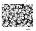
- FIG. 2 is an enlarged surface photograph showing an example of the uneven layer of the work roll for rolling in the temper rolling mill of FIG. 1.
- Chromium plating conditions for the concavo-convex layer 2y in FIG. 2 are as follows: a plating solution containing chromic acid (CrO 3 ) and sulfuric acid (H 2 SO 4 ) is used, a plating bath temperature is 37° C., a current density is 120 A/dm 2 , and plating is performed. The time was set to 150 min. Then, by depositing Cr, a granular uneven layer 2y was formed on the surface of the body 2x. When the surface roughness Ra at this time was measured by a contact type roughness meter, the surface roughness Ra was 3.9 ⁇ m. Further, no cracks or the like were generated on the uneven layer 2y.
- the surface roughness Ra of the uneven layer 2y is controlled by the plating time.
- FIG. 3 shows changes in the surface roughness Ra after plating when only the plating time is changed under the plating conditions of FIG.
- the surface roughness Ra increases as the plating time increases, and can be controlled to a desired surface roughness Ra by changing the plating conditions.
- the average grain size of Cr deposited by chrome plating on the roll surface is 50 ⁇ m or more. This is for effectively exerting the extension effect due to the depression and depression on the surface of the steel sheet.
- the average grain size of Cr By increasing the average grain size of Cr, the interval between the adjacent irregularities can be increased, and the interference between the adjacent irregularities when piercing the surface of the steel sheet and causing plastic deformation can be reduced.
- the four types of work rolls shown in Table 1 were used as work rolls, the roll reduction position was changed, and the relationship between the elongation measured from the change in strip length before and after rolling and the rolling load during rolling was investigated.
- Conventional Example 2 (No. 3) uses tungsten carbide (WC) as a material of the body portion 2x in an amount of 86% by mass% and the balance is made of a cemented carbide and has a Young's modulus of 503 GPa. ..
- Example 1 No. 4
- Example 2 No. 3
- Example 2 No. 3
- Example 3 the same cemented carbide as in Conventional Example 2 (No. 3) was used as the material of the body 2x, and the surface of the body 2x was dulled by chrome plating to obtain a surface roughness.
- FIG. 4 is a graph showing the relationship between elongation rate and width load in Conventional Examples 1 and 2, Comparative Example 1 and Example 1. As shown in FIG. 4, comparing the width loads of Comparative Example 1 (No. 1) in which the roll material is 2% Cr steel and Conventional Example 1 (No. 2), the width load for the same elongation is surface roughness. It is understood that the larger conventional example 1 (No. 2) has a smaller size, and the stretching effect by pushing the convex portion of the surface of the work roll for rolling into the steel plate surface is obtained.
- Example 2 (No. 3) in which the material of the body 2x is cemented carbide, the width load for the same elongation is smaller than that in Conventional Example 1 (No. 2), and the Young's modulus of the roll is It can be seen that the effect of suppressing the flat deformation due to the increase is obtained.
- Example 1 No. 4
- the load was smaller than that of Conventional Example 2 (No. 3) due to both the effect of stretching due to the indentation of the convex portion on the surface of the work roll for rolling and the effect of suppressing the flat deformation of the roll. Therefore, it can be seen that the effect of reducing the rolling load is high.
- the elongation in temper rolling is usually in the range of 0.2 to 1.0%, and in this range, the flatness of the steel strip becomes better as the elongation increases.
- the elongation percentage refers to the rate of change in the length of the steel strip in the longitudinal direction before and after rolling. When the elongation is 0.2% or more, even the high-strength cold-rolled steel strip can be sufficiently shaped, and the flatness of the front surface and the back surface of the steel strip can be substantially improved. Further, in order to make the rolling load applied to the work rolls and the temper rolling mill 10 equal to or lower than the withstand load of the temper rolling mill, the elongation rate applied to the steel strip is preferably 0.5% or less.
- Comparative Example 2 uses a cemented carbide (Young's modulus 503 GPa) containing 86% by weight of tungsten carbide (WC) and the balance of cobalt as the material of the body 2x, and the surface is directly subjected to electric discharge dull machining.
- the surface roughness Ra was finished to 3.0 ⁇ m.
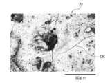
- FIG. 5 shows an enlarged photograph of the surface of the concavo-convex layer when dull machining is performed by direct electric discharge machining on the body 2x of cemented carbide as in Comparative Example 2.
- a crack CK is formed on the surface by an impact during electric discharge machining. It is known that a crack CK occurs when a material such as a cemented carbide, which is mainly composed of brittle ceramics, is subjected to electric discharge machining.
- Example 2 uses a cemented carbide (Young's modulus 503 GPa) containing tungsten carbide (WC) at 86% by mass and balance cobalt as the material of the body 2x, and the surface is plated with chromium.
- Comparative Example 4 uses a cemented carbide (elastic modulus 450 GPa) containing 80% by mass of tungsten carbide (WC) and the balance of cobalt as the material of the body 2x, and discharges without chrome plating. The surface roughness Ra was finished to 4.5 ⁇ m by dull processing.
- Example 3 as the material for the body portion 2x, a cemented carbide (containing elastic modulus 450 GPa) containing 80% by mass of tungsten carbide (WC) and the balance of cobalt was used, and the surface was roughened by chrome plating. Layer 2y was applied and the surface roughness was finished to 4.5 ⁇ m. The average grain size of the Cr deposited at this time was 60 ⁇ m.
- Example 4 is a roll in which granular chromium was deposited on the surface of the roll by the same method as in Example 3 described above, and then the plating conditions were changed and hard chrome plating with a plating thickness of 1 ⁇ m was applied again.
- the reason why the hard chrome plating is performed again by changing the plating conditions is as follows. When granular Cr is deposited on the surface to form irregularities under the plating conditions of low plating bath temperature (50° C. or less) and large current density (60 A/dm 2 ), the Vickers hardness of chromium plating is about 700 to 900. Become. On the other hand, when ordinary hard chrome plating is performed under conditions of a plating bath temperature of 50 to 60° C.
- the hard chrome plating has a Vickers hardness of about 900 to 1100.
- very hard plating was performed on the outermost surface of the work roll for rolling. This is because a film is formed and wear resistance can be further improved.
- the thickness of the hard chrome plating again is set to 1 ⁇ m, because when the plating is performed with a thickness greater than that, the unevenness of the grain formed in the initial stage becomes small and the elongation in temper rolling This is because the effect is reduced. That is, by depositing granular chrome in the initial plating and then again performing hard chrome plating of the thin film, the hardness of the plating film surface can be increased without changing the roughness pattern formed by the granular chrome. .. For this reason, it is desirable that the thickness of the hard chrome plating again be applied within the range of 0.5 to 10 ⁇ m.
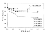
- FIG. 6 is a graph showing changes in roll surface roughness with respect to the rolling length of the work rolls when a rolling experiment was performed using the work rolls for rolling in Table 3.
- Comparative Example 3 in which the 2% Cr steel roll was subjected to the electric discharge dull processing, it was found that the roughness was significantly reduced as the rolling length was increased.
- Comparative Example 4 in which the cemented carbide is made to have a high roughness by direct electric discharge dull machining, since the hardness of the cemented carbide is extremely high, the maintainability of the roll roughness with respect to the rolling length is the best.
- cracks were generated on the roll surface, and further rolling became difficult. This is because, as described above, cracks are formed when direct electric discharge machining is performed on the cemented carbide, and the cracks propagate due to the stress applied during rolling, which makes it difficult to use in actual rolling.
- Example 3 although the roughness decreases due to the initial wear, it can be seen that the roughness retention against the rolling length thereafter is significantly superior to Comparative Example 3. In particular, it can be seen that Example 4 in which a thin film of hard chrome plating is applied to the surface exhibits excellent roughness retention.
- the rolling is performed by forming the concavo-convex layer 2y formed on the outer peripheral surface of the body 2x and having a surface roughness Ra in the range of 2.0 to 10.0 ⁇ m and made of granular chrome. Even if the distance advances, it is possible to reduce deterioration of the work roll such as a decrease in surface roughness Ra due to wear or the occurrence of cracks, and to perform stable temper rolling. In particular, the rolling load can be reduced only by changing the material and the surface processing method of the work roll 2 for rolling used in the temper rolling mill 10, and it is not necessary to change the equipment itself such as the roll diameter. , Its industrial value is great.
- steel sheets produced by continuous annealing accompanied by quenching and tempering treatments have the shape (flatness) of the steel strip due to the thermal stress during the quenching treatment and the transformation stress generated along with the transformation of the metal structure. Is easy to get worse. Such a defective shape of the steel strip cannot be eliminated even by flattening the shape of the steel strip by cold rolling before annealing. Therefore, it is necessary to correct the shape of the annealed steel strip by temper rolling.
- high-strength steel sheets with a tensile strength of 980 MPa or more are used as materials for automobile parts, and are formed into parts by pressing.
- dull finish uneven finish
- the dull finish of the surface of the steel strip 1 is usually controlled by dulling the surface of the work roll 2 for rolling of the temper rolling mill 10 and transferring the unevenness to the steel plate.
- the elongation during temper rolling is controlled by the tension applied to the steel strip and the work roll reduction position.
- a higher tension and a higher rolling load than in the past are required.
- the deformation resistance of the steel strip itself is extremely high, and a larger rolling load is required.
- the body 2x is made of a cemented carbide having a Young's modulus of 450 GPa or more. This makes it possible to obtain a desired linear load without increasing the roll diameter even when rolling a high-strength steel sheet having a tensile strength of 980 MPa or more.
- the concavo-convex layer 2y is formed of granular chrome formed by chrome plating. As a result, it is possible to form the uneven layer 2y having no cracks, and it is possible to obtain Vickers hardness in which the surface is not easily worn even when repeatedly rolled. Further, when the uneven layer 2y is formed of granular chrome, since the projections of the granular chrome have a spherical shape, local stress concentration during rolling is reduced, and wear resistance is higher than that in the case of ordinary chrome plating coating. improves. As a result, it is possible to reduce the frequency of work roll repairs and replacements, and to perform stable rolling process operations.
- the embodiment of the present invention is not limited to the above embodiment, and various modifications can be added.
- the present technology illustrates the case where it is applied to an independent temper rolling mill shown in FIG. 4, it is installed inline in a continuous process line such as a continuous annealing line (CAL) or a continuous hot dip galvanizing line (CGL). It can also be applied to rolling mills.
- CAL continuous annealing line
- CGL continuous hot dip galvanizing line
Landscapes
- Chemical & Material Sciences (AREA)
- Engineering & Computer Science (AREA)
- Chemical Kinetics & Catalysis (AREA)
- Electrochemistry (AREA)
- Materials Engineering (AREA)
- Metallurgy (AREA)
- Organic Chemistry (AREA)
- Crystallography & Structural Chemistry (AREA)
- Physics & Mathematics (AREA)
- Geometry (AREA)
- Mechanical Engineering (AREA)
- Reduction Rolling/Reduction Stand/Operation Of Reduction Machine (AREA)
- Metal Rolling (AREA)
- Electroplating Methods And Accessories (AREA)
Abstract
Description
[1] ヤング率450GPa以上の超硬合金からなる胴部と、
前記胴部の外周面上に形成され、2.0~10.0μmの範囲の算術平均粗さを有し、粒状のクロムからなる凹凸層と、
を備えたことを特徴とする圧延用ワークロール。
[2] 前記凹凸層は、クロムめっきにより粒状のクロムを析出させたものであることを特徴とする[1]に記載の圧延用ワークロール。
[3] [1]または[2]に記載のワークロールを備えた1以上のスタンドからなる調質圧延機。
[4] [3]に記載の圧延用ワークロールを備えた1以上の調質圧延機を用いて、伸び率0.2%以上の調質圧延を施すことを特徴とする調質圧延方法。
上記凹凸層2yを有する圧延用ワークロール2による圧延荷重の低減効果を確認する為に、圧延実験を実施した。なお、実験では供試材として、板厚0.215mm、板幅20mm、長さ200mm、降伏応力1500MPaの高張力鋼板を用いた。また、調質圧延機10として、ワークロール径φ70mmの4段式圧延機を用い、無張力での切板圧延を潤滑無しのドライ条件で実施した。これは実際の自動車用の高張力鋼板の圧延に対して、ロール径と供試材の板厚を1/7としたモデル実験である。

連続操業時のロール表面の健全性を評価する為、以下に示す比較例2及び実施例2の2つの圧延用ワークロールを一定面圧で押し付けた状態で回転させる転動試験を実施した。比較例2は、胴部2xの材質として、タングステンカーバイト(WC)を質量%で86%含有し、残部がコバルトからなる超硬合金(ヤング率503GPa)を用い、表面を直接放電ダル加工によって表面粗さRa=3.0μmに仕上げたものである。

また、連続操業時のロール粗度の維持性を評価する為、下記表3に示す比較例3、比較例4および実施例3、実施例4の4つの圧延用ワークロールを用いて圧延実験を実施した。

2 圧延用ワークロール
2x 胴部
2y 凹凸層
3 バックアップロール
5 ペイオフリール
6 テンションリール
10 調質圧延機
CK クラック
Ra 算術平均粗さ(表面粗さ)
Claims (4)
- ヤング率450GPa以上の超硬合金からなる胴部と、
前記胴部の外周面上に形成され、2.0~10.0μmの範囲の算術平均粗さを有し、粒状のクロムからなる凹凸層と、
を備えたことを特徴とする圧延用ワークロール。 - 前記凹凸層は、クロムめっきにより粒状のクロムを析出させたものであることを特徴とする請求項1に記載の圧延用ワークロール。
- 請求項1または2に記載の圧延用ワークロールを備えた圧延機。
- 請求項3に記載の圧延機を1つ以上用いて、伸び率0.2%以上の調質圧延を施すことを特徴とする圧延方法。
Priority Applications (4)
| Application Number | Priority Date | Filing Date | Title |
|---|---|---|---|
| JP2019571566A JP6680426B1 (ja) | 2018-12-12 | 2019-10-25 | 圧延用ワークロールおよびこれを備えた圧延機ならびに圧延方法 |
| MX2021007044A MX2021007044A (es) | 2018-12-12 | 2019-10-25 | Rodillo de trabajo de laminacion de laminadora que tiene el mismo, y metodo de laminacion. |
| EP19895432.3A EP3895818B1 (en) | 2018-12-12 | 2019-10-25 | Work roll for rolling, rolling machine equipped with same, and rolling method |
| CN201980082402.1A CN113195123B (zh) | 2018-12-12 | 2019-10-25 | 轧制用工作轧辊及具备其的轧制机以及轧制方法 |
Applications Claiming Priority (2)
| Application Number | Priority Date | Filing Date | Title |
|---|---|---|---|
| JP2018232080 | 2018-12-12 | ||
| JP2018-232080 | 2018-12-12 |
Publications (1)
| Publication Number | Publication Date |
|---|---|
| WO2020121657A1 true WO2020121657A1 (ja) | 2020-06-18 |
Family
ID=71077264
Family Applications (1)
| Application Number | Title | Priority Date | Filing Date |
|---|---|---|---|
| PCT/JP2019/041848 Ceased WO2020121657A1 (ja) | 2018-12-12 | 2019-10-25 | 圧延用ワークロールおよびこれを備えた圧延機ならびに圧延方法 |
Country Status (5)
| Country | Link |
|---|---|
| EP (1) | EP3895818B1 (ja) |
| JP (1) | JP6680426B1 (ja) |
| CN (1) | CN113195123B (ja) |
| MX (1) | MX2021007044A (ja) |
| WO (1) | WO2020121657A1 (ja) |
Cited By (3)
| Publication number | Priority date | Publication date | Assignee | Title |
|---|---|---|---|---|
| JP2022070364A (ja) * | 2020-10-27 | 2022-05-13 | Jfeスチール株式会社 | 冷延鋼板の製造方法 |
| JP2025027964A (ja) * | 2023-08-16 | 2025-02-28 | Jfeスチール株式会社 | 圧延用ワークロール、圧延用ワークロールの製造方法、金属帯の調質圧延方法及び金属帯の製造方法 |
| JP2025027963A (ja) * | 2023-08-16 | 2025-02-28 | Jfeスチール株式会社 | 圧延用ワークロール、圧延用ワークロールの製造方法、金属帯の調質圧延方法及び金属帯の製造方法 |
Citations (9)
| Publication number | Priority date | Publication date | Assignee | Title |
|---|---|---|---|---|
| JPS52107243A (en) * | 1976-03-05 | 1977-09-08 | Yoshinobu Kobayashi | Surface treating process for cemented carbide |
| JPS61129205A (ja) * | 1984-11-29 | 1986-06-17 | Sumitomo Metal Ind Ltd | 耐摩耗圧延ロ−ル |
| JPH01258806A (ja) * | 1988-04-08 | 1989-10-16 | Sumitomo Metal Ind Ltd | 冷間圧延用クロムめっきロール |
| JPH071021A (ja) * | 1993-06-21 | 1995-01-06 | Nisshin Steel Co Ltd | 圧延機のブライドルロール装置 |
| JP2008173684A (ja) | 2006-06-23 | 2008-07-31 | Jfe Steel Kk | 鋼帯の調質圧延方法および高張力冷延鋼板の製造方法 |
| JP2011189404A (ja) | 2010-03-17 | 2011-09-29 | Nippon Steel Corp | 粗度転写効率に優れた調質圧延機および調質圧延方法 |
| CN202052762U (zh) * | 2011-03-30 | 2011-11-30 | 芜湖恒达薄板有限公司 | 一种冷轧带钢用工作辊 |
| JP2017100149A (ja) * | 2015-11-30 | 2017-06-08 | Jfeスチール株式会社 | 超硬合金ワークロールおよびその運用方法 |
| JP2017119303A (ja) | 2015-12-28 | 2017-07-06 | Jfeスチール株式会社 | 調質圧延機及び調質圧延方法 |
Family Cites Families (13)
| Publication number | Priority date | Publication date | Assignee | Title |
|---|---|---|---|---|
| JPH0765227B2 (ja) * | 1987-11-04 | 1995-07-12 | 住友金属工業株式会社 | クロムめっきロールの製造方法 |
| JPH07122157B2 (ja) * | 1990-09-11 | 1995-12-25 | 株式会社サトーセン | ロールの表面処理方法 |
| JP3209705B2 (ja) * | 1997-03-25 | 2001-09-17 | 川崎製鉄株式会社 | 冷間圧延用複合ロール |
| JP3438695B2 (ja) * | 2000-02-29 | 2003-08-18 | Jfeスチール株式会社 | クロムめっきロールの製造方法 |
| JP4358524B2 (ja) * | 2002-01-18 | 2009-11-04 | 新日本製鐵株式会社 | 冷間圧延用、搬送用、冷却クロムめっきロールおよびその製造方法並びに鋼板の製造方法 |
| JP4096628B2 (ja) * | 2002-05-29 | 2008-06-04 | Jfeスチール株式会社 | 金属板の冷間圧延機およびそれを用いた冷間圧延方法 |
| US7296517B2 (en) * | 2003-11-11 | 2007-11-20 | Fujifilm Corporation | Roll for metal rolling, and support for lithographic printing plate |
| JP4379115B2 (ja) * | 2003-12-26 | 2009-12-09 | Jfeスチール株式会社 | 金属板の冷間圧延用ダルロールおよびその製造方法 |
| CN2829927Y (zh) * | 2005-05-25 | 2006-10-25 | 上海通乐冶金设备工程有限公司 | 一种冷轧带钢用毛化辊 |
| CN102381878B (zh) * | 2010-08-31 | 2013-12-25 | 宝山钢铁股份有限公司 | 具有自毛化特性的平整辊制造方法 |
| CN103056173A (zh) * | 2011-10-21 | 2013-04-24 | 襄阳博亚精工装备股份有限公司 | 一种利用松孔镀铬达到辊面毛化的转向辊及其制造方法 |
| CN105127203A (zh) * | 2015-10-10 | 2015-12-09 | 上海通乐冶金设备工程有限公司 | 一种冷轧平整机抛丸毛化镀铬工作辊及其制作工艺 |
| CN207043019U (zh) * | 2017-06-30 | 2018-02-27 | 河源正信硬质合金有限公司 | 硬质合金轧辊 |
-
2019
- 2019-10-25 WO PCT/JP2019/041848 patent/WO2020121657A1/ja not_active Ceased
- 2019-10-25 MX MX2021007044A patent/MX2021007044A/es unknown
- 2019-10-25 EP EP19895432.3A patent/EP3895818B1/en active Active
- 2019-10-25 CN CN201980082402.1A patent/CN113195123B/zh active Active
- 2019-10-25 JP JP2019571566A patent/JP6680426B1/ja active Active
Patent Citations (9)
| Publication number | Priority date | Publication date | Assignee | Title |
|---|---|---|---|---|
| JPS52107243A (en) * | 1976-03-05 | 1977-09-08 | Yoshinobu Kobayashi | Surface treating process for cemented carbide |
| JPS61129205A (ja) * | 1984-11-29 | 1986-06-17 | Sumitomo Metal Ind Ltd | 耐摩耗圧延ロ−ル |
| JPH01258806A (ja) * | 1988-04-08 | 1989-10-16 | Sumitomo Metal Ind Ltd | 冷間圧延用クロムめっきロール |
| JPH071021A (ja) * | 1993-06-21 | 1995-01-06 | Nisshin Steel Co Ltd | 圧延機のブライドルロール装置 |
| JP2008173684A (ja) | 2006-06-23 | 2008-07-31 | Jfe Steel Kk | 鋼帯の調質圧延方法および高張力冷延鋼板の製造方法 |
| JP2011189404A (ja) | 2010-03-17 | 2011-09-29 | Nippon Steel Corp | 粗度転写効率に優れた調質圧延機および調質圧延方法 |
| CN202052762U (zh) * | 2011-03-30 | 2011-11-30 | 芜湖恒达薄板有限公司 | 一种冷轧带钢用工作辊 |
| JP2017100149A (ja) * | 2015-11-30 | 2017-06-08 | Jfeスチール株式会社 | 超硬合金ワークロールおよびその運用方法 |
| JP2017119303A (ja) | 2015-12-28 | 2017-07-06 | Jfeスチール株式会社 | 調質圧延機及び調質圧延方法 |
Non-Patent Citations (1)
| Title |
|---|
| See also references of EP3895818A4 |
Cited By (4)
| Publication number | Priority date | Publication date | Assignee | Title |
|---|---|---|---|---|
| JP2022070364A (ja) * | 2020-10-27 | 2022-05-13 | Jfeスチール株式会社 | 冷延鋼板の製造方法 |
| JP7338604B2 (ja) | 2020-10-27 | 2023-09-05 | Jfeスチール株式会社 | 冷延鋼板の製造方法 |
| JP2025027964A (ja) * | 2023-08-16 | 2025-02-28 | Jfeスチール株式会社 | 圧延用ワークロール、圧延用ワークロールの製造方法、金属帯の調質圧延方法及び金属帯の製造方法 |
| JP2025027963A (ja) * | 2023-08-16 | 2025-02-28 | Jfeスチール株式会社 | 圧延用ワークロール、圧延用ワークロールの製造方法、金属帯の調質圧延方法及び金属帯の製造方法 |
Also Published As
| Publication number | Publication date |
|---|---|
| CN113195123B (zh) | 2023-05-23 |
| EP3895818A4 (en) | 2022-01-26 |
| MX2021007044A (es) | 2021-08-11 |
| EP3895818A1 (en) | 2021-10-20 |
| JP6680426B1 (ja) | 2020-04-15 |
| JPWO2020121657A1 (ja) | 2021-02-15 |
| EP3895818B1 (en) | 2023-03-08 |
| CN113195123A (zh) | 2021-07-30 |
Similar Documents
| Publication | Publication Date | Title |
|---|---|---|
| CN103350107B (zh) | 钢带的表面光轧方法和高强度冷轧钢板的制造方法 | |
| JP2001329342A (ja) | 缶用極薄鋼板 | |
| KR20100004806A (ko) | 열연강대의 스케일 제거방법 및 제거설비 | |
| JP6680426B1 (ja) | 圧延用ワークロールおよびこれを備えた圧延機ならびに圧延方法 | |
| CN112934962A (zh) | 一种制备电气元件用不锈钢的方法 | |
| JP7338604B2 (ja) | 冷延鋼板の製造方法 | |
| KR101423814B1 (ko) | 페라이트계 스테인리스강의 연연속 제조장치 및 이를 이용한 제조방법 | |
| JP2002241843A (ja) | 表面光沢および加工性に優れたフェライト系ステンレス鋼板の製造方法 | |
| JP4096627B2 (ja) | 調質圧延機および極薄鋼板の調質圧延方法 | |
| JP3288631B2 (ja) | 冷間圧延用ステンレス予備処理鋼帯の製造方法 | |
| JPH01123094A (ja) | クロムめっきロールの製造方法 | |
| JP3236553B2 (ja) | 金属板圧延用ロール及びそのロールを用いた圧延方法 | |
| JP4096630B2 (ja) | 冷間タンデム圧延機及びそれを用いた極薄鋼板の冷間圧延方法 | |
| JP7331874B2 (ja) | 調質圧延機のバックアップロール、調質圧延機および調質圧延方法 | |
| KR101322138B1 (ko) | 강대 제조설비 및 제조방법 | |
| CN121820345A (zh) | 冷轧高碳工具钢及其制备方法 | |
| JPH0195803A (ja) | 鋼板の調質圧延方法 | |
| JP3438628B2 (ja) | 光沢の優れた金属板の冷間圧延方法 | |
| JPH08257601A (ja) | 表面性状の優れたステンレス冷延鋼帯の製造方法 | |
| CN119702709A (zh) | 生产镍铬系奥氏体不锈钢的冷轧方法 | |
| JP5761071B2 (ja) | 高張力鋼板の調質圧延方法、調質圧延設備及び圧延ライン | |
| JP2025027963A (ja) | 圧延用ワークロール、圧延用ワークロールの製造方法、金属帯の調質圧延方法及び金属帯の製造方法 | |
| JPS5947608B2 (ja) | メッキ鋼板の調質圧延ロ−ル | |
| CN115739992A (zh) | 一种镀层用钛板的制备工艺 | |
| JP2020082163A (ja) | 調質圧延方法および鋼帯の製造方法 |
Legal Events
| Date | Code | Title | Description |
|---|---|---|---|
| ENP | Entry into the national phase |
Ref document number: 2019571566 Country of ref document: JP Kind code of ref document: A |
|
| 121 | Ep: the epo has been informed by wipo that ep was designated in this application |
Ref document number: 19895432 Country of ref document: EP Kind code of ref document: A1 |
|
| NENP | Non-entry into the national phase |
Ref country code: DE |
|
| ENP | Entry into the national phase |
Ref document number: 2019895432 Country of ref document: EP Effective date: 20210712 |
|
| WWG | Wipo information: grant in national office |
Ref document number: MX/A/2021/007044 Country of ref document: MX |