WO2020121698A1 - ファンモータ防水構造 - Google Patents
ファンモータ防水構造 Download PDFInfo
- Publication number
- WO2020121698A1 WO2020121698A1 PCT/JP2019/043608 JP2019043608W WO2020121698A1 WO 2020121698 A1 WO2020121698 A1 WO 2020121698A1 JP 2019043608 W JP2019043608 W JP 2019043608W WO 2020121698 A1 WO2020121698 A1 WO 2020121698A1
- Authority
- WO
- WIPO (PCT)
- Prior art keywords
- fan motor
- waterproof structure
- shaft
- shaped member
- tubular member
- Prior art date
- Legal status (The legal status is an assumption and is not a legal conclusion. Google has not performed a legal analysis and makes no representation as to the accuracy of the status listed.)
- Ceased
Links
Images




Classifications
-
- F—MECHANICAL ENGINEERING; LIGHTING; HEATING; WEAPONS; BLASTING
- F04—POSITIVE - DISPLACEMENT MACHINES FOR LIQUIDS; PUMPS FOR LIQUIDS OR ELASTIC FLUIDS
- F04D—NON-POSITIVE-DISPLACEMENT PUMPS
- F04D29/00—Details, component parts, or accessories
- F04D29/08—Sealings
- F04D29/10—Shaft sealings
- F04D29/102—Shaft sealings especially adapted for elastic fluid pumps
-
- H—ELECTRICITY
- H02—GENERATION; CONVERSION OR DISTRIBUTION OF ELECTRIC POWER
- H02K—DYNAMO-ELECTRIC MACHINES
- H02K5/00—Casings; Enclosures; Supports
- H02K5/04—Casings or enclosures characterised by the shape, form or construction thereof
- H02K5/10—Casings or enclosures characterised by the shape, form or construction thereof with arrangements for protection from ingress, e.g. water or fingers
-
- F—MECHANICAL ENGINEERING; LIGHTING; HEATING; WEAPONS; BLASTING
- F04—POSITIVE - DISPLACEMENT MACHINES FOR LIQUIDS; PUMPS FOR LIQUIDS OR ELASTIC FLUIDS
- F04D—NON-POSITIVE-DISPLACEMENT PUMPS
- F04D29/00—Details, component parts, or accessories
- F04D29/60—Mounting; Assembling; Disassembling
- F04D29/64—Mounting; Assembling; Disassembling of axial pumps
- F04D29/644—Mounting; Assembling; Disassembling of axial pumps especially adapted for elastic fluid pumps
- F04D29/646—Mounting or removal of fans
-
- H—ELECTRICITY
- H02—GENERATION; CONVERSION OR DISTRIBUTION OF ELECTRIC POWER
- H02K—DYNAMO-ELECTRIC MACHINES
- H02K5/00—Casings; Enclosures; Supports
- H02K5/04—Casings or enclosures characterised by the shape, form or construction thereof
- H02K5/12—Casings or enclosures characterised by the shape, form or construction thereof specially adapted for operating in liquid or gas
- H02K5/124—Sealing of shafts
-
- H—ELECTRICITY
- H02—GENERATION; CONVERSION OR DISTRIBUTION OF ELECTRIC POWER
- H02K—DYNAMO-ELECTRIC MACHINES
- H02K7/00—Arrangements for handling mechanical energy structurally associated with dynamo-electric machines, e.g. structural association with mechanical driving motors or auxiliary dynamo-electric machines
- H02K7/14—Structural association with mechanical loads, e.g. with hand-held machine tools or fans
Definitions
- the present disclosure relates to a fan motor waterproof structure.
- a waterproof cap prevents water from entering between the shaft and motor body.
- Patent No. 6320555 (Fig. 19)
- a fan motor waterproof structure that can improve the waterproofness of the fan motor is proposed.
- the fan motor waterproof structure of the present disclosure is A fan motor arranged so that the shaft projects upward from the motor body, A disk-shaped member fitted to the outside of the motor main body side of the protruding portion of the shaft of the fan motor, A cylindrical member press-fitted on the disc-shaped member and on the outer circumference of the shaft is provided so as to cover the boundary between the upper surface of the disc-shaped member and the shaft.
- a disk-shaped member is fitted on the outer side of the motor main body side of the protruding portion of the shaft of the fan motor, and the cylinder-shaped member is press-fitted on the disk-shaped member and on the outer periphery of the shaft.
- a space is formed between the disc-shaped member and the tubular member, and the space is continuous with the open space on the radially outer side.
- the space formed between the disk-shaped member and the tubular member allows water that has entered between the disk-shaped member and the tubular member from the outside to move radially inward due to the capillary phenomenon. It becomes possible to prevent the penetration. Further, since the space formed between the disc-shaped member and the tubular member is continuous with the open space on the outer side in the radial direction, invasion is prevented in the space between the disc-shaped member and the tubular member. The water is discharged to the outside as the shaft rotates, and the water can be prevented from staying between the disc-shaped member and the tubular member.
- Each of the end faces of the disk-shaped member and the tubular member facing each other across the space has a plurality of surfaces having different heights, At least one surface of the plurality of surfaces of the disk-shaped member is positioned above at least one surface of the plurality of surfaces of the tubular member.
- the disk-shaped member and the tubular member have a plurality of surfaces having different axial heights of the shaft, which are opposed to each other across the space. It is possible to effectively prevent water from entering between the disc-shaped member and the tubular member by forming a maze between the member and the.
- a flange portion was provided at the lower end of the tubular member.
- the flange portion on the lower end of the tubular member, the boundary between the upper surface of the disc-shaped member and the shaft can be reliably covered with the flange portion, and the waterproof property is further improved.
- a flange portion is provided at the lower end of the tubular member, An annular first convex portion that projects upward is provided on the upper surface and the inner peripheral side of the disc-shaped member, An annular second convex portion that projects downward is provided on the lower surface of the flange portion of the tubular member and on the outer peripheral side, A labyrinth seal is formed by the annular first convex portion of the disc-shaped member and the annular second convex portion of the tubular member.
- annular first convex portion that projects upward on the upper surface and the inner peripheral side of the disk-shaped member and an annular second convex portion that projects downward on the lower surface and the outer peripheral side of the flange portion of the tubular member.
- the labyrinth seal formed by the portion can effectively prevent water from entering between the disc-shaped member and the tubular member.
- a taper is formed on the upper end of the tubular member so as to gradually decrease from the inner peripheral side toward the outer peripheral side.
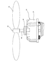
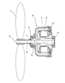
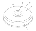
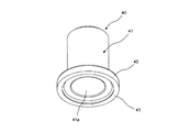
- FIG. 3 is a vertical cross-sectional view of an outdoor unit using the fan motor waterproof structure according to the first embodiment of the present disclosure. It is a side view of a fan and a fan motor of the outdoor unit. It is sectional drawing of the said fan and a fan motor. It is an expanded sectional view of the important section of the fan motor. It is the perspective view which looked at the drainage rubber from diagonally above. It is the perspective view which looked at the waterproof cap from the slanting upper part. It is the perspective view which looked at the said waterproof cap from diagonally downward.
- FIG. 9 is an enlarged cross-sectional view of a main part of a fan motor of an outdoor unit that uses a fan motor waterproof structure according to a second embodiment of the present disclosure.
- FIG. 1 is a vertical cross-sectional view of an outdoor unit 1 using a fan motor waterproof structure according to the first embodiment of the present disclosure.
- the outdoor unit 1 constitutes a part of a refrigerator or an air conditioner.
- the outdoor unit 1 of the first embodiment has a rectangular parallelepiped casing 2, a heat exchanger 3 arranged in the casing 2, and a casing 2 and an upper side of the heat exchanger 3.
- the fan motor 20 is provided.
- the fan motor 20 is arranged so that the shaft 22 projects upward from the motor body 21.
- the fan 10 is attached to the shaft 22 of the fan motor 20.
- FIG. 2 is a side view of the fan 10 and the fan motor 20 of the outdoor unit 1.
- a disk-shaped draining rubber 30 is fitted on the outer side of the protruding portion of the shaft 22 of the fan motor 20 on the motor body 21 side.
- the drainage rubber 30 is an example of a disk-shaped member, and is made of EPDM (Ethylene Propylene Diene Rubber; ethylene/propylene/diene/rubber) or the like.
- a tubular waterproof cap 40 is press-fitted on the drain rubber 30 and around the shaft 22 so as to cover the boundary between the upper surface of the drain rubber 30 and the shaft 22.
- the waterproof cap 40 is an example of a tubular member, and is made of EPDM (Ethylene Propylene Diene Rubber; ethylene/propylene/diene/rubber) or the like.
- FIG. 3 is a cross-sectional view of the fan 10 and the fan motor 20.
- an annular stator 23 is arranged in the motor body 21.
- a cylindrical rotor 24 arranged inside the motor body 21 and on the outer peripheral side of the stator 23 is fixed to the shaft 22.
- the shaft 22 is rotatably supported by bearings 25 and 26 arranged in the motor body 21.
- FIG. 4 is an enlarged cross-sectional view of the main part of the fan motor 20 (region S surrounded by the dotted line shown in FIG. 3).
- the inner peripheral side of the draining rubber 30 is fitted in an annular step portion 22 a provided on the shaft 22.
- An annular first convex portion 32 protruding upward is provided on the upper surface and the inner peripheral side of the drainage rubber 30.
- the waterproof cap 40 is provided with a cylindrical portion 41, a flange portion 42 provided at the lower end of the cylindrical portion 41 so as to extend outward, and a lower surface of the flange portion 42 and a downwardly projecting portion on the outer peripheral side. It has an annular second convex portion 43.
- a labyrinth seal is formed by the annular first convex portion 32 of the drainage rubber 30 and the annular second convex portion 43 of the waterproof cap 40. Further, a space A is formed between the drainage rubber 30 and the waterproof cap 40.
- the lower end surface of the annular second convex portion 43 of the waterproof cap 40 is in contact with the upper surface of the base 31 of the drainage rubber 30.
- FIG. 5 is a perspective view of the drainage rubber 30 as seen obliquely from above.
- the drainage rubber 30 includes a disk-shaped base 31 provided with a circular hole 30 a into which the shaft 22 is inserted, and an annular shape provided so as to project upward on the inner peripheral side of the base 31.
- the first convex portion 32 and the cylindrical portion 33 provided on the outer peripheral side of the base portion 31 so as to extend downward.
- FIG. 6 is a perspective view of the waterproof cap 40 seen from diagonally above
- FIG. 7 is a perspective view of the waterproof cap 40 seen from diagonally below.
- the cylindrical portion 41 of the waterproof cap 40 has a hole 41 a through which the shaft 22 penetrates.
- a flange portion 42 is provided at the lower end of the cylindrical portion 41 so as to extend outward.
- an annular second convex portion 43 is provided on the lower surface of the flange portion 42 and on the outer peripheral side so as to project downward.
- a taper 41b is formed on the upper end of the cylindrical portion 41 of the waterproof cap 40 so as to gradually decrease from the inner peripheral side toward the outer peripheral side.
- the waterproof cap 40 (cylindrical member) is press-fitted on the draining rubber 30 (disc-shaped member) and on the outer periphery of the shaft 22, and the waterproof cap 40 causes the upper surface of the draining rubber 30
- the waterproofness of the fan motor 20 can be improved. Therefore, it is possible to prevent corrosion of the shaft 22 and prevent water from entering the motor main body 21 along the shaft 22, thereby preventing the bearing and the like from being damaged by the invading water.
- the flange portion 42 at the lower end of the waterproof cap 40, the boundary between the upper surface of the draining rubber 30 and the shaft 22 can be reliably covered with the flange portion 42, and the waterproof property is further improved.
- annular first convex portion 32 protruding upward to the upper surface and the inner peripheral side of the drainage rubber 30, and an annular second convex portion 43 protruding downward to the lower surface and the outer peripheral side of the flange portion 42 of the waterproof cap 40.
- FIG. 8 is an enlarged cross-sectional view of a main part of a fan motor 20 of an outdoor unit using the fan motor waterproof structure according to the second embodiment of the present disclosure.
- the outdoor unit using the fan motor waterproof structure of the second embodiment has the same configuration as the outdoor unit 1 of the first embodiment except for the fan motor waterproof structure, and FIGS. 1 to 3 are cited.
- the lower end surface of the annular second convex portion 44 of the waterproof cap 40 is not in contact with the upper surface of the base portion 31 of the drainage rubber 30, and the annular second convex portion 44 of the waterproof cap 40 and the drainage rubber are included. There is a gap between the base 31 and the base 31.
- the fan motor waterproof structure in the second embodiment is the first in that the space A formed between the draining rubber 30 and the waterproof cap 40 is continuous with the open space on the radially outer side. This is different from the fan motor waterproof structure in the embodiment.
- the fan motor waterproof structure of the second embodiment has the same effect as the fan motor waterproof structure of the first embodiment.
- the space A formed between the drainage rubber 30 and the waterproof cap 40 is continuous with the open space on the outer side in the radial direction, invasion is prevented in the space A between the drainage rubber 30 and the waterproof cap 40.
- the water is discharged to the outside as the shaft 22 rotates, and the water can be prevented from staying between the drain rubber 30 and the waterproof cap 40.
- the flange portion 42 is provided at the lower end of the cylindrical portion 41 of the waterproof cap 40 that is a tubular member so as to extend outward, but the flange portion may be omitted, and for example, the tubular portion
- the boundary between the upper surface of the disk-shaped member and the shaft may be covered by increasing the radial thickness of the plate-shaped member.
- the draining rubber 30 that is a disc-shaped member is provided with the annular first convex portion 32
- the flange 42 of the waterproof cap 40 that is the tubular member is provided with the circular second convex portion.
- the labyrinth seal is formed by providing the portions 43 and 44, the annular first convex portion projecting upward is provided at a position facing the upper surface of the disc-shaped member and the outer peripheral portion of the flange portion of the tubular member.
- the labyrinth seal may be formed by providing the annular second convex portion so as to project downward on the lower surface and the inner peripheral side of the flange portion of the member.
- the labyrinth seal may be formed by providing at least one of the annular first convex portion of the disc-shaped member and the annular second convex portion of the tubular member at intervals of 2 in the radial direction.
- the labyrinth seal formed by the annular first convex portion of the disc-shaped member and the annular second convex portion of the tubular member may be omitted. Also in this case, it is possible to suppress the accumulation of dust and water at the interface between the exposed portion of the shaft and the disc-shaped member.
- the end faces of the water draining rubber 30 (disc-shaped member) and the waterproof cap 40 (cylindrical member) that face each other across the space A have a plurality of surfaces having different heights. At least one of the surfaces may be located above at least one of the plurality of surfaces of the waterproof cap 40. As a result, a maze is formed between the drainage rubber 30 and the waterproof cap 40, and it is possible to effectively prevent water from entering between the drainage rubber 30 and the waterproof cap 40.
- the materials of the draining rubber 30 which is a disk-shaped member and the waterproof cap 40 which is a tubular member are EPDM (Ethylene Propylene Diene Rubber; Ethylene Propylene Diene Rubber) etc.
- EPDM Ethylene Propylene Diene Rubber
- the material of the disk-shaped member and the cylindrical member is not limited to this, and a material having water repellency and weather resistance is preferable.
- the draining rubber 30 that is a disk-shaped member is fitted and positioned on the annular step portion 22a provided on the shaft 22, but an E-ring fitted on the shaft is used.
- the discoid member may be positioned.
Landscapes
- Engineering & Computer Science (AREA)
- Power Engineering (AREA)
- Mechanical Engineering (AREA)
- General Engineering & Computer Science (AREA)
- Motor Or Generator Frames (AREA)
- Connection Of Motors, Electrical Generators, Mechanical Devices, And The Like (AREA)
Abstract
ファンモータ防水構造は、モータ本体(21)から上方に向かってシャフト(22)が突出するように配置されたファンモータ(20)と、ファンモータ(20)のシャフト(22)の突出部分のうちのモータ本体(21)側の外側に嵌められた円板状部材(30)と、円板状部材(30)の上面とシャフト(22)との境界を覆うように、円板状部材(30)上かつシャフト(22)の外周に圧入された筒状部材(40)とを備える。
Description
本開示は、ファンモータ防水構造に関する。
従来、ファンモータ防水構造としては、回転子のシャフトと防水キャップとEリングとが組付けられたモールド電動機がある(例えば、特許第6320555号(特許文献1)参照)。
上記モールド電動機では、防水キャップによってシャフトとモータ本体との間からの水の浸入を防いでいる。
しかしながら、上記モールド電動機では、上方に向かってシャフトが突出するように配置された場合、シャフトの露出部分と防水キャップとの界面に粉塵や水が滞留することによって、シャフトが腐食するという問題がある。上記モールド電動機では、シャフトに腐食が発生すると、シャフトと防水キャップとの間の防水性が失われて、シャフトに沿ってモータ本体内に水が浸入し、シャフトの軸受などのモータ本体内の構成部品が侵入した水により損傷する恐れがある。
本開示では、ファンモータの防水性を向上できるファンモータ防水構造を提案する。
本開示のファンモータ防水構造は、
モータ本体から上方に向かってシャフトが突出するように配置されたファンモータと、
上記ファンモータの上記シャフトの突出部分のうちの上記モータ本体側の外側に嵌められた円板状部材と、
上記円板状部材の上面と上記シャフトとの境界を覆うように、上記円板状部材上かつ上記シャフトの外周に圧入された筒状部材と
を備えることを特徴とする。
モータ本体から上方に向かってシャフトが突出するように配置されたファンモータと、
上記ファンモータの上記シャフトの突出部分のうちの上記モータ本体側の外側に嵌められた円板状部材と、
上記円板状部材の上面と上記シャフトとの境界を覆うように、上記円板状部材上かつ上記シャフトの外周に圧入された筒状部材と
を備えることを特徴とする。
本開示によれば、ファンモータのシャフトの突出部分のうちのモータ本体側の外側に円板状部材が嵌められ、該円板状部材上かつシャフトの外周に筒状部材を圧入して、筒状部材により円板状部材の上面とシャフトとの境界を覆うことによって、シャフトの露出部分と円板状部材との界面に粉塵や水が滞留するのを抑制できる。これにより、ファンモータの防水性を向上できる。
また、本開示の1つの態様に係るファンモータ防水構造では、
上記円板状部材と上記筒状部材との間に空間が形成されており、該空間が径方向外側の開放空間に連なる。
上記円板状部材と上記筒状部材との間に空間が形成されており、該空間が径方向外側の開放空間に連なる。
上記本開示によれば、円板状部材と筒状部材との間に形成された空間によって、外部から円板状部材と筒状部材との間に侵入した水が毛細管現象により径方向内側に向かって浸透するのを妨げることが可能になる。さらに、円板状部材と筒状部材との間に形成された空間が径方向外側の開放空間に連なっていることにより、円板状部材と筒状部材との間の空間で侵入が妨げられた水がシャフトの回転に伴って外部に排出され、円板状部材と筒状部材との間に水が滞留しないようにできる。
また、本開示の1つの態様に係るファンモータ防水構造では、
上記空間を挟んで対向する上記円板状部材と上記筒状部材の夫々端面は、高さが異なる複数の面を有し、
上記円板状部材の上記複数の面のうちの少なくとも1つの面が、上記筒状部材の上記複数の面のうちの少なくとも1つの面よりも上方に位置する。
上記空間を挟んで対向する上記円板状部材と上記筒状部材の夫々端面は、高さが異なる複数の面を有し、
上記円板状部材の上記複数の面のうちの少なくとも1つの面が、上記筒状部材の上記複数の面のうちの少なくとも1つの面よりも上方に位置する。
上記本開示によれば、空間を挟んで対向する円板状部材と筒状部材の夫々端面が、シャフトの軸方向高さが異なる複数の面を有することによって、円板状部材と筒状部材との間に迷路が形成されて、円板状部材と筒状部材との間に水が浸入するのを効果的に抑えることができる。
また、本開示の1つの態様に係るファンモータ防水構造では、
上記筒状部材の下端にフランジ部を設けた。
上記筒状部材の下端にフランジ部を設けた。
本開示によれば、筒状部材の下端にフランジ部を設けることにより、円板状部材の上面とシャフトとの境界をフランジ部により確実に覆うことができ、防水性がさらに向上する。
また、本開示の1つの態様に係るファンモータ防水構造では、
上記筒状部材の下端にフランジ部を設け、
上記円板状部材の上面かつ内周側に上方に突出する環状の第1凸部を設けると共に、
上記筒状部材の上記フランジ部の下面かつ外周側に下方に突出する環状の第2凸部を設けており、
上記円板状部材の上記環状の第1凸部と上記筒状部材の上記環状の第2凸部によってラビリンスシールが形成されている。
上記筒状部材の下端にフランジ部を設け、
上記円板状部材の上面かつ内周側に上方に突出する環状の第1凸部を設けると共に、
上記筒状部材の上記フランジ部の下面かつ外周側に下方に突出する環状の第2凸部を設けており、
上記円板状部材の上記環状の第1凸部と上記筒状部材の上記環状の第2凸部によってラビリンスシールが形成されている。
本開示によれば、円板状部材の上面かつ内周側に上方に突出する環状の第1凸部と、筒状部材のフランジ部の下面かつ外周側に下方に突出する環状の第2凸部とにより形成されたラビリンスシールによって、円板状部材と筒状部材との間に水が浸入するのを効果的に抑えることができる。
また、本開示の1つの態様に係るファンモータ防水構造では、
上記筒状部材の上端に、内周側から外周側に向かって徐々に低くなるようにテーパが形成されている。
上記筒状部材の上端に、内周側から外周側に向かって徐々に低くなるようにテーパが形成されている。
本開示によれば、筒状部材の上端に、内周側から外周側に向かって徐々に低くなるようにテーパを形成することによって、筒状部材の上端に埃や水が滞留するのを抑制でき、筒状部材の上端側から筒状部材とシャフトとの間に水が侵入するリスクを低減できる。
以下、実施形態を説明する。なお、図面において、同一の参照番号は、同一部分または相当部分を表わすものである。また、長さ、幅、厚さ、深さ等の図面上の寸法は、図面の明瞭化と簡略化のために実際の尺度から適宜変更されており、実際の相対寸法を表してはいない。
〔第1実施形態〕
図1は本開示の第1実施形態のファンモータ防水構造を用いた室外機1の縦断面図である。室外機1は、冷凍機または空気調和機の一部を構成する。
図1は本開示の第1実施形態のファンモータ防水構造を用いた室外機1の縦断面図である。室外機1は、冷凍機または空気調和機の一部を構成する。
この第1実施形態の室外機1は、図1に示すように、直方体形状のケーシング2と、ケーシング2内に配置された熱交換器3と、ケーシング2内かつ熱交換器3の上側に配置されたファンモータ20を備えている。ファンモータ20は、モータ本体21から上方に向かってシャフト22が突出するように配置されている。ファンモータ20のシャフト22にファン10が取り付けられている。
図2は上記室外機1のファン10とファンモータ20の側面図である。図2に示すように、ファンモータ20のシャフト22の突出部分のうちのモータ本体21側の外側に円板状の水切りゴム30が嵌められている。水切りゴム30は、円板状部材の一例であり、EPDM(Ethylene Propylene Diene Rubber; エチレン・プロピレン・ジエン・ゴム)等からなる。
また、水切りゴム30の上面とシャフト22との境界を覆うように、水切りゴム30上かつシャフト22の外周に筒状の防水キャップ40が圧入されている。防水キャップ40は、筒状部材の一例であり、EPDM(Ethylene Propylene Diene Rubber; エチレン・プロピレン・ジエン・ゴム)等からなる。
また、図3は上記ファン10とファンモータ20の断面図である。図3に示すように、モータ本体21内に環状のステータ23が配置されている。モータ本体21内かつステータ23の外周側に配置された筒状のロータ24がシャフト22に固定されている。シャフト22は、モータ本体21内に配置された軸受25,26により回転可能に支持されている。
図4はファンモータ20の要部(図3に示す点線で囲まれた領域S)の拡大断面図である。図4に示すように、シャフト22に設けられた環状の段部22aに、水切りゴム30の内周側が嵌まっている。水切りゴム30の上面かつ内周側に上方に突出する環状の第1凸部32を設けている。
また、防水キャップ40は、円筒部41と、円筒部41の下端に外方に延びるように設けられたフランジ部42と、フランジ部42の下面かつ外周側に下方に突出するように設けられた環状の第2凸部43を有している。
水切りゴム30の環状の第1凸部32と防水キャップ40の環状の第2凸部43によってラビリンスシールが形成されている。また、水切りゴム30と防水キャップ40との間に空間Aが形成されている。
防水キャップ40の環状の第2凸部43の下端面は、水切りゴム30の基部31の上面に接している。
図5は水切りゴム30を斜め上方から見た斜視図である。図5に示すように、水切りゴム30は、シャフト22が挿入される円穴30aが設けられた円板状の基部31と、基部31の内周側に上方に突出するように設けられた環状の第1凸部32と、基部31の外周側に下方に向かって延びるように設けられた円筒部33とを有する。
図6は防水キャップ40を斜め上方から見た斜視図であり、図7は防水キャップ40を斜め下方から見た斜視図である。図6,図7に示すように、防水キャップ40の円筒部41は、シャフト22が貫通する穴41aを有する。また、円筒部41の下端に外方に延びるようにフランジ部42が設けられている。また、フランジ部42の下面かつ外周側に下方に突出するように環状の第2凸部43が設けられている。
防水キャップ40の円筒部41の上端に、内周側から外周側に向かって徐々に低くなるようにテーパ41bを形成している。
上記構成のファンモータ防水構造によれば、水切りゴム30(円板状部材)上かつシャフト22の外周に防水キャップ40(筒状部材)を圧入して、防水キャップ40により水切りゴム30の上面とシャフト22との境界を覆うことによって、シャフト22の露出部分と水切りゴム30との界面に粉塵や水が滞留するのを抑制できる。これにより、ファンモータ20の防水性を向上できる。したがって、シャフト22に腐食が発生してシャフト22に沿ってモータ本体21内に水が浸入するのを妨げて、侵入水による軸受などが損傷するのを抑制できる。
また、水切りゴム30と防水キャップ40との間に形成された空間Aによって、外部から水切りゴム30と防水キャップ40との間に侵入した水が毛細管現象により径方向内側に向かって浸透するのを妨げることが可能になる。
また、防水キャップ40の下端にフランジ部42を設けることにより、水切りゴム30の上面とシャフト22との境界をフランジ部42により確実に覆うことができ、防水性がさらに向上する。
また、水切りゴム30の上面かつ内周側に上方に突出する環状の第1凸部32と、防水キャップ40のフランジ部42の下面かつ外周側に下方に突出する環状の第2凸部43とにより形成されたラビリンスシールによって、水切りゴム30と防水キャップ40との間に水が浸入するのを効果的に抑えることができる。
また、防水キャップ40の円筒部41の上端に、内周側から外周側に向かって徐々に低くなるようにテーパ41bを形成することによって、防水キャップ40の上端に埃や水がテーパ41bに沿って落ちて滞留しにくくなり、防水キャップ40の上端側から防水キャップ40とシャフト22との間に水が侵入するリスクを低減できる。
〔第2実施形態〕
図8は本開示の第2実施形態のファンモータ防水構造を用いた室外機のファンモータ20の要部の拡大断面図である。この第2実施形態のファンモータ防水構造を用いた室外機は、ファンモータ防水構造を除いて第1実施形態の室外機1と同一の構成をしており、図1~図3を援用する。
図8は本開示の第2実施形態のファンモータ防水構造を用いた室外機のファンモータ20の要部の拡大断面図である。この第2実施形態のファンモータ防水構造を用いた室外機は、ファンモータ防水構造を除いて第1実施形態の室外機1と同一の構成をしており、図1~図3を援用する。
第2実施形態では、防水キャップ40の環状の第2凸部44の下端面は、水切りゴム30の基部31の上面に接しておらず、防水キャップ40の環状の第2凸部44と水切りゴム30の基部31との間に隙間を有する。
この第2実施形態におけるファンモータ防水構造は、図8に示すように、水切りゴム30と防水キャップ40との間に形成された空間Aが径方向外側の開放空間に連なっている点で第1実施形態におけるファンモータ防水構造と相違する。
上記第2実施形態のファンモータ防水構造は、第1実施形態のファンモータ防水構造と同様の効果を有する。
また、水切りゴム30と防水キャップ40との間に形成された空間Aが径方向外側の開放空間に連なっていることにより、水切りゴム30と防水キャップ40との間の空間Aで侵入が妨げられた水がシャフト22の回転に伴って外部に排出され、水切りゴム30と防水キャップ40との間に水が滞留しないようにできる。
上記第1,第2実施形態では、筒状部材である防水キャップ40の円筒部41の下端に外方に延びるようにフランジ部42を設けたが、フランジ部は無くてもよく、例えば、筒状部材の径方向の肉厚を厚くすることにより、円板状部材の上面とシャフトとの境界を覆うようにしてもよい。
また、上記第1,第2実施形態では、円板状部材である水切りゴム30に環状の第1凸部32を設け、筒状部材である防水キャップ40のフランジ部42に環状の第2凸部43,44を設けて、ラビリンスシールを形成したが、円板状部材の上面かつ筒状部材のフランジ部の外周部分に対向する位置に上方に突出する環状の第1凸部を設け、筒状部材のフランジ部の下面かつ内周側に下方に突出するように環状の第2凸部を設けて、ラビリンスシールを形成してもよい。
なお、円板状部材の環状の第1凸部および筒状部材の環状の第2凸部の少なくとも一方を、径方向に間隔をあけて2以上設けて、ラビリンスシールを形成してもよい。
また、円板状部材の環状の第1凸部と筒状部材の環状の第2凸部によるラビリンスシールが無くてもよい。この場合も、シャフトの露出部分と円板状部材との界面に粉塵や水が滞留するのを抑制することは可能である。
また、空間Aを挟んで対向する水切りゴム30(円板状部材)と防水キャップ40(筒状部材)の夫々端面が、高さが異なる複数の面を有し、水切りゴム30の複数の面のうちの少なくとも1つの面が、防水キャップ40の複数の面のうちの少なくとも1つの面よりも上方に位置するようにしてもよい。これにより、水切りゴム30と防水キャップ40との間に迷路が形成されて、水切りゴム30と防水キャップ40との間に水が浸入するのを効果的に抑えることができる。
また、上記第1,第2実施形態では、円板状部材である水切りゴム30と筒状部材である防水キャップ40の材料に、EPDM(Ethylene Propylene Diene Rubber; エチレン・プロピレン・ジエン・ゴム)等を用いたが、円板状部材と筒状部材の材料はこれに限らず、撥水性および耐候性を有する材料が好ましい。
また、上記第1,第2実施形態では、シャフト22に設けられた環状の段部22aに、円板状部材である水切りゴム30を嵌めて位置決めしたが、シャフトに嵌めたEリングを用いて円板状部材の位置決めを行ってもよい。
本開示の具体的な実施の形態について説明したが、本開示は上記第1,第2実施形態に限定されるものではなく、本開示の範囲内で種々変更して実施することができる。
1…室外機
2…ケーシング
3…熱交換器
10…ファン
20…ファンモータ
21…モータ本体
22…シャフト
23…ステータ
24…ロータ
25,26…軸受
30…水切りゴム
30a…円穴
31…円板状の基部
32…環状の第1凸部
33…円筒部
40…防水キャップ
41…円筒部
41a…穴
41b…テーパ
42…フランジ部
43,44…環状の第2凸部
2…ケーシング
3…熱交換器
10…ファン
20…ファンモータ
21…モータ本体
22…シャフト
23…ステータ
24…ロータ
25,26…軸受
30…水切りゴム
30a…円穴
31…円板状の基部
32…環状の第1凸部
33…円筒部
40…防水キャップ
41…円筒部
41a…穴
41b…テーパ
42…フランジ部
43,44…環状の第2凸部
Claims (6)
- モータ本体(21)から上方に向かってシャフト(22)が突出するように配置されたファンモータ(20)と、
上記ファンモータ(20)の上記シャフト(22)の突出部分のうちの上記モータ本体(21)側の外側に嵌められた円板状部材(30)と、
上記円板状部材(30)の上面と上記シャフト(22)との境界を覆うように、上記円板状部材(30)上かつ上記シャフト(22)の外周に圧入された筒状部材(40)と
を備えることを特徴とするファンモータ防水構造。 - 請求項1に記載のファンモータ防水構造において、
上記円板状部材(30)と上記筒状部材(40)との間に空間(A)が形成されており、該空間(A)が径方向外側の開放空間に連なることを特徴とするファンモータ防水構造。 - 請求項2に記載されたファンモータ防水構造において、
上記空間(A)を挟んで対向する上記円板状部材(30)と上記筒状部材(40)の夫々端面は、高さが異なる複数の面を有し、
上記円板状部材(30)の上記複数の面のうちの少なくとも1つの面が、上記筒状部材(40)の上記複数の面のうちの少なくとも1つの面よりも上方に位置することを特徴とするファンモータ防水構造。 - 請求項1から3までのいずれか1つに記載されたファンモータ防水構造において、
上記筒状部材(40)の下端にフランジ部(42)を設けたことを特徴とするファンモータ防水構造。 - 請求項1または2に記載のファンモータ防水構造において、
上記筒状部材(40)の下端にフランジ部(42)を設け、
上記円板状部材(30)の上面かつ内周側に上方に突出する環状の第1凸部(32)を設けると共に、
上記筒状部材(40)の上記フランジ部(42)の下面かつ外周側に下方に突出する環状の第2凸部(43,44)を設けており、
上記円板状部材(30)の上記環状の第1凸部(32)と上記筒状部材(40)の上記環状の第2凸部(43,44)によってラビリンスシールが形成されていることを特徴とするファンモータ防水構造。 - 請求項1から5までのいずれか1つに記載のファンモータ防水構造において、
上記筒状部材(40)の上端に、内周側から外周側に向かって徐々に低くなるようにテーパ(41b)が形成されていることを特徴とするファンモータ防水構造。
Priority Applications (4)
| Application Number | Priority Date | Filing Date | Title |
|---|---|---|---|
| EP19896498.3A EP3876398B1 (en) | 2018-12-10 | 2019-11-07 | Fan motor waterproof structure |
| ES19896498T ES2949567T3 (es) | 2018-12-10 | 2019-11-07 | Estructura impermeable de motor de ventilador |
| CN201980067138.4A CN112840533B (zh) | 2018-12-10 | 2019-11-07 | 风扇马达防水构造 |
| US17/311,919 US11764634B2 (en) | 2018-12-10 | 2019-11-07 | Fan motor waterproof structure |
Applications Claiming Priority (2)
| Application Number | Priority Date | Filing Date | Title |
|---|---|---|---|
| JP2018-230915 | 2018-12-10 | ||
| JP2018230915A JP6848957B2 (ja) | 2018-12-10 | 2018-12-10 | ファンモータ防水構造 |
Publications (1)
| Publication Number | Publication Date |
|---|---|
| WO2020121698A1 true WO2020121698A1 (ja) | 2020-06-18 |
Family
ID=71076322
Family Applications (1)
| Application Number | Title | Priority Date | Filing Date |
|---|---|---|---|
| PCT/JP2019/043608 Ceased WO2020121698A1 (ja) | 2018-12-10 | 2019-11-07 | ファンモータ防水構造 |
Country Status (6)
| Country | Link |
|---|---|
| US (1) | US11764634B2 (ja) |
| EP (1) | EP3876398B1 (ja) |
| JP (1) | JP6848957B2 (ja) |
| CN (1) | CN112840533B (ja) |
| ES (1) | ES2949567T3 (ja) |
| WO (1) | WO2020121698A1 (ja) |
Families Citing this family (1)
| Publication number | Priority date | Publication date | Assignee | Title |
|---|---|---|---|---|
| WO2023199475A1 (ja) * | 2022-04-14 | 2023-10-19 | ミネベアミツミ株式会社 | モータ |
Citations (3)
| Publication number | Priority date | Publication date | Assignee | Title |
|---|---|---|---|---|
| JPS54180210U (ja) * | 1978-06-09 | 1979-12-20 | ||
| JP2014107909A (ja) * | 2012-11-26 | 2014-06-09 | Sumitomo Heavy Ind Ltd | モータの防水構造 |
| JP6320555B2 (ja) | 2014-10-24 | 2018-05-09 | 三菱電機株式会社 | 電動機の固定子、電動機および空気調和機 |
Family Cites Families (4)
| Publication number | Priority date | Publication date | Assignee | Title |
|---|---|---|---|---|
| JPH038060Y2 (ja) | 1985-07-19 | 1991-02-27 | ||
| CN2229566Y (zh) * | 1995-04-13 | 1996-06-19 | 长春市北方变压器组件研究所 | 变压器风扇轴伸迷宫式密封防护装置 |
| JP5000851B2 (ja) * | 2005-02-16 | 2012-08-15 | プライムアースEvエナジー株式会社 | ファン構造及び電池パック |
| CN103742430B (zh) * | 2013-12-19 | 2015-05-27 | 浙江双双制冷设备有限公司 | 一种离心风机用电机组件 |
-
2018
- 2018-12-10 JP JP2018230915A patent/JP6848957B2/ja active Active
-
2019
- 2019-11-07 ES ES19896498T patent/ES2949567T3/es active Active
- 2019-11-07 EP EP19896498.3A patent/EP3876398B1/en active Active
- 2019-11-07 WO PCT/JP2019/043608 patent/WO2020121698A1/ja not_active Ceased
- 2019-11-07 US US17/311,919 patent/US11764634B2/en active Active
- 2019-11-07 CN CN201980067138.4A patent/CN112840533B/zh active Active
Patent Citations (3)
| Publication number | Priority date | Publication date | Assignee | Title |
|---|---|---|---|---|
| JPS54180210U (ja) * | 1978-06-09 | 1979-12-20 | ||
| JP2014107909A (ja) * | 2012-11-26 | 2014-06-09 | Sumitomo Heavy Ind Ltd | モータの防水構造 |
| JP6320555B2 (ja) | 2014-10-24 | 2018-05-09 | 三菱電機株式会社 | 電動機の固定子、電動機および空気調和機 |
Also Published As
| Publication number | Publication date |
|---|---|
| EP3876398B1 (en) | 2023-06-21 |
| ES2949567T3 (es) | 2023-09-29 |
| US20220029499A1 (en) | 2022-01-27 |
| JP2020096406A (ja) | 2020-06-18 |
| EP3876398A1 (en) | 2021-09-08 |
| EP3876398A4 (en) | 2021-12-29 |
| JP6848957B2 (ja) | 2021-03-24 |
| US11764634B2 (en) | 2023-09-19 |
| CN112840533B (zh) | 2024-06-18 |
| CN112840533A (zh) | 2021-05-25 |
Similar Documents
| Publication | Publication Date | Title |
|---|---|---|
| KR101493635B1 (ko) | 팬 모터 | |
| JP5636788B2 (ja) | 送風ファン | |
| KR20130098302A (ko) | 구름 베어링용 밀봉 어셈블리 | |
| US10920787B2 (en) | Blower | |
| JP6354309B2 (ja) | ブロワ装置 | |
| JP2016165198A (ja) | 回転機の防水構造及び回転機 | |
| WO2020121698A1 (ja) | ファンモータ防水構造 | |
| JP2012047248A (ja) | 転がり軸受 | |
| KR20140023993A (ko) | 전기 기기용 스러스트 와셔 | |
| KR20150074293A (ko) | 팬 모터 | |
| JP2008298285A (ja) | 軸受構造、軸受構造を有するモーター及び軸受構造を有するファン | |
| US20170295998A1 (en) | Cutter device of jar | |
| US2743385A (en) | Vertical dynamoelectric machine | |
| US8753077B2 (en) | Slinger shield structure | |
| JP2017026103A (ja) | 密封装置 | |
| JP2015142437A (ja) | 電動機 | |
| JP2009024649A (ja) | 防滴構造を備えた遠心ファン | |
| KR20120002880A (ko) | 모터 | |
| WO2020036941A1 (en) | Bearing protector | |
| KR20170036835A (ko) | 구름베어링용 씰 | |
| JP6314076B2 (ja) | 回転電機及び防水構造体 | |
| CN116964343A (zh) | 轴承保护器 | |
| GB2539879A (en) | A seal for a rotating shaft | |
| JPS5941135A (ja) | 軸受箱の防水装置 | |
| KR20180107658A (ko) | 플링거 틸팅 방지용 분리홈이 형성된 베어링용 씰 |
Legal Events
| Date | Code | Title | Description |
|---|---|---|---|
| 121 | Ep: the epo has been informed by wipo that ep was designated in this application |
Ref document number: 19896498 Country of ref document: EP Kind code of ref document: A1 |
|
| ENP | Entry into the national phase |
Ref document number: 2019896498 Country of ref document: EP Effective date: 20210531 |
|
| NENP | Non-entry into the national phase |
Ref country code: DE |